US7274641B2 - Replay or recording appliance for optical recording media having an inclination control system - Google Patents
Replay or recording appliance for optical recording media having an inclination control system Download PDFInfo
- Publication number
- US7274641B2 US7274641B2 US10/827,954 US82795404A US7274641B2 US 7274641 B2 US7274641 B2 US 7274641B2 US 82795404 A US82795404 A US 82795404A US 7274641 B2 US7274641 B2 US 7274641B2
- Authority
- US
- United States
- Prior art keywords
- signal
- recording medium
- optical recording
- inclination
- radio
- Prior art date
- Legal status (The legal status is an assumption and is not a legal conclusion. Google has not performed a legal analysis and makes no representation as to the accuracy of the status listed.)
- Expired - Fee Related, expires
Links
- 230000003287 optical effect Effects 0.000 title claims abstract description 90
- 238000000034 method Methods 0.000 claims abstract description 21
- 238000011144 upstream manufacturing Methods 0.000 claims abstract description 4
- 238000001914 filtration Methods 0.000 claims description 3
- 230000008859 change Effects 0.000 description 8
- 230000008569 process Effects 0.000 description 5
- 238000004519 manufacturing process Methods 0.000 description 4
- 238000010586 diagram Methods 0.000 description 3
- 230000000712 assembly Effects 0.000 description 2
- 238000000429 assembly Methods 0.000 description 2
- 230000008878 coupling Effects 0.000 description 2
- 238000010168 coupling process Methods 0.000 description 2
- 238000005859 coupling reaction Methods 0.000 description 2
- 230000007547 defect Effects 0.000 description 2
- 230000001419 dependent effect Effects 0.000 description 2
- 238000001514 detection method Methods 0.000 description 2
- 230000000694 effects Effects 0.000 description 2
- 230000006870 function Effects 0.000 description 2
- 230000014509 gene expression Effects 0.000 description 2
- 230000010354 integration Effects 0.000 description 2
- 230000008901 benefit Effects 0.000 description 1
- 230000003247 decreasing effect Effects 0.000 description 1
- 230000001066 destructive effect Effects 0.000 description 1
- 230000007935 neutral effect Effects 0.000 description 1
- 230000010363 phase shift Effects 0.000 description 1
- 230000005855 radiation Effects 0.000 description 1
- 230000009467 reduction Effects 0.000 description 1
- 230000000717 retained effect Effects 0.000 description 1
- 230000011664 signaling Effects 0.000 description 1
Images




Classifications
-
- G—PHYSICS
- G11—INFORMATION STORAGE
- G11B—INFORMATION STORAGE BASED ON RELATIVE MOVEMENT BETWEEN RECORD CARRIER AND TRANSDUCER
- G11B7/00—Recording or reproducing by optical means, e.g. recording using a thermal beam of optical radiation by modifying optical properties or the physical structure, reproducing using an optical beam at lower power by sensing optical properties; Record carriers therefor
- G11B7/08—Disposition or mounting of heads or light sources relatively to record carriers
- G11B7/09—Disposition or mounting of heads or light sources relatively to record carriers with provision for moving the light beam or focus plane for the purpose of maintaining alignment of the light beam relative to the record carrier during transducing operation, e.g. to compensate for surface irregularities of the latter or for track following
- G11B7/095—Disposition or mounting of heads or light sources relatively to record carriers with provision for moving the light beam or focus plane for the purpose of maintaining alignment of the light beam relative to the record carrier during transducing operation, e.g. to compensate for surface irregularities of the latter or for track following specially adapted for discs, e.g. for compensation of eccentricity or wobble
- G11B7/0956—Disposition or mounting of heads or light sources relatively to record carriers with provision for moving the light beam or focus plane for the purpose of maintaining alignment of the light beam relative to the record carrier during transducing operation, e.g. to compensate for surface irregularities of the latter or for track following specially adapted for discs, e.g. for compensation of eccentricity or wobble to compensate for tilt, skew, warp or inclination of the disc, i.e. maintain the optical axis at right angles to the disc
-
- B—PERFORMING OPERATIONS; TRANSPORTING
- B60—VEHICLES IN GENERAL
- B60N—SEATS SPECIALLY ADAPTED FOR VEHICLES; VEHICLE PASSENGER ACCOMMODATION NOT OTHERWISE PROVIDED FOR
- B60N2/00—Seats specially adapted for vehicles; Arrangement or mounting of seats in vehicles
- B60N2/24—Seats specially adapted for vehicles; Arrangement or mounting of seats in vehicles for particular purposes or particular vehicles
- B60N2/30—Non-dismountable or dismountable seats storable in a non-use position, e.g. foldable spare seats
- B60N2/3088—Non-dismountable or dismountable seats storable in a non-use position, e.g. foldable spare seats characterised by the mechanical link
- B60N2/309—Non-dismountable or dismountable seats storable in a non-use position, e.g. foldable spare seats characterised by the mechanical link rods
-
- B—PERFORMING OPERATIONS; TRANSPORTING
- B60—VEHICLES IN GENERAL
- B60N—SEATS SPECIALLY ADAPTED FOR VEHICLES; VEHICLE PASSENGER ACCOMMODATION NOT OTHERWISE PROVIDED FOR
- B60N2/00—Seats specially adapted for vehicles; Arrangement or mounting of seats in vehicles
- B60N2/24—Seats specially adapted for vehicles; Arrangement or mounting of seats in vehicles for particular purposes or particular vehicles
- B60N2/30—Non-dismountable or dismountable seats storable in a non-use position, e.g. foldable spare seats
- B60N2/3002—Non-dismountable or dismountable seats storable in a non-use position, e.g. foldable spare seats back-rest movements
- B60N2/3029—Non-dismountable or dismountable seats storable in a non-use position, e.g. foldable spare seats back-rest movements by composed movement
- B60N2/3031—Non-dismountable or dismountable seats storable in a non-use position, e.g. foldable spare seats back-rest movements by composed movement in a longitudinal-vertical plane
-
- G—PHYSICS
- G11—INFORMATION STORAGE
- G11B—INFORMATION STORAGE BASED ON RELATIVE MOVEMENT BETWEEN RECORD CARRIER AND TRANSDUCER
- G11B7/00—Recording or reproducing by optical means, e.g. recording using a thermal beam of optical radiation by modifying optical properties or the physical structure, reproducing using an optical beam at lower power by sensing optical properties; Record carriers therefor
- G11B7/004—Recording, reproducing or erasing methods; Read, write or erase circuits therefor
- G11B7/005—Reproducing
- G11B7/0053—Reproducing non-user data, e.g. wobbled address, prepits, BCA
-
- G—PHYSICS
- G11—INFORMATION STORAGE
- G11B—INFORMATION STORAGE BASED ON RELATIVE MOVEMENT BETWEEN RECORD CARRIER AND TRANSDUCER
- G11B7/00—Recording or reproducing by optical means, e.g. recording using a thermal beam of optical radiation by modifying optical properties or the physical structure, reproducing using an optical beam at lower power by sensing optical properties; Record carriers therefor
- G11B7/08—Disposition or mounting of heads or light sources relatively to record carriers
- G11B7/09—Disposition or mounting of heads or light sources relatively to record carriers with provision for moving the light beam or focus plane for the purpose of maintaining alignment of the light beam relative to the record carrier during transducing operation, e.g. to compensate for surface irregularities of the latter or for track following
- G11B7/0925—Electromechanical actuators for lens positioning
Definitions
- the invention relates to a method and an arrangement for a replay or recording appliance for optical recording media having an inclination control system which aligns the scanning beam at right angles, at least in one direction, to the optical recording medium, such as a CD, DVD or Blue Disc.
- Optical recording media such as CDs, DVDs or Blue Disc
- Optical recording media are frequently bent radially outwards, upwards or downwards and can neither be recorded on nor replayed by means of a conventional scanning device which guides the scanning beam exclusively on the track and in the focus direction of the recording medium.
- This is particularly applicable to recording media which are composed of a number of layers, such as DVDs.
- Recording media which are curved from the inside to the outside are also referred to as umbrella disks, owing to the curvature.
- the surface of a disk such as this has an inclination, which is referred to as radial tilt, with respect to a plane, so that it is necessary to tilt the scanning device or the actuator in order to align the scanning beam at right angles to the recording medium, since optimum recording or replay of information is ensured only when the scanning beam is aligned at right angles to the recording medium.
- Recording medium curvature which is known in the German language by the expression Plattenschlag [disk impact] and is repeated with each revolution of the recording medium generally leads to both a radial tilt and tangential tilt.
- An appliance for aligning the scanning beam at right angles to the recording medium by tilting the scanning device is already known from U.S. Pat. No. 5,034,939.
- the error rate in a data signal which is read from the recording medium is used for alignment at right angles and/or in order to vary the inclination of the scanning beam.
- a minimum error rate in this case corresponds to optimum tilt correction.
- a tilt servo circuit is known from U.S. Pat. No. 5,001,690, by means of which the inclination angle of the scanning beam is varied in order to achieve a maximum level of the reproduced information signal or HF signal which is detected from the recording medium.
- the error rate and the level of the HF signal are dependent not only on the tilt but also on numerous other factors, such as scratches, so-called black dots, the depth of the pits, the reflection level of the disk and any focus offset.
- the object of the invention is to provide a method and an arrangement for a replay or recording appliance for optical recording media having an inclination control system which very largely overcome the disadvantages which have been mentioned, and which can be implemented with little complexity, and nonetheless without any additional inclination sensors.
- One aspect of the invention is to align the scanning beam in a replay or recording appliance for optical recording media at right angles to the recording medium without any additional inclination sensors and very largely uninfluenced by other factors which, in addition to the inclination of the scanning beam, influence the detected radio-frequency signal.
- the scanning beam which is intended for recording or replaying information, is slaved to the discrepancies between the recording medium and a plane by means of an inclination control system, or the scanning device which produces the scanning beam is aligned at right angles to the recording medium in the event of any tilt or inclination.
- the alignment of the scanning device at right angles to the recording medium by means of an inclination control system has the advantage, in addition to improved recording or replay, that the adjustment process for the scanning device during the production of the recording or replay appliance can be carried out with less accuracy.
- the aim of the invention is likewise to detect as high a radio-frequency signal as possible from the recording medium by alignment of the scanning beam at right angles to the recording medium, other factors which, in addition to the inclination of the scanning beam, influence the amplitude and/or the level of the radio-frequency signal should, however, very largely be excluded from the control of the inclination of the scanning beam.
- a further aim is to avoid additional inclination sensors and a control process based on the so-called trial and error principle.
- An inclination control system is therefore provided which is based on a lower envelope curve signal or the mirror signal of a radio-frequency signal which is detected from the recording medium and which corresponds to the dark value of a radio-frequency signal which is detected from the optical recording medium.
- the lower envelope curve signal or the mirror signal is multiplied by a modulation signal and is integrated in order to form a control error which corresponds to the inclination of the scanning beam with respect to the optical recording medium.
- the modulation signal which is likewise added to the signal for controlling the means for adjustment of the inclination of the scanning beam which is directed at the recording medium, is, according to one exemplary embodiment, a square-wave signal with a polarity that changes after a zero signal phase or pause.
- the amplitude of the modulation signal was, in one embodiment, chosen such that it results in the inclination of the scanning beam being changed by approximately 1/30 degree or 2 minutes of arc.
- a symmetrical square-wave signal at a frequency of 4 Hz with the stated amplitude and having a 50% zero component is used as the modulation signal.
- other signal forms such as a sinusoidal, triangular waveform or sawtooth waveform signal may also be used as the modulation signal.
- a modulation signal with a period duration which corresponds at least to one revolution of the recording medium is advantageous, although it is also possible to use other frequencies which take account of the requirements for the speed of the inclination control system.
- the modulation signal which is used for inclination control is chosen such that it is virtually undetectable in the radio-frequency signal which is detected from the recording medium. Since the inclination angle varies relatively slowly during the scanning of the recording medium, a low modulation signal frequency is sufficient for inclination control.
- the lower envelope curve signal is multiplied by the modulation signal and is then integrated in order to directly determine a control error which represents the error in the alignment of the scanning beam at right angles to the recording medium, thus resulting in dynamic and immediately effective inclination control.
- a so-called mirror signal detector is already provided in appliances such as these for detection of track changes, and this produces the lower envelope curve signal that is referred to as the mirror signal.
- the mirror signal which is normally used only with an open track control loop when the scanning beam leaves the recording track, is in this case used for inclination control in a closed track control loop.
- a multiplier, a modulator and an inclination controller are provided in order to produce the inclination angle control loop, so that the circuit arrangement which may, for example, be in the form of a digital circuit arrangement involves little complexity.
- the signal from the lower envelope curve which is produced by an envelope curve detector or a wobble signal detector is supplied to a multiplier, which is connected to the modulator in order to produce the modulation signal.
- Multiplication of the envelope curve signal by the modulation signal results in the correlation of the envelope curve signal with the modulation signal, so that integration of the signal over at least one period duration results in a control error which corresponds to the inclination and is supplied to an inclination controller, which is connected to the multiplier and whose output is connected to the modulator and to a means for adjustment of the inclination of the scanning beam.
- the output signal from the inclination controller is used in the actuator in order to drive a coil for the inclination of the scanning beam, which coil is comparable with the coils for tracking or focusing and has a comparable transfer function, thus allowing fast inclination angle changes in the range above 100 Hz.
- the A/D- and D/A-converters which are provided in recording or replay appliances for optical recording media with digital servo control loops, in order to control the scanning device and for digitization by means of the scanning device of signals which are detected from the recording medium may likewise be used for the inclination control loop, since the signal frequency is low.
- Known 3D actuators may be used for alignment of the scanning beam at right angles to the recording medium, with 3D actuators such as these aligning the inclination angle of the scanning beam with respect to the recording medium by means of coils or a motor.
- the method and the arrangement can be used both in recording appliances and in replay appliances since recording media such as these have a wobble track for recording of information, which likewise produces a radio-frequency signal which is detected by a wobble signal detector.
- the proposed inclination control loop does not require any additional processor power, so that the central processor unit in the appliance is not loaded by decisions on the direction of the inclination angle change.
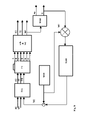
- FIG. 1 shows a block diagram of a circuit arrangement for inclination control in a replay appliance for optical recording media
- FIG. 2 shows an outline sketch relating to the alignment of the scanning beam for a recording medium which is curved upwards
- FIG. 3 shows an outline sketch relating to the alignment of the scanning beam for a recording medium which is curved downwards
- FIG. 4 shows an outline sketch relating to the configuration of a known optical scanning device
- FIG. 5 shows an outline sketch relating to the alignment of the scanning beam with a known optical scanning device
- FIG. 6 shows an outline sketch relating to the tangential inclination of the scanning beam with respect to the recording medium
- FIG. 7 shows an outline sketch relating to the radial inclination of the scanning beam with respect to the recording medium
- FIG. 8 shows a block diagram of a circuit arrangement for inclination control in a recording appliance for optical recording media
- FIG. 9 shows an outline sketch in order to illustrate scanning beam inclination
- FIG. 10 shows an outline sketch relating to the scanning change with the inclination of the scanning beam
- FIG. 11 shows a diagram of the relationship between the lower envelope curve and the inclination of the scanning beam
- FIG. 12 shows an outline sketch in order to illustrate the radio-frequency signal for a large inclination
- FIG. 13 shows a modulation signal
- FIG. 14 shows an outline sketch in order to illustrate the radio-frequency signal with reduced inclination
- FIG. 15 shows a modulation signal
- FIG. 16 shows an outline sketch in order to illustrate the radio-frequency signal when the scanning beam is aligned at right angles
- FIG. 17 shows a modulation signal
- Recording or replay appliances for optical recording media have a scanning device PU which is used to scan an optical recording medium OD that is not illustrated in FIG. 1 .
- the scanning device PU is driven in a known manner by a track error signal TE and a focus error signal FE for tracking and focusing the scanning beam on the optical recording medium OD.
- the light which is reflected from the optical recording medium OD is detected by means of photodetectors A to F and is supplied in digital servo control loops via at least one analog/digital converter A/D and/or signal production means SG to the controllers for controlling the tracking and for focusing.
- the scanning device PU produces a radio-frequency signal HF which is detected from the optical recording medium OD and corresponds to the light intensity.
- the reproduced information signal is formed by high-pass filtering of the HF signal.
- the radio-frequency signal HF is also supplied in a known manner to an envelope curve detector ENV, which produces the upper envelope curve signal up, which corresponds to the intensity of so-called lands, and the lower envelope curve signal lo of the radio-frequency signal HF.
- the lower envelope curve signal corresponds to the intensity of the pits.
- These envelope curve signals up, lo are generally produced in recording or replay appliances for optical recording media OD in order, for example, to make it possible to evaluate track changes or disturbances on the optical recording medium OD with high reliability.
- the lower envelope curve signal lo is also referred to as the mirror signal and, in the case of an open track control loop, is generally used for signaling track changes.
- FIGS. 12 , 14 , 16 show radio-frequency signals HF with a different level or different amplitude, which is influenced by the inclination of the scanning beam with respect to the optical recording medium OD.
- FIGS. 6 and 7 show radio-frequency signals HF with a different level or different amplitude, which is influenced by the inclination of the scanning beam with respect to the optical recording medium OD.
- FIG. 6 shows the tangential inclination of a scanning beam with respect to the recording track on the optical recording medium OD, where the inclination angle ⁇ of the scanning beam with respect to a perpendicular to the optical recording medium OD is the tangential inclination angle ⁇ . While a tangential inclination angle ⁇ leads to the pits on the optical recording medium OD possibly being read with a different length, a radial inclination angle ⁇ leads to a reduced level or reduced amplitude of the radio-frequency signal HF which is scanned from the optical recording medium OD.
- the level or the amplitude of the radio-frequency signal HF is reduced because the inclination of the scanning beam with respect to a perpendicular to the optical recording medium OD leads to a broader scanning light spot.
- the beam is assumed to be circular, then an elliptical area is reflected if there is any inclination.
- the elliptical area corresponds completely to the mirror area, and the intensity of the scanning beam is relatively independent of the inclination.
- the intensity is changed since an optimum pit intensity or an optimum dark value by cancellation is achieved only when the incident radiation is at right angles.
- the scanning beam is focused on the optical recording medium by means of a focus control loop so that, as is illustrated in FIG.
- a circular light spot with a predetermined diameter is formed on the information track T on the optical recording medium OD when aligned at right angles to the optical recording medium OD.
- the light which is reflected from the optical recording medium OD is detected by means of the scanning device PU, which has a known configuration photodetector (which comprises four quadrants A, B, C, D) for the main beam and two secondary beam detectors E, F.
- the signals from the secondary beam detectors E, F are generally used to form the track error signal TE for CD recording media OD, while the difference signal between the sum of opposite quadrants of the main beam detector is used to form the focus error signal FE, and the sum signal of the quadrants A, B, C, D is used to form the information signal or the radio-frequency signal HF.
- the focus control loop for a scanning device PU such as this controls the objective lens of the scanning device PU to a position such that a circular light spot is always formed on the photodetector.
- optical recording media OD with information storage elements which are formed by depressions or projections, the so-called pits or the so-called trenches in the case of writeable optical recording media OD is, however, based on the principle of destructive interference, so that a predetermined relationship must be maintained between a projection and a depression which are illuminated at the same time in order to cancel out the scanning beam which is reflected from the recording medium OD.
- the scanning light spot has an extent a with respect to the information track width T of the optical recording medium OD.
- the proportion of the light which is reflected from the mirror surface that is located between the information tracks is greater than the proportion which is reflected from the depression or from the information track. Since the depression which forms the information track on the recording medium OD is chosen so as to produce a phase shift which leads to the cancellation of the scanning beam, a broader scanning light spot from the recording medium OD results in a lower dark value being detected.
- the maximum value of the light which is reflected from the recording medium OD between the tracks of the recording medium OD or away from the depressions in contrast remains constant.
- the change between depressions and projections on the information carrier layer of the recording medium OD is detected by the scanning device PU as the radio-frequency signal HF.
- the reduction in the cancellation of the scanning beam which is reflected from the recording medium then leads to the radio-frequency signal HF having a lower level or a lower amplitude since the difference between the maximum value and the minimum value of the radio-frequency signal HF is referred to as the level or amplitude of the radio-frequency signal HF.
- the maximum values of the radio-frequency signal HF form the upper envelope curve signal up, and the minimum values of the radio-frequency signal HF form the lower envelope curve signal lo of the radio-frequency signal HF.
- the ratio of the lower envelope curve Low Env to a maximum value AD-Max which is detected from the quadrants A . . . D of the photodetector of the scanning device PU is at a minimum when the scanning beam is aligned at right angles to the recording medium OD, as is illustrated in FIG. 11 .
- the ratio of the error Tilt from an alignment of the scanning beam at right angles to the recording medium OD with respect to the alignment without any error Tilto is used as the abscissa for the graph in FIG. 11 .
- the scanning beam and the optical axis OA of the scanning device PU must always be aligned at right angles to the optical recording medium OD even when the optical recording media OD are curved, as is illustrated in FIGS. 2 and 3 .
- the curvature of the recording media OD generally increases from an inner radius IDR via a middle radius MDR to an outer radius ODR, and the optical recording medium OD may be curved upwards, as is illustrated in FIG. 2 , or downwards, as is illustrated in FIG. 3 .
- optical recording medium OD it is also possible for the optical recording medium OD to be curved upwards as far as a specific radius, and then to be curved downwards, or vice versa.
- the smallest curvature generally occurs at the inner radius IDR of the optical recording medium OD.
- the tilting of the optical axis OA with respect to the alignment at right angles to the optical recording medium OD was originally neither intended nor required for low storage density optical recording media OD such as CDs, so that a scanning device PU as illustrated by way of example in FIG. 4 was adequate.
- An optical scanning device PU as is illustrated in FIG. 4 comprises an objective lens OL which is mounted on a lens holder LH which is elastically supported on a wire holder VW via four wires SPW.
- the wire holder WH is mounted on a base plate AP, which is also fitted with magnets M.
- a focus coil FC and tracking coils TC are provided on the lens holder LH and are driven via the wires SPW in order to deflect the objective lens in the track and/or focus direction.
- the laser and the photodetectors for production and detection of the scanning beam, respectively, are arranged, in a manner which is not illustrated, underneath the lens holder LH.
- the scanning device PU is generally arranged on a coarse drive in order to make it possible to scan the optical recording medium OD over the entire area of the information carrier layer. As is illustrated in FIG. 5 , scanning devices PU such as these do not take account of any curvature of the optical recording medium OD.
- the optical axis OA of the scanning device PU was aligned at right angles to a planar recording medium OD during the production process, and this alignment of the optical axis OA is also retained during the scanning of curved recording media OD by means of the parallel guidance that is formed by the wires SPW.
- scanning devices PU are already known in which the optical axis OA is matched to the curvature of the optical recording medium by tilting the scanning device PU, as is illustrated in FIG. 4 , by means of a motor or by tilting the objective lens OL.
- Additional coils are then provided in order to tilt the objective lens OL, by means of which coils the lens holder LH and the objective lens OL are additionally inclined for deflection in the focus and track direction.
- a control loop is provided by means of which the optical axis OA is appropriately slaved to the curvature of the optical recording medium OD in order to always ensure that the scanning beam is aligned at right angles to the optical recording medium OD despite the curvature of the recording medium OD or if the scanning device PU is positioned obliquely when it is in the neutral position.
- a control loop which makes use of an envelope curve which represents the dark value of a radio-frequency signal HF that is scanned from the optical recording medium OD.
- this envelope curve is the lower envelope curve signal lo of the radio-frequency signal HF which is detected from the information track on the optical recording medium OD.
- the lower envelope curve signal lo as is illustrated in FIG. 12 , is relatively far away from a zero line N if the scanning beam has an inclination which needs to be corrected with respect to the recording medium OD, and is relatively close to the upper envelope curve up of the radio-frequency signal HF.
- the level or the amplitude of the detected radio-frequency signal HF which is required in order to replay the information that is stored on the recording medium OD is less than that when the scanning beam is aligned at right angles, as is shown by a comparison of FIGS. 12 and 16 .
- the inclination of the scanning beam is corrected by use of a modulation signal MO, which is illustrated on a larger scale in FIGS. 13 , 15 and 17 in order to illustrate the principle.
- a modulation signal MO is used which is a symmetrical square-wave signal with a 50% zero component and at a frequency of 4 Hz.
- a symmetrical square-wave signal with a 50% zero component in this case describes a signal in which square-wave pulses of different polarity alternate separated by a zero signal, which is in each case of equal length, during one period.
- the modulation signal MO may also be used as the modulation signal MO.
- the lower envelope curve signal lo is on the one hand multiplied by the modulation signal MO and is on the other hand added to the control signal in order to vary the inclination of the scanning beam with respect to the recording medium OD.
- the lower envelope curve lo (which is likewise illustrated enlarged in FIG. 14 ) of the radio-frequency signal HF to a lower dark value being achieved for a deflection which goes beyond the alignment at right angles.
- a symmetrical modulation signal MO is used, the effects in the lower envelope curve lo of the radio-frequency signal HF remain asymmetric or unequal, however, for as long as the scanning beam is inclined or is not at right angles.
- the lower envelope curve signal lo has an asymmetry which is used to control the inclination of the scanning beam.
- the lower envelope curve signal lo is multiplied by the modulation signal MO upstream of the inclination controller TIER to which the control error is supplied.
- FIG. 16 shows modulation of the lower envelope curve signal although, in practice, this is no longer perceptible.
- Both the positive and the negative amplitude of the modulation signal MO lead to a lower dark value which is the same for both directions of the modulation signal MO when the scanning beam is aligned at right angles to the recording medium OD, so that the control error is zero.
- a scanning beam inclination other than 90 degrees asymmetrically modulates the modulation signal MO which is added via the adder + to the control signal in order to adjust the inclination of the scanning beam, so that a control error can be detected even after integration over one period of the modulation signal MO.
- the envelope curve signals lo, up can be produced both by capacitive coupling and by DC coupling from the radio-frequency signal HF, with the DC connection of the envelope curve detector ENV to the photodetectors having been found to be advantageous.
- the inclination control loop may, as is illustrated in FIG. 1 , be in the form of a digital control loop, using assemblies which are already available in the recording or replay appliance.
- the radio-frequency sum signal from the photodetectors A, B, C, D is used, after high-pass filtering, as the information signal, which is also referred to as the so-called reproduced signal, with the abbreviation RF.
- the reproduced signal loses the characteristics which are used by the radio-frequency signal HF to form the envelope curve signals lo, up.
- Optical recording media OD on which no information signals are yet stored have information written to them in recording appliances.
- recording media OD such as these already have a so-called trench in the form of a wobble track even before they are recorded, and this is used for the recording of information.
- the wobble track on the optical recording medium OD which is also used for determining the location on the recording medium OD, is likewise detected by the scanning device PU and, analogously to optical recording media OD which already have recorded information, supplies a radio-frequency signal HF which is referred to as the wobble signal WOB.
- the lower envelope curve of the wobble signal WOB is then used for inclination control in recording appliances for optical recording media OD.
- the corresponding circuit arrangement for implementation of the method is illustrated in FIG. 8 .
- FIG. 8 differs from FIG. 1 only in that the envelope curve detector ENV is replaced by a wobble signal detector WOB.
- the lower envelope curve signal lo of the wobble signal WOB likewise represents the dark value of the radio-frequency signal HF or of the wobble signal WOB, so that the method and the arrangement can be used in the same way for recording and replay appliances.
- the lower envelope curve signal lo of a radio-frequency signal HF which is detected from the optical recording medium OD is multiplied by a modulation signal MO and is integrated or low-pass filtered in order to form a control error, which corresponds to a discrepancy between the scanning beam, which is directed at the optical recording medium OD, and the perpendicular.
- the inclination control loop is formed from a multiplier MU, a modulator MOD and an inclination controller TIER, so that the circuit arrangement involves little complexity.
- the modulator MOD is connected to the multiplier MU and to an adder+, which is connected to the output of the inclination controller TIER, and the multiplier MU, to which the lower envelope curve signal lo is also supplied, is connected to the input of the inclination controller TIER, whose output, as is illustrated in FIG. 1 , is connected via a digital/analog converter D/A to the scanning device PU, which has a means for adjusting the inclination of the scanning beam.
Landscapes
- Engineering & Computer Science (AREA)
- Aviation & Aerospace Engineering (AREA)
- Transportation (AREA)
- Mechanical Engineering (AREA)
- Optical Recording Or Reproduction (AREA)
Applications Claiming Priority (2)
| Application Number | Priority Date | Filing Date | Title |
|---|---|---|---|
| DE10319757A DE10319757A1 (de) | 2003-04-30 | 2003-04-30 | Wiedergabe- oder Aufzeichnungsgerät für optische Aufzeichnungsträger mit einer Neigungsregelung |
| DE10319757.5 | 2003-04-30 |
Publications (2)
| Publication Number | Publication Date |
|---|---|
| US20040218495A1 US20040218495A1 (en) | 2004-11-04 |
| US7274641B2 true US7274641B2 (en) | 2007-09-25 |
Family
ID=32981203
Family Applications (1)
| Application Number | Title | Priority Date | Filing Date |
|---|---|---|---|
| US10/827,954 Expired - Fee Related US7274641B2 (en) | 2003-04-30 | 2004-04-20 | Replay or recording appliance for optical recording media having an inclination control system |
Country Status (8)
| Country | Link |
|---|---|
| US (1) | US7274641B2 (fr) |
| EP (1) | EP1473716A3 (fr) |
| JP (1) | JP4204510B2 (fr) |
| KR (1) | KR20040094315A (fr) |
| CN (1) | CN100407304C (fr) |
| DE (1) | DE10319757A1 (fr) |
| MY (1) | MY137931A (fr) |
| TW (1) | TWI310941B (fr) |
Families Citing this family (3)
| Publication number | Priority date | Publication date | Assignee | Title |
|---|---|---|---|---|
| CN101331544A (zh) * | 2005-12-13 | 2008-12-24 | 皇家飞利浦电子股份有限公司 | 用于倾斜补偿的透镜定位方法以及用于在光盘上读取和记录数据的方法和设备 |
| US12387755B2 (en) * | 2023-12-18 | 2025-08-12 | Western Digital Technologies, Inc. | Hard disk drive disk media curvature mitigation |
| JP2025110590A (ja) * | 2024-01-16 | 2025-07-29 | 株式会社東芝 | 磁気ディスク装置の製造方法および磁気ディスク装置 |
Citations (5)
| Publication number | Priority date | Publication date | Assignee | Title |
|---|---|---|---|---|
| US5627808A (en) | 1996-02-21 | 1997-05-06 | Eastman Kodak Company | Cross-track tilt error compensation method for optical disc drives |
| DE19824056A1 (de) | 1998-05-29 | 1999-12-02 | Thomson Brandt Gmbh | Gerät zur Wiedergabe oder Aufzeichnung von Daten oder Informationen |
| US6526007B1 (en) | 1999-06-10 | 2003-02-25 | Sony Corporation | Recording medium driving device for rotationally driving a disk-shaped recording medium having tilt detection means and tilt detection method |
| US6788627B2 (en) * | 2000-06-27 | 2004-09-07 | Matsushita Electric Industrial Co., Ltd. | Optical recording and reproducing apparatus, tilt correction method, tilt correction program and medium |
| US7133340B2 (en) * | 2001-09-25 | 2006-11-07 | Teac Corporation | Optical disc apparatus |
Family Cites Families (7)
| Publication number | Priority date | Publication date | Assignee | Title |
|---|---|---|---|---|
| JPS63149841A (ja) * | 1986-12-13 | 1988-06-22 | Hitachi Ltd | 光学式情報読取装置のデイスク傾き検出装置 |
| JP2605776B2 (ja) * | 1988-02-03 | 1997-04-30 | ヤマハ株式会社 | 光ディスク再生装置のチルトサーボ回路 |
| JP3545196B2 (ja) * | 1998-03-20 | 2004-07-21 | パイオニア株式会社 | チルトサーボ制御装置 |
| DE69900014T2 (de) * | 1998-09-14 | 2001-06-07 | Matsushita Electric Industrial Co., Ltd. | Neigungserkennungsvorrichtung, optischer Speicher und Wiedergabe-Plattengerät, und Neigungserkennungsverfahren |
| JP2002025091A (ja) * | 2000-07-05 | 2002-01-25 | Sony Corp | 回折格子、光ピックアップ、誤差信号検出装置および誤差信号検出方法 |
| JP2002092918A (ja) * | 2000-09-01 | 2002-03-29 | Samsung Electro Mech Co Ltd | チルト検出装置 |
| JP2003162836A (ja) * | 2001-11-28 | 2003-06-06 | Hitachi-Lg Data Storage Inc | 光ディスク装置及びそのチルト調整方法 |
-
2003
- 2003-04-30 DE DE10319757A patent/DE10319757A1/de not_active Withdrawn
-
2004
- 2004-01-30 EP EP04300054A patent/EP1473716A3/fr not_active Withdrawn
- 2004-04-20 US US10/827,954 patent/US7274641B2/en not_active Expired - Fee Related
- 2004-04-21 KR KR1020040027523A patent/KR20040094315A/ko not_active Ceased
- 2004-04-23 TW TW093111334A patent/TWI310941B/zh not_active IP Right Cessation
- 2004-04-29 MY MYPI20041594A patent/MY137931A/en unknown
- 2004-04-30 JP JP2004136512A patent/JP4204510B2/ja not_active Expired - Fee Related
- 2004-04-30 CN CN2004100420926A patent/CN100407304C/zh not_active Expired - Fee Related
Patent Citations (5)
| Publication number | Priority date | Publication date | Assignee | Title |
|---|---|---|---|---|
| US5627808A (en) | 1996-02-21 | 1997-05-06 | Eastman Kodak Company | Cross-track tilt error compensation method for optical disc drives |
| DE19824056A1 (de) | 1998-05-29 | 1999-12-02 | Thomson Brandt Gmbh | Gerät zur Wiedergabe oder Aufzeichnung von Daten oder Informationen |
| US6526007B1 (en) | 1999-06-10 | 2003-02-25 | Sony Corporation | Recording medium driving device for rotationally driving a disk-shaped recording medium having tilt detection means and tilt detection method |
| US6788627B2 (en) * | 2000-06-27 | 2004-09-07 | Matsushita Electric Industrial Co., Ltd. | Optical recording and reproducing apparatus, tilt correction method, tilt correction program and medium |
| US7133340B2 (en) * | 2001-09-25 | 2006-11-07 | Teac Corporation | Optical disc apparatus |
Non-Patent Citations (1)
| Title |
|---|
| Search Report for German Patent Appln. No. 103 19 757.5 dated Aug. 5, 2003. |
Also Published As
| Publication number | Publication date |
|---|---|
| JP4204510B2 (ja) | 2009-01-07 |
| TWI310941B (en) | 2009-06-11 |
| MY137931A (en) | 2009-03-31 |
| US20040218495A1 (en) | 2004-11-04 |
| JP2004335090A (ja) | 2004-11-25 |
| KR20040094315A (ko) | 2004-11-09 |
| TW200501129A (en) | 2005-01-01 |
| CN1542781A (zh) | 2004-11-03 |
| CN100407304C (zh) | 2008-07-30 |
| EP1473716A2 (fr) | 2004-11-03 |
| DE10319757A1 (de) | 2004-11-18 |
| EP1473716A3 (fr) | 2007-10-17 |
Similar Documents
| Publication | Publication Date | Title |
|---|---|---|
| US5251194A (en) | Techniques for controlling beam position and focus in optical disk drives | |
| EP0388519B1 (fr) | Méthode pour régler le gain de boucle de boucles d'asservissement dans un lecteur de disque | |
| JP2820808B2 (ja) | 光ディスク装置のフォーカス制御機構 | |
| JPH06243496A (ja) | ディスク再生装置及びそのフォーカスバランス自動調整方法及び信号処理装置 | |
| JPH08321045A (ja) | 光ディスク装置 | |
| US6084835A (en) | Device for scanning optical discs using phase detection in a system with significant objective lens movement | |
| KR20020000489A (ko) | 디스크형 기록매체, 디스크 기록 및/또는 재생방법과 장치및 경사 검출방법 | |
| US7274641B2 (en) | Replay or recording appliance for optical recording media having an inclination control system | |
| KR100465568B1 (ko) | 오프셋 측정 방법 | |
| US7272084B2 (en) | Optical disc apparatus and tracking control method | |
| JP4284725B2 (ja) | 光学記録媒体からの読み出し又は該媒体への書き込みのための装置 | |
| US6816445B2 (en) | Device and method | |
| US7050372B2 (en) | Optical disk device configured to reliably reproduce address information | |
| JP2001118274A (ja) | 記録媒体、記録媒体駆動装置及びチルト検出方法 | |
| JP3995970B2 (ja) | 記録再生装置 | |
| CN1967675B (zh) | 循轨误差控制装置、循轨误差控制电路、光盘装置和循轨误差控制方法 | |
| JPS6231039A (ja) | 光学式記録再生装置の光軸制御装置 | |
| JP2003099964A (ja) | 対物レンズ制御方法及び光ディスク装置 | |
| JP2675442B2 (ja) | 光記録再生装置 | |
| JP2001331953A (ja) | 光ディスク装置 | |
| JP4396707B2 (ja) | 光ディスク装置 | |
| JPH05197988A (ja) | 光ディスク装置 | |
| JP2000215468A (ja) | 光ディスク装置 | |
| JP2003162826A (ja) | 光ディスク装置及び光学的情報処理方法 | |
| JP2001118272A (ja) | 記録媒体駆動装置及びチルト検出方法 |
Legal Events
| Date | Code | Title | Description |
|---|---|---|---|
| AS | Assignment |
Owner name: THOMSON LICENSING S.A., FRANCE Free format text: ASSIGNMENT OF ASSIGNORS INTEREST;ASSIGNOR:FECHNER, MANFRED;REEL/FRAME:015243/0412 Effective date: 20040204 |
|
| AS | Assignment |
Owner name: THOMSON LICENSING, FRANCE Free format text: ASSIGNMENT OF ASSIGNORS INTEREST;ASSIGNOR:THOMSON LICENSING S.A.;REEL/FRAME:019705/0394 Effective date: 20070816 |
|
| REMI | Maintenance fee reminder mailed | ||
| LAPS | Lapse for failure to pay maintenance fees | ||
| STCH | Information on status: patent discontinuation |
Free format text: PATENT EXPIRED DUE TO NONPAYMENT OF MAINTENANCE FEES UNDER 37 CFR 1.362 |
|
| FP | Lapsed due to failure to pay maintenance fee |
Effective date: 20110925 |