US7306364B2 - Timepiece having a mechanical movement associated with an electronic regulator - Google Patents
Timepiece having a mechanical movement associated with an electronic regulator Download PDFInfo
- Publication number
- US7306364B2 US7306364B2 US10/952,939 US95293904A US7306364B2 US 7306364 B2 US7306364 B2 US 7306364B2 US 95293904 A US95293904 A US 95293904A US 7306364 B2 US7306364 B2 US 7306364B2
- Authority
- US
- United States
- Prior art keywords
- balance
- movement
- mechanical
- coil
- timepiece according
- Prior art date
- Legal status (The legal status is an assumption and is not a legal conclusion. Google has not performed a legal analysis and makes no representation as to the accuracy of the status listed.)
- Expired - Lifetime, expires
Links
Images


Classifications
-
- G—PHYSICS
- G04—HOROLOGY
- G04C—ELECTROMECHANICAL CLOCKS OR WATCHES
- G04C10/00—Arrangements of electric power supplies in time-pieces
-
- G—PHYSICS
- G04—HOROLOGY
- G04B—MECHANICALLY-DRIVEN CLOCKS OR WATCHES; MECHANICAL PARTS OF CLOCKS OR WATCHES IN GENERAL; TIME PIECES USING THE POSITION OF THE SUN, MOON OR STARS
- G04B17/00—Mechanisms for stabilising frequency
- G04B17/04—Oscillators acting by spring tension
- G04B17/06—Oscillators with hairsprings, e.g. balance
- G04B17/063—Balance construction
-
- G—PHYSICS
- G04—HOROLOGY
- G04C—ELECTROMECHANICAL CLOCKS OR WATCHES
- G04C11/00—Synchronisation of independently-driven clocks
- G04C11/08—Synchronisation of independently-driven clocks using an electro-magnet or-motor for oscillation correction
- G04C11/081—Synchronisation of independently-driven clocks using an electro-magnet or-motor for oscillation correction using an electro-magnet
- G04C11/084—Synchronisation of independently-driven clocks using an electro-magnet or-motor for oscillation correction using an electro-magnet acting on the balance
Definitions
- the present invention concerns a timepiece having a case containing a mechanical watch movement driven by a spring and provided with a mechanical regulator, which is associated, via electromagnetic coupling, with an electronic regulator housed in the case, wherein:
- FIG. 3 of the aforecited U.S. Pat. No. 3,937,001 illustrates schematically a variant which corresponds to the preamble hereinbefore, i.e. in which the rotating part of the electric generator driven by the spring of the clockwork-movement is formed by the balance of a clockwork resonator of the sprung balance type.
- the generator rotor of the basic version is replaced by an oscillating element, which is the balance.
- the latter carries two juxtaposed magnets having opposite polarities to each other, and passing opposite a fixed induction coil during oscillation of the balance.
- no construction is proposed for such a balance generator in this Patent, nor, to our knowledge, has one been made since.
- One particular problem, which arises in such a watch balance generator lies in the configuration of the magnetic circuit ensuring the coupling between the fixed coil and the balance magnets, given the neighbouring metallic weights of the mechanical clockwork-movement.
- the balance includes two parallel wheels arranged respectively on either side of the fixed coils. The magnets are arranged facing each other on the two wheels. According to U.S. Pat. No.
- each wheel is made of a magnetically permeable material, for example soft steel, in order to close the magnetic circuit behind the two magnets that it carries.
- U.S. Pat. No. 3,670,492 provides another solution, consisting in using non ferrous metal balance wheels, as in conventional clockwork-movements, and adding a metal magnet support assembly behind the pair of magnets of each wheel.
- the present invention aims to use as far as possible a mechanical watch movement of usual construction, simply adding an electronic regulator, which cooperates with the balance of the mechanical regulator owing to the addition of a pair of magnets on the balance.
- the only element that must necessarily be altered in the mechanical movement is the balance, because of the addition of the magnets.
- the natural oscillation frequency of the sprung balance assembly after alteration must be slightly higher than the original frequency, so that the electronic regulator can stabilise it by briefly braking the balance, but the frequency thus stabilised must be equal to the original frequency. It is an object of the invention to conserve, as far as possible, the other elements of the mechanism, in order to use an existing mechanical movement or similar one, for reasons of construction cost and rationalising the supply of parts.
- Another type of combination of a mechanical clockwork-movement with a regulation device by electromagnetic means forms the subject of a group of Patent Applications by Seiko Instruments Inc., particularly EP Patent Application Nos. 1 093 036 and 1 143 307, and includes a multi-polar annular magnet, mounted on the balance and cooperating with one or several fixed induction coils. These are connected by conductive wires to a switching mechanism located on the balance-cock and operating via contact with the balance spring as a function of the oscillation amplitude of the balance. This contact short-circuits the coils to brake the balance when the oscillation amplitude exceeds a predefined threshold. These coils are placed on the plate of the movement, opposite the balance rim. In a particular construction disclosed in EP Patent Application No. 1 143 307, they are grouped on a printed circuit board to form an electric circuit unit, which is installed at a location arranged for this purpose on the plate.
- a basic feature of a timepiece according to the invention lies in the fact that the electronic regulator is formed by a structural module that is entirely separate from the mechanical watch movement.
- this module can be fixed on a plate of said movement, or conversely, be carried by the case independently of said movement.
- the electronic regulator includes a printed circuit board carrying at least the rectifier, a quartz resonator and the enslaving circuit, and preferably also the coil.
- the electronic regulator is formed by an autonomous and entirely separate structure from the mechanical movement, which, in its entirety, except for the coil, can be located outside the mechanical movement.
- this module can be fixed to a casing ring which surrounds the mechanical movement. This allows the electronic module to be easily mounted in a watchcase after the mechanical movement has been fitted.
- FIG. 1 shows the arrangement of a mechanical clockwork-movement associated with an electronic regulator module in a watch according to the principles of the present invention in a first embodiment, the assembly being seen from the side opposite the plate of the mechanical movement.
- FIG. 2 shows the balance of the mechanical movement in more detail.
- FIG. 3 shows the electronic regulator module in more detail.
- FIG. 4 is a schematic vertical cross-section of a self-winding watch including the elements shown in FIG. 1 .
- FIG. 5 is a bottom view showing the oscillating weight of the watch of FIG. 4 .
- FIG. 6 is an operating diagram of the watch of FIG. 4 .
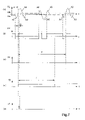
- FIG. 7 shows timing diagrams of certain signals mentioned in FIG. 6 .
- FIG. 8 is a similar view to FIG. 4 , showing a second embodiment.
- FIGS. 1 to 5 show schematically the main elements of a wristwatch according to the invention, in a first embodiment.
- the watch includes a self-winding mechanical watch movement 10 , of a common type such as the Eta 2824 calibre, and an electronic regulator made in the form of an electronic module 11 including a coil 12 which cooperates via electromagnetic coupling with balance 13 of mechanical movement 10 , this balance being the only part altered with respect to the original movement.
- movement 10 is well known, only a few of its components have been shown in the drawings, particularly a spring barrel 14 which drives an escapement wheel 15 via a gear train 16 including a central second wheel 17 , which drives hands 18 of the watch.
- the escapement includes a pallet 19 giving pulses to the mechanical regulator 20 , which includes balance 13 and a balance spring 21 , the regulator being rotatably mounted between plate 22 of movement 10 and a balance-cock 23 fixed to the plate.
- balance-cock 23 is transparent in order to clarify the drawing.
- plate 22 FIG.
- Movement 10 is designed to operate with a usual oscillating frequency of regulator 20 , usual frequencies generally being comprised between 2.5 Hz and 5 Hz, and preferably equal to 3 Hz or 4 Hz. In the examples described here, the theoretical oscillation frequency of regulator 20 is 4 Hz.
- FIG. 2 shows balance 13 in more detail, seen from the side of balance-cock 23 .
- the balance includes a pin 32 , whose ends are mounted in bearings carried by plate 22 and balance-cock 23 , and a flat wheel having a rim 34 , provided with two enlarged parts 35 and 36 each centred on a diametral axis 37 of the balance wheel.
- Part 35 carries two magnets 38 and 39
- part 36 forms a counterweight such that the centre of gravity of the balance is at the centre of its pin 32 .
- Each of magnets 38 and 39 is formed by a small cylindrical disc magnetised parallel to balance pin 32 , but with opposite polarities from one magnet to the other in order to create field lines which pass through the two magnets.
- Rim 34 of the balance is made of a magnetic metal such as iron-nickel, such that its part 35 forms a magnetic shunt which closes the magnetic field created by magnets 38 and 39 on the side of plate 22 .
- balance 13 can have approximately the same external dimensions and the same mass.
- the thickness of rim 34 can be 0.15 mm and that of the magnets 0.25 mm, such that the total thickness of 0.4 mm is the same as that of the balance rim of the original movement.
- Mechanical regulator 20 is arranged to have a slightly higher natural oscillation frequency (for example approximately 1%) than the theoretical frequency of 4 Hz over the entire useful winding range of spring 54 , so that stabilisation of its real frequency by the enslaving circuit can occur just by small braking pulses.
- a simple solution consists in using an identical balance spring to that of the original movement and giving the balance a slightly lower moment of inertia.
- the rate of the mechanical regulator can also be adjusted in the conventional manner, by means of the index.
- mechanical regulator 20 is mounted so that, in a neutral position where balanced spring 21 is at rest, diametral axis 37 and thus the pair of magnets 38 and 39 are opposite coil 12 .
- balance 13 oscillates on either side of this neutral position as arrows A and B of FIG. 2 indicate.
- the amplitude of the oscillator of about ⁇ 270 degrees when the barrel spring is completely wound in a classical movement can be somewhat reduced here for example to about ⁇ 180 degrees by the energy consumption of the electric generator.
- two or several series-connected fixed coils 12 can be provided, cooperating with a corresponding number of pairs of magnets on balance 13 .
- FIG. 3 shows the external appearance of electronic module 11 , whose circuits will be described hereinafter with reference to FIG. 6 . Its components are carried by a printed circuit board 41 having the general shape of a circle segment, in order to be positioned against the lower face of casing ring 26 , to which it is fixed by screws 42 .
- the components shown in FIG. 3 include coil 12 mounted on a part 43 of board 41 that is enlarged in the direction of the inside of the watch, a pair of Schottky diodes 44 and 45 , a pair of capacitors 46 and 47 , a quartz resonator 48 and an integrated circuit 49 .
- Coil 12 is mounted on the top face of board 41 , which holds it in a fixed position, which is chosen such that a slight gap exists between coil 12 and magnets 38 and 39 , typically of the order of 0.2 mm to ensure a strong enough electromagnetic coupling.
- the other elements 44 to 49 are mounted on the bottom face of board 41 , so that they are in usually free space 50 between casing ring 26 and back cover 29 of the case.
- these elements or certain of them could also be arranged on the top face of board 41 , provided that appropriate recesses are arranged in casing ring 26 .
- coil 12 could be mounted on a separate support instead of being directly on board 41 .
- the latter could then be replaced by a flexible film, which could be glued underneath casing ring 26 .
- the configuration of electronic module 11 enables this module to be housed in the watchcase entirely outside mechanical movement 10 , with the exception of coil 12 , which has to be situated facing the rim of balance 13 .
- this coil occupies a space that, in usual mechanical movements, is generally free between balance spring 21 and the periphery of the movement. In certain types of self-winding movements, it may happen that this space is partially occupied by the thick peripheral part of oscillating weight 28 . If one wishes to use the present invention with such a movement, this part of the oscillating weight only has to be slightly altered in order to release sufficient height for coil 12 . Such an alteration is easy and has no repercussions on the other components of the movement, provided that the alteration to the oscillating weight does not reduce the winding torque.
- the watchcase can be identical to that which receives the original mechanical movement.
- the circuits of electronic module 11 described hereinbefore are shown in FIG. 6 and include coil 12 , a rectifier 58 and an enslaving circuit 60 that is made in integrated circuit 49 shown in FIG. 3 .
- Rectifier 58 includes the two Schottky diodes 44 and 45 and the two capacitors 46 and 47 , which are preferably of the ceramic type.
- the inputs of the rectifier are connected to the terminals of coil 12 and its outputs V+, V 0 and V ⁇ power enslaving circuit 60 owing to the electric energy generated by generator 56 and stored in the two capacitors.
- a minimum value of 0.6 V of rectified voltages V+ and V ⁇ , corresponding to the minimum admissible oscillation amplitude of balance 13 is sufficient for integrated circuit 49 to operate, particularly if the latter is made in SOI technology.
- Timing diagram (a) of FIG. 7 shows the evolution of the voltage Ug induced across the terminals of coil 12 by three alternations of balance 13 , each alternation including one passage of the pair of magnets 38 and 39 in front of the coil.
- the first passage during the movement of the balance in a first direction, successively generates three main alternations of voltage Ug, namely one negative alternation A 1 , a positive alternation A 2 and a negative alternation A 3 , then the voltage remains substantially zero while the movement of the balance is completed and changes direction.
- the interruption in the voltage during a brief period tf corresponds to braking which will be described hereinafter.
- Enslaving circuit 60 includes a reference oscillator Osc, driven by quartz resonator 48 to form a time base. Circuit 60 is arranged for enslaving the oscillation frequency of balance 13 to a reference frequency FR derived from oscillator Osc, by carrying out brief oscillator braking operations by short-circuiting coil 12 by means of an electronic switch such as a transistor 62 , in accordance with the principle described in the aforementioned U.S. Pat. Nos. 5,517,469 and 5,740,131. Given that enslaving circuit 60 shown in FIG. 6 is practically the same as that described in EP Patent No. 806 710 (corresponding to U.S. Pat. No. 5,740,131) to which the reader can refer for more details, it will be described in a simplified manner here, while explaining in detail the differences resulting from the present invention.
- One output of timer Tmr delivers, when necessary, a braking pulse IF of duration tf, which makes transistor 62 conductive to short-circuit coil 12 .
- voltage Ug falls to a value close to zero, as can be seen in timing diagram (a) of FIG. 7 .
- Voltage Ug across the terminals of coil 12 is delivered to means for measuring its frequency, including a Schmitt trigger referenced Trig and an inhibition circuit Inh.
- trigger Trig delivers a detection signal IM to the inhibition circuit, which changes sign each time that the absolute value of voltage Ug is sufficiently raised to cross the high voltage threshold Uth or low voltage threshold Utb of the trigger.
- the role of the inhibition circuit Inh is to deliver, for each oscillation period of balance 13 and thus for one out of two passages of the pair of magnets 38 , 39 opposite coil 12 , a measuring pulse IN to the positive input of comparator circuit Cmp and to timer Tmr.
- the measuring pulses IN shown in timing diagram (c) of FIG. 7 , thus theoretically have a frequency f of 4 Hz and a period T of 250 ms, but one can also envisage delivering a measuring pulse IN for each passage of the magnets opposite the coil, thus at a theoretical frequency of 8 Hz.
- inhibition circuit Inh is arranged not to consider the first change of state of signal IM at the instant t 1 indicated in FIG. 7 , but only the second at instant t 2 , to deliver the measuring pulse IN. Otherwise, one could also envisage braking during the first alternation A 1 .
- comparator circuit Cmp The function of comparator circuit Cmp is to indicate, via its output signal AV, whether the oscillation of balance 13 is ahead with respect to that of oscillator OSC.
- This comparator can be for example a reversible counter, which aggregates the difference between the number of measuring pulses IN received at its positive input and the number of reference pulses received at frequency FR at its negative input.
- Timer Tmr receives signal AV and, if the latter indicates that the balance is ahead, it delivers a brief braking signal IF which temporarily makes transistor 62 conductive, which brakes the balance as explained hereinbefore.
- the start of braking signal IF is preferably slightly delayed with respect to the appearance of measuring pulse IN, as is seen in FIG.
- duration tf of braking signal IF is predetermined such that braking occurs in an initial part of the largest alternation A 2 of voltage Ug, but not in the duration where the voltage is highest, since it is at that moment that electric generator 56 can supply most energy to capacitors 46 and 47 .
- timer Tmr starts to deliver to circuit Inh an inhibition signal SI, whose function is to prevent transmission of another measuring pulse IN before the next oscillation period of the balance.
- duration ti of inhibition signal Si is slightly shorter than period T, for example 80% of T.
- the timing diagrams of FIG. 7 correspond to the case in which a single braking operation of duration tf is enough to return the differential count to zero in comparator Cmp, such that there is no new braking during the next voltage alternation A 2 . In the opposite case, braking will occur at each successive period until the number of periods of balance 13 is equal to that of electronic oscillator OSC.
- FIG. 8 is a similar cross-section to FIG. 4 and shows a second embodiment of a watch according to the invention, of which only the differences in relation to the example described hereinbefore will be described, reusing the same reference numerals for the corresponding elements.
- printed circuit board 41 of electronic module 11 is located on the top face of said ring, i.e. on the side of dial 24 .
- Coil 12 and the other components mounted on board 41 are placed on the bottom face of the card, said components occupying recesses (not shown) arranged in casing ring 26 .
- An insulating sheet can be inserted between said ring and the board in the zones where the board is fixed to the ring by screws 42 .
- the operation of the watch is the same as in the first embodiment.
- Balance 13 differs from that of the preceding example solely in that magnets 38 and 39 are placed on the top face of the rim, to pass close to coil 12 located above. Depending upon the original movement used, it may be necessary to make a cut out portion 52 in plate 22 to leave room for coil 12 . This can generally be achieved without any difficulty, since, if the plate of usual movements extends into this region, it is only to shoulder the dial and it usually does not carry there any actual component of the movement.
- the arrangement shown in FIG. 8 can be altered in order to fix electronic module 11 to plate 22 instead of to casing ring 26 .
- cut out portion 52 can be replaced by a recess that occupies only part of the thickness of the plate. Fixing to the plate has the advantage of positioning coil 12 with great precision in relation to balance 13 .
- the application of the present invention is not limited to this subject and extends to any type of timepiece having a mechanical movement provided with a sprung-balance regulator.
Landscapes
- Physics & Mathematics (AREA)
- General Physics & Mathematics (AREA)
- Engineering & Computer Science (AREA)
- Power Engineering (AREA)
- Electromechanical Clocks (AREA)
- Electric Clocks (AREA)
Applications Claiming Priority (2)
| Application Number | Priority Date | Filing Date | Title |
|---|---|---|---|
| EP03022031A EP1521141B1 (de) | 2003-10-01 | 2003-10-01 | Uhr mit einem mechanischen Uhrwerk, das mit einem elektronischen Regulator gekoppelt ist |
| EP03022031.3 | 2003-10-01 |
Publications (2)
| Publication Number | Publication Date |
|---|---|
| US20050036405A1 US20050036405A1 (en) | 2005-02-17 |
| US7306364B2 true US7306364B2 (en) | 2007-12-11 |
Family
ID=34130217
Family Applications (1)
| Application Number | Title | Priority Date | Filing Date |
|---|---|---|---|
| US10/952,939 Expired - Lifetime US7306364B2 (en) | 2003-10-01 | 2004-09-30 | Timepiece having a mechanical movement associated with an electronic regulator |
Country Status (7)
| Country | Link |
|---|---|
| US (1) | US7306364B2 (de) |
| EP (1) | EP1521141B1 (de) |
| JP (1) | JP4722445B2 (de) |
| CN (1) | CN100480902C (de) |
| AT (1) | ATE363675T1 (de) |
| DE (1) | DE60314142T2 (de) |
| SG (1) | SG110187A1 (de) |
Cited By (18)
| Publication number | Priority date | Publication date | Assignee | Title |
|---|---|---|---|---|
| US20090185456A1 (en) * | 2006-07-26 | 2009-07-23 | Xuan Mai Tu | Electromechanical escapement device and timepiece part utilizing such a device |
| EP2095788A1 (de) | 2008-02-29 | 2009-09-02 | Pharmaco-Kinesis Corporation | Medizinische Behandlungsvorrichtung in Form eines künstlichen Zahnes zur Steuerung, Regelung, Messung und Freisetzung von medizinischen Wirkstoffen in den Körper |
| US20100054090A1 (en) * | 2006-12-21 | 2010-03-04 | Franck Orny | Mechanical oscillator for timepiece |
| US20100128573A1 (en) * | 2006-07-11 | 2010-05-27 | Bernardus Johannes Meijer | Clockwork |
| US20100283556A1 (en) * | 2006-04-07 | 2010-11-11 | The Swatch Group Research And Development Ltd | Coupled resonator for regulating system |
| US20150234352A1 (en) * | 2014-02-17 | 2015-08-20 | The Swatch Group Research And Development Ltd | Frequency regulation of a timepiece resonator via action on the active length of a balance spring |
| US9201400B2 (en) * | 2014-02-17 | 2015-12-01 | The Swatch Group Research And Development Ltd | Frequency regulation of a timepiece regulator via action on the rigidity of an elastic return means |
| US20160004223A1 (en) * | 2013-04-10 | 2016-01-07 | The Swatch Group Research And Development Ltd | Winding device for self-winding automatic watch |
| US20170168462A1 (en) * | 2015-12-11 | 2017-06-15 | Samsung Electronics Co., Ltd. | Smart watch including a printed circuit board having a hole at the center |
| EP3330811A1 (de) * | 2016-11-30 | 2018-06-06 | Manufacture Modules Technologies Sarl | Hybrides mechanisches uhrwerk mit integrierter elektronik mit drahtloser kommunikation, sensoren und anzeige |
| US20190187625A1 (en) * | 2017-12-20 | 2019-06-20 | The Swatch Group Research And Development Ltd | Timepiece comprising a mechanical oscillator associated with a regulation system |
| US20190187624A1 (en) * | 2017-12-20 | 2019-06-20 | The Swatch Group Research And Development Ltd. | Timepiece comprising a mechanical oscillator associated with a regulation system |
| US10338527B2 (en) * | 2016-09-27 | 2019-07-02 | The Swatch Group Research And Development Ltd | Self-winding watch |
| US20210109480A1 (en) * | 2019-10-11 | 2021-04-15 | Wisconsin Alumni Research Foundation | Electrical Pulse Generator Harvesting Body Movement Energy |
| US20210191334A1 (en) * | 2019-12-24 | 2021-06-24 | The Swatch Group Research And Development Ltd | Timepiece provided with a mechanical movement and a device for correcting a displayed time |
| US11327440B2 (en) * | 2018-09-27 | 2022-05-10 | The Swatch Group Research And Development Ltd | Timepiece assembly comprising a mechanical oscillator associated with an electronic device for controlling its mean frequency |
| US11480925B2 (en) * | 2017-03-28 | 2022-10-25 | The Swatch Group Research And Development Ltd | Mechanical timepiece comprising a movement which running is enhanced by a regulation device |
| US11537085B2 (en) * | 2019-04-03 | 2022-12-27 | The Swatch Group Research And Development Ltd | Self-adjustable horological oscillator |
Families Citing this family (22)
| Publication number | Priority date | Publication date | Assignee | Title |
|---|---|---|---|---|
| DE602005021748D1 (de) * | 2005-03-30 | 2010-07-22 | Montres Breguet Sa | Uhr mit mindenstens zwei Reguliersystemen |
| US20080013409A1 (en) * | 2006-07-11 | 2008-01-17 | Bland Diarmuid John St Cullom | Timepiece with overlapping, separately driven analog and mechanical functionality |
| ATE532113T1 (de) * | 2006-08-16 | 2011-11-15 | Eta Sa Mft Horlogere Suisse | Elektronisches uhrwerk mit einem resonator |
| CH707005B1 (fr) * | 2012-09-25 | 2023-02-15 | Richemont Int Sa | Mouvement de montre-chronographe avec barillet et régulateur à quartz. |
| CH707471B1 (fr) * | 2013-08-05 | 2014-07-31 | Rd Engineering Rudolf Dinger | Système régulateur pour montre mécanique. |
| EP3156854A1 (de) * | 2015-10-13 | 2017-04-19 | The Swatch Group Research and Development Ltd. | Mechanisches armbanduhr, die mit einer elektronischen funktion assoziert ist |
| BE1024256B1 (nl) * | 2016-06-02 | 2018-01-16 | Mintiens Benoît | Mechanisch uurwerk. |
| EP3339982B1 (de) * | 2016-12-23 | 2021-08-25 | The Swatch Group Research and Development Ltd | Regulierung durch mechanisches bremsen eines mechanischen oszillators einer uhr |
| WO2018177779A1 (fr) * | 2017-03-28 | 2018-10-04 | The Swatch Group Research And Development Ltd | Pièce d'horlogerie comprenant un mouvement mécanique dont la marche est améliorée par un dispositif de correction |
| EP3410236B1 (de) * | 2017-05-29 | 2021-02-17 | The Swatch Group Research and Development Ltd | Vorrichtung und verfahren zum regulieren der ganggenauigkeit und korrigieren des zustands einer armbanduhr |
| EP3410235B1 (de) * | 2017-05-29 | 2020-04-22 | The Swatch Group Research and Development Ltd | Vorrichtung und verfahren zum regulieren der ganggenauigkeit einer armbanduhr |
| EP3432088A1 (de) * | 2017-07-17 | 2019-01-23 | The Swatch Group Research and Development Ltd | Elektromechanische uhr |
| CN110554595B (zh) * | 2018-06-04 | 2022-02-25 | 精工爱普生株式会社 | 电子控制式机械钟表、电子控制式机械钟表的控制方法以及电子钟表 |
| EP3584645B1 (de) * | 2018-06-19 | 2021-06-30 | The Swatch Group Research and Development Ltd | Uhr, die ein mechanisches uhrwerk umfasst, dessen ganggenauigkeit durch eine elektromechanische vorrichtung reguliert wird |
| EP3620867B1 (de) * | 2018-09-04 | 2022-01-05 | The Swatch Group Research and Development Ltd | Uhr, die einen mechanischen oszillator umfasst, dessen durchschnittliche frequenz mit der eines elektronischen referenzoszillators synchronisiert ist |
| CN110209034A (zh) * | 2019-06-01 | 2019-09-06 | 深圳市玺佳创新有限公司 | 一种摆轮印刷手表 |
| EP3748438B1 (de) * | 2019-06-06 | 2022-01-12 | The Swatch Group Research and Development Ltd | Messung der präzision einer uhr, die einen kontinuierlich drehenden elektromechanischen transducer in ihrer analogen uhrzeitanzeigevorrichtung umfasst |
| EP3944027B1 (de) | 2020-07-21 | 2024-06-05 | The Swatch Group Research and Development Ltd | Tragbares gerät, insbesondere armbanduhr, das mit einer stromquellevorrichtung mit einem elektromechanischen wandler ausgestattet ist |
| EP4002018B1 (de) * | 2020-11-12 | 2026-02-25 | The Swatch Group Research and Development Ltd | Intelligente aufziehvorrichtung einer automatischen armbanduhr mit armbanduhridentifikation |
| JP7706984B2 (ja) * | 2021-08-12 | 2025-07-14 | シチズン時計株式会社 | 機械式時計 |
| US20250181035A1 (en) * | 2022-03-14 | 2025-06-05 | Citizen Watch Co., Ltd. | Mechanical timepiece |
| DE102023103852A1 (de) * | 2023-02-16 | 2024-08-22 | Realization Desal Ag | Uhr |
Citations (20)
| Publication number | Priority date | Publication date | Assignee | Title |
|---|---|---|---|---|
| GB880121A (en) | 1958-04-16 | 1961-10-18 | Durowe A G | An electric wristlet watch |
| US3487629A (en) | 1965-02-22 | 1970-01-06 | Citizen Watch Co Ltd | Drive balance wheel arrangement for timepiece |
| US3653199A (en) | 1969-11-10 | 1972-04-04 | Citizen Watch Co Ltd | Coil carrier means in an electronic timepiece movement |
| US3670492A (en) | 1969-05-28 | 1972-06-20 | Citizen Watch Co Ltd | Balance wheel assembly |
| US3676993A (en) * | 1970-08-13 | 1972-07-18 | Hamilton Watch Co | Electronic watch |
| US3787783A (en) | 1971-04-21 | 1974-01-22 | E Ketterer | Time-keeping device with transistor control using oscillating magnet |
| US3937001A (en) | 1972-11-21 | 1976-02-10 | Berney Jean Claude | Watch movement driven by a spring and regulated by an electronic circuit |
| DE3903706A1 (de) | 1988-02-09 | 1989-08-17 | Fraunhofer Ges Forschung | Uhr mit einem elektronischen uhrenbaustein |
| US5278806A (en) * | 1990-10-22 | 1994-01-11 | Gigandet S.A. | Wristwatch |
| US5517469A (en) | 1994-04-25 | 1996-05-14 | Asulab S.A. | Timepiece driven by a source of mechanical energy and regulated by an electric circuit |
| EP0806710A1 (de) | 1996-05-07 | 1997-11-12 | Asulab S.A. | Stabilisation einer elektronischen Schaltung zur Regelung des mechanischen Gangwerks einer Zeitmessvorrichtung |
| US5699322A (en) | 1995-08-10 | 1997-12-16 | Asulab S.A. | Timepiece having a power reserve indicator |
| US5751666A (en) | 1996-08-01 | 1998-05-12 | Asulab S.A. | Electronic timepiece comprising a generator driven by a spring barrel |
| US5835456A (en) | 1996-12-09 | 1998-11-10 | Asulab S.A. | Timepiece including an electric power generator |
| US6021097A (en) * | 1997-03-17 | 2000-02-01 | Citizen Watch Company, Ltd. | Electronic watch provided with an electrical generator |
| US6023446A (en) | 1998-02-05 | 2000-02-08 | Asulab S.A. | Timepiece comprising a generator driven by the main spring of a barrel |
| US6113259A (en) | 1997-04-28 | 2000-09-05 | Asulab S.A. | Electronic timepiece supplied by a generator driven by a mechanical power source |
| EP1093036A1 (de) | 1999-04-28 | 2001-04-18 | Seiko Instruments Inc. | Mechanischer zeitmesser mit drehwinkelsteuermechanismus mit synchronisierter ringunruh |
| EP1143307A1 (de) | 1999-11-11 | 2001-10-10 | Seiko Instruments Inc. | Mechanische uhr mit einem steuermechanismus des drehungswinkels von der regulierten ringunruh |
| US7016265B2 (en) * | 2003-10-01 | 2006-03-21 | Asulab S.A. | Timepiece having a mechanical movement associated with an electronic regulator |
Family Cites Families (2)
| Publication number | Priority date | Publication date | Assignee | Title |
|---|---|---|---|---|
| JP2857839B2 (ja) * | 1994-12-08 | 1999-02-17 | セイコークロック株式会社 | 電動式指針修正装置付時計 |
| JP2002318291A (ja) * | 2001-04-20 | 2002-10-31 | Rhythm Watch Co Ltd | 時計装置 |
-
2003
- 2003-10-01 AT AT03022031T patent/ATE363675T1/de not_active IP Right Cessation
- 2003-10-01 EP EP03022031A patent/EP1521141B1/de not_active Expired - Lifetime
- 2003-10-01 DE DE60314142T patent/DE60314142T2/de not_active Expired - Lifetime
-
2004
- 2004-09-27 SG SG200405602A patent/SG110187A1/en unknown
- 2004-09-30 US US10/952,939 patent/US7306364B2/en not_active Expired - Lifetime
- 2004-09-30 CN CNB2004100852169A patent/CN100480902C/zh not_active Expired - Lifetime
- 2004-10-01 JP JP2004289802A patent/JP4722445B2/ja not_active Expired - Lifetime
Patent Citations (22)
| Publication number | Priority date | Publication date | Assignee | Title |
|---|---|---|---|---|
| GB880121A (en) | 1958-04-16 | 1961-10-18 | Durowe A G | An electric wristlet watch |
| US3487629A (en) | 1965-02-22 | 1970-01-06 | Citizen Watch Co Ltd | Drive balance wheel arrangement for timepiece |
| US3670492A (en) | 1969-05-28 | 1972-06-20 | Citizen Watch Co Ltd | Balance wheel assembly |
| US3653199A (en) | 1969-11-10 | 1972-04-04 | Citizen Watch Co Ltd | Coil carrier means in an electronic timepiece movement |
| US3676993A (en) * | 1970-08-13 | 1972-07-18 | Hamilton Watch Co | Electronic watch |
| US3787783A (en) | 1971-04-21 | 1974-01-22 | E Ketterer | Time-keeping device with transistor control using oscillating magnet |
| US3937001A (en) | 1972-11-21 | 1976-02-10 | Berney Jean Claude | Watch movement driven by a spring and regulated by an electronic circuit |
| CH597636B5 (de) | 1972-11-21 | 1978-04-14 | Ebauches Sa | |
| DE3903706A1 (de) | 1988-02-09 | 1989-08-17 | Fraunhofer Ges Forschung | Uhr mit einem elektronischen uhrenbaustein |
| US5278806A (en) * | 1990-10-22 | 1994-01-11 | Gigandet S.A. | Wristwatch |
| US5517469A (en) | 1994-04-25 | 1996-05-14 | Asulab S.A. | Timepiece driven by a source of mechanical energy and regulated by an electric circuit |
| US5699322A (en) | 1995-08-10 | 1997-12-16 | Asulab S.A. | Timepiece having a power reserve indicator |
| EP0806710A1 (de) | 1996-05-07 | 1997-11-12 | Asulab S.A. | Stabilisation einer elektronischen Schaltung zur Regelung des mechanischen Gangwerks einer Zeitmessvorrichtung |
| US5740131A (en) | 1996-05-07 | 1998-04-14 | Asulab S.A. | Stabilising of an electronic circuit for regulating a mechanical movement of a timepiece |
| US5751666A (en) | 1996-08-01 | 1998-05-12 | Asulab S.A. | Electronic timepiece comprising a generator driven by a spring barrel |
| US5835456A (en) | 1996-12-09 | 1998-11-10 | Asulab S.A. | Timepiece including an electric power generator |
| US6021097A (en) * | 1997-03-17 | 2000-02-01 | Citizen Watch Company, Ltd. | Electronic watch provided with an electrical generator |
| US6113259A (en) | 1997-04-28 | 2000-09-05 | Asulab S.A. | Electronic timepiece supplied by a generator driven by a mechanical power source |
| US6023446A (en) | 1998-02-05 | 2000-02-08 | Asulab S.A. | Timepiece comprising a generator driven by the main spring of a barrel |
| EP1093036A1 (de) | 1999-04-28 | 2001-04-18 | Seiko Instruments Inc. | Mechanischer zeitmesser mit drehwinkelsteuermechanismus mit synchronisierter ringunruh |
| EP1143307A1 (de) | 1999-11-11 | 2001-10-10 | Seiko Instruments Inc. | Mechanische uhr mit einem steuermechanismus des drehungswinkels von der regulierten ringunruh |
| US7016265B2 (en) * | 2003-10-01 | 2006-03-21 | Asulab S.A. | Timepiece having a mechanical movement associated with an electronic regulator |
Non-Patent Citations (1)
| Title |
|---|
| European Search Report, completed May 14, 2004. |
Cited By (28)
| Publication number | Priority date | Publication date | Assignee | Title |
|---|---|---|---|---|
| US20100283556A1 (en) * | 2006-04-07 | 2010-11-11 | The Swatch Group Research And Development Ltd | Coupled resonator for regulating system |
| US7889028B2 (en) | 2006-04-07 | 2011-02-15 | The Swatch Group Research And Development Ltd | Coupled resonator for regulating system |
| US20100128573A1 (en) * | 2006-07-11 | 2010-05-27 | Bernardus Johannes Meijer | Clockwork |
| US7891862B2 (en) * | 2006-07-26 | 2011-02-22 | Isa France S.A. | Electromechanical escapement device and timepiece part utilizing such a device |
| US20090185456A1 (en) * | 2006-07-26 | 2009-07-23 | Xuan Mai Tu | Electromechanical escapement device and timepiece part utilizing such a device |
| US20100054090A1 (en) * | 2006-12-21 | 2010-03-04 | Franck Orny | Mechanical oscillator for timepiece |
| US8240910B2 (en) * | 2006-12-21 | 2012-08-14 | Complitime S.A. | Mechanical oscillator for timepiece |
| EP2095788A1 (de) | 2008-02-29 | 2009-09-02 | Pharmaco-Kinesis Corporation | Medizinische Behandlungsvorrichtung in Form eines künstlichen Zahnes zur Steuerung, Regelung, Messung und Freisetzung von medizinischen Wirkstoffen in den Körper |
| US20160004223A1 (en) * | 2013-04-10 | 2016-01-07 | The Swatch Group Research And Development Ltd | Winding device for self-winding automatic watch |
| US9836027B2 (en) * | 2013-04-10 | 2017-12-05 | The Swatch Group Research And Development Ltd | Winding device for self-winding automatic watch |
| US20150234352A1 (en) * | 2014-02-17 | 2015-08-20 | The Swatch Group Research And Development Ltd | Frequency regulation of a timepiece resonator via action on the active length of a balance spring |
| US9354607B2 (en) * | 2014-02-17 | 2016-05-31 | The Swatch Group Research And Development Ltd | Frequency regulation of a timepiece resonator via action on the active length of a balance spring |
| US9201400B2 (en) * | 2014-02-17 | 2015-12-01 | The Swatch Group Research And Development Ltd | Frequency regulation of a timepiece regulator via action on the rigidity of an elastic return means |
| US20170168462A1 (en) * | 2015-12-11 | 2017-06-15 | Samsung Electronics Co., Ltd. | Smart watch including a printed circuit board having a hole at the center |
| US10001756B2 (en) * | 2015-12-11 | 2018-06-19 | Samsung Electronics Co., Ltd. | Smart watch including a printed circuit board having a hole at the center |
| US10338527B2 (en) * | 2016-09-27 | 2019-07-02 | The Swatch Group Research And Development Ltd | Self-winding watch |
| EP3330811A1 (de) * | 2016-11-30 | 2018-06-06 | Manufacture Modules Technologies Sarl | Hybrides mechanisches uhrwerk mit integrierter elektronik mit drahtloser kommunikation, sensoren und anzeige |
| US11480925B2 (en) * | 2017-03-28 | 2022-10-25 | The Swatch Group Research And Development Ltd | Mechanical timepiece comprising a movement which running is enhanced by a regulation device |
| US20190187624A1 (en) * | 2017-12-20 | 2019-06-20 | The Swatch Group Research And Development Ltd. | Timepiece comprising a mechanical oscillator associated with a regulation system |
| US20190187625A1 (en) * | 2017-12-20 | 2019-06-20 | The Swatch Group Research And Development Ltd | Timepiece comprising a mechanical oscillator associated with a regulation system |
| US11846915B2 (en) * | 2017-12-20 | 2023-12-19 | The Swatch Group Research And Development Ltd | Timepiece comprising a mechanical oscillator associated with a regulation system |
| US11868092B2 (en) * | 2017-12-20 | 2024-01-09 | The Swatch Group Research And Development Ltd | Timepiece comprising a mechanical oscillator associated with a regulation system |
| US11327440B2 (en) * | 2018-09-27 | 2022-05-10 | The Swatch Group Research And Development Ltd | Timepiece assembly comprising a mechanical oscillator associated with an electronic device for controlling its mean frequency |
| US11537085B2 (en) * | 2019-04-03 | 2022-12-27 | The Swatch Group Research And Development Ltd | Self-adjustable horological oscillator |
| US20210109480A1 (en) * | 2019-10-11 | 2021-04-15 | Wisconsin Alumni Research Foundation | Electrical Pulse Generator Harvesting Body Movement Energy |
| US11988992B2 (en) * | 2019-10-11 | 2024-05-21 | Wisconsin Alumni Research Foundation | Electrical pulse generator harvesting body movement energy |
| US20210191334A1 (en) * | 2019-12-24 | 2021-06-24 | The Swatch Group Research And Development Ltd | Timepiece provided with a mechanical movement and a device for correcting a displayed time |
| US11586150B2 (en) * | 2019-12-24 | 2023-02-21 | The Swatch Group Research And Development Ltd | Timepiece provided with a mechanical movement and a device for correcting a displayed time |
Also Published As
| Publication number | Publication date |
|---|---|
| JP4722445B2 (ja) | 2011-07-13 |
| JP2005106830A (ja) | 2005-04-21 |
| EP1521141B1 (de) | 2007-05-30 |
| CN1603981A (zh) | 2005-04-06 |
| EP1521141A1 (de) | 2005-04-06 |
| DE60314142T2 (de) | 2008-01-24 |
| US20050036405A1 (en) | 2005-02-17 |
| SG110187A1 (en) | 2005-04-28 |
| ATE363675T1 (de) | 2007-06-15 |
| DE60314142D1 (de) | 2007-07-12 |
| HK1075299A1 (zh) | 2005-12-09 |
| CN100480902C (zh) | 2009-04-22 |
Similar Documents
| Publication | Publication Date | Title |
|---|---|---|
| US7306364B2 (en) | Timepiece having a mechanical movement associated with an electronic regulator | |
| US7016265B2 (en) | Timepiece having a mechanical movement associated with an electronic regulator | |
| KR100605775B1 (ko) | 전자 시계 및 전자 기기 | |
| US8534910B2 (en) | Regulating member for a wristwatch, and timepiece comprising such a regulating member | |
| US20240272588A1 (en) | Mechanical Watch | |
| US6327225B1 (en) | Electronic unit, and control method for electronic unit | |
| US5025428A (en) | Electromagnetic escapement for mechanically driven watch or clock | |
| JPH058397B2 (de) | ||
| JP3024482B2 (ja) | アナログ電子時計及びその充電方法 | |
| CN114787723B (zh) | 带有机械机芯和用于校正显示时间的校正装置的时计 | |
| US11402804B2 (en) | Timepiece oscillator insensitive to angular acceleration caused by wear | |
| HK1075706B (en) | Timepiece having a mechanical movement associated with an electronic regulator | |
| HK1075299B (en) | Timepiece having a mechanical movement associated with an electronic regulator | |
| JPS58179379A (ja) | 電子時計 | |
| US3808792A (en) | Drive mechanism of an electric timepiece | |
| US3667210A (en) | Horological instrument | |
| US3224183A (en) | Electrically actuated time integrating device | |
| JP4581443B2 (ja) | 暦表示機能付電子時計 | |
| US3693342A (en) | Tuning-fork type electronic clock | |
| HK40092379A (zh) | 包括表和用於校正时间的系统的时计组件 | |
| HK40078474B (zh) | 带有机械机芯和用於校正显示时间的校正装置的时计 | |
| JP2000214271A (ja) | 電子制御式電子機器、電子制御式機械時計および電子制御式電子機器の制御方法 | |
| JPH10142357A (ja) | 発電装置付き電子時計 | |
| JPWO2001048567A1 (ja) | てんぷ発電制御機構付き機械式時計 | |
| JP2005233791A (ja) | 暦表示機能付電子時計及びその制御方法 |
Legal Events
| Date | Code | Title | Description |
|---|---|---|---|
| AS | Assignment |
Owner name: ASULAB S.A., SWITZERLAND Free format text: ASSIGNMENT OF ASSIGNORS INTEREST;ASSIGNORS:BORN, JEAN-JACQUES;FARINE, PIERRE-ANDRE;REEL/FRAME:015859/0835 Effective date: 20040906 |
|
| STCF | Information on status: patent grant |
Free format text: PATENTED CASE |
|
| FPAY | Fee payment |
Year of fee payment: 4 |
|
| FPAY | Fee payment |
Year of fee payment: 8 |
|
| AS | Assignment |
Owner name: THE SWATCH GROUP RESEARCH AND DEVELOPMENT LTD, SWI Free format text: MERGER;ASSIGNOR:ASULAB S.A.;REEL/FRAME:044989/0933 Effective date: 20170509 |
|
| MAFP | Maintenance fee payment |
Free format text: PAYMENT OF MAINTENANCE FEE, 12TH YEAR, LARGE ENTITY (ORIGINAL EVENT CODE: M1553); ENTITY STATUS OF PATENT OWNER: LARGE ENTITY Year of fee payment: 12 |