US7522090B2 - Systems and methods for a terrain contour matching navigation system - Google Patents
Systems and methods for a terrain contour matching navigation system Download PDFInfo
- Publication number
- US7522090B2 US7522090B2 US11/554,802 US55480206A US7522090B2 US 7522090 B2 US7522090 B2 US 7522090B2 US 55480206 A US55480206 A US 55480206A US 7522090 B2 US7522090 B2 US 7522090B2
- Authority
- US
- United States
- Prior art keywords
- correlation
- reference basket
- array
- sample point
- altitude
- Prior art date
- Legal status (The legal status is an assumption and is not a legal conclusion. Google has not performed a legal analysis and makes no representation as to the accuracy of the status listed.)
- Active, expires
Links
- 238000000034 method Methods 0.000 title claims abstract description 86
- 238000005314 correlation function Methods 0.000 claims description 10
- 230000006870 function Effects 0.000 claims description 5
- 230000000875 corresponding effect Effects 0.000 claims 3
- 230000002596 correlated effect Effects 0.000 claims 1
- 238000004364 calculation method Methods 0.000 description 2
- 238000010586 diagram Methods 0.000 description 2
- 230000006978 adaptation Effects 0.000 description 1
- 238000003491 array Methods 0.000 description 1
- 238000010923 batch production Methods 0.000 description 1
- 238000013500 data storage Methods 0.000 description 1
- 238000005259 measurement Methods 0.000 description 1
- 230000005055 memory storage Effects 0.000 description 1
- 239000000203 mixture Substances 0.000 description 1
- 230000003287 optical effect Effects 0.000 description 1
- 239000002699 waste material Substances 0.000 description 1
Images



Classifications
-
- G—PHYSICS
- G01—MEASURING; TESTING
- G01C—MEASURING DISTANCES, LEVELS OR BEARINGS; SURVEYING; NAVIGATION; GYROSCOPIC INSTRUMENTS; PHOTOGRAMMETRY OR VIDEOGRAMMETRY
- G01C21/00—Navigation; Navigational instruments not provided for in groups G01C1/00 - G01C19/00
- G01C21/10—Navigation; Navigational instruments not provided for in groups G01C1/00 - G01C19/00 by using measurements of speed or acceleration
- G01C21/12—Navigation; Navigational instruments not provided for in groups G01C1/00 - G01C19/00 by using measurements of speed or acceleration executed aboard the object being navigated; Dead reckoning
- G01C21/16—Navigation; Navigational instruments not provided for in groups G01C1/00 - G01C19/00 by using measurements of speed or acceleration executed aboard the object being navigated; Dead reckoning by integrating acceleration or speed, i.e. inertial navigation
- G01C21/165—Navigation; Navigational instruments not provided for in groups G01C1/00 - G01C19/00 by using measurements of speed or acceleration executed aboard the object being navigated; Dead reckoning by integrating acceleration or speed, i.e. inertial navigation combined with non-inertial navigation instruments
- G01C21/1652—Navigation; Navigational instruments not provided for in groups G01C1/00 - G01C19/00 by using measurements of speed or acceleration executed aboard the object being navigated; Dead reckoning by integrating acceleration or speed, i.e. inertial navigation combined with non-inertial navigation instruments with ranging devices, e.g. LIDAR or RADAR
-
- G—PHYSICS
- G01—MEASURING; TESTING
- G01C—MEASURING DISTANCES, LEVELS OR BEARINGS; SURVEYING; NAVIGATION; GYROSCOPIC INSTRUMENTS; PHOTOGRAMMETRY OR VIDEOGRAMMETRY
- G01C21/00—Navigation; Navigational instruments not provided for in groups G01C1/00 - G01C19/00
- G01C21/005—Navigation; Navigational instruments not provided for in groups G01C1/00 - G01C19/00 with correlation of navigation data from several sources, e.g. map or contour matching
Definitions
- Unmanned aircraft often use a terrain contour matching (TERCOM) navigation system that compares altitude samples with an on-board contour map of the terrain to determine the aircrafts position.
- a typical TERCOM navigation system first collects a sequence of altitude samples measured by devices such as a radar altimeter or laser altimeter. The altitude samples are then assembled into a two-dimensional array that associates a horizontal position (e.g. a longitude and latitude) with each of the altitude samples.
- the TERCOM navigation system also includes a contour map of a region of terrain that associates altitudes with two-dimensional horizontal positions.
- the TERCOM navigation system establishes a first reference point that represents the aircraft's position based on the two-dimensional array, while establishing a second reference point that represents the aircraft's position based on the contour map.
- the TERCOM navigation system then correlates a selected area from the contour map (hereinafter referred to as the selected reference basket) across the entire sequence of altitude samples to achieve a best fit solution.
- the aircraft's position error is then determined based on any resulting delta between the first and second reference points. If there is no position error, then the first and second reference points will correspond to the same point from the best fit solution. If the aircraft is off in one or both of the latitude direction or the longitude direction, there will be a corresponding offset between the reference points.
- the traditional TERCOM navigation system correlates the reference map across the entire sequence of altitude samples to achieve a best fit solution.
- This traditional TERCOM technique results in two problems. First, to calculate the position error using a correlation algorithm, the TERCOM navigation system must batch process the entire sequence of altitude samples at once. This batch processing of the sample points results in significant processor loading while the algorithm is executed, and further results in a delay (2-3 seconds, for example) before a position error estimate is available to the aircraft for making any required course correction. Second, the portion of the contour map used to perform the correlation must be pre-selected based on a pre-flight plan. If the reference map is too large, the correlation algorithm will waste time and processor resources needlessly calculating a best fit solution for areas of the terrain that are not relevant.
- the size of the reference map is largely based on the expected position error.
- the greater the expected error the larger the correlation area provided by the reference map needs to be.
- the less the expected error the smaller the correlation area provided by the reference map needs to be.
- One additional factor that must also be considered in selecting the size of reference map is the expected terrain slope variation.
- the terrain slope variation dictates how much information is provided by an area of terrain. For example a terrain comprising mostly desert is relatively smooth and provides limited variations in terrain slope. Thus one area of the desert terrain's surface provides little information to distinguish it from another. In contrast, a mountainous terrain provides many variations in terrain slope.
- a reference map covering a desert terrain must be relatively larger than a reference map covering a mountainous terrain in order for the correlation algorithm to be sure to converge on a best fit solution.
- these traditional TERCOM navigation systems must be pre-programmed with a predetermined flight plan in order to know the type of terrain the aircraft will fly over and thus select the correct size reference map for correlating.
- Embodiments of the present invention provide methods and systems for improved systems and methods for TERCOM navigation and will be understood by reading and studying the following specification.
- a method for terrain contour matching navigation comprises: receiving at least one sample point representing the position of an aircraft, the at least one sample point including a horizontal position and an altitude sample; correlating a first sample point of the at least one sample point across a reference basket array having a plurality of elements; determining a correlation quality; when the correlation quality does not achieve a pre-determined quality threshold, performing at least one additional correlation of an additional sample point of the at least one sample point across the reference basket array; and when the correlation quality does achieve a pre-determined quality threshold, calculating a position error based on the correlating of the first sample point and any additional correlations of any additional sample points.
- FIG. 1 is a block diagram illustrating an improved TERCOM navigation system of one embodiment of the present invention
- FIG. 2 is a flow chart illustrating a method of one embodiment of the present invention
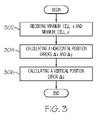
- FIG. 3 is a flow chart illustrating a method of one embodiment of the present invention.
- FIG. 4 is a flow chart illustrating a method of one embodiment of the present invention.
- FIG. 1 is a block diagram illustrating an improved TERCOM navigation system 100 for an aircraft 101 of one embodiment of the present invention.
- TERCOM navigation system 100 comprises a inertial navigation system 110 , a clearance altimeter 120 and a memory 130 , each coupled to a processor 140 .
- Inertial navigation system 110 comprises one or more gyroscopes 111 , one or more accelerometers 112 , and an altimeter 113 .
- inertial navigation system 110 Based on measurements provided by the one or more gyroscopes 111 , one or more accelerometers 112 , and an altimeter 113 , inertial navigation system 110 produces and outputs a navigation solution that includes a two-dimensional (in terms of longitude and latitude, for example) horizontal position of the aircraft 101 and a vertical inertial altitude of the aircraft 101 (shown as Alt i ) in units of distance above a reference surface.
- the reference surface could include a theoretical surface, such as but not limited to an average or mean sea level, for example.
- inertial navigation system 110 further comprises a Kalman filter 114 .
- Kalman filter as used in a navigation system is a filter algorithm implemented in a digital computer system that acts to filter and blend data from navigation sensors having varying degrees of accuracy, in order to establish an optimal estimate of an aircraft's navigation state.
- Kalman filter 114 receives inertial data from gyroscopes 111 , accelerometers 112 , and altimeter 113 , calculates an estimate of the aircraft's navigation state, which is provided as inertial navigation system 100 's navigation solution, and also calculates error estimates associated with the navigation solution output.
- Clearance altimeter 120 measures the distance between the aircraft 101 and the surface of the terrain (not shown) over which the aircraft 101 is flying. The distance is typically referred to as the aircraft's clearance altitude and is illustrated in FIG. 1 as Alt c .
- clearance altimeter 120 may comprise a radar altimeter, a laser altimeter or a combination of the two.
- other means for determining the clearance altitude (Alt c ) may be used to implement clearance altimeter 120 .
- Memory 130 is a memory device programmed with a contour map 132 of the terrain over which the aircraft 101 travels.
- the contour map 132 comprises an array of values that provides the altitude of a point located at a specific horizontal position on the terrain.
- Processor 140 receives the latitude, longitude and inertial altitude (Alt i ) navigation solution data from inertial navigation system 110 and the clearance altitude (Alt c ) from clearance altimeter 120 . Subtracting the clearance altitude (Alt c ) from the inertial altitude (Alt i ) (shown at 142 ), processor 140 calculates an estimated altitude of the surface of the terrain above the reference surface (shown in FIG. 1 as altitude sample Alt m ). For example, in one embodiment, the altitude sample Alt m represents an estimate of the terrain's surface above sea level at a specific latitude and longitude.
- Alt m calculated for a specific latitude and longitude, along with those latitude and longitude values define what is referred to herein as a single sample point, shown in FIG. 1 at 144 as (latitude, longitude, Alt m ).
- Processor 140 further comprises a reference basket selector 141 .
- the reference basket is an area of the surfaced terrain under the aircraft 101 , as mapped by the contour map in memory 130 , that includes the longitude and latitude point provided by inertial navigation system 110 and also includes an area around that point based on the uncertainty in the longitude and latitude information. For example, if the predicted uncertainty is +/ ⁇ 50 meters in the longitude direction and +/ ⁇ 100 meters in the latitude direction, reference basket selector 142 selects a reference basket from the contour map in memory 130 that includes at least the longitude and latitude point and all points in the area of the rectangle formed from 50 meters north to 50 meters south of the longitude and 100 meters east to 100 meters west of the latitude. The reference basket selector 141 then provides the reference basket location and size to correlation function 143 .
- reference basket selector 141 includes and error estimator 145 that determines the uncertainty in the longitude and latitude information provided by inertial navigation system 110 .
- error estimator 145 receives an estimator quality signal from Kalman filter 114 and determines an uncertainty in the longitude and latitude information based on error estimates calculated by Kalman filter 114 .
- error estimator 145 determines the uncertainty in the longitude and latitude information from inertial navigation system 110 using a constant assumed error which is based on known error characteristics of the equipment used to implement inertial navigation system 110 .
- correlation function 143 selects a reference basket array from the contour map 132 in memory 130 .
- the reference basket array comprises an array having elements populated by altitude (Alt m ′) values for each longitude and latitude point located within the reference basket area determined by reference basket selector 142 .
- Altitude Alt m ′
- the reference basket array is an array having dimensions of x elements by y elements. In other embodiments, other reference basket area shapes are contemplated as within the scope of the present invention.
- Correlation function 143 correlates the sample point (latitude, longitude, Alt m ) over the entire area of the reference basket (that is, it correlates the sample point against each element in the reference basket array). As explained in greater detail below, the result of this correlation enables navigation system 100 to determine any differences between the horizontal position of aircraft 101 as provided by inertial navigation system 110 and the horizontal position of aircraft 101 as indicated by the contour map 132 . These differences are computed by processor 140 using position error output function 146 . In operation, correlation function 143 correlates a sample point against the reference basket array and identifies an element within the reference basket array corresponding to a smallest computed correlation value. Two methods for computing the correlation value include the minimum variance technique (described below with respect to FIG.
- correlation function 143 inputs additional sample points, one at a time as required, sequentially correlating each sample point against the same reference basket array until a correlation of sufficient quality is achieved.
- position error output function 146 calculates horizontal position errors ⁇ x and ⁇ y, and vertical position error ⁇ z based on the element within the reference basket array corresponding with the smallest computed correlation value.
- FIG. 2 is a flow chart illustrating a method of one embodiment of the present invention that correlates a sample point against the area of a reference basket as represented by a reference basket array.
- the method of FIG. 2 is implemented by correlation function 143 .
- the method of FIG. 2 determines the difference between the Alt m value of the sample point and the Alt m ′ values contained in the reference basket array, and subsequently identifies the element having the minimum standard deviation within the reference basket array.
- the element having the minimum standard deviation corresponds to a predicted navigator position (that is, a most probable navigator position) relative to the reference basket area. It is understood that the method of FIG. 2 illustrates just one of many possible algorithms for identifying a predicted navigator position based on minimum variance that are embodied within the claims of the present invention.
- the method begins at 202 with receiving a sample point (latitude, longitude, Alt m ) and incrementing a sample point counter (n) by one (shown at 204 ).
- the method implements two indexing loops that step the method through each element of a rectangular reference basket array having dimensions of x elements by y elements. It would be appreciated by one of ordinary skill in the art upon reading this specification that in embodiment utilizing non-rectangular reference basket shapes, other ways are available for stepping the method through each element of the non-rectangular reference basket array representing the non-rectangular reference basket.
- the first loop (shown starting a block 206 ) steps the method by increasing index value i from 1 to x, where x is equal to the number of columns of the reference basket array.
- the second loop (shown starting a block 208 ) steps the method by increasing index value j from 1 to y, where y is equal to the number of rows of the reference basket array.
- the method proceeds to 210 with computing the difference between the value of Alt m ′(i,j) of the reference basket array and the Alt m value from the sample point received at block 202 (shown as difference[Alt m ⁇ Alt m ′(i,j)] in block 210 ).
- the method of FIG. 2 performs a sequential computation at block 212 to determine a correlation value standard deviation for each element of the reference basket array.
- the minimum correlation value standard deviation calculated corresponds to the predicted (that is, the most probable) navigator position relative to the reference basket area. Accordingly, the method of FIG. 2 proceeds to 214 with determining whether the correlation_value_standard_deviation(i,j) value for the current index position (i,j) is the minimum value calculated so far. In one embodiment, when the correlation_value_standard_deviation(i,j) value for the current index position (i,j) is the minimum value calculated so far, the method sets the value of variable minimum_cell_x equal to the current value of i, and the value of variable minimum_cell_y equal to the current value of j (shown at block 216 ). The method then loops back to 208 and 206 , incrementing the index values of j and i, respectively and repeating steps 210 , 212 , 214 and 216 until the loops are completed.
- the resulting values of minimum_cell_x and minimum_cell_y identify the elements of the reference basket array that most probably represents the navigator position relative to the reference basket area, based on the correlation of n sample points. Whether these resulting values should be used for computing a position error depends on the quality of the correlation. If the correlation quality is sufficient (determined at block 220 ) then the values of minimum_cell_x and minimum_cell_y are used to calculate a position error as shown in FIG. 3 and discussed in further detail below. If the correlation quality is not sufficient, then further correlation with another sample point is required.
- the method begins at 202 with receiving another sample point (latitude, longitude, Alt m ), incrementing the value of n by one (at 204 ) and repeating the process of loops 206 and 208 .
- the same reference basket area and reference basket array are used for calculation of the first, second, and any subsequent correlations until a satisfactory correlation is achieved.
- the values of difference_sum(i,j) and difference_sum_squared(i,j) are not reset until a satisfactory correlation is achieved. Whether a particular correlation is of satisfactory quality is readily determined by one of ordinary skill in the art upon reading this specification based on the particular accuracy required to satisfy the goals and mission of the aircraft 101 .
- the terrain slope variation plays a role in how much information is provided by an area of terrain.
- a terrain comprising mostly smooth desert provides limited variations in terrain slope and may require several sample points before achieving a correlation of satisfactory quality.
- a mountainous terrain provides many variations in terrain slope and would be expect to achieve a correlation of satisfactory quality with relatively fewer sample points.
- a correlation of sufficient quality is deemed to be achieved when the minimum calculated correlation_value_standard_deviation(i,j) achieves a predetermined threshold.
- an x by y array comprising the values of correlation_value_standard_deviation(i,j) defines a “correlation surface” that represents the quality of the correlation achieved by the method of FIG. 2 .
- a minimum point in the surface will develop in a region around the values of i and j corresponding to the values of minimum_cell_x and minimum_cell_y for each correlation.
- a correlation of sufficient quality is deemed to be achieved when the slope of the region around the minimum point achieves a predetermined threshold.
- FIG. 3 is a flow chart illustrating a method of one embodiment of the present invention for calculating a position error based on the results of a correlation, of one embodiment of the present invention.
- the method of FIG. 3 is implemented by a position error output function 146 as shown in FIG. 1 .
- the method begins at 302 with receiving the values of minimum_cell_x and minimum_cell_y from a correlation, when a correlation of sufficient quality is achieved, which correspond with the elements of the reference basket array that most probably represents the navigator position relative to the reference basket area.
- the method determines the horizontal position error in the two dimensions of x and y.
- x and y may be in the form of latitude and longitude values, other coordinate reference frames may be utilized. Accordingly, the method proceeds to 304 with calculating the horizontal position error.
- the correlation method of that produces the minimum_cell_x and minimum_cell_y values also provides sufficient information for calculating a vertical position error ⁇ z, that represents a position error in terms of altitude.
- a vertical position error ⁇ z that represents a position error in terms of altitude.
- the method proceeds to 306 .
- the ⁇ x, ⁇ y and ⁇ z position errors calculated by position error output function 146 using the method of FIG. 3 are provided to inertial navigation system 110 as correction factors to increase the accuracy of the navigation solution provided by inertial navigation system 110 .
- the minimum absolute deviation (MAD) correlation technique involves subtracting a constant (representing a bias) from the difference between the Alt m value of the sample point and the Alt m ′ values contained in the reference basket array and taking the absolute value of the result. A running sum of the result is kept for each cell in the basket area, and the element having the minimum value at the end of the correlation corresponds to the predicted (that is, the most probable) navigator position relative to the basket area.
- the correlation one or more sample points may be required to achieve a correlation of sufficient quality to subsequently calculate ⁇ x, ⁇ y and ⁇ z position errors.
- the constant represents the sum of any sensor bias, any bias is the value of Alt m and any bias in the Alt m ′ values contained in the reference basket array.
- the bias constant is computed from known values of these biases.
- the bias constant used in the method of FIG. 4 can be derived from a previously performed minimum variance correlation, such as shown in FIG. 2 , which is insensitive to biases.
- FIG. 4 is a flow chart illustrating a method of one embodiment of the present invention that correlates a sample point against the area of a reference basket as represented by a reference basket array using a MAD correlation technique.
- the method of FIG. 4 is implemented by correlation function 143 .
- the method of FIG. 4 determines the difference between the Alt m value of the sample point and the Alt m ′ values contained in the reference basket array, and subsequently identifies the element having the minimum absolute deviation within the reference basket array.
- the element having the minimum absolute deviation corresponds to the predicted (that is, the most probable) navigator position relative to the reference basket area. It is understood that the method of FIG. 4 illustrates just one of many possible algorithms for identifying a most probable navigator position based on minimum absolute deviation that are embodied within the claims of the present invention.
- the method begins at 402 with receiving a sample point (latitude, longitude, Alt m ) and incrementing a sample point counter (n) by one (shown at 404 ).
- the method implements two indexing loops that step the method through each element of a rectangular reference basket array having dimensions of x elements by y elements.
- embodiments of the present invention are not limited to rectangular reference basket area but include methods that correlate a sample point against non-rectangular reference baskets.
- the first loop (shown starting a block 406 ) steps the method by increasing index value i from 1 to x, where x is equal to the number of columns of the reference basket array.
- the second loop (shown starting a block 408 ) steps the method by increasing index value j from 1 to y, where y is equal to the number of rows of the reference basket array.
- the method proceeds to 410 with computing the difference between the value of Alt m ′(i,j) of the reference basket array and the Alt m value from the sample point received at block 402 (shown as difference[Alt m ⁇ Alt m ′(i,j)] in block 410 ).
- the method proceeds to block 412 with determining a correlation value minimum absolute deviation for each element of the reference basket array.
- the minimum correlation value minimum absolute deviation calculated corresponds to the most probable navigator position relative to the reference basket area. Accordingly, the method of FIG. 4 proceeds to 414 with determining whether the correlation_value_MAD (i,j) value for the current index position (i,j) is the minimum value calculated so far. In one embodiment, when the correlation_value_MAD (i,j) value for the current index position (i,j) is the minimum value calculated so far, the method sets the value of variable minimum_cell_x equal to the current value of i, and the value of variable minimum_cell_y equal to the current value of j (shown at block 416 ). The method then loops back to 408 and 406 , incrementing the index values of j and i, respectively and repeating steps 410 , 412 , 414 and 416 until the first loop is completed.
- the resulting values of minimum_cell_x and minimum_cell_y identify the elements of the reference basket array that most probably represents the navigator position relative to the reference basket area, based on the correlation of n sample points. Whether these resulting values should be used for computing a position error depends on the quality of the correlation. If the correlation quality is sufficient (determined at block 420 ) then the values of minimum_cell_x and minimum_cell_y are used to calculate a position error as shown in FIG. 3 , discussed in further detail above. If the correlation quality is not sufficient, then further correlation with another sample point is required.
- the method returns to 402 with receiving another sample point (latitude, longitude, Alt m ), incrementing the value of n by one (at 404 ) and repeating the process of loops 406 and 408 .
- the same reference basket area and reference basket array are used for calculation of the first and any second, third, and subsequent correlations until a satisfactory correlation is achieved.
- the values of correlation_value_MAD(i,j) are not reset until a satisfactory correlation is achieved. Whether a particular correlation is of satisfactory quality is readily determined by one of ordinary skill in the art upon reading this specification based on the particular accuracy required to satisfy the goals and mission of the aircraft.
- Computer readable media include any form of computer memory, including but not limited to punch cards, magnetic disk or tape, any optical data storage system, flash read only memory (ROM), non-volatile ROM, programmable ROM (PROM), erasable-programmable ROM (E-PROM), random access memory (RAM), or any other form of permanent, semi-permanent, or temporary memory storage system or device.
- Program instructions include, but are not limited to computer-executable instructions executed by computer system processors and hardware description languages such as Very High Speed Integrated Circuit (VHSIC) Hardware Description Language (VHDL).
- VHSIC Very High Speed Integrated Circuit
- VHDL Hardware Description Language
Landscapes
- Engineering & Computer Science (AREA)
- Radar, Positioning & Navigation (AREA)
- Remote Sensing (AREA)
- Automation & Control Theory (AREA)
- Physics & Mathematics (AREA)
- General Physics & Mathematics (AREA)
- Navigation (AREA)
- Traffic Control Systems (AREA)
- Position Fixing By Use Of Radio Waves (AREA)
Priority Applications (2)
| Application Number | Priority Date | Filing Date | Title |
|---|---|---|---|
| US11/554,802 US7522090B2 (en) | 2006-10-31 | 2006-10-31 | Systems and methods for a terrain contour matching navigation system |
| EP07119683.6A EP1918677B1 (fr) | 2006-10-31 | 2007-10-30 | Systèmes et procédés pour système de navigation correspondant au contour d'un terrain |
Applications Claiming Priority (1)
| Application Number | Priority Date | Filing Date | Title |
|---|---|---|---|
| US11/554,802 US7522090B2 (en) | 2006-10-31 | 2006-10-31 | Systems and methods for a terrain contour matching navigation system |
Publications (2)
| Publication Number | Publication Date |
|---|---|
| US20080169964A1 US20080169964A1 (en) | 2008-07-17 |
| US7522090B2 true US7522090B2 (en) | 2009-04-21 |
Family
ID=38984212
Family Applications (1)
| Application Number | Title | Priority Date | Filing Date |
|---|---|---|---|
| US11/554,802 Active 2027-03-20 US7522090B2 (en) | 2006-10-31 | 2006-10-31 | Systems and methods for a terrain contour matching navigation system |
Country Status (2)
| Country | Link |
|---|---|
| US (1) | US7522090B2 (fr) |
| EP (1) | EP1918677B1 (fr) |
Cited By (11)
| Publication number | Priority date | Publication date | Assignee | Title |
|---|---|---|---|---|
| US20080224888A1 (en) * | 2007-03-13 | 2008-09-18 | Hamama Wajdi B | Systems and methods for digital signal processing |
| US8154438B1 (en) * | 2009-09-08 | 2012-04-10 | The United States Of America As Represented By The Secretary Of The Navy | Registration of latitude/longitude coordinates using range detection sensors and digital nautical charts |
| US20130080050A1 (en) * | 2011-09-22 | 2013-03-28 | Honeywell International Inc. | Systems and methods for combining a priori data with sensor data |
| US8525088B1 (en) * | 2012-03-21 | 2013-09-03 | Rosemont Aerospace, Inc. | View-point guided weapon system and target designation method |
| RU2525228C2 (ru) * | 2012-10-19 | 2014-08-10 | Федеральное бюджетное учреждение "3 Центральный научно-исследовательский институт Министерства обороны Российской Федерации" | Устройство локации и навигации |
| US9110170B1 (en) | 2014-08-29 | 2015-08-18 | Raytheon Company | Terrain aided navigation using multi-channel monopulse radar imaging |
| US9404754B2 (en) | 2013-03-25 | 2016-08-02 | Raytheon Company | Autonomous range-only terrain aided navigation |
| US20170082441A1 (en) * | 2015-03-19 | 2017-03-23 | Vricon Systems Aktiebolag | Position determining unit and a method for determining a position of a land or sea based object |
| RU2672092C1 (ru) * | 2017-07-19 | 2018-11-12 | Федеральное государственное бюджетное образовательное учреждение высшего образования "Московский авиационный институт (национальный исследовательский университет)" | Способ измерения углового положения наземных неподвижных радиоконтрастных объектов |
| RU201786U1 (ru) * | 2018-06-09 | 2021-01-13 | Федеральное государственное казенное военное образовательное учреждение высшего образования "Военный учебно-научный центр Военно-Морского Флота "Военно-морская академия им. Адмирала Флота Советского Союза Н.Г. Кузнецова" | Автоматическое устройство пространственной ориентации подвижного подводного объекта |
| US11782154B1 (en) | 2021-11-01 | 2023-10-10 | National Technology & Engineering Solutions Of Sandia, Llc | Terrain-aided position determination using range angle radar altimetry |
Families Citing this family (11)
| Publication number | Priority date | Publication date | Assignee | Title |
|---|---|---|---|---|
| FR2959812B1 (fr) * | 2010-05-05 | 2012-11-16 | Thales Sa | Procede d'elaboration d'une phase de navigation dans un systeme de navigation impliquant une correlation de terrain. |
| CN101881971B (zh) * | 2010-06-25 | 2012-03-07 | 深圳市东方华创投资有限公司 | 微型无人旋翼飞行器的飞行状态控制方法及装置 |
| RU2435210C1 (ru) * | 2010-09-27 | 2011-11-27 | Открытое акционерное общество "Российская корпорация ракетно-космического приборостроения и информационных систем" (ОАО "Российские космические системы") | Электронная схема определения среднеквадратического отклонения случайной составляющей навигационных измерений |
| US8855911B2 (en) * | 2010-12-09 | 2014-10-07 | Honeywell International Inc. | Systems and methods for navigation using cross correlation on evidence grids |
| US8818722B2 (en) | 2011-11-22 | 2014-08-26 | Honeywell International Inc. | Rapid lidar image correlation for ground navigation |
| US9157743B2 (en) | 2012-07-18 | 2015-10-13 | Honeywell International Inc. | Systems and methods for correlating reduced evidence grids |
| CN104154911B (zh) * | 2014-08-12 | 2017-08-25 | 东南大学 | 一种具有旋转不变性的海底地形二维匹配辅助导航方法 |
| CN107525502B (zh) * | 2017-07-03 | 2020-10-23 | 中国空间技术研究院 | 一种提高水下航行器惯性地形匹配导航平均精度的方法 |
| CN109000656B (zh) * | 2018-06-15 | 2020-08-04 | 淮海工学院 | 基于空间聚类的水下地形匹配导航适配区选择方法 |
| CN111435084B (zh) * | 2019-01-12 | 2023-07-11 | 上海航空电器有限公司 | 一种基于置信椭圆的高精度地形参考导航匹配方法 |
| IL278930B1 (en) * | 2020-11-23 | 2025-04-01 | Israel Aerospace Ind Ltd | Ground model-based location identification with distance measurement |
Citations (10)
| Publication number | Priority date | Publication date | Assignee | Title |
|---|---|---|---|---|
| US3328795A (en) * | 1959-11-18 | 1967-06-27 | Ling Temco Vought Inc | Fixtaking means and method |
| US4144571A (en) * | 1977-03-15 | 1979-03-13 | E-Systems, Inc. | Vehicle guidance system |
| US4495580A (en) * | 1981-03-30 | 1985-01-22 | E-Systems, Inc. | Navigation system |
| US5559518A (en) * | 1981-11-27 | 1996-09-24 | Northrop Grumman Corporation | Low target velocity interferometric AMTI radar |
| US6005581A (en) * | 1994-01-18 | 1999-12-21 | Honeywell, Inc. | Terrain elevation path manager |
| US6218980B1 (en) * | 1982-09-13 | 2001-04-17 | Mcdonnell Douglas Corporation | Terrain correlation system |
| US6492944B1 (en) * | 1999-01-08 | 2002-12-10 | Trueposition, Inc. | Internal calibration method for receiver system of a wireless location system |
| US6738563B1 (en) * | 2003-06-11 | 2004-05-18 | Honeywell International Inc. | Methods and apparatus for weighting radar return data |
| US6755373B1 (en) * | 1972-07-31 | 2004-06-29 | The United States Of America As Represented By The Secretary Of The Navy | Microwave radiometric guidance system |
| US6803878B2 (en) * | 2002-05-13 | 2004-10-12 | Honeywell International Inc. | Methods and apparatus for terrain correlation |
-
2006
- 2006-10-31 US US11/554,802 patent/US7522090B2/en active Active
-
2007
- 2007-10-30 EP EP07119683.6A patent/EP1918677B1/fr active Active
Patent Citations (10)
| Publication number | Priority date | Publication date | Assignee | Title |
|---|---|---|---|---|
| US3328795A (en) * | 1959-11-18 | 1967-06-27 | Ling Temco Vought Inc | Fixtaking means and method |
| US6755373B1 (en) * | 1972-07-31 | 2004-06-29 | The United States Of America As Represented By The Secretary Of The Navy | Microwave radiometric guidance system |
| US4144571A (en) * | 1977-03-15 | 1979-03-13 | E-Systems, Inc. | Vehicle guidance system |
| US4495580A (en) * | 1981-03-30 | 1985-01-22 | E-Systems, Inc. | Navigation system |
| US5559518A (en) * | 1981-11-27 | 1996-09-24 | Northrop Grumman Corporation | Low target velocity interferometric AMTI radar |
| US6218980B1 (en) * | 1982-09-13 | 2001-04-17 | Mcdonnell Douglas Corporation | Terrain correlation system |
| US6005581A (en) * | 1994-01-18 | 1999-12-21 | Honeywell, Inc. | Terrain elevation path manager |
| US6492944B1 (en) * | 1999-01-08 | 2002-12-10 | Trueposition, Inc. | Internal calibration method for receiver system of a wireless location system |
| US6803878B2 (en) * | 2002-05-13 | 2004-10-12 | Honeywell International Inc. | Methods and apparatus for terrain correlation |
| US6738563B1 (en) * | 2003-06-11 | 2004-05-18 | Honeywell International Inc. | Methods and apparatus for weighting radar return data |
Non-Patent Citations (1)
| Title |
|---|
| Seeing in three dimensions: correlation and triangulation of Mars Exploration Rover imagery Deen, R.G.; Lorre, J.J.; Systems, Man and Cybernetics, 2005 IEEE International Conference on vol. 1, Oct. 10-12, 2005 pp. 911-916 vol. 1. * |
Cited By (15)
| Publication number | Priority date | Publication date | Assignee | Title |
|---|---|---|---|---|
| US8527187B2 (en) * | 2007-03-13 | 2013-09-03 | GM Global Technology Operations LLC | Systems and methods for digital signal processing |
| US20080224888A1 (en) * | 2007-03-13 | 2008-09-18 | Hamama Wajdi B | Systems and methods for digital signal processing |
| US8154438B1 (en) * | 2009-09-08 | 2012-04-10 | The United States Of America As Represented By The Secretary Of The Navy | Registration of latitude/longitude coordinates using range detection sensors and digital nautical charts |
| US8868344B2 (en) * | 2011-09-22 | 2014-10-21 | Honeywell International Inc. | Systems and methods for combining a priori data with sensor data |
| US20130080050A1 (en) * | 2011-09-22 | 2013-03-28 | Honeywell International Inc. | Systems and methods for combining a priori data with sensor data |
| US8525088B1 (en) * | 2012-03-21 | 2013-09-03 | Rosemont Aerospace, Inc. | View-point guided weapon system and target designation method |
| US20130248647A1 (en) * | 2012-03-21 | 2013-09-26 | Rosemount Aerospace Inc. | View-point guided weapon system and target designation method |
| RU2525228C2 (ru) * | 2012-10-19 | 2014-08-10 | Федеральное бюджетное учреждение "3 Центральный научно-исследовательский институт Министерства обороны Российской Федерации" | Устройство локации и навигации |
| US9404754B2 (en) | 2013-03-25 | 2016-08-02 | Raytheon Company | Autonomous range-only terrain aided navigation |
| US9110170B1 (en) | 2014-08-29 | 2015-08-18 | Raytheon Company | Terrain aided navigation using multi-channel monopulse radar imaging |
| US20170082441A1 (en) * | 2015-03-19 | 2017-03-23 | Vricon Systems Aktiebolag | Position determining unit and a method for determining a position of a land or sea based object |
| US10036636B2 (en) * | 2015-03-19 | 2018-07-31 | Vricon Systems Aktiebolag | Position determining unit and a method for determining a position of a land or sea based object |
| RU2672092C1 (ru) * | 2017-07-19 | 2018-11-12 | Федеральное государственное бюджетное образовательное учреждение высшего образования "Московский авиационный институт (национальный исследовательский университет)" | Способ измерения углового положения наземных неподвижных радиоконтрастных объектов |
| RU201786U1 (ru) * | 2018-06-09 | 2021-01-13 | Федеральное государственное казенное военное образовательное учреждение высшего образования "Военный учебно-научный центр Военно-Морского Флота "Военно-морская академия им. Адмирала Флота Советского Союза Н.Г. Кузнецова" | Автоматическое устройство пространственной ориентации подвижного подводного объекта |
| US11782154B1 (en) | 2021-11-01 | 2023-10-10 | National Technology & Engineering Solutions Of Sandia, Llc | Terrain-aided position determination using range angle radar altimetry |
Also Published As
| Publication number | Publication date |
|---|---|
| EP1918677A3 (fr) | 2012-02-29 |
| US20080169964A1 (en) | 2008-07-17 |
| EP1918677B1 (fr) | 2015-07-29 |
| EP1918677A2 (fr) | 2008-05-07 |
Similar Documents
| Publication | Publication Date | Title |
|---|---|---|
| EP1918677B1 (fr) | Systèmes et procédés pour système de navigation correspondant au contour d'un terrain | |
| KR102463176B1 (ko) | 위치 추정 장치 및 방법 | |
| US9404754B2 (en) | Autonomous range-only terrain aided navigation | |
| US9726499B2 (en) | Method of determining a radius of protection associated with a navigation parameter of a hybrid inertial navigation system, and associated system | |
| White et al. | Detection of interference/jamming and spoofing in a DGPS-aided inertial system | |
| US8773303B2 (en) | Position tracking device and method | |
| EP0649034B1 (fr) | SAR/GPA procédé inertiale de mesure de distance | |
| US8452536B2 (en) | Method of definition of a navigation system | |
| EP3901666B1 (fr) | Système de détection des signaux du système mondial de navigation par satellite multiple défectueux | |
| US5331562A (en) | Terrain referenced navigation-adaptive filter distribution | |
| US9243914B2 (en) | Correction of navigation position estimate based on the geometry of passively measured and estimated bearings to near earth objects (NEOS) | |
| US20120203519A1 (en) | Method for calculating a navigation phase in a navigation system involving terrain correlation | |
| EP3598070B1 (fr) | Procédés pour surveiller la performance de sortie d'estimateurs d'état dans des systèmes de navigation | |
| KR20020080829A (ko) | 오차보정시스템을 구비하는 관성측정유닛-지피에스통합시스템과 미지정수 검색범위 축소방법 및 사이클 슬립검출방법, 및 그를 이용한 항체 위치, 속도,자세측정방법 | |
| US9678215B2 (en) | Correlated GPS pseudorange error estimation method | |
| CN109769206B (zh) | 一种室内定位融合方法、装置、存储介质及终端设备 | |
| EP3968055A2 (fr) | Système et procédés permettant d'estimer l'altitude et du cap basés sur des mesures de phase de porteuse gnss à intégrité garantie | |
| CN114488230A (zh) | 一种多普勒定位方法、装置、电子设备和存储介质 | |
| CN116952224A (zh) | 基于地磁图适配性评估的自适应惯性/地磁组合导航方法 | |
| US5450345A (en) | Terrain referenced navigation-Schuler cycle error reduction method and apparatus | |
| KR101141984B1 (ko) | Dr/gps 데이터 융합 방법 | |
| US11519730B2 (en) | Method for determining the position and orientation of a vehicle | |
| CN113721282A (zh) | 具有多面完好性解决方案的三维姿态确定系统 | |
| Henkel et al. | Precise RTK positioning with GPS/INS tight coupling and multipath estimation | |
| Scherzinger | Quasi‐tightly Coupled GNSS‐INS Integration |
Legal Events
| Date | Code | Title | Description |
|---|---|---|---|
| AS | Assignment |
Owner name: HONEYWELL INTERNATIONAL INC., NEW JERSEY Free format text: ASSIGNMENT OF ASSIGNORS INTEREST;ASSIGNOR:HAWKINSON, WESLEY J.;REEL/FRAME:018459/0173 Effective date: 20061031 |
|
| STCF | Information on status: patent grant |
Free format text: PATENTED CASE |
|
| FPAY | Fee payment |
Year of fee payment: 4 |
|
| FPAY | Fee payment |
Year of fee payment: 8 |
|
| MAFP | Maintenance fee payment |
Free format text: PAYMENT OF MAINTENANCE FEE, 12TH YEAR, LARGE ENTITY (ORIGINAL EVENT CODE: M1553); ENTITY STATUS OF PATENT OWNER: LARGE ENTITY Year of fee payment: 12 |