US7581392B2 - Straight traveling hydraulic circuit - Google Patents
Straight traveling hydraulic circuit Download PDFInfo
- Publication number
- US7581392B2 US7581392B2 US11/821,108 US82110807A US7581392B2 US 7581392 B2 US7581392 B2 US 7581392B2 US 82110807 A US82110807 A US 82110807A US 7581392 B2 US7581392 B2 US 7581392B2
- Authority
- US
- United States
- Prior art keywords
- flow path
- valve
- hydraulic
- traveling
- hydraulic pump
- Prior art date
- Legal status (The legal status is an assumption and is not a legal conclusion. Google has not performed a legal analysis and makes no representation as to the accuracy of the status listed.)
- Active, expires
Links
- 239000012530 fluid Substances 0.000 claims abstract description 82
- 230000006835 compression Effects 0.000 description 2
- 238000007906 compression Methods 0.000 description 2
- 238000010586 diagram Methods 0.000 description 2
- 230000035939 shock Effects 0.000 description 2
- 238000007792 addition Methods 0.000 description 1
- 230000000903 blocking effect Effects 0.000 description 1
- 238000006243 chemical reaction Methods 0.000 description 1
- 238000010276 construction Methods 0.000 description 1
- 238000013016 damping Methods 0.000 description 1
- 238000012986 modification Methods 0.000 description 1
- 230000004048 modification Effects 0.000 description 1
- 238000006467 substitution reaction Methods 0.000 description 1
Images




Classifications
-
- E—FIXED CONSTRUCTIONS
- E02—HYDRAULIC ENGINEERING; FOUNDATIONS; SOIL SHIFTING
- E02F—DREDGING; SOIL-SHIFTING
- E02F9/00—Component parts of dredgers or soil-shifting machines, not restricted to one of the kinds covered by groups E02F3/00 - E02F7/00
- E02F9/20—Drives; Control devices
- E02F9/22—Hydraulic or pneumatic drives
- E02F9/2221—Control of flow rate; Load sensing arrangements
- E02F9/2239—Control of flow rate; Load sensing arrangements using two or more pumps with cross-assistance
-
- B—PERFORMING OPERATIONS; TRANSPORTING
- B62—LAND VEHICLES FOR TRAVELLING OTHERWISE THAN ON RAILS
- B62D—MOTOR VEHICLES; TRAILERS
- B62D11/00—Steering non-deflectable wheels; Steering endless tracks or the like
- B62D11/001—Steering non-deflectable wheels; Steering endless tracks or the like control systems
- B62D11/005—Hydraulic control systems
-
- E—FIXED CONSTRUCTIONS
- E02—HYDRAULIC ENGINEERING; FOUNDATIONS; SOIL SHIFTING
- E02F—DREDGING; SOIL-SHIFTING
- E02F9/00—Component parts of dredgers or soil-shifting machines, not restricted to one of the kinds covered by groups E02F3/00 - E02F7/00
- E02F9/20—Drives; Control devices
- E02F9/22—Hydraulic or pneumatic drives
- E02F9/225—Control of steering, e.g. for hydraulic motors driving the vehicle tracks
-
- E—FIXED CONSTRUCTIONS
- E02—HYDRAULIC ENGINEERING; FOUNDATIONS; SOIL SHIFTING
- E02F—DREDGING; SOIL-SHIFTING
- E02F9/00—Component parts of dredgers or soil-shifting machines, not restricted to one of the kinds covered by groups E02F3/00 - E02F7/00
- E02F9/20—Drives; Control devices
- E02F9/22—Hydraulic or pneumatic drives
- E02F9/2278—Hydraulic circuits
- E02F9/2282—Systems using center bypass type changeover valves
-
- E—FIXED CONSTRUCTIONS
- E02—HYDRAULIC ENGINEERING; FOUNDATIONS; SOIL SHIFTING
- E02F—DREDGING; SOIL-SHIFTING
- E02F9/00—Component parts of dredgers or soil-shifting machines, not restricted to one of the kinds covered by groups E02F3/00 - E02F7/00
- E02F9/20—Drives; Control devices
- E02F9/22—Hydraulic or pneumatic drives
- E02F9/2278—Hydraulic circuits
- E02F9/2292—Systems with two or more pumps
-
- E—FIXED CONSTRUCTIONS
- E02—HYDRAULIC ENGINEERING; FOUNDATIONS; SOIL SHIFTING
- E02F—DREDGING; SOIL-SHIFTING
- E02F9/00—Component parts of dredgers or soil-shifting machines, not restricted to one of the kinds covered by groups E02F3/00 - E02F7/00
- E02F9/20—Drives; Control devices
- E02F9/22—Hydraulic or pneumatic drives
- E02F9/2278—Hydraulic circuits
- E02F9/2296—Systems with a variable displacement pump
-
- F—MECHANICAL ENGINEERING; LIGHTING; HEATING; WEAPONS; BLASTING
- F15—FLUID-PRESSURE ACTUATORS; HYDRAULICS OR PNEUMATICS IN GENERAL
- F15B—SYSTEMS ACTING BY MEANS OF FLUIDS IN GENERAL; FLUID-PRESSURE ACTUATORS, e.g. SERVOMOTORS; DETAILS OF FLUID-PRESSURE SYSTEMS, NOT OTHERWISE PROVIDED FOR
- F15B11/00—Servomotor systems without provision for follow-up action; Circuits therefor
- F15B11/16—Servomotor systems without provision for follow-up action; Circuits therefor with two or more servomotors
- F15B11/17—Servomotor systems without provision for follow-up action; Circuits therefor with two or more servomotors using two or more pumps
-
- F—MECHANICAL ENGINEERING; LIGHTING; HEATING; WEAPONS; BLASTING
- F15—FLUID-PRESSURE ACTUATORS; HYDRAULICS OR PNEUMATICS IN GENERAL
- F15B—SYSTEMS ACTING BY MEANS OF FLUIDS IN GENERAL; FLUID-PRESSURE ACTUATORS, e.g. SERVOMOTORS; DETAILS OF FLUID-PRESSURE SYSTEMS, NOT OTHERWISE PROVIDED FOR
- F15B11/00—Servomotor systems without provision for follow-up action; Circuits therefor
- F15B11/16—Servomotor systems without provision for follow-up action; Circuits therefor with two or more servomotors
- F15B11/22—Synchronisation of the movement of two or more servomotors
-
- F—MECHANICAL ENGINEERING; LIGHTING; HEATING; WEAPONS; BLASTING
- F15—FLUID-PRESSURE ACTUATORS; HYDRAULICS OR PNEUMATICS IN GENERAL
- F15B—SYSTEMS ACTING BY MEANS OF FLUIDS IN GENERAL; FLUID-PRESSURE ACTUATORS, e.g. SERVOMOTORS; DETAILS OF FLUID-PRESSURE SYSTEMS, NOT OTHERWISE PROVIDED FOR
- F15B2211/00—Circuits for servomotor systems
- F15B2211/20—Fluid pressure source, e.g. accumulator or variable axial piston pump
- F15B2211/205—Systems with pumps
- F15B2211/20507—Type of prime mover
- F15B2211/20523—Internal combustion engine
-
- F—MECHANICAL ENGINEERING; LIGHTING; HEATING; WEAPONS; BLASTING
- F15—FLUID-PRESSURE ACTUATORS; HYDRAULICS OR PNEUMATICS IN GENERAL
- F15B—SYSTEMS ACTING BY MEANS OF FLUIDS IN GENERAL; FLUID-PRESSURE ACTUATORS, e.g. SERVOMOTORS; DETAILS OF FLUID-PRESSURE SYSTEMS, NOT OTHERWISE PROVIDED FOR
- F15B2211/00—Circuits for servomotor systems
- F15B2211/20—Fluid pressure source, e.g. accumulator or variable axial piston pump
- F15B2211/205—Systems with pumps
- F15B2211/2053—Type of pump
- F15B2211/20546—Type of pump variable capacity
-
- F—MECHANICAL ENGINEERING; LIGHTING; HEATING; WEAPONS; BLASTING
- F15—FLUID-PRESSURE ACTUATORS; HYDRAULICS OR PNEUMATICS IN GENERAL
- F15B—SYSTEMS ACTING BY MEANS OF FLUIDS IN GENERAL; FLUID-PRESSURE ACTUATORS, e.g. SERVOMOTORS; DETAILS OF FLUID-PRESSURE SYSTEMS, NOT OTHERWISE PROVIDED FOR
- F15B2211/00—Circuits for servomotor systems
- F15B2211/20—Fluid pressure source, e.g. accumulator or variable axial piston pump
- F15B2211/205—Systems with pumps
- F15B2211/20576—Systems with pumps with multiple pumps
-
- F—MECHANICAL ENGINEERING; LIGHTING; HEATING; WEAPONS; BLASTING
- F15—FLUID-PRESSURE ACTUATORS; HYDRAULICS OR PNEUMATICS IN GENERAL
- F15B—SYSTEMS ACTING BY MEANS OF FLUIDS IN GENERAL; FLUID-PRESSURE ACTUATORS, e.g. SERVOMOTORS; DETAILS OF FLUID-PRESSURE SYSTEMS, NOT OTHERWISE PROVIDED FOR
- F15B2211/00—Circuits for servomotor systems
- F15B2211/30—Directional control
- F15B2211/31—Directional control characterised by the positions of the valve element
- F15B2211/3105—Neutral or centre positions
- F15B2211/3116—Neutral or centre positions the pump port being open in the centre position, e.g. so-called open centre
-
- F—MECHANICAL ENGINEERING; LIGHTING; HEATING; WEAPONS; BLASTING
- F15—FLUID-PRESSURE ACTUATORS; HYDRAULICS OR PNEUMATICS IN GENERAL
- F15B—SYSTEMS ACTING BY MEANS OF FLUIDS IN GENERAL; FLUID-PRESSURE ACTUATORS, e.g. SERVOMOTORS; DETAILS OF FLUID-PRESSURE SYSTEMS, NOT OTHERWISE PROVIDED FOR
- F15B2211/00—Circuits for servomotor systems
- F15B2211/30—Directional control
- F15B2211/32—Directional control characterised by the type of actuation
- F15B2211/329—Directional control characterised by the type of actuation actuated by fluid pressure
-
- F—MECHANICAL ENGINEERING; LIGHTING; HEATING; WEAPONS; BLASTING
- F15—FLUID-PRESSURE ACTUATORS; HYDRAULICS OR PNEUMATICS IN GENERAL
- F15B—SYSTEMS ACTING BY MEANS OF FLUIDS IN GENERAL; FLUID-PRESSURE ACTUATORS, e.g. SERVOMOTORS; DETAILS OF FLUID-PRESSURE SYSTEMS, NOT OTHERWISE PROVIDED FOR
- F15B2211/00—Circuits for servomotor systems
- F15B2211/50—Pressure control
- F15B2211/505—Pressure control characterised by the type of pressure control means
- F15B2211/50563—Pressure control characterised by the type of pressure control means the pressure control means controlling a differential pressure
- F15B2211/50581—Pressure control characterised by the type of pressure control means the pressure control means controlling a differential pressure using counterbalance valves
- F15B2211/5059—Pressure control characterised by the type of pressure control means the pressure control means controlling a differential pressure using counterbalance valves using double counterbalance valves
-
- F—MECHANICAL ENGINEERING; LIGHTING; HEATING; WEAPONS; BLASTING
- F15—FLUID-PRESSURE ACTUATORS; HYDRAULICS OR PNEUMATICS IN GENERAL
- F15B—SYSTEMS ACTING BY MEANS OF FLUIDS IN GENERAL; FLUID-PRESSURE ACTUATORS, e.g. SERVOMOTORS; DETAILS OF FLUID-PRESSURE SYSTEMS, NOT OTHERWISE PROVIDED FOR
- F15B2211/00—Circuits for servomotor systems
- F15B2211/70—Output members, e.g. hydraulic motors or cylinders or control therefor
- F15B2211/705—Output members, e.g. hydraulic motors or cylinders or control therefor characterised by the type of output members or actuators
- F15B2211/7058—Rotary output members
-
- F—MECHANICAL ENGINEERING; LIGHTING; HEATING; WEAPONS; BLASTING
- F15—FLUID-PRESSURE ACTUATORS; HYDRAULICS OR PNEUMATICS IN GENERAL
- F15B—SYSTEMS ACTING BY MEANS OF FLUIDS IN GENERAL; FLUID-PRESSURE ACTUATORS, e.g. SERVOMOTORS; DETAILS OF FLUID-PRESSURE SYSTEMS, NOT OTHERWISE PROVIDED FOR
- F15B2211/00—Circuits for servomotor systems
- F15B2211/70—Output members, e.g. hydraulic motors or cylinders or control therefor
- F15B2211/71—Multiple output members, e.g. multiple hydraulic motors or cylinders
-
- F—MECHANICAL ENGINEERING; LIGHTING; HEATING; WEAPONS; BLASTING
- F15—FLUID-PRESSURE ACTUATORS; HYDRAULICS OR PNEUMATICS IN GENERAL
- F15B—SYSTEMS ACTING BY MEANS OF FLUIDS IN GENERAL; FLUID-PRESSURE ACTUATORS, e.g. SERVOMOTORS; DETAILS OF FLUID-PRESSURE SYSTEMS, NOT OTHERWISE PROVIDED FOR
- F15B2211/00—Circuits for servomotor systems
- F15B2211/70—Output members, e.g. hydraulic motors or cylinders or control therefor
- F15B2211/78—Control of multiple output members
- F15B2211/782—Concurrent control, e.g. synchronisation of two or more actuators
Definitions
- the present invention relates to a straight traveling hydraulic circuit which can prevent a declination of equipment when traveling devices and working devices are simultaneously driven.
- the present invention relates to a straight traveling hydraulic circuit, which, in the case of performing a combined operation in which working devices and traveling devices are simultaneously driven, can prevent a declination of equipment due to an overload occurring in the working devices such a boom and so on.
- a conventional straight traveling hydraulic circuit includes first and second variable hydraulic pumps 15 and 18 ; a left traveling motor 2 and a first working device (not illustrated) such as an arm and so on, connected to the first hydraulic pump 15 and driven when hydraulic fluid is fed thereto; a plurality of switching valves 12 and 26 installed in a flow path 1 of the first hydraulic pump 15 and shifted to control the hydraulic fluid fed to the left traveling motor 2 and the first working device in response to pilot signal pressures a 1 and b 1 applied thereto; a right traveling motor 3 and a second working device (not illustrated) such as a boom and so on, connected to the second hydraulic pump 18 and driven when the hydraulic fluid is fed thereto; a plurality of switching valves 11 and 28 installed in a flow path 9 of the second hydraulic pump 18 and shifted to control the hydraulic fluid fed to the right traveling motor 3 and the second working device in response to pilot signal pressures a 2 and b 2 applied thereto; and a straight traveling valve 4 installed in the flow path 9 and shifted, in response to
- reference numeral 10 denotes a main relief valve that protects a hydraulic system by making a part of the hydraulic fluid drain to a hydraulic tank 16 when an overload that exceeds a predetermined pressure in the hydraulic circuit occurs.
- the hydraulic fluid fed from the first hydraulic pump 15 is supplied to the left traveling motor 2
- the hydraulic fluid fed from the second hydraulic pump 18 is supplied to the right traveling motor 3 .
- pilot signal pressure a 3 is applied to a straight traveling valve 4
- an inner spool of the straight traveling valve 4 is shifted in the right direction as shown in the drawing.
- pilot signal pressure b 1 is applied to the first working device switching valve 26
- an inner spool of the switching valve 26 is shifted in the left direction as shown in the drawing.
- a signal pressure c 1 is applied to a first center bypass valve 22 to shift an inner spool of the bypass valve 22 in the left direction, and thus a pressure is formed in a first center bypass flow path.
- a part of the hydraulic fluid fed from the first hydraulic pump 15 is supplied to the left traveling motor 2 via the flow path 1 , the switching valve 12 , and the flow path 14 .
- a part of the hydraulic fluid fed from the first hydraulic pump 15 is supplied to the right traveling motor 3 via a flow path 8 , the straight traveling valve 4 , the switching valve 11 , and the flow path 20 .
- the hydraulic fluid fed from the first hydraulic pump 15 is used to drive the left traveling motor 2 and the right traveling motor 3 .
- the hydraulic fluid fed from the second hydraulic pump 18 is supplied to the first working device switching valve 26 via the flow path 9 , the straight traveling valve 4 , and the flow path 32 , to drive the corresponding working devices such as the arm and so on.
- the hydraulic fluid fed from the second hydraulic pump 18 is supplied to the first working device switching valve 26 and is used to drive the corresponding devices.
- a part of the hydraulic fluid being supplied to the switching valve 26 passes through the flow path 32 , the straight traveling valve 4 , the flow path 9 , and the flow path 7 , and then is supplied to the right traveling motor 3 via a check valve 5 an orifice 6 .
- a part of the hydraulic fluid being supplied to the switching valve 26 is supplied to the left traveling motor 2 via the flow path 8 .
- the traveling motor switching valves 12 and 11 are shifted in response to the pilot signal pressures a 1 and a 2 being applied thereto.
- the traveling side pilot signal pressure which is kept about 10 ⁇ 12K, shifts the switching valves 12 and 11 . Accordingly, in the case where the traveling motor switching valves 11 and 12 are half shifted, it is possible to control the flow of the hydraulic fluid by a P-N notch (that controls the hydraulic fluid fed from the hydraulic pump to the hydraulic tank), a P-C notch (that controls the hydraulic fluid fed from the hydraulic pump to a hydraulic cylinder), and a C-T notch (that controls the hydraulic fluid fed from the hydraulic cylinder to the hydraulic tank).
- the spool notches of the traveling motor switching valves 11 and 12 have the same structure. However, due to the difference in accumulated tolerance and processing condition between the spools, it is difficult for the spool notches to keep the same cross-sectional area.
- the flow rate of the hydraulic fluid passing through the spool is in proportion to the cross-sectional area of the spool, the flow rate of the hydraulic fluid passing through the traveling motor switching valve 12 is different from that passing through the traveling motor switching valve 11 when the cross-sectional areas of the spool notches are different from each other.
- the driving speed of the traveling motor on the side where the flow rate is relatively high becomes abruptly high, whereas the driving speed of the traveling motor on the side where the flow rate is low becomes lowered.
- the present invention has been made to solve the above-mentioned problems occurring in the prior art while advantages achieved by the prior art are maintained intact.
- One object of the present invention is to provide a straight traveling hydraulic circuit, which, in the case of performing a combined operation in which working devices and traveling devices are simultaneously driven, can prevent a declination of equipment due to an overload occurring in the working devices such a boom and so on, and thus improve manipulation of the equipment.
- a straight traveling hydraulic circuit which includes first and second variable hydraulic pumps; a left traveling motor and a first working device connected to the first hydraulic pump; a plurality of switching valves installed in a flow path of the first hydraulic pump, and shifted to control hydraulic fluid fed to the left traveling motor and the first working device; a right traveling motor and a second working device connected to the second hydraulic pump; a plurality of switching valves installed in a flow path of the second hydraulic pump, and shifted to control the hydraulic fluid fed to the right traveling motor and the second working device; a straight traveling valve installed in the flow path of the second hydraulic pump, and shifted to supply the hydraulic fluid fed from the first hydraulic pump to the left traveling motor and the right traveling motor and to supply the hydraulic fluid fed from the second hydraulic pump to the first working device and the second working device, respectively; and a control valve installed in a branch flow path, which is branched from the flow path of the second hydraulic pump and connects an inlet part with an outlet part of the
- the control valve may include a main valve composed of a poppet having a flow path connected to a flow path on an inlet side of the traveling switching valve and opening/closing the branch flow path, a piston pressing the poppet to block the branch flow path when a signal pressure is applied from an outside, and an elastic member elastically supported between the poppet and the piston and elastically biasing the pilot poppet, which has been pressed to block the branch flow path, to its initial state; and an auxiliary valve composed of a spool shifted to supply the hydraulic fluid on the inlet side of the straight traveling valve to the piston as a signal pressure, in response to a pilot signal pressure being supplied thereto, and a valve spring elastically biasing the spool, which has intercepted the supply of the hydraulic fluid on the inlet side of the straight traveling valve to the piston as the signal pressure, to its initial state.
- the straight traveling hydraulic circuit according to embodiments of the present invention may further include at least one orifice formed on a periphery of the poppet of the main valve in the form of a step and serving as a damper when the branch flow path is blocked by bringing the poppet into contact with a seat.
- the straight traveling hydraulic circuit according to embodiments of the present invention may further include a check valve installed in a flow path branched from the flow path on the inlet side of the straight traveling valve and supplying the signal pressure to the piston of the main valve.
- the straight traveling hydraulic circuit according to embodiments of the present invention may further include an orifice installed in the branch flow path between a flow path on the outlet side of the straight traveling valve and the main valve.
- FIG. 1 is a circuit diagram of a conventional straight traveling hydraulic circuit
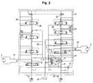
- FIG. 2 is a circuit diagram of a straight traveling hydraulic circuit according to an embodiment of the present invention.
- FIG. 3 is a sectional view of a control valve included in the straight traveling hydraulic circuit according to an embodiment of the present invention.
- FIG. 4 is a sectional view of the control valve taken along A-A line of FIG. 3 ;
- FIG. 5 is a sectional view of the control valve of FIG. 3 in a used state
- FIG. 6 is a detailed sectional view of an orifice part illustrated in FIG. 3 ;
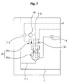
- FIG. 7 is a view illustrating main parts of the straight traveling hydraulic circuit according to an embodiment of the present invention.
- the straight traveling hydraulic circuit includes first and second variable hydraulic pumps 15 and 18 ; a left traveling motor 2 and a first working device such as an arm (not illustrated) and so on, connected to the first hydraulic pump 15 ; a plurality of switching valves 12 and 26 installed in a flow path 1 of the first hydraulic pump 15 , and shifted to control hydraulic fluid fed to the left traveling motor 2 and the first working device, respectively, in response to pilot signal pressures a 1 and b 1 being applied thereto; a right traveling motor 3 and a second working device such as a boom and so on, connected to the second hydraulic pump 18 ; a plurality of switching valves 11 and 28 installed in a flow path 9 of the second hydraulic pump 18 , and shifted to control the hydraulic fluid fed to the right traveling motor 3 and the second working device, respectively, in response to pilot signal pressures a 2 and b 2 being applied thereto; a straight traveling valve 4 installed in the flow path 9 of the second hydraulic pump 18 , and
- the control valve 31 includes a main valve 31 a composed of a poppet 47 having a flow path connected to a flow path on an inlet side of the traveling switching valve 11 and opening/closing the branch flow path, a piston 38 pressing the poppet 47 to block the branch flow path 7 - 1 when a signal pressure is applied from an outside, and an elastic member 46 (e.g., compression coil spring) elastically supported between the poppet 47 and the piston 38 and elastically biasing the pilot poppet 47 , which has been pressed to block the branch flow path 7 - 1 , to its initial state; and an auxiliary valve 31 b composed of a spool 42 shifted to supply the hydraulic fluid on the inlet side of the straight traveling valve 4 to the piston 38 as a signal pressure, in response to a pilot signal pressure a 4 being supplied thereto, and a valve spring 33 elastically biasing the spool 42 , which has intercepted the supply of the hydraulic fluid on the inlet side of the straight traveling valve 4 to the piston 38 as
- an elastic member 46
- the straight traveling hydraulic circuit according to an embodiment of the present invention further includes at least one orifice 47 a formed on a periphery of the poppet 47 of the main valve 31 a in the form of a step and serving as a damper when the branch flow path 7 - 1 is blocked by bringing the poppet 47 into contact with a seat ST.
- the straight traveling hydraulic circuit further includes a check valve 48 installed in a flow path branched from the flow path on the inlet side of the straight traveling valve 4 and supplying the signal pressure to the piston 38 of the main valve 31 a.
- the straight traveling hydraulic circuit according to an embodiment of the present invention further includes an orifice 6 installed in the branch flow path 7 - 1 between a flow path on the outlet side of the straight traveling valve 4 and the main valve 31 a.
- the left traveling motor 2 is driven by the hydraulic fluid fed from the first hydraulic pump 15
- the right traveling motor 3 is driven by the hydraulic fluid fed from the second hydraulic pump 18 .
- pilot signal pressure a 3 of about 40K that is applied to a straight traveling valve 4 an inner spool of the straight traveling valve 4 is shifted in the right direction as shown in the drawing.
- pilot signal pressure b 1 that is applied to a first working device switching valve 26
- an inner spool of the switching valve 26 is shifted in the left direction as shown in the drawing.
- signal pressure cl applied to a first center bypass valve 22
- an inner spool of the bypass valve 22 is shifted in the left direction, and thus a pressure is formed in a first center bypass flow path.
- a part of the hydraulic fluid fed from the first hydraulic pump 15 is supplied to the left traveling motor 2 via the flow path 1 , the switching valve 12 , and the flow path 14 .
- a part of the hydraulic fluid fed from the first hydraulic pump 15 is supplied to the right traveling motor 3 via a flow path 8 , the straight traveling valve 4 , the switching valve 11 , and the flow path 20 .
- the hydraulic fluid fed from the first hydraulic pump 15 is used to drive the left traveling motor 2 and the right traveling motor 3 .
- the hydraulic fluid fed from the second hydraulic pump 18 is supplied to the first working device switching valve 26 via the flow path 9 , the straight traveling valve 4 , and the flow path 32 , to drive the corresponding working devices such as the arm and so on.
- the hydraulic fluid fed from the second hydraulic pump 18 is supplied to the first working device switching valve 26 and is used to drive the corresponding devices.
- a part of the hydraulic fluid being fed from the second hydraulic pump 18 to the switching valve 26 is supplied to a flow path 7 via the flow path 32 , the straight traveling valve 4 , and the flow path 9 .
- the hydraulic fluid having been supplied to the flow path 7 passes in turn through a poppet 47 of a control valve 31 installed in the branch flow path 7 - 1 connecting the outlet of the straight traveling valve 4 to the flow path 7 , and an orifice 6 .
- the hydraulic fluid fed from the second hydraulic pump 18 is supplied to the branch flow path 7 - 1 through the flow path 7 , it pushes the poppet 47 as illustrated in FIG. 3 upward to open the branch flow path 7 - 1 .
- the hydraulic fluid in a flow path 7 - 2 that is branched from the flow path 7 is supplied to the flow path 7 - 3 through a check valve 48 as illustrated in FIG. 4 .
- the hydraulic fluid in the flow path 7 - 3 is intercepted by the spool 42 as illustrated in FIG. 3 .
- a part of the hydraulic fluid fed from the second hydraulic pump 18 is supplied to the right traveling motor 3 via the traveling switching valve 11 , and simultaneously, a part of the hydraulic fluid fed from the second hydraulic pump 18 is supplied to the left traveling motor 2 through a flow path 8 .
- the pilot signal pressure a 4 is applied to the auxiliary valve 31 b through a port 41 , and thus the inner spool 42 is shifted in the right direction as shown in FIG. 7 (whereas the spool 42 is shifted in the left direction in FIG. 5 ). Accordingly, the hydraulic fluid fed from the second hydraulic pump 18 is supplied to the flow path 7 through the control valve, the straight traveling valve 4 , and the flow path 9 in turn.
- the branch flow path 7 - 1 branched from the flow path 7 is blocked by the control valve 31 . That is, the hydraulic fluid in the second hydraulic pump 18 , having been supplied to the flow path 7 , is intercepted from being supplied to the left traveling motor 2 or the right traveling motor 3 by the control valve 31 .
- the hydraulic fluid fed from the first hydraulic pump 15 is supplied to the left traveling motor 2 and the right traveling motor 3 to drive the equipment, but the hydraulic fluid fed from the second hydraulic pump 18 is not supplied to the left traveling motor 2 or the right traveling motor 3 .
- control valve 31 will be described in detail.
- At least one orifice 47 a in the form of a step is formed on the periphery of the poppet 47 (in FIG. 6 , two orifices are illustrated). Accordingly, the poppet 47 is prevented from being damaged due to a shock given when the poppet becomes in contact with the seat ST by a strong pressure that is applied to the piston 38 .
- the pressure in the branch flow path 7 - 1 is increased up to the predetermined pressure of the main relief valve 10 by an orifice 47 a formed on the periphery of the poppet as illustrated in FIG. 6 (which corresponds to a gap between an inner diameter D of the seat ST and a second outer diameter D 2 of the poppet 47 , or a gap between the inner diameter D of the seat ST and a second outer diameter D 2 of the poppet 47 ).
- the orifice 47 a serves as a damper that forms a reaction force in the branch flow path 7 - 1 to counteract the pressure being applied during the descending of the poppet 47 .
- the traveling motor switching valves 12 and 11 are shifted in response to the pilot signal pressures a 1 and a 2 being applied thereto.
- the traveling side pilot signal pressure which is kept about 10 ⁇ 12K, shifts the switching valves 12 and 11 . Accordingly, in the case where the traveling motor switching valves 12 and 11 are half shifted, it is possible to control the flow of the hydraulic fluid by a P-N notch (that controls the hydraulic fluid fed from the hydraulic pump to the hydraulic tank), a P-C notch (that controls the hydraulic fluid fed from the hydraulic pump to the hydraulic cylinder), and a C-T notch (that controls the hydraulic fluid fed from the hydraulic cylinder to the hydraulic tank).
- the spool notches of the traveling motor switching valves 11 and 12 have the same structure, but due to the difference in accumulated tolerance and processing condition between the spools, it is difficult for the spool notches to keep the same cross-sectional area. However, even in the case where the spool notches have different cross-sectional areas, a declination of the equipment can be prevented from occurring by intercepting the supply of the hydraulic fluid from the second hydraulic pump 18 to the left traveling motor 2 or the right traveling motor 3 under the control of the control valve 31 .
- the straight traveling hydraulic circuit according to the present invention has the following advantages.
Landscapes
- Engineering & Computer Science (AREA)
- General Engineering & Computer Science (AREA)
- Mining & Mineral Resources (AREA)
- Civil Engineering (AREA)
- Structural Engineering (AREA)
- Physics & Mathematics (AREA)
- Fluid Mechanics (AREA)
- Mechanical Engineering (AREA)
- Automation & Control Theory (AREA)
- Chemical & Material Sciences (AREA)
- Combustion & Propulsion (AREA)
- Transportation (AREA)
- Fluid-Pressure Circuits (AREA)
- Operation Control Of Excavators (AREA)
- Control Of Fluid Gearings (AREA)
- Motor Power Transmission Devices (AREA)
Applications Claiming Priority (2)
| Application Number | Priority Date | Filing Date | Title |
|---|---|---|---|
| KR10-2006-0082262 | 2006-08-29 | ||
| KR1020060082262A KR100753990B1 (ko) | 2006-08-29 | 2006-08-29 | 주행직진용 유압회로 |
Publications (2)
| Publication Number | Publication Date |
|---|---|
| US20080053082A1 US20080053082A1 (en) | 2008-03-06 |
| US7581392B2 true US7581392B2 (en) | 2009-09-01 |
Family
ID=38615932
Family Applications (1)
| Application Number | Title | Priority Date | Filing Date |
|---|---|---|---|
| US11/821,108 Active 2028-03-14 US7581392B2 (en) | 2006-08-29 | 2007-06-21 | Straight traveling hydraulic circuit |
Country Status (5)
| Country | Link |
|---|---|
| US (1) | US7581392B2 (fr) |
| EP (1) | EP1895060B1 (fr) |
| JP (1) | JP5113449B2 (fr) |
| KR (1) | KR100753990B1 (fr) |
| CN (1) | CN101135325B (fr) |
Cited By (6)
| Publication number | Priority date | Publication date | Assignee | Title |
|---|---|---|---|---|
| EP2466017A1 (fr) | 2010-12-14 | 2012-06-20 | Caterpillar, Inc. | Circuit de commande à boucle fermée avec assistance de pompe à circuit ouvert pour déplacement à haute vitesse |
| WO2012107186A1 (fr) | 2011-02-07 | 2012-08-16 | Caterpillar Inc. | Système hydrostatique configuré pour être intégré dans une excavatrice |
| US20140345268A1 (en) * | 2011-12-15 | 2014-11-27 | Volvo Construction Equipment Ab | Travel control system for construction machinery |
| US20160002888A1 (en) * | 2013-02-15 | 2016-01-07 | Parker-Hannifin Corporation | Variable load sense open center hybrid system |
| US20160160883A1 (en) * | 2013-07-24 | 2016-06-09 | Volvo Construction Equipment Ab | Hydraulic circuit for construction machine |
| US20160201297A1 (en) * | 2013-08-13 | 2016-07-14 | Volvo Construction Equipment Ab | Flow control valve for construction equipment |
Families Citing this family (15)
| Publication number | Priority date | Publication date | Assignee | Title |
|---|---|---|---|---|
| KR20100012008A (ko) * | 2008-07-26 | 2010-02-04 | 볼보 컨스트럭션 이키프먼트 홀딩 스웨덴 에이비 | 선회 속도 조정시스템이 구비된 파이프 레이어 |
| JP2011075025A (ja) * | 2009-09-30 | 2011-04-14 | Kyb Co Ltd | 走行直進制御装置 |
| CN103339387B (zh) * | 2010-12-27 | 2015-11-25 | 沃尔沃建造设备有限公司 | 用于施工机械的液压泵 |
| WO2012125794A1 (fr) * | 2011-03-15 | 2012-09-20 | Husco International, Inc. | Système permettant de distribuer le fluide à partir de multiples pompes vers une pluralité de fonctions hydrauliques en fonction de la priorité |
| CN103597218B (zh) * | 2011-06-09 | 2016-04-06 | 沃尔沃建造设备有限公司 | 用于工程机械的液压系统 |
| CN103062140B (zh) | 2013-01-17 | 2014-01-08 | 江苏恒立高压油缸股份有限公司 | 基于合流控制方式的液压装置 |
| DE112013006604T5 (de) * | 2013-02-06 | 2016-01-21 | Volvo Construction Equipment Ab | Hydraulikbaumaschine |
| WO2015137329A1 (fr) | 2014-03-11 | 2015-09-17 | 住友重機械工業株式会社 | Pelle |
| CN106232905B (zh) * | 2014-04-15 | 2018-10-12 | 沃尔沃建造设备有限公司 | 用于工程设备的行驶控制装置及其控制方法 |
| CN107075832B (zh) * | 2014-11-05 | 2020-05-26 | 沃尔沃建筑设备公司 | 用于工程机械的直线行驶设备及其控制方法 |
| JP6723896B2 (ja) * | 2016-10-25 | 2020-07-15 | 株式会社竹内製作所 | 油圧式走行装置 |
| FR3090787B1 (fr) * | 2018-12-20 | 2021-01-08 | Poclain Hydraulics Ind | Système de gestion de cylindrée pour tête d’ébranchage |
| KR102080086B1 (ko) * | 2019-12-31 | 2020-02-24 | 대호 (주) | 동시 작동이 가능한 트랙터 유압장치 |
| CN112482482B (zh) * | 2020-12-28 | 2022-04-12 | 雷沃工程机械集团有限公司 | 一种挖掘机 |
| CN113529844B (zh) * | 2021-07-08 | 2022-11-11 | 柳州柳工挖掘机有限公司 | 负流量挖掘机直行控制系统和方法 |
Citations (5)
| Publication number | Priority date | Publication date | Assignee | Title |
|---|---|---|---|---|
| US5692377A (en) * | 1995-01-11 | 1997-12-02 | Shin Caterpillar Mitsubishi Ltd. | Apparatus for controlling lifting operation |
| US6430922B2 (en) * | 2000-04-13 | 2002-08-13 | Kobelco Construction Machinery Co., Ltd. | Construction machine |
| US6708490B2 (en) * | 2001-08-22 | 2004-03-23 | Kobelco Construction Machinery Co., Ltd. | Hydraulic system for construction machine |
| US7178333B2 (en) * | 2004-03-18 | 2007-02-20 | Kobelco Construction Machinery Co., Ltd. | Hydraulic control system for hydraulic excavator |
| US7412827B2 (en) * | 2005-09-30 | 2008-08-19 | Caterpillar Inc. | Multi-pump control system and method |
Family Cites Families (7)
| Publication number | Priority date | Publication date | Assignee | Title |
|---|---|---|---|---|
| JP2766371B2 (ja) * | 1990-04-03 | 1998-06-18 | 住友建機株式会社 | 油圧ショベルの油圧回路 |
| JPH083194B2 (ja) * | 1992-04-03 | 1996-01-17 | カヤバ工業株式会社 | 建設車両の油圧回路 |
| KR0136987Y1 (ko) * | 1994-07-29 | 1999-04-01 | 추호석 | 평탄작업시 주행직진 회로 |
| KR100226279B1 (ko) * | 1997-06-25 | 1999-10-15 | 토니헬샴 | 주행직진용 유압회로 |
| KR200166282Y1 (ko) * | 1997-11-06 | 2000-01-15 | 토니헬 | 중장비용 유압 회로 |
| KR200183057Y1 (ko) * | 1998-05-25 | 2000-07-01 | 토니헬 | 중장비차량의 주행장치를 위한 유압시스템 |
| JP2004100847A (ja) * | 2002-09-10 | 2004-04-02 | Sumitomo (Shi) Construction Machinery Manufacturing Co Ltd | 建設機械の油圧回路 |
-
2006
- 2006-08-29 KR KR1020060082262A patent/KR100753990B1/ko not_active Expired - Fee Related
-
2007
- 2007-06-21 US US11/821,108 patent/US7581392B2/en active Active
- 2007-06-29 EP EP07012748.5A patent/EP1895060B1/fr not_active Ceased
- 2007-07-13 CN CN2007101366049A patent/CN101135325B/zh not_active Expired - Fee Related
- 2007-08-20 JP JP2007213541A patent/JP5113449B2/ja not_active Expired - Fee Related
Patent Citations (5)
| Publication number | Priority date | Publication date | Assignee | Title |
|---|---|---|---|---|
| US5692377A (en) * | 1995-01-11 | 1997-12-02 | Shin Caterpillar Mitsubishi Ltd. | Apparatus for controlling lifting operation |
| US6430922B2 (en) * | 2000-04-13 | 2002-08-13 | Kobelco Construction Machinery Co., Ltd. | Construction machine |
| US6708490B2 (en) * | 2001-08-22 | 2004-03-23 | Kobelco Construction Machinery Co., Ltd. | Hydraulic system for construction machine |
| US7178333B2 (en) * | 2004-03-18 | 2007-02-20 | Kobelco Construction Machinery Co., Ltd. | Hydraulic control system for hydraulic excavator |
| US7412827B2 (en) * | 2005-09-30 | 2008-08-19 | Caterpillar Inc. | Multi-pump control system and method |
Cited By (9)
| Publication number | Priority date | Publication date | Assignee | Title |
|---|---|---|---|---|
| EP2466017A1 (fr) | 2010-12-14 | 2012-06-20 | Caterpillar, Inc. | Circuit de commande à boucle fermée avec assistance de pompe à circuit ouvert pour déplacement à haute vitesse |
| WO2012079745A1 (fr) | 2010-12-14 | 2012-06-21 | Caterpillar Inc. | Circuit d'attaque en boucle fermée avec assistance de pompe en circuit ouvert pour déplacement à grande vitesse |
| WO2012107186A1 (fr) | 2011-02-07 | 2012-08-16 | Caterpillar Inc. | Système hydrostatique configuré pour être intégré dans une excavatrice |
| US20140345268A1 (en) * | 2011-12-15 | 2014-11-27 | Volvo Construction Equipment Ab | Travel control system for construction machinery |
| US20160002888A1 (en) * | 2013-02-15 | 2016-01-07 | Parker-Hannifin Corporation | Variable load sense open center hybrid system |
| US9777464B2 (en) * | 2013-02-15 | 2017-10-03 | Parker-Hannifin Corporation | Variable load sense open center hybrid system |
| US20160160883A1 (en) * | 2013-07-24 | 2016-06-09 | Volvo Construction Equipment Ab | Hydraulic circuit for construction machine |
| US10184499B2 (en) * | 2013-07-24 | 2019-01-22 | Volvo Construction Equipment Ab | Hydraulic circuit for construction machine |
| US20160201297A1 (en) * | 2013-08-13 | 2016-07-14 | Volvo Construction Equipment Ab | Flow control valve for construction equipment |
Also Published As
| Publication number | Publication date |
|---|---|
| JP2008057778A (ja) | 2008-03-13 |
| EP1895060A2 (fr) | 2008-03-05 |
| KR100753990B1 (ko) | 2007-08-31 |
| US20080053082A1 (en) | 2008-03-06 |
| EP1895060A3 (fr) | 2015-08-05 |
| EP1895060B1 (fr) | 2017-01-25 |
| CN101135325B (zh) | 2012-07-04 |
| JP5113449B2 (ja) | 2013-01-09 |
| CN101135325A (zh) | 2008-03-05 |
Similar Documents
| Publication | Publication Date | Title |
|---|---|---|
| US7581392B2 (en) | Straight traveling hydraulic circuit | |
| US7614225B2 (en) | Straight traveling hydraulic circuit | |
| US8146482B2 (en) | Hydraulic circuit having holding valve of external pilot pressure operation type | |
| US9103355B2 (en) | Flow control valve for construction machine | |
| US9249812B2 (en) | Hydraulic circuit for pipe layer | |
| US7987764B2 (en) | Flow control apparatus for heavy construction equipment | |
| US9261114B2 (en) | Hydraulic pressure-regulating valve for construction equipment | |
| US8113233B2 (en) | Hydraulic circuit of option device for excavator | |
| US9085875B2 (en) | Hydraulic control valve for construction machinery | |
| US20150330416A1 (en) | Fluid pressure control device for power shovel | |
| WO1993024757A1 (fr) | Systeme de commande hydraulique | |
| EP0709579B1 (fr) | Appareil pour la marche en ligne droite pour engins de construction lourds | |
| EP0967398A1 (fr) | Soupapes de regulation de pression | |
| US20140345268A1 (en) | Travel control system for construction machinery | |
| JP6822930B2 (ja) | 流量制御弁 | |
| KR100226281B1 (ko) | 가변우선장치 | |
| JP4033849B2 (ja) | 可変容量型油圧ポンプ制御装置 | |
| US7017470B2 (en) | Flow control apparatus for construction heavy equipment | |
| US9702380B2 (en) | Fluid pressure control device for power shovel | |
| EP2833002B1 (fr) | Dispositif vanne de régulation pour pelle mécanique | |
| JP4090429B2 (ja) | 油圧制御回路 | |
| JP6510910B2 (ja) | 油圧駆動装置 | |
| KR101486988B1 (ko) | 소형급 건설중장비의 네거티브 유량조절 시스템 | |
| JP3662623B2 (ja) | ロードセンシング回路 | |
| JP2005076237A (ja) | 油圧制御装置 |
Legal Events
| Date | Code | Title | Description |
|---|---|---|---|
| AS | Assignment |
Owner name: VOLVO CONSTRUCTION EQUIPMENT HOLDING SWEDEN AB, SW Free format text: ASSIGNMENT OF ASSIGNORS INTEREST;ASSIGNOR:JEON, MAN SUK;REEL/FRAME:019512/0524 Effective date: 20070525 |
|
| STCF | Information on status: patent grant |
Free format text: PATENTED CASE |
|
| FEPP | Fee payment procedure |
Free format text: PAYOR NUMBER ASSIGNED (ORIGINAL EVENT CODE: ASPN); ENTITY STATUS OF PATENT OWNER: LARGE ENTITY |
|
| FEPP | Fee payment procedure |
Free format text: PAYOR NUMBER ASSIGNED (ORIGINAL EVENT CODE: ASPN); ENTITY STATUS OF PATENT OWNER: LARGE ENTITY Free format text: PAYER NUMBER DE-ASSIGNED (ORIGINAL EVENT CODE: RMPN); ENTITY STATUS OF PATENT OWNER: LARGE ENTITY |
|
| FPAY | Fee payment |
Year of fee payment: 4 |
|
| FPAY | Fee payment |
Year of fee payment: 8 |
|
| MAFP | Maintenance fee payment |
Free format text: PAYMENT OF MAINTENANCE FEE, 12TH YEAR, LARGE ENTITY (ORIGINAL EVENT CODE: M1553); ENTITY STATUS OF PATENT OWNER: LARGE ENTITY Year of fee payment: 12 |