US7591329B2 - Auger with a movable gouge for making a borehole - Google Patents
Auger with a movable gouge for making a borehole Download PDFInfo
- Publication number
- US7591329B2 US7591329B2 US11/493,706 US49370606A US7591329B2 US 7591329 B2 US7591329 B2 US 7591329B2 US 49370606 A US49370606 A US 49370606A US 7591329 B2 US7591329 B2 US 7591329B2
- Authority
- US
- United States
- Prior art keywords
- core
- auger
- gouge
- movable
- translation
- Prior art date
- Legal status (The legal status is an assumption and is not a legal conclusion. Google has not performed a legal analysis and makes no representation as to the accuracy of the status listed.)
- Active, expires
Links
Images


Classifications
-
- E—FIXED CONSTRUCTIONS
- E21—EARTH OR ROCK DRILLING; MINING
- E21B—EARTH OR ROCK DRILLING; OBTAINING OIL, GAS, WATER, SOLUBLE OR MELTABLE MATERIALS OR A SLURRY OF MINERALS FROM WELLS
- E21B10/00—Drill bits
- E21B10/44—Bits with helical conveying portion, e.g. screw type bits; Augers with leading portion or with detachable parts
-
- E—FIXED CONSTRUCTIONS
- E02—HYDRAULIC ENGINEERING; FOUNDATIONS; SOIL SHIFTING
- E02D—FOUNDATIONS; EXCAVATIONS; EMBANKMENTS; UNDERGROUND OR UNDERWATER STRUCTURES
- E02D5/00—Bulkheads, piles, or other structural elements specially adapted to foundation engineering
- E02D5/22—Piles
- E02D5/34—Concrete or concrete-like piles cast in position ; Apparatus for making same
- E02D5/38—Concrete or concrete-like piles cast in position ; Apparatus for making same making by use of mould-pipes or other moulds
- E02D5/385—Concrete or concrete-like piles cast in position ; Apparatus for making same making by use of mould-pipes or other moulds with removal of the outer mould-pipes
Definitions
- a tool such as an auger that serves to dig a cylindrical excavation in the ground corresponding to the dimensions of the pile that is to be made, and that also serves to raise the excavated material.
- the auger is fitted with a dip tube that is mounted to slide in the hollow core of the auger and that serves, while the auger is being raised, to inject progressively into the borehole the concrete or grout that is to form the pile.
- the forces that can be absorbed by a bored or cast-in-place pile depend firstly on its diameter and secondly on the coefficient of friction that exists between the outer wall of the pile and the inside wall of the borehole.
- FIG. 1 This is shown in accompanying FIG. 1 , where reference 10 designates the cylindrical borehole, reference 12 the inside wall of the borehole, and reference 14 the helical groove formed in the wall 12 of the borehole.
- reference 10 designates the cylindrical borehole
- reference 12 the inside wall of the borehole
- reference 14 the helical groove formed in the wall 12 of the borehole.
- pile 16 with its helical rib 18 penetrating into the ground S.
- An object of the present invention is to provide an auger fitted with a movable gouge in which it can be ensured that the gouge is extended effectively while the auger is rising in a manner that is reliable with the gouge being maintained in this position.
- the auger comprises:
- the movable gouge is moved from its retracted position to its active or extended position by the additional member moving in translation or rotation.
- the gouge is extended into its active position in a manner that is very reliable.
- said additional member is a tubular element extending over the entire length of the core of the auger and having a top end connected to a pipe for feeding a slurry under pressure and whose bottom end is provided with at least one orifice for enabling the slurry to be injected into the borehole.
- said tubular element is movable in translation in said core, and said control means cause the gouge to be displaced from its retracted position to its active position in response to the movement in translation of said tubular element.
- said tubular element is movable in rotation in said core, and said control means cause the gouge to be displaced from its retraced position to its active position in response to said tubular element turning.
- said tubular element is a dip tube which is movable in translation in said hollow core between a retracted position in which the bottom end of the dip tube closes the bottom end of the core of the auger, and an extended position in which the bottom end of the dip tube projects from the bottom end of the auger.
- said additional member is a tube segment mounted to be movable in translation and/or in rotation in the hollow core of the auger, at its bottom end.
- said tube segment is mounted to move in translation inside the core of the auger, and said control means cause the gouge to be displaced from its retracted position to its active position in response to the displacement of the tube segment.
- said tube segment is movable in rotation inside the core of the auger, and said control means cause the gouge to be displaced from its retracted position to its active position in response to the movement in rotation of said tube portion.
- the core of said auger comprises a top portion and a bottom portion that is movable in translation relative to said top portion over a predetermined length, said gouge being mounted on said bottom portion, said additional member comprises a tubular part secured to the bottom end of the top portion of said core and penetrating inside said bottom portion of the hollow core, and said control means are mounted on said tubular part in such a manner that displacement of said bottom portion of the core in translation relative to said tubular part causes the gouge to be displaced from its retracted position to its active position.
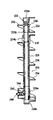
- FIG. 1 is a vertical section through a bored pile obtained using an auger with a gouge
- FIG. 2 is an elevation view of a boring machine assembly including an auger with a movable gouge
- FIGS. 3A and 3B show the bottom end of an auger fitted with a dip tube corresponding to a first embodiment of the invention
- FIG. 4 is a view from beneath showing the bottom end of the core of the auger in the first embodiment of the invention
- FIG. 5 shows the control circuit for controlling the movable gouge in the first embodiment of the invention
- FIG. 6 shows the bottom end of the auger in a second embodiment of the invention
- FIG. 7 is a simplified plan view of the FIG. 6 auger
- FIGS. 8A and 8B are section views on line XI-XI of FIG. 6 showing the gouge in its “extended” position and in its “retracted” position;
- FIG. 9 is a vertical section view of the bottom end of the auger in a variant of the first embodiment of the invention.
- FIGS. 10A and 10B are fragmentary perspective views of the bottom portion of the FIG. 9 auger showing the movable gouge in its two positions;
- FIGS. 11A and 11B show the bottom end of the auger in a third embodiment of the invention.
- FIG. 12 shows the bottom end of the auger in a fourth embodiment of the invention.
- FIG. 13 is an elevation view of a fifth embodiment of the invention.
- FIG. 14 is a side view of the fifth embodiment of the invention.
- FIG. 15 is a vertical section view of the fifth embodiment of the invention.
- FIG. 16 is an elevation view of the top portion of the cutter head in the retracted position in a fifth embodiment of the invention.
- FIG. 17 is a vertical section view on line A-A of FIG. 16 ;
- FIG. 18 is a horizontal section view on line B-B of FIG. 16 ;
- FIG. 19 is a view similar to that of FIG. 16 , the cutter head being in its extended position;
- FIG. 20 is a vertical section view on line C-C of FIG. 19 ;
- FIG. 21 is a perspective view of the bottom portion of the cutter head
- FIG. 22 is a view analogous to FIG. 21 , but partially cut away.
- FIG. 23 is a vertical section view of the bottom end of the cutter head.
- FIG. 2 there follows a description of the boring machine assembly including the gouge-carrying auger.
- a carriage 26 can move along the guide mast 22 , the carriage carrying a drive head 28 for setting the auger 30 into rotation.
- the carriage 26 can be moved along the mast 22 by means that are not shown. It is thus possible to control both the speed of rotation of the auger using the rotary drive head 28 and also to control the linear displacement speed of the auger by controlling the displacement of the carriage 26 relative the mast 22 .
- the auger 30 is constituted by a hollow cylindrical core 32 and by two helical blades or “flights” 34 and 36 that are angularly offset by 180°.
- the core 32 is terminated by a pointed tip 35 .
- the leading edges 34 a and 36 a of the flights are fitted with teeth such as 38 .
- the auger would not go beyond the invention for the auger to have a single helical flight or for the auger to have one helical flight extending along its entire height and a second helical flight extending over its end portion close to its tip 35 .
- the additional member is a tubular part that extends over the entire length of the core of the auger, and that is preferably a dip tube.
- Dip-tube-fitted augers are boring machines that are well known and that are described in particular in French patent application No. 2 807 455 in the name of the Applicant, which should be considered as forming an integral portion of the present description.
- the auger has a hollow core in which a “dip” tube can move in translation, the top end of the dip tube being connected by a hose to a source of grout or cement or more generally a slurry, and the bottom end can project from the bottom end of the auger to allow the grout or the concrete to be injected through orifices into the borehole made using the auger.
- the dip tube can be moved in translation relative to the auger, e.g. with the help of actuators mounted on the rotary drive head of the auger, and as a general rule the dip tube can also be moved in rotation about its longitudinal axis relative to the auger.
- the drive means of the movable gouge are controlled by the dip tube moving in translation relative to the auger.
- FIGS. 3A and 3B shows the bottom portion of the auger 30 with its core 32 , its flights 34 and 36 , and its pivotally-mounted gouge 42 .
- a dip tube 100 is slidably mounted in the hollow core 32 and the bottom end of the dip tube is closed by a conically-shaped tip 102 .
- the dip tube has a plurality of orifices 104 to allow the grout or the cement to escape.
- the bottom face 32 a of the core 32 of the auger is provided with notches such as 106 suitable for co-operating with studs 108 provided at the periphery of the bottom end of the dip tube, i.e. immediately above its end 102 .
- the auger and the dip tube are constrained to rotate together.
- the bottom end of the dip tube 100 occupies a position such that the orifices 104 are disengaged, and naturally the studs 108 are moved out from the notches 106 .
- moving pistons such as 110 are mounted in the notches 106 .
- the end 32 a of the core of the auger may have four notches 106 , each notch having two moving pistons 110 mounted therein.
- each piston 110 is constituted by a rod 112 suitable for receiving drive from the studs 108 via a first end 112 , while its second end 112 b co-operates with a return spring 114 .
- the rod 112 is associated with a piston 116 mounted to move in a cylindrical enclosure 118 filled with an incompressible liquid.
- the piston 116 subdivides the cylinder 118 into two respective chambers 120 and 122 .
- Each chamber is connected by a duct 124 , 126 to a respective control actuator 128 , 130 .
- the control actuators 128 and 130 act on the opposite sides of a pivot axis 44 of the gouge 42 so as to bring said gouge respectively into its extended position or into its retracted position.
- FIGS. 6 , 7 , and 8 show a second embodiment of the invention.
- use is made of rotary movement of the dip tube relative to the auger for the purpose of controlling the movable gouge drive means.
- an additional motor 140 is provided, that enables rotary drive to be imparted to the dip tube 100 relative to the core 32 of the auger. More precisely, this capacity for rotation is limited by two abutments 142 and 144 formed at the top end of the core 32 of the auger and by an extension 146 secured to the outside face at the top end 100 a of the dip tube.
- the dip tube 100 can be brought into a first position in which the extension 146 is in contact with the abutment 142 , or into a second position in which the extension 146 is in contact with the second abutment 144 .
- the dip tube 100 has a portion 150 set back from its outside wall 100 b , which portion is also visible in FIGS. 8A and 8B .
- This set-back portion 150 constitutes a cam that can be turned about the longitudinal axis X-X′ of the dip tube and of the core 32 of the auger.
- Two pushers 152 and 154 are mounted level with the movable gouge 42 , the pushers being movable in translation in holes 156 and 158 formed through the core 32 of the auger.
- the first ends of the pushers are in contact with the outside face of the dip tube 100 while their other ends are in contact with the control portion of the movable gouge on either side of its pivot axis 44 .
- the pusher 152 In the first angular position of the dip tube 100 , the pusher 152 is in contact with the outside wall 100 b of the dip tube, while the pusher 154 is in contact with the setback 150 , thus bringing the movable gouge 42 into the extended position ( FIG. 8A ). In contrast, in the second angular position, it is the first pusher 152 that is in contact with the setback 150 , while the second pusher 154 is in contact with the outside wall 100 b of the dip tube 100 . This holds the gouge 42 in its retracted position.
- FIGS. 9 , 10 A, and 10 B there follows a description of a variant of the first embodiment of the invention.
- the control member is constituted essentially by a ring 160 with teeth occupying part of its circumference.
- the ring surrounds the tip tube 100 is and is free to rotate relative thereto, but is prevented from moving in vertical translation relative to the dip tube.
- the ring 160 is secured to a control finger 162 which penetrates into a helical slot 164 formed in the corresponding portion of the dip tube and constituting a cam.
- the helical slot formed in the dip tube is preceded by a vertical slot which therefore has no effect on the ring.
- the toothed portion of the rotary ring 162 co-operates with a control portion 42 a of the movable groove 42 , which control portion is likewise toothed.
- the meshing between the toothed portion of the ring 162 and the control portion 42 a of the gouge 42 takes place through a slot 166 formed in the bottom portion of the hollow core 32 of the auger.
- the helical slot 164 acts as a cam causing the control finger 162 to turn in one direction or the other and thus turning the partially-toothed ring 162 .
- the ring drives the movable gouge 42 to turn about its own axis 42 so as to bring it either into the retraced position as shown in FIG. 10A or into the extended position as shown in FIG. 10B .
- a rotation sensor can be mounted on the pivot axis 44 of the gouge 42 .
- the signal delivered by the sensor is conveyed to the control assembly of the auger and serves to verify that the gouge 42 does indeed occupy the desired position.
- FIGS. 11A and 11B there follows a description of a third embodiment of the invention. It corresponds to the auger 30 not being fitted with a tubular element extending along the entire length of the core of the auger. The grout or concrete is then injected into the borehole by feeding the hollow core 32 of the auger therewith.
- the bottom end of the auger is fitted with a movable part 170 constituted by a segment of tube 172 of length that is short relative to the length of the auger and closed at its bottom end by an end wall 174 of conical shape forming the pointed tip of the auger.
- the tube segment 172 is free to move in translation in the hollow core of the auger and is provided with orifices 176 through which the grout or concrete exits.
- the movable part 170 is in the retracted position inside the auger, the movable part is constrained to rotate together therewith by studs 178 and notches 180 formed in the bottom edge of the core 32 of the auger.
- the movable part 170 During downward movement of the auger, corresponding to digging the borehole, the movable part 170 is held retracted inside the core of the auger ( FIG. 11A ).
- the pressure of the material on the movable part 170 and also the action of the surrounding ground causes the movable part 170 to move in translation relative to the core of the auger, with the amplitude of this relative movement being limited, for example, by abutments (not shown in the figures). This is shown in FIG. 11B .
- This result can also be obtained by interposing a spring between the core of the auger and the movable part. While the auger is moving downwards, the spring is compressed. When the upward movement is started, the spring can expand and cause the movable part to be extended.
- This relative movement in translation serves to control the pivoting of the gouge 42 via drive means that are represented symbolically by reference 181 .
- the control means may be of the type shown in FIGS. 6 to 8 (hydraulic) or of the type shown in FIGS. 9 and 10 (mechanical), with the tube segment 172 of the movable part replacing the dip tube.
- FIG. 12 shows a fourth embodiment of the invention.
- the auger 30 is fitted with a movable part 170 that is mounted to slide in the hollow 32 of the auger.
- the difference relative to the third embodiment consists in the fact that the outside face of the tube portion 172 and the bottom end of the inside face of the hollow core 32 of the auger has complementary portions in relief 182 suitable for converting the movement in translation of the movable part 170 relative to the core of the auger when the auger rises, into a movement in rotation. It is this movement that is used to control the displacement of the gouge 42 .
- control means represented by reference 184 may then be of the type shown in FIGS. 6 and 8 , with the tube segment 172 replacing the dip tube.
- the movable gouge is caused to turn in order to go from its retracted position to its extended or active position. It will nevertheless be understood that by making modifications within the competence of the person skilled in the art, the control means could be arranged so that the movable gouge is caused to move in translation in a direction that is radial relative to the axis of the core of the auger.
- the auger is constituted by a cutter head 220 mounted at the bottom end of a string of hollow rods, these rods being provided with respective external helical blades or “flights”.
- the description below relates essentially to the cutter head 220 that serves to cause the gouge 240 to move.
- the gouge is moved in translation along a radial direction that is substantially orthogonal to the longitudinal axis of the cutter head 220 . Nevertheless, it will readily be understood that by a simple modification within the competence of the person skilled in the art, this movement could be a pivoting movement about an axis associated with the cutter head.
- the cutter head 220 comprises an top portion 222 and a bottom portion 224 .
- the top end 222 a of the cutter head is connected to a string of flight rods by connection means 226 .
- the bottom end 222 b of the top portion is extended downwards by a tubular extension 228 .
- the top portion 222 is constituted by a cylindrical body 230 and a flight 232 .
- the bottom portion 224 is generally in the form of a cylindrical hollow rod 234 provided with a flight 236 .
- the extension 228 of the bottom portion 222 is slidably mounted in the hollow rod 224 of the bottom portion 224 .
- connection means 238 constrain the portions 222 and 224 in rotation while allowing the portions 222 and 224 to perform relative movement in translation over a limited amplitude.
- the bottom end 224 a of the bottom portion 224 is provided with a movable gouge (or cutter tooth) 240 .
- the gouge 240 is connected to displacement means 242 for displacing the gouge.
- the bottom end 228 a of the tubular extension 228 is provided with control means 244 .
- the control means 244 co-operate with the displacement means 242 .
- the gouge 240 when the top portion 222 bears against the top end 224 b of the bottom portion, the gouge 240 is in its retracted position as shown in FIG. 13 . This corresponds to the auger moving downwards.
- the control means 244 act on the displacement means 242 to move the gouge 240 into its extended position and to hold it there. This corresponds to the auger being moved upwards.
- connection means 238 With reference below to FIGS. 16 to 20 , there follows a description of a preferred embodiment of the connection means 238 .
- the top end 234 a of the hollow rod 234 is secured to a hexagonal female connection box 246 .
- the bottom end 222 b of the top portion 222 is secured to the top portion 248 a of a hexagonal male drive member 248 .
- the bottom end 248 b of the male member 248 is secured to the top end 228 b of the extension 228 .
- the male and female members 246 are constrained to rotate together.
- the top end 246 a of the female member is provided with a retaining ring 250 secured to the female drive box 246 and projects out from the inside wall 246 c of the drive box 246 .
- the outer wall 248 c of the male member 248 is provided with a shoulder 252 that co-operates with the retaining ring 250 .
- the amplitude of the displacement is limited by co-operation between the ring 250 and the shoulder 252 .
- control and displacement means 242 , 244 there follows a description of a preferred embodiment of the control and displacement means 242 , 244 .
- a protected volume 254 is defined by the helix 256 of the flight, by a side wall 258 , and by a bottom plate 259 .
- a horizontal-axis guide tube 260 is secured to the rod 234 of the bottom portion 224 .
- the tube 260 extends radially.
- a piston 262 is mounted to slide in the tube.
- the gouge 240 is secured to a first end 262 a of the piston.
- the second end of the piston is in the form of an inclined surface 264 .
- the bottom end of the rod 234 is provided with a slot 266 in which a wedge-shaped control member 268 can move vertically.
- the wedge 268 is secured on the bottom end of the extension 228 .
- Vertical displacement of the extension 228 is converted into horizontal movement of the gouge 240 by co-operation between the surface 264 and the wedge 268 .
- a return system constituted by a lever 270 connected to the piston 262 and a return spring 272 causes the gouge 240 to be retracted.
- the top portion 222 bears against the bottom portion 224 .
- the extension 228 is in its low position in the rod 234 of the bottom portion 224 , and the wedge 268 does not act on the inclined surface 264 .
- the gouge 240 is held in its retracted position.
- the top and bottom portions 222 and 224 are spaced apart from each other.
- the wedge 268 occupies a high position and acts on the inclined surface 264 of the piston 262 .
- the gouge 240 is then taken to its extended position and it is held in this position so long as traction is exerted on the top portion 222 of the cutter head.
Landscapes
- Engineering & Computer Science (AREA)
- Structural Engineering (AREA)
- Life Sciences & Earth Sciences (AREA)
- Mining & Mineral Resources (AREA)
- General Life Sciences & Earth Sciences (AREA)
- Geology (AREA)
- Civil Engineering (AREA)
- General Engineering & Computer Science (AREA)
- Paleontology (AREA)
- Physics & Mathematics (AREA)
- Environmental & Geological Engineering (AREA)
- Fluid Mechanics (AREA)
- Mechanical Engineering (AREA)
- Geochemistry & Mineralogy (AREA)
- Earth Drilling (AREA)
- Organic Low-Molecular-Weight Compounds And Preparation Thereof (AREA)
- Transplanting Machines (AREA)
- Separation By Low-Temperature Treatments (AREA)
- Battery Electrode And Active Subsutance (AREA)
Applications Claiming Priority (4)
| Application Number | Priority Date | Filing Date | Title |
|---|---|---|---|
| FR0508057 | 2005-07-28 | ||
| FR0508057A FR2889241B1 (fr) | 2005-07-28 | 2005-07-28 | Tariere a ergot mobile |
| GB0607612.9 | 2006-04-18 | ||
| GB0607612A GB2440939B (en) | 2006-04-18 | 2006-04-18 | Cutting head provided with threading means |
Publications (2)
| Publication Number | Publication Date |
|---|---|
| US20070023207A1 US20070023207A1 (en) | 2007-02-01 |
| US7591329B2 true US7591329B2 (en) | 2009-09-22 |
Family
ID=37441280
Family Applications (1)
| Application Number | Title | Priority Date | Filing Date |
|---|---|---|---|
| US11/493,706 Active 2027-01-31 US7591329B2 (en) | 2005-07-28 | 2006-07-27 | Auger with a movable gouge for making a borehole |
Country Status (6)
| Country | Link |
|---|---|
| US (1) | US7591329B2 (de) |
| EP (1) | EP1748108B1 (de) |
| KR (1) | KR101355053B1 (de) |
| AT (1) | ATE480670T1 (de) |
| DE (1) | DE602006016690D1 (de) |
| PL (1) | PL1748108T3 (de) |
Cited By (7)
| Publication number | Priority date | Publication date | Assignee | Title |
|---|---|---|---|---|
| US20090294181A1 (en) * | 2008-05-29 | 2009-12-03 | Barbera James S | Box gusseted earth auger |
| US20090301779A1 (en) * | 2008-06-09 | 2009-12-10 | Thad Bick | Earth boring device |
| US20110259641A1 (en) * | 2008-09-08 | 2011-10-27 | Sinvent As | Apparatus and Method for Modifying the Sidewalls of a Borehole |
| US20140301791A1 (en) * | 2013-03-15 | 2014-10-09 | Edick Shahnazarian | Telescopic Foundation Screw Pile with Continuously Tapered Pile Body |
| US9523241B2 (en) | 2014-12-30 | 2016-12-20 | Halliburton Energy Services, Inc. | Multi shot activation system |
| US10161096B2 (en) * | 2016-05-31 | 2018-12-25 | Soletanche Freyssinet | Ground reinforcing device |
| WO2019204866A1 (en) * | 2018-04-25 | 2019-10-31 | Przemyslaw Adam Zakrzewski | Tool and method for forming piles |
Families Citing this family (12)
| Publication number | Priority date | Publication date | Assignee | Title |
|---|---|---|---|---|
| US8926228B2 (en) * | 2006-09-08 | 2015-01-06 | Ben Stroyer | Auger grouted displacement pile |
| IT1394001B1 (it) * | 2009-04-20 | 2012-05-17 | Soilmec Spa | Attrezzatura di scavo e costipazione per la costruzione di pali a vite. |
| IT1394002B1 (it) * | 2009-04-21 | 2012-05-17 | Soilmec Spa | Attrezzatura di scavo e costipazione per la costruzione di pali a vite. |
| US9995087B2 (en) * | 2012-01-19 | 2018-06-12 | Frankie A. R. Queen | Direct torque helical displacement well and hydrostatic liquid pressure relief device |
| US9366084B2 (en) * | 2012-01-19 | 2016-06-14 | Frankie A. R. Queen | Direct torque helical displacement well and hydrostatic liquid pressure relief device |
| GB2506235B (en) * | 2012-07-05 | 2017-07-05 | Arnold Tunget Bruce | Apparatus and method for cultivating a downhole surface |
| DE102012109333A1 (de) * | 2012-10-01 | 2014-04-03 | Götz Hudelmaier | Vorrichtung und Verfahren zum Ausbilden eines Hohlraums im Boden zum Herstellen einer im Boden eingelassenen Ortbetonstruktur |
| BE1021912B1 (nl) * | 2014-06-19 | 2016-01-26 | Jde Funderingstechniek Bvba | Boorvoorziening voor het vervaardigen van een funderingspaal |
| AT15492U1 (de) * | 2016-05-20 | 2017-10-15 | Dywidag-Systems Int Gmbh | Verfahren zum Schlag- oder Drehschlagbohren von Löchern sowie gleichzeitigem Profilieren von Bohrlochwänden in Erd-, Boden- oder Gesteinsmaterial |
| US20190234146A1 (en) * | 2016-10-11 | 2019-08-01 | Halliburton Energy Services, Inc. | Automatic bonding system for grounding mobile equipment |
| CN115822584A (zh) * | 2022-12-09 | 2023-03-21 | 郑州大学 | 道路检测用凿孔器 |
| FR3154738B1 (fr) * | 2023-10-27 | 2025-11-28 | Soletanche Freyssinet | Outil de coupe pour la fabrication d’un pieu fileté dans un sol |
Citations (9)
| Publication number | Priority date | Publication date | Assignee | Title |
|---|---|---|---|---|
| US4193462A (en) | 1977-03-02 | 1980-03-18 | Stahl- Und Apparatebau Hans Leffer Gmbh | Rotary boring head |
| GB2183703A (en) | 1985-08-22 | 1987-06-10 | Cementation Piling & Found | In situ concrete pile construction and under cutting tool |
| JPH01295913A (ja) | 1988-05-24 | 1989-11-29 | Tousen Asano Paul Kk | 大口径杭の拡大球根構築方法およびその装置 |
| WO1994002687A1 (en) | 1992-07-24 | 1994-02-03 | Wagstaff Piling Pty. Ltd. | Apparatus and method for forming piles |
| JPH06212873A (ja) * | 1992-11-25 | 1994-08-02 | Yookon Kk | 拡大掘削装置 |
| US5507357A (en) * | 1994-02-04 | 1996-04-16 | Foremost Industries, Inc. | Pilot bit for use in auger bit assembly |
| GB2316700A (en) | 1996-09-26 | 1998-03-04 | Kvaerner Cementation Found Ltd | Bearing capacity enhancement for piling applications |
| EP1471186A1 (de) | 2003-04-23 | 2004-10-27 | Compagnie Du Sol | Bohrschnecke zur Pfahlherstellung |
| EP1471187A1 (de) | 2003-04-22 | 2004-10-27 | Compagnie Du Sol | Gewindeschneideeinrichtung |
Family Cites Families (4)
| Publication number | Priority date | Publication date | Assignee | Title |
|---|---|---|---|---|
| US4565252A (en) * | 1984-03-08 | 1986-01-21 | Lor, Inc. | Borehole operating tool with fluid circulation through arms |
| JP3046194B2 (ja) * | 1994-02-09 | 2000-05-29 | 鹿島建設株式会社 | オーガビット |
| GB2377235A (en) * | 2001-07-17 | 2003-01-08 | Cie Du Sol | Drilling tool |
| US6991046B2 (en) * | 2003-11-03 | 2006-01-31 | Reedhycalog, L.P. | Expandable eccentric reamer and method of use in drilling |
-
2006
- 2006-07-24 EP EP06117715A patent/EP1748108B1/de active Active
- 2006-07-24 DE DE602006016690T patent/DE602006016690D1/de active Active
- 2006-07-24 PL PL06117715T patent/PL1748108T3/pl unknown
- 2006-07-24 AT AT06117715T patent/ATE480670T1/de not_active IP Right Cessation
- 2006-07-27 KR KR1020060070610A patent/KR101355053B1/ko not_active Expired - Fee Related
- 2006-07-27 US US11/493,706 patent/US7591329B2/en active Active
Patent Citations (9)
| Publication number | Priority date | Publication date | Assignee | Title |
|---|---|---|---|---|
| US4193462A (en) | 1977-03-02 | 1980-03-18 | Stahl- Und Apparatebau Hans Leffer Gmbh | Rotary boring head |
| GB2183703A (en) | 1985-08-22 | 1987-06-10 | Cementation Piling & Found | In situ concrete pile construction and under cutting tool |
| JPH01295913A (ja) | 1988-05-24 | 1989-11-29 | Tousen Asano Paul Kk | 大口径杭の拡大球根構築方法およびその装置 |
| WO1994002687A1 (en) | 1992-07-24 | 1994-02-03 | Wagstaff Piling Pty. Ltd. | Apparatus and method for forming piles |
| JPH06212873A (ja) * | 1992-11-25 | 1994-08-02 | Yookon Kk | 拡大掘削装置 |
| US5507357A (en) * | 1994-02-04 | 1996-04-16 | Foremost Industries, Inc. | Pilot bit for use in auger bit assembly |
| GB2316700A (en) | 1996-09-26 | 1998-03-04 | Kvaerner Cementation Found Ltd | Bearing capacity enhancement for piling applications |
| EP1471187A1 (de) | 2003-04-22 | 2004-10-27 | Compagnie Du Sol | Gewindeschneideeinrichtung |
| EP1471186A1 (de) | 2003-04-23 | 2004-10-27 | Compagnie Du Sol | Bohrschnecke zur Pfahlherstellung |
Non-Patent Citations (1)
| Title |
|---|
| Patent Abstracts of Japan, vol. 014, No. 81, Feb. 15, 1990 & JP 01 295913 a (Tousen Asano Paul KK; others, Nov. 29, 1989. |
Cited By (11)
| Publication number | Priority date | Publication date | Assignee | Title |
|---|---|---|---|---|
| US20090294181A1 (en) * | 2008-05-29 | 2009-12-03 | Barbera James S | Box gusseted earth auger |
| US7748479B2 (en) * | 2008-05-29 | 2010-07-06 | Barbera James S | Box gusseted earth auger |
| US20090301779A1 (en) * | 2008-06-09 | 2009-12-10 | Thad Bick | Earth boring device |
| US8196681B2 (en) * | 2008-06-09 | 2012-06-12 | Thad Bick | Earth boring device |
| US20110259641A1 (en) * | 2008-09-08 | 2011-10-27 | Sinvent As | Apparatus and Method for Modifying the Sidewalls of a Borehole |
| US9341026B2 (en) * | 2008-09-08 | 2016-05-17 | Sinvent As | Apparatus and method for modifying the sidewalls of a borehole |
| US20140301791A1 (en) * | 2013-03-15 | 2014-10-09 | Edick Shahnazarian | Telescopic Foundation Screw Pile with Continuously Tapered Pile Body |
| US9523241B2 (en) | 2014-12-30 | 2016-12-20 | Halliburton Energy Services, Inc. | Multi shot activation system |
| US10161096B2 (en) * | 2016-05-31 | 2018-12-25 | Soletanche Freyssinet | Ground reinforcing device |
| WO2019204866A1 (en) * | 2018-04-25 | 2019-10-31 | Przemyslaw Adam Zakrzewski | Tool and method for forming piles |
| US11441285B2 (en) | 2018-04-25 | 2022-09-13 | Ppx Technology Pty Ltd | Tool and method for forming piles |
Also Published As
| Publication number | Publication date |
|---|---|
| PL1748108T3 (pl) | 2011-03-31 |
| ATE480670T1 (de) | 2010-09-15 |
| US20070023207A1 (en) | 2007-02-01 |
| KR20070015015A (ko) | 2007-02-01 |
| EP1748108B1 (de) | 2010-09-08 |
| DE602006016690D1 (de) | 2010-10-21 |
| KR101355053B1 (ko) | 2014-01-24 |
| EP1748108A1 (de) | 2007-01-31 |
Similar Documents
| Publication | Publication Date | Title |
|---|---|---|
| US20070023207A1 (en) | Auger with a movable gouge for making a boreholes | |
| US6478512B2 (en) | Machine for making bored piles | |
| EP3953529B1 (de) | Konstruktionsverfahren und vorrichtung zur ausführung eines ortsgegossenen pfahls mit mehreren, in der tiefe kleiner werdenden durchmessern | |
| US3604214A (en) | Means and method of making columnar structures in situ | |
| US4911581A (en) | Pre-cast concrete pile and method and apparatus for its introduction into the ground | |
| US3864923A (en) | Impacted casing method for installing anchor piles or tiebacks in situ | |
| GB954842A (en) | Method and apparatus for forming piles in the earth | |
| JP2007291850A (ja) | 地中施工杭を作るための掘削装置および方法 | |
| US20150128458A1 (en) | Device for digging diaphragms | |
| EP2685006B1 (de) | Schneidkopf mit einfahrbarem, durch ein Zahnstangensystem betätigtem Gewindeschneidzahn | |
| US11085284B2 (en) | Vertical drilling system of auger type provided with a trajectory correcting device | |
| EP1277887B1 (de) | Verdrängerbohrer und Gerät, welches den Bohrer benutzt | |
| CN104404951A (zh) | 带扩径装置的长螺旋桩机及成桩方法 | |
| US4100750A (en) | Method for the production of piles cast in the ground and hollow auger for implementing the method | |
| KR860000450A (ko) | 땅속에서 콘크리이트 파일을 제조하는 장치 및 방법과 그 파일 | |
| US3568452A (en) | Method and apparatus for forming bulbular base piles | |
| CN102105638A (zh) | 利用机械混合和注入胶结液来固结土壤的设备 | |
| RU2426835C1 (ru) | Устройство для образования буронабивных свай | |
| CN1076980A (zh) | 灌注混凝土螺旋钻机 | |
| JP2009144469A (ja) | 掘削翼拡縮装置 | |
| US4436167A (en) | Method of excavating a pile hole and an apparatus therefor | |
| JP7281845B1 (ja) | 既存杭の切断装置 | |
| CN108868583A (zh) | 一种钻进机构及旋挖钻机 | |
| MXPA06008523A (en) | An auger with a movable gouge for making a borehole | |
| US2805553A (en) | Devices for inserting posts or piles into the ground |
Legal Events
| Date | Code | Title | Description |
|---|---|---|---|
| AS | Assignment |
Owner name: COMPAGNIE DU SOL, FRANCE Free format text: ASSIGNMENT OF ASSIGNORS INTEREST;ASSIGNORS:PERPEZAT, DANIEL;CHAGNOT, PHILIPPE;BERNAZINSKI, REGIS;AND OTHERS;REEL/FRAME:018173/0908 Effective date: 20060720 |
|
| STCF | Information on status: patent grant |
Free format text: PATENTED CASE |
|
| CC | Certificate of correction | ||
| FPAY | Fee payment |
Year of fee payment: 4 |
|
| FPAY | Fee payment |
Year of fee payment: 8 |
|
| MAFP | Maintenance fee payment |
Free format text: PAYMENT OF MAINTENANCE FEE, 12TH YEAR, LARGE ENTITY (ORIGINAL EVENT CODE: M1553); ENTITY STATUS OF PATENT OWNER: LARGE ENTITY Year of fee payment: 12 |