US7679501B2 - Remote interrogation of a vehicle wheel - Google Patents
Remote interrogation of a vehicle wheel Download PDFInfo
- Publication number
- US7679501B2 US7679501B2 US11/497,006 US49700606A US7679501B2 US 7679501 B2 US7679501 B2 US 7679501B2 US 49700606 A US49700606 A US 49700606A US 7679501 B2 US7679501 B2 US 7679501B2
- Authority
- US
- United States
- Prior art keywords
- antenna
- wheel
- antennas
- tire assembly
- assessed
- Prior art date
- Legal status (The legal status is an assumption and is not a legal conclusion. Google has not performed a legal analysis and makes no representation as to the accuracy of the status listed.)
- Expired - Fee Related, expires
Links
Images




Classifications
-
- B—PERFORMING OPERATIONS; TRANSPORTING
- B60—VEHICLES IN GENERAL
- B60C—VEHICLE TYRES; TYRE INFLATION; TYRE CHANGING; CONNECTING VALVES TO INFLATABLE ELASTIC BODIES IN GENERAL; DEVICES OR ARRANGEMENTS RELATED TO TYRES
- B60C23/00—Devices for measuring, signalling, controlling, or distributing tyre pressure or temperature, specially adapted for mounting on vehicles; Arrangement of tyre inflating devices on vehicles, e.g. of pumps or of tanks; Tyre cooling arrangements
- B60C23/02—Signalling devices actuated by tyre pressure
- B60C23/04—Signalling devices actuated by tyre pressure mounted on the wheel or tyre
- B60C23/0408—Signalling devices actuated by tyre pressure mounted on the wheel or tyre transmitting the signals by non-mechanical means from the wheel or tyre to a vehicle body mounted receiver
- B60C23/0422—Signalling devices actuated by tyre pressure mounted on the wheel or tyre transmitting the signals by non-mechanical means from the wheel or tyre to a vehicle body mounted receiver characterised by the type of signal transmission means
- B60C23/0433—Radio signals
- B60C23/0447—Wheel or tyre mounted circuits
- B60C23/0449—Passive transducers, e.g. using surface acoustic waves, backscatter technology or pressure sensitive resonators
-
- B—PERFORMING OPERATIONS; TRANSPORTING
- B60—VEHICLES IN GENERAL
- B60C—VEHICLE TYRES; TYRE INFLATION; TYRE CHANGING; CONNECTING VALVES TO INFLATABLE ELASTIC BODIES IN GENERAL; DEVICES OR ARRANGEMENTS RELATED TO TYRES
- B60C23/00—Devices for measuring, signalling, controlling, or distributing tyre pressure or temperature, specially adapted for mounting on vehicles; Arrangement of tyre inflating devices on vehicles, e.g. of pumps or of tanks; Tyre cooling arrangements
- B60C23/02—Signalling devices actuated by tyre pressure
- B60C23/04—Signalling devices actuated by tyre pressure mounted on the wheel or tyre
- B60C23/0408—Signalling devices actuated by tyre pressure mounted on the wheel or tyre transmitting the signals by non-mechanical means from the wheel or tyre to a vehicle body mounted receiver
- B60C23/0479—Communicating with external units being not part of the vehicle, e.g. tools for diagnostic, mobile phones, electronic keys or service stations
Definitions
- FIG. 6 is a schematic plan view of the arrays of the third embodiment in relation to tire sensors of a truck and trailer vehicle;
- the return signal is less strong.
- the strongest signal returned from the sensor in response to interrogation from the antenna occurs with the sensor located at the bottom of the wheel.
- the antenna for interrogating the inboard tire will be located directly under the vehicle body and, due to a signal shielding by suspension parts and other vehicle components, it has been found in experiments that the strongest return signal from a sensor is always found when the sensor is located at the bottom of the wheel (i.e. nearest the ground).
- the system shown in the accompanying drawings makes use of a plurality of antennas (rather than just a single antenna) arranged side by side in a line.
- This array of antennas is ideally arranged in a straight line so that a vehicle may conveniently drive in a straight path passed the system.
- the antennas may be arranged in a curved configuration if necessary.
- the total length La of the array is at least equal to the circumference of the or each tire to be interrogated.
- the number of antennas in the array may well vary depending upon the type of tire vehicle.
- an antenna array comprises a total of eight antennas.
- the sensor in each tire will locate at an optimum position for interrogation in relation to at least one of the eight antennas.
- the readings from this antenna may be used to obtain accurate measurements of tire pressure and temperature.
- the RF-ID tag associated with each tire passing the array will also be interrogated.
- the system is configured so that each antenna in an antenna array transmits a signal only when being passed by a tire to be interrogated.
- interrogation is performed using the antenna closest to the tire under consideration.
- spatial and polarisation diversity is employed to separate the signals coming from different tires. If sufficient antennas are used, it is possible to guarantee that an acceptable reading will be obtained from at least one of the antennas in the array.
- a first array 100 of eight antennas 101 , 102 , 103 , 104 , 105 , 106 , 107 , 108 is shown interrogating SAW devices 110 , 112 respectively mounted to tires 114 , 116 of a truck and trailer vehicle 118 .
- the first antenna 101 in the array 100 is nearest to the second illustrated tire 114 and is therefore transmitting interrogation signals
- the fourth antenna 104 in the array 100 is nearest the first illustrated tire 116 and is therefore also transmitting interrogation signals.
- the remaining six antennas in the array 100 are not transmitting interrogation signals so as to minimise interference.
- a wheel activated switch associated with each antenna is provided.
- These switches/sensors 120 (see FIG. 5 ) detect the presence of a wheel at a predetermined known location relative to a particular sensor.
- the switches 120 may be activated by a tire through mechanical, pneumatic or optical means. Ideally the switches 120 comprise a pneumatic hose which is pressed by a wheel to be assessed. Alternatively, the switches 120 may be activated using microwaves (radar) or may comprise any conventional proximity sensor.
- the system may be configured so that the switch 120 activate an antenna only when a tire becomes located directly opposite said antenna (as referred to above).
- the strongest return of an interrogation signal may be obtained by an antenna transmitting a signal before or after the tire to be interrogated located directly opposite the antenna. This is the case where an antenna is located so as to interrogate a tire from beneath a vehicle. As mentioned above, it may be appropriate to locate an antenna directly under a vehicle so as to facilitate interrogation of an inboard mounted tire.
- an inboard antenna located 35 cm ahead of each activated outboard antenna is activated.
- a further switch 120 will be operated and this has the effect of deactivating the previously active antennas 101 , 201 , 301 , 401 , 104 , 204 , 304 , 404 and activating the next antenna 102 , 202 , 302 , 402 , 105 , 205 , 305 , 405 along in each array 100 , 200 , 300 , 400 .
- Each antenna in each array will be activated in turn as the vehicle progresses in the direction of arrows A.
- FIG. 4 assists considerably in reducing interference of interrogation signals, the arrangement takes up twice as much room in terms of length.
- the space used may be minimised by exactly aligning all four antenna arrays side by side as in FIG. 3 rather than employing an offset configuration.
- interference is not reduced to the extent found in the arrangement of FIG. 4 and separate switching for inboard and outboard arrays will be required in order to ensure the inboard antennas are activated before or after a passing of a wheel whilst, in contrast, the outboard antennas are activated as a wheel passes.
- the simplest method is to interrogate all the sensors simultaneously. However, depending on the antennas used, there are situations where this may lead to significant problems of interference caused by the simultaneous reception of signals from neighbouring tires.
- An alternative method is to time division multiplex the interrogations of the multiple antennas such that, antennas which are most likely to cause problems of interference do not interrogate simultaneously. In other words, antennas which may present too strong a level of interference with one another can interrogate in different timeslots (i.e. at different times).
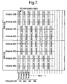
- FIG. 6 in combination with FIG. 7 , illustrates an example of simultaneous interrogation wherein the eight antennas interrogate in two groups of four (in other words, at any given time, up to four antennas are simultaneously transmitting and receiving).
- the two groups of antennas shown in FIG. 6 have been selected so as to maximise the isolation between antennas transmitting/receiving in the same time slot.
- antennas 105 , 205 , 302 and 402 simultaneously transmit and receive the signals.
- This combination of antennas results in minimum interference.
- the second group of antennas 102 , 202 , 305 and 405 then transmits and receives signals. Again, this combination of antennas results in minimum interference.
- a first measurement of all eight tires in a given angular position is thereby taken. However, the process is then repeated so that multiple measurements are taken. For a vehicle moving at 3 miles per hour, it is anticipated that up to 40 measurements are taken by each antenna. The measurements from each array for a particular tire may then be interpreted so as to provide a final pressure and temperature reading. It will be understood that, because an array of antennas is provided, at least one antenna for each tire will be ideally positioned relative to the tire sensor so as to interrogate with optimum efficiency.
- the antennas used in the aforementioned embodiments may be patch antennas, however dipole or loop antennas may also be used. Furthermore, the antennas do not need to be positioned above the road surface as schematically indicated in the accompanying drawings. Antennas may be embedded below the surface upon which the vehicle travels.
Landscapes
- Engineering & Computer Science (AREA)
- Mechanical Engineering (AREA)
- Arrangements For Transmission Of Measured Signals (AREA)
- Lock And Its Accessories (AREA)
- Radar Systems Or Details Thereof (AREA)
- Burglar Alarm Systems (AREA)
- Axle Suspensions And Sidecars For Cycles (AREA)
Applications Claiming Priority (3)
| Application Number | Priority Date | Filing Date | Title |
|---|---|---|---|
| GBGB0402240.6A GB0402240D0 (en) | 2004-02-02 | 2004-02-02 | Remote interrogation of a vehicle wheel |
| GB0402240.6 | 2004-02-02 | ||
| PCT/GB2005/000349 WO2005072993A1 (en) | 2004-02-02 | 2005-02-01 | Remote interrogation of a vehicle wheel |
Related Parent Applications (1)
| Application Number | Title | Priority Date | Filing Date |
|---|---|---|---|
| PCT/GB2005/000349 Continuation WO2005072993A1 (en) | 2004-02-02 | 2005-02-01 | Remote interrogation of a vehicle wheel |
Publications (2)
| Publication Number | Publication Date |
|---|---|
| US20070018805A1 US20070018805A1 (en) | 2007-01-25 |
| US7679501B2 true US7679501B2 (en) | 2010-03-16 |
Family
ID=31971879
Family Applications (1)
| Application Number | Title | Priority Date | Filing Date |
|---|---|---|---|
| US11/497,006 Expired - Fee Related US7679501B2 (en) | 2004-02-02 | 2006-08-01 | Remote interrogation of a vehicle wheel |
Country Status (9)
| Country | Link |
|---|---|
| US (1) | US7679501B2 (de) |
| EP (1) | EP1720721B1 (de) |
| JP (1) | JP2007520020A (de) |
| CN (1) | CN1938170B (de) |
| AT (1) | ATE432834T1 (de) |
| DE (1) | DE602005014745D1 (de) |
| GB (1) | GB0402240D0 (de) |
| TW (1) | TW200533532A (de) |
| WO (1) | WO2005072993A1 (de) |
Cited By (6)
| Publication number | Priority date | Publication date | Assignee | Title |
|---|---|---|---|---|
| US20110148593A1 (en) * | 2009-12-17 | 2011-06-23 | Robert Leon Benedict | Method for reading a vehicle tag within a read station |
| US20110148592A1 (en) * | 2009-12-17 | 2011-06-23 | Robert Leon Benedict | Antenna assembly for a tag reader |
| US20110304452A1 (en) * | 2010-06-15 | 2011-12-15 | Honda Motor Co., Ltd. | Two axis antenna for tpms sensor |
| US20130025751A1 (en) * | 2010-04-09 | 2013-01-31 | Politecnico Di Torino | Tyre sensor device |
| US9712894B2 (en) | 2014-04-29 | 2017-07-18 | General Electric Company | Passive wireless sensors |
| US9707806B2 (en) | 2015-02-06 | 2017-07-18 | Love's Travel Stops & Country Stores, Inc. | Vehicle servicing and monitoring method and system |
Families Citing this family (18)
| Publication number | Priority date | Publication date | Assignee | Title |
|---|---|---|---|---|
| JP2007216705A (ja) * | 2006-02-14 | 2007-08-30 | Bridgestone Corp | タイヤ情報取得システム |
| JP2007331522A (ja) * | 2006-06-14 | 2007-12-27 | Bridgestone Corp | タイヤ情報取得システム |
| JP5082375B2 (ja) * | 2006-10-23 | 2012-11-28 | トヨタ自動車株式会社 | 車輪状態検出ユニットの検出対象車輪特定システム |
| FR2914472B1 (fr) * | 2007-03-29 | 2010-08-13 | Siemens Vdo Automotive | Procede et dispositif de localisation de chacune des roues d'une paire de roues jumelees montees sur un vehicule |
| US20090195373A1 (en) * | 2008-01-31 | 2009-08-06 | Joseph Carmine Lettieri | Initiator system and method for a tire pressure monitoring system |
| US9000923B2 (en) | 2008-07-14 | 2015-04-07 | The Goodyear Tire & Rubber Company | Reader and method for wheel-based RFID devices |
| US7969293B2 (en) | 2008-10-13 | 2011-06-28 | The Goodyear Tire & Rubber Company | Integrated read station for a wheel-mounted vehicle |
| FR2981755B1 (fr) | 2011-10-21 | 2013-11-15 | Univ Nancy 1 Henri Poincare | Procede d'interrogation rapide d'un capteur passif, notamment du type a ondes acoustiques de surface, et systeme de mesure de la frequence propre d'un tel capteur |
| US9183423B2 (en) | 2013-07-26 | 2015-11-10 | The Goodyear Tire & Rubber Company | Drive-over stand and antenna assembly |
| US10358004B2 (en) | 2013-09-25 | 2019-07-23 | Ste S.R.L. | Device and assembly for detecting tire parameters of transiting vehicles |
| FR3039459B1 (fr) * | 2015-07-30 | 2017-08-11 | Michelin & Cie | Systeme d'evaluation de l'etat d'un pneumatique |
| TWI579536B (zh) * | 2015-12-28 | 2017-04-21 | Fang-Jun Chai | Method and device for controlling vehicle load by vehicle tire pressure detection |
| FR3067137A1 (fr) * | 2017-06-02 | 2018-12-07 | Compagnie Generale Des Etablissements Michelin | Procede de fourniture d'un service lie a l'etat et/ou au comportement d'un vehicule et/ou d'un pneumatique |
| WO2022032059A1 (en) * | 2020-08-07 | 2022-02-10 | Analog Devices, Inc. | Secure passive wireless sensor and related methods |
| US12485710B2 (en) | 2021-06-11 | 2025-12-02 | Volvo Truck Corporation | Electronic control unit (ECU) and method therein for monitoring tire sensors in a vehicle |
| WO2022258201A1 (en) * | 2021-06-11 | 2022-12-15 | Volvo Truck Corporation | A sensor array, a control unit and methods therein for locating tire sensors on a vehicle |
| US12437585B2 (en) * | 2022-11-29 | 2025-10-07 | The Goodyear Tire & Rubber Company | Tire sensor monitoring |
| JP7747937B1 (ja) | 2024-04-22 | 2025-10-02 | 克実 狩野 | 集積回路内臓タイヤ及び輸送装置の走行データ収集システム |
Citations (17)
| Publication number | Priority date | Publication date | Assignee | Title |
|---|---|---|---|---|
| US4067235A (en) | 1974-11-27 | 1978-01-10 | Consolidated Freightways, Inc. | Method and apparatus for measuring air pressure in pneumatic tires |
| GB1505804A (en) | 1976-03-02 | 1978-03-30 | Consolidated Freightways Inc | Method and apparatus for measuring air pressure in pneumatic tyres |
| US4782342A (en) * | 1986-08-04 | 1988-11-01 | Walton Charles A | Proximity identification system with lateral flux paths |
| US5289160A (en) | 1991-09-30 | 1994-02-22 | Fiorletta Carl A | Tire pressure monitoring system |
| US6016129A (en) * | 1995-04-12 | 2000-01-18 | Siemens Schweiz Ag | Antenna system, in particular an antenna system for traffic communicating systems |
| US6147659A (en) * | 1996-10-14 | 2000-11-14 | Yokohama Rubber Co., Ltd. | Tire with transponder and transponder for tire |
| US6285858B1 (en) * | 1997-11-07 | 2001-09-04 | Nec Corporation | Electronic toll collection system and method featuring antenna arrangement |
| WO2002020287A1 (en) | 2000-09-08 | 2002-03-14 | Automotive Technologies International, Inc. | Vehicle wireless sensing and communication system |
| EP1223057A2 (de) | 2001-01-11 | 2002-07-17 | The Yokohama Rubber Co., Ltd. | Transponder, Abfragegeräte und System damit |
| EP1245412A2 (de) | 2001-03-29 | 2002-10-02 | The Goodyear Tire & Rubber Company | System von Vorrichtungen zur Reifenzustandsüberwachung |
| US20020171549A1 (en) * | 2001-05-14 | 2002-11-21 | Yoshihiko Tanji | Reflection multiplier radio wave marker, marker sensor, marker system and traffic system |
| US6549125B2 (en) * | 2000-04-07 | 2003-04-15 | Trw Inc. | Tire condition sensor unit mounting arrangement |
| US20030174099A1 (en) * | 2002-01-09 | 2003-09-18 | Westvaco Corporation | Intelligent station using multiple RF antennae and inventory control system and method incorporating same |
| EP1352764A2 (de) | 2001-03-29 | 2003-10-15 | The Goodyear Tire & Rubber Company | Verfahren zur Reifenzustandsüberwachung mit einem Überfahrsensor |
| US20040239504A1 (en) * | 2001-08-23 | 2004-12-02 | Kalinin Victor Alexandrovich | Interrogation method for passive sensor monitoring system |
| US6894233B2 (en) * | 2003-02-20 | 2005-05-17 | The Revenue Markets, Inc. | Systems and methods for classifying vehicles |
| US20050110627A1 (en) * | 2003-10-02 | 2005-05-26 | Emag Technologies, Inc. | Antenna system embedded in a support structure for interrogating a tire sensor transponder |
Family Cites Families (6)
| Publication number | Priority date | Publication date | Assignee | Title |
|---|---|---|---|---|
| JPS52110682A (en) * | 1976-03-15 | 1977-09-16 | Konsorideetetsudo Furaitoueizu | Method of and apparatus for measuring air pressure in pneumatic tire |
| CN1043475A (zh) * | 1988-12-26 | 1990-07-04 | 王根友 | 轮胎工作状态监测仪 |
| US5731754A (en) * | 1994-06-03 | 1998-03-24 | Computer Methods Corporation | Transponder and sensor apparatus for sensing and transmitting vehicle tire parameter data |
| JPH10302187A (ja) * | 1997-04-25 | 1998-11-13 | Yokohama Rubber Co Ltd:The | タイヤ用トランスポンダの情報アクセス方法及びその装置 |
| JP3878280B2 (ja) * | 1997-05-27 | 2007-02-07 | 横浜ゴム株式会社 | タイヤ装着用トランスポンダ及びトランスポンダ装着タイヤ |
| JP2003182323A (ja) * | 2001-12-14 | 2003-07-03 | Sumitomo Electric Ind Ltd | タイヤ空気圧検知システム、タイヤ及びタイヤ空気圧検知装置 |
-
2004
- 2004-02-02 GB GBGB0402240.6A patent/GB0402240D0/en not_active Ceased
-
2005
- 2005-02-01 AT AT05702089T patent/ATE432834T1/de not_active IP Right Cessation
- 2005-02-01 WO PCT/GB2005/000349 patent/WO2005072993A1/en not_active Ceased
- 2005-02-01 JP JP2006551907A patent/JP2007520020A/ja active Pending
- 2005-02-01 EP EP05702089A patent/EP1720721B1/de not_active Expired - Lifetime
- 2005-02-01 DE DE602005014745T patent/DE602005014745D1/de not_active Expired - Lifetime
- 2005-02-01 CN CN2005800100795A patent/CN1938170B/zh not_active Expired - Fee Related
- 2005-02-02 TW TW094103213A patent/TW200533532A/zh unknown
-
2006
- 2006-08-01 US US11/497,006 patent/US7679501B2/en not_active Expired - Fee Related
Patent Citations (17)
| Publication number | Priority date | Publication date | Assignee | Title |
|---|---|---|---|---|
| US4067235A (en) | 1974-11-27 | 1978-01-10 | Consolidated Freightways, Inc. | Method and apparatus for measuring air pressure in pneumatic tires |
| GB1505804A (en) | 1976-03-02 | 1978-03-30 | Consolidated Freightways Inc | Method and apparatus for measuring air pressure in pneumatic tyres |
| US4782342A (en) * | 1986-08-04 | 1988-11-01 | Walton Charles A | Proximity identification system with lateral flux paths |
| US5289160A (en) | 1991-09-30 | 1994-02-22 | Fiorletta Carl A | Tire pressure monitoring system |
| US6016129A (en) * | 1995-04-12 | 2000-01-18 | Siemens Schweiz Ag | Antenna system, in particular an antenna system for traffic communicating systems |
| US6147659A (en) * | 1996-10-14 | 2000-11-14 | Yokohama Rubber Co., Ltd. | Tire with transponder and transponder for tire |
| US6285858B1 (en) * | 1997-11-07 | 2001-09-04 | Nec Corporation | Electronic toll collection system and method featuring antenna arrangement |
| US6549125B2 (en) * | 2000-04-07 | 2003-04-15 | Trw Inc. | Tire condition sensor unit mounting arrangement |
| WO2002020287A1 (en) | 2000-09-08 | 2002-03-14 | Automotive Technologies International, Inc. | Vehicle wireless sensing and communication system |
| EP1223057A2 (de) | 2001-01-11 | 2002-07-17 | The Yokohama Rubber Co., Ltd. | Transponder, Abfragegeräte und System damit |
| EP1245412A2 (de) | 2001-03-29 | 2002-10-02 | The Goodyear Tire & Rubber Company | System von Vorrichtungen zur Reifenzustandsüberwachung |
| EP1352764A2 (de) | 2001-03-29 | 2003-10-15 | The Goodyear Tire & Rubber Company | Verfahren zur Reifenzustandsüberwachung mit einem Überfahrsensor |
| US20020171549A1 (en) * | 2001-05-14 | 2002-11-21 | Yoshihiko Tanji | Reflection multiplier radio wave marker, marker sensor, marker system and traffic system |
| US20040239504A1 (en) * | 2001-08-23 | 2004-12-02 | Kalinin Victor Alexandrovich | Interrogation method for passive sensor monitoring system |
| US20030174099A1 (en) * | 2002-01-09 | 2003-09-18 | Westvaco Corporation | Intelligent station using multiple RF antennae and inventory control system and method incorporating same |
| US6894233B2 (en) * | 2003-02-20 | 2005-05-17 | The Revenue Markets, Inc. | Systems and methods for classifying vehicles |
| US20050110627A1 (en) * | 2003-10-02 | 2005-05-26 | Emag Technologies, Inc. | Antenna system embedded in a support structure for interrogating a tire sensor transponder |
Non-Patent Citations (1)
| Title |
|---|
| International Search Report, PCT/GB2005/000349 dated Mar. 5, 2005. |
Cited By (15)
| Publication number | Priority date | Publication date | Assignee | Title |
|---|---|---|---|---|
| US20110148593A1 (en) * | 2009-12-17 | 2011-06-23 | Robert Leon Benedict | Method for reading a vehicle tag within a read station |
| US20110148592A1 (en) * | 2009-12-17 | 2011-06-23 | Robert Leon Benedict | Antenna assembly for a tag reader |
| US9135479B2 (en) * | 2009-12-17 | 2015-09-15 | The Goodyear Tire & Rubber Company | Antenna assembly for a tag reader |
| US9168795B2 (en) * | 2010-04-09 | 2015-10-27 | Pirelli Tyre S.P.A. | Tyre sensor device |
| US20130025751A1 (en) * | 2010-04-09 | 2013-01-31 | Politecnico Di Torino | Tyre sensor device |
| US8497772B2 (en) | 2010-06-15 | 2013-07-30 | Honda Motor Co., Ltd. | Radio system adjustment with TPMS and smart entry system |
| US8446271B2 (en) | 2010-06-15 | 2013-05-21 | Honda Motor Co., Ltd. | Unique header format for TPMS and SMART entry system |
| US8497771B2 (en) | 2010-06-15 | 2013-07-30 | Honda Motor Co., Ltd. | Localization of tire for TPMS and smart entry system |
| US8564428B2 (en) | 2010-06-15 | 2013-10-22 | Honda Motor Co., Ltd. | Memorizing location of tires in TPMS and smart entry system |
| US8686847B2 (en) * | 2010-06-15 | 2014-04-01 | Honda Motor Co., Ltd. | Two axis antenna for TPMS sensor |
| US8344869B2 (en) | 2010-06-15 | 2013-01-01 | Honda Motor Co., Ltd. | Door open detection for use with TPMS and smart entry system |
| US20110304452A1 (en) * | 2010-06-15 | 2011-12-15 | Honda Motor Co., Ltd. | Two axis antenna for tpms sensor |
| US9399376B2 (en) | 2010-06-15 | 2016-07-26 | Honda Motor Co., Ltd. | Recognizing tire sensor location in factory mode for TPMS and smart entry system |
| US9712894B2 (en) | 2014-04-29 | 2017-07-18 | General Electric Company | Passive wireless sensors |
| US9707806B2 (en) | 2015-02-06 | 2017-07-18 | Love's Travel Stops & Country Stores, Inc. | Vehicle servicing and monitoring method and system |
Also Published As
| Publication number | Publication date |
|---|---|
| ATE432834T1 (de) | 2009-06-15 |
| CN1938170A (zh) | 2007-03-28 |
| US20070018805A1 (en) | 2007-01-25 |
| EP1720721A1 (de) | 2006-11-15 |
| DE602005014745D1 (de) | 2009-07-16 |
| GB0402240D0 (en) | 2004-03-03 |
| CN1938170B (zh) | 2010-08-25 |
| WO2005072993A1 (en) | 2005-08-11 |
| JP2007520020A (ja) | 2007-07-19 |
| EP1720721B1 (de) | 2009-06-03 |
| TW200533532A (en) | 2005-10-16 |
Similar Documents
| Publication | Publication Date | Title |
|---|---|---|
| EP1720721B1 (de) | Fernabfrage eines fahrzeugsrads | |
| US7911324B2 (en) | Method and system for obtaining information about RFID-equipped objects | |
| CN105765603B (zh) | 用于从应答器动态读取数据的系统 | |
| US20090027183A1 (en) | Tire Localization System | |
| US20070035387A1 (en) | Capacitive pressure sensor | |
| CN105830089B (zh) | 用于从应答器动态读取数据的系统 | |
| US20100265801A1 (en) | Timing system and method of timing | |
| US20110012723A1 (en) | Embedded in tire self-powered semi-passive rfid transponder | |
| WO2005036694A3 (en) | Antenna system embedded in a support structure for interrogating a tire sensor transponder | |
| US20130300543A1 (en) | Multi-element rfid coupler | |
| EP3999363B1 (de) | Fahrzeugsreifenvorrichtung zur messung der reifenhöhe und -aufstandsfläche durch ein radar im millimeterwellenbereich | |
| ES2183643T3 (es) | Disposicion para tramitar señales desde un dispositivo de vigilancia de la presion de los neumaticos en ruedas de vehiculos hasta un aparato de evaluacion dispuesto en el vehiculo. | |
| JP4585357B2 (ja) | タイヤ情報転送装置、タイヤ情報転送方法および車両 | |
| JP7174668B2 (ja) | 電子機器、電子機器の制御方法、及び電子機器の制御プログラム | |
| US20080278288A1 (en) | Rfid to Store Saw Calibration Coefficients | |
| US20040041698A1 (en) | Code learning device for tire pressure monitor | |
| JPH10302187A (ja) | タイヤ用トランスポンダの情報アクセス方法及びその装置 | |
| WO2001022118A3 (en) | System and method for locating radio frequency identification tags using three-phase antenna | |
| JP5339925B2 (ja) | タイヤ情報監視システム | |
| JP6277478B2 (ja) | 車両の車輪監視システムの通信装置および通信方法 | |
| SE534937C2 (sv) | RFID system för identifiering av tåg | |
| US7948365B2 (en) | Tire air pressure monitoring system | |
| US20220013912A1 (en) | Apparatus, and system of a stack series fed antenna including a plurality of antenna layers | |
| JP3511600B2 (ja) | 逓倍反射式電波式マーカシステム及び交通システム | |
| US20250300355A1 (en) | Device and method for reading identifiers of moving objects |
Legal Events
| Date | Code | Title | Description |
|---|---|---|---|
| AS | Assignment |
Owner name: MICHELIN RECHERCHE ET TECHNIQUE S.A., SWITZERLAND Free format text: ASSIGNMENT OF ASSIGNORS INTEREST;ASSIGNORS:DIXON, BRYN JAMES;KALININ, VICTOR ALEXANDROVICH;BECKLEY, JOHN PETER;REEL/FRAME:018226/0090 Effective date: 20060821 Owner name: MICHELIN RECHERCHE ET TECHNIQUE S.A.,SWITZERLAND Free format text: ASSIGNMENT OF ASSIGNORS INTEREST;ASSIGNORS:DIXON, BRYN JAMES;KALININ, VICTOR ALEXANDROVICH;BECKLEY, JOHN PETER;REEL/FRAME:018226/0090 Effective date: 20060821 |
|
| FEPP | Fee payment procedure |
Free format text: PAYOR NUMBER ASSIGNED (ORIGINAL EVENT CODE: ASPN); ENTITY STATUS OF PATENT OWNER: LARGE ENTITY |
|
| REMI | Maintenance fee reminder mailed | ||
| LAPS | Lapse for failure to pay maintenance fees | ||
| STCH | Information on status: patent discontinuation |
Free format text: PATENT EXPIRED DUE TO NONPAYMENT OF MAINTENANCE FEES UNDER 37 CFR 1.362 |
|
| STCH | Information on status: patent discontinuation |
Free format text: PATENT EXPIRED DUE TO NONPAYMENT OF MAINTENANCE FEES UNDER 37 CFR 1.362 |
|
| FP | Lapsed due to failure to pay maintenance fee |
Effective date: 20140316 |