US7758030B2 - Positioning apparatus and clamping system having the same - Google Patents
Positioning apparatus and clamping system having the same Download PDFInfo
- Publication number
- US7758030B2 US7758030B2 US10/575,904 US57590404A US7758030B2 US 7758030 B2 US7758030 B2 US 7758030B2 US 57590404 A US57590404 A US 57590404A US 7758030 B2 US7758030 B2 US 7758030B2
- Authority
- US
- United States
- Prior art keywords
- pressing member
- radial direction
- diametrically
- positioning
- positioning apparatus
- Prior art date
- Legal status (The legal status is an assumption and is not a legal conclusion. Google has not performed a legal analysis and makes no representation as to the accuracy of the status listed.)
- Expired - Fee Related, expires
Links
Images


Classifications
-
- B—PERFORMING OPERATIONS; TRANSPORTING
- B23—MACHINE TOOLS; METAL-WORKING NOT OTHERWISE PROVIDED FOR
- B23Q—DETAILS, COMPONENTS, OR ACCESSORIES FOR MACHINE TOOLS, e.g. ARRANGEMENTS FOR COPYING OR CONTROLLING; MACHINE TOOLS IN GENERAL CHARACTERISED BY THE CONSTRUCTION OF PARTICULAR DETAILS OR COMPONENTS; COMBINATIONS OR ASSOCIATIONS OF METAL-WORKING MACHINES, NOT DIRECTED TO A PARTICULAR RESULT
- B23Q3/00—Devices holding, supporting, or positioning work or tools, of a kind normally removable from the machine
- B23Q3/18—Devices holding, supporting, or positioning work or tools, of a kind normally removable from the machine for positioning only
-
- B—PERFORMING OPERATIONS; TRANSPORTING
- B23—MACHINE TOOLS; METAL-WORKING NOT OTHERWISE PROVIDED FOR
- B23Q—DETAILS, COMPONENTS, OR ACCESSORIES FOR MACHINE TOOLS, e.g. ARRANGEMENTS FOR COPYING OR CONTROLLING; MACHINE TOOLS IN GENERAL CHARACTERISED BY THE CONSTRUCTION OF PARTICULAR DETAILS OR COMPONENTS; COMBINATIONS OR ASSOCIATIONS OF METAL-WORKING MACHINES, NOT DIRECTED TO A PARTICULAR RESULT
- B23Q1/00—Members which are comprised in the general build-up of a form of machine, particularly relatively large fixed members
- B23Q1/0063—Connecting non-slidable parts of machine tools to each other
- B23Q1/0081—Connecting non-slidable parts of machine tools to each other using an expanding clamping member insertable in a receiving hole
- B23Q1/009—Connecting non-slidable parts of machine tools to each other using an expanding clamping member insertable in a receiving hole the receiving hole being cylindrical or conical
-
- B—PERFORMING OPERATIONS; TRANSPORTING
- B23—MACHINE TOOLS; METAL-WORKING NOT OTHERWISE PROVIDED FOR
- B23Q—DETAILS, COMPONENTS, OR ACCESSORIES FOR MACHINE TOOLS, e.g. ARRANGEMENTS FOR COPYING OR CONTROLLING; MACHINE TOOLS IN GENERAL CHARACTERISED BY THE CONSTRUCTION OF PARTICULAR DETAILS OR COMPONENTS; COMBINATIONS OR ASSOCIATIONS OF METAL-WORKING MACHINES, NOT DIRECTED TO A PARTICULAR RESULT
- B23Q3/00—Devices holding, supporting, or positioning work or tools, of a kind normally removable from the machine
- B23Q3/18—Devices holding, supporting, or positioning work or tools, of a kind normally removable from the machine for positioning only
- B23Q3/183—Centering devices
Definitions
- the present invention relates to an apparatus for positioning a second block such as a work pallet with respect to a first block such as a table of a machine tool, also relates to a clamping system equipped with the positioning apparatus.
- Such a positioning apparatus is in general conventionally constructed so as to fit a plug projected from a support surface of a reference member (first block) into a circular positioning hole opened on a supported surface of a movable member (second block) (for example, refer to the following Patent Document 1).
- the present invention has been made in view of the above problem, an object of which is to provide a positioning apparatus capable of conducting positioning with high accuracy.
- a positioning apparatus of a first invention is constructed as follows as illustrated in FIG. 1 through FIG. 3 , FIG. 10 or FIG. 11 for example.
- a plug member 12 inserted into a positioning hole 5 formed in a second block 2 is projected from a first block 1 .
- a plurality of slide portions 61 , 61 opposed to each other across the plug member 12 are arranged around the plug member 12 movably in a first radial direction D 1 substantially orthogonal to the opposed direction thereof.
- a first pressing member 15 is arranged outside the slide portions 61 , 61 diametrically expandably and diametrically contractibly and axially movably within a predetermined range.
- a second pressing member 19 is arranged outside the slide portions 61 , 61 and inside the first pressing member 15 diametrically expandably and diametrically contractibly and axially movably within a predetermined range.
- the first pressing member 15 or the second pressing member 19 is driven toward a base end by a drive means D, whereby the slide portions 61 , 61 expand the first pressing member 15 in a second radial direction D 2 different from the first radial direction D 1 , thereby the slide portions 61 , 61 are moved in the first radial direction D 1 with respect to the plug member 12 .
- the fitting gap G (for example, refer to FIG. 4 and FIG. 5 ) can be eliminated by the drive means D to conduct positioning. Therefore, the first pressing member is smoothly inserted into the positioning hole and also positioned with high accuracy. Further, positioning with high accuracy can be conducted in the second radial direction, and positional misalignment of the positioning hole to the plug member in the first radial direction is allowed, because the slide portions slide.
- the first pressing member or the second pressing member whose axial movement is allowed within a predetermined range is prevented from moving toward the base end, the first pressing member is allowed to strongly press an inner peripheral surface of the positioning hole, thereby making it possible to accomplish positioning in the second radial direction with high accuracy.
- An inclined outer surface 13 is formed on the second pressing member 19 .
- An inclined inner surface 17 allowed to make a tapering engagement with the inclined outer surface 13 is formed on the first pressing member 15 .
- a drive member 21 is inserted into the plug member 12 axially movably, and the drive member 21 is connected to the first pressing member 15 or the second pressing member 19 .
- the first pressing member 15 or the second pressing member 19 is moved toward the base end for locking via the drive member 21 so as to expand the first pressing member 15 in the second radial direction D 2 by the tapering engagement and bring the first pressing member 15 into close contact with an inner peripheral surface of the positioning hole 5 .
- the first pressing member 15 or the second pressing member 19 is moved toward a leading end for releasing via the drive member 21 so as to cancel the diametrically expanded condition of the first pressing member 15 and cancel the closely contacted condition.
- the second block is allowed to be positioned in the second radial direction with respect to the first block reliably and strongly by diametrically expanding force applied by the tapering engagement. Further, when the drive member is driven to move the first pressing member or the second pressing member for locking, the second block is allowed to be pressed against the first block via the first pressing member, thereby making it possible to omit an exclusive clamping means.
- An advancing means 69 which advances the first pressing member 15 or the second pressing member 19 toward a leading end is provided.
- the first pressing member attempts to move the second pressing member (or the first pressing member) toward a base end, to which the advancing means resists. Therefore, the first pressing member is smoothly expanded in a diametrically expanding direction. Further, the first pressing member which is in close contact with the positioning hole is allowed to move toward the base end against the advancing means by the diametrical expansion, thereby making it possible to strongly clamp the second block with respect to the first block.
- a positioning apparatus of a fourth invention is constructed as follows, for example, as illustrated in FIG. 12 and FIG. 13 , FIG. 14 , FIG. 15 and FIG. 16 , or FIG. 19 .
- a plug member 12 inserted into a positioning hole 5 formed in a second block 2 is projected from a first block 1 .
- a plurality of slide portions 61 , 61 opposed to each other across the plug member 12 are arranged around the plug member 12 movably in a first radial direction D 1 substantially orthogonal to the opposed direction thereof and axially movably within a predetermined stroke.
- a pressing member 15 is arranged outside the slide portions 61 , 61 diametrically expandably and diametrically contractibly and axially movably.
- the pressing member 15 is driven toward a base end by a drive means D, whereby the slide portions 61 , 61 diametrically expand the pressing member 15 in a second radial direction D 2 different from the first radial direction D 1 , thereby the slide portions 61 , 61 are moved in the first radial direction D 1 with respect to the plug member 12 .
- the fitting gap G (for example, refer to FIG. 12 and FIG. 13 ) is allowed to be eliminated by the drive means D to conduct positioning. Therefore, the pressing member is smoothly inserted into the positioning hole and also positioned with high accuracy. Further, positioning with high accuracy can be conducted in the second radial direction, and positional misalignment of the positioning hole to the plug member in the first radial direction is allowed, because the slide portions slide. It is noted that, when the slide portions whose axial movement is allowed within a predetermined stroke is prevented from moving toward the base end, the pressing member is allowed to strongly press an inner peripheral surface of the positioning hole, thereby making it possible to accomplish positioning in the second radial direction with high accuracy.
- Inclined outer surfaces 13 are formed on the slide portions 61 , 61 .
- An inclined inner surface 17 allowed to make a tapering engagement with the inclined outer surfaces 13 is formed on the pressing member 15 .
- a drive member 21 is inserted into the plug member 12 axially movably, and the drive member 21 is connected to the pressing member 15 .
- the drive member 21 moves the pressing member 15 toward the base end for locking to expand the pressing member 15 in the second radial direction D 2 by the tapering engagement and bring the pressing member 15 into close contact with an inner peripheral surface of the positioning hole 5 .
- the drive member 21 moves the pressing member 15 toward a leading end for releasing to cancel the diametrically expanded condition of the pressing member 15 and cancel the closely contacted condition.
- the fifth invention it is possible to position the second block with respect to the first block in the second radial direction reliably and strongly by diametrically expanding force applied from the tapering engagement. Further, when the drive member is driven to move the pressing member for locking, the second block is allowed to be pressed against the first block via the pressing member, thereby making it possible also to omit an exclusive clamping means.
- an advancing means 69 which advances the slide portions 61 , 61 toward a leading end, for example, as illustrated in FIG. 12 and FIG. 13 , FIG. 14 , FIG. 15 and FIG. 16 , or FIG. 19 .
- the pressing member attempts to move the slide portions toward the base end, to which the advancing means resists. Therefore, the pressing member is smoothly expanded diametrically. Further, by moving the pressing member which is in close contact with the positioning hole by the diametrical expansion toward the base end against the advancing means, it is possible to strongly clamp the second block with respect to the first block.
- the first pressing member or pressing member 15 is formed into an annular shape, for example, as illustrated in FIG. 1 through FIG. 3 , FIG. 10 , FIG. 11 , FIG. 12 and FIG. 13 , or FIG. 14 .
- the seventh invention it is structurally possible to prevent intrusion of foreign matter inside the first pressing member (or the pressing member) and also avoid troubles on the positioning apparatus resulting from the foreign matter.
- the seventh invention it is preferable to provide the following construction, for example, as illustrated in FIG. 1 through FIG. 3 , FIG. 10 , FIG. 11 , FIG. 12 and FIG. 13 , or FIG. 14 .
- a slit 51 is formed in the first pressing member or pressing member 15 , and the first pressing member or the pressing member 15 is allowed to deform in a diametrically expanding direction and a diametrically contracting direction by existence of the slit 51 .
- the eighth invention such a mechanically simple construction is accomplished that the first pressing member (or the pressing member) is allowed to be deformed in a diametrically expanding direction and a diametrically contracting direction. Further, the first pressing member (or the pressing member) is allowed to be deformed to a larger amount in a radial direction, thereby making the fitting gap larger to smoothly insert the first pressing member (or the pressing member) into the positioning hole.
- the second pressing member 19 is formed into an annular shape, for example, as illustrated in FIG. 1 through FIG. 3 , FIG. 10 , or FIG. 11 .
- the ninth invention it is structurally possible to prevent intrusion of foreign matter inside the second pressing member and also avoid troubles on the positioning apparatus resulting from the foreign matter.
- a slit 57 is formed in the second pressing member 19 , and the second pressing member 19 is allowed to deform in a diametrically expanding direction and a diametrically contracting direction by existence of the slit 57 .
- the second pressing member is allowed to deform in a diametrically expanding direction and a diametrically contracting direction.
- Gaps A, A are formed between the second pressing member 19 and the plug member 12 in the first radial direction D 1 .
- the first pressing member and second pressing member are movable in the first radial direction so as to smoothly absorb positional misalignment in the first radial direction occurring between the positioning hole and the plug member.
- the first invention or the fourth invention it is preferable to provide the following construction, for example, as illustrated in FIG. 15 and FIG. 16 , or FIG. 19 .
- the first pressing member or the pressing member 15 is formed into a block shape and arranged so as to oppose each other across the slide portions 61 , 61 in plurality.
- the first pressing member does not deform in a diametrically expanding direction (the second radial direction) but simply undergoes a displacement to press the inner peripheral surface of the positioning hole. Therefore, the first pressing member (or the pressing member) is deformed to a larger range and allowed to be inserted into the positioning hole more smoothly.
- Two contact portions 61 a , 61 a allowed to come into contact with an inner surface of the first pressing member or pressing member 15 and escape portion 61 b arranged between the two contact portions 61 a , 61 a are formed on an outer surface of each of the slide portions 61 circumferentially side by side.
- a gap C is formed between the escape portion 61 b and the first pressing member or pressing member 15 .
- the inner surface of the first pressing member (or the pressing member) is pushed at two contact portions for each of the slide portions but not pushed at the escape portion. Therefore, the inner surface of the first pressing member (or the pressing member) is brought into contact at two contact portions for one slide portion and, during the locking movement, the first pressing member (or the pressing member) is allowed to receive reaction force applied from the inner peripheral surface of the positioning hole at the two portions stably. It is, therefore, possible to correct appropriately and reliably positional misalignment in the second radial direction occurring between the positioning hole and the plug member.
- Two contact portions 15 a , 15 a and an escape portion 15 b arranged between the two contact portions 15 a , 15 a are formed on an outer surface of each of the first pressing member or pressing member 15 circumferentially side by side.
- a gap B is formed between the escape portion 15 b and the inner peripheral surface of the positioning hole 5 .
- the first pressing member (or the pressing member) is allowed to be appropriately positioned even in a case where the positioning hole has a larger inner diameter and the first pressing member (or the pressing member) is required to undergo a larger displacement so as to come into close contact with the inner peripheral surface of the positioning hole.
- the inner peripheral surface of the positioning hole is pushed at two contact portions for each of the first pressing members (or the pressing member), whereas not pushed at the escape portion. Therefore, diametrically expanding force (force in the second radial direction) is applied at two contact portions each for one first pressing member (or one pressing member) to correct positional misalignment in the second radial direction occurring between the positioning hole and the plug member appropriately and reliably.
- a cylindrical connecting member 81 is arranged around an outer periphery of the plug member 12 .
- the first pressing member or pressing member 15 is supported on the connecting member 81 movably in the second radial direction D 2 .
- a simple construction is realized for supporting the first pressing member (or the pressing member) formed into a block shape. Further, the connecting member is driven by a drive means, by which the first pressing member (or the pressing member) is allowed to be easily moved for locking or releasing.
- the connecting member is formed into a cylindrical shape, thereby a construction is provided that intrusion of foreign matter inside of the connecting member is made difficult.
- a returning member 84 which applies diametrically contracting force to the first pressing member or pressing member 15 is provided, for example, as illustrated in FIG. 15 and FIG. 16 , or FIG. 19 .
- the first pressing member (or the pressing member) formed into a block shape is allowed to easily return to a non diametrically-expanded condition.
- the first invention or the fourth invention it is preferable to provide the following construction, for example, as illustrated in FIG. 2 , FIG. 10 , FIG. 11 , FIG. 12 , FIG. 14 , or FIG. 15 .
- the drive means D moves the second block 2 toward a base end via the first pressing member or pressing member 15 in such a condition that the first pressing member or pressing member 15 comes into close contact with an inner peripheral surface of the positioning hole 5 , and presses a supported surface 2 a of the second block 2 against a support surface 1 a of the first block 1 .
- the second block is allowed to be positioned in the second radial direction with respect to the first block and also to be restricted in the axial direction.
- the clamping system of the present invention is provided with the clamping apparatus set forth in the first invention or the fourth invention.
- the clamping system of the present invention is constructed in such a way that a plurality of positioning apparatuses are provided, and at least one of them is the positioning apparatus as set forth in the first invention or the fourth invention.
- FIG. 1 is a plan view illustrating a plug means of a positioning apparatus according to a first embodiment of the present invention.
- FIG. 2 is a cross sectional view indicated by the arrow 2 - 2 in FIG. 1 .
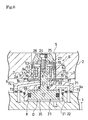
- FIG. 3 is a cross sectional view indicated by the arrow 3 - 3 in FIG. 2 .
- FIG. 4 is an elevational cross sectional view illustrating a state in which the plug means is inserted into a positioning hole.
- FIG. 5 is a cross sectional view indicated by the arrow 5 - 5 in FIG. 4 .
- FIG. 6 is an elevational cross sectional view illustrating a state in which a sleeve member of the plug means diametrically expands to come into close contact with an inner peripheral surface of the positioning hole.
- FIG. 7 is a cross sectional view indicated by the arrow 7 - 7 in FIG. 6 .
- FIG. 8 is an elevational cross sectional view illustrating a state that the sleeve member strongly and diametrically expands.
- FIG. 9 is a comparative view explaining effects of the positioning apparatus, corresponding to FIG. 3 .
- FIG. 10 is a view illustrating a second embodiment of the present invention and similar to FIG. 2 .
- FIG. 11 is a view illustrating a third embodiment of the present invention and similar to FIG. 4 .
- FIG. 12 is a view illustrating a fourth embodiment of the present invention and similar to FIG. 4 .
- FIG. 13 is a cross sectional view indicated by the arrow 13 - 13 in FIG. 12 .
- FIG. 14 is a view illustrating a fifth embodiment of the present invention and similar to FIG. 4 .
- FIG. 15 is a view illustrating a sixth embodiment of the present invention and similar to FIG. 4 .
- FIG. 16 is a cross sectional view indicated by the arrow 16 - 16 in FIG. 15 .
- FIG. 17 is a cross sectional view illustrating a state that the engaging member illustrated in FIG. 16 is in close contact with an inner peripheral surface of the positioning hole.
- FIG. 18 is an enlarged view illustrating major parts of FIG. 17 .
- FIG. 19 is a view illustrating a seventh embodiment of the present invention and similar to FIG. 16 .
- FIG. 20 is a schematic plan view illustrating a first example of the clamping system.
- FIG. 21 is a schematic plan view illustrating a second example of the clamping system.
- FIG. 1 through FIG. 8 illustrate a first embodiment of the present invention.
- FIG. 1 is a plan view of a plug means of the positioning apparatus.
- FIG. 2 is a view indicated by the arrow 2 - 2 in FIG. 1 .
- FIG. 3 is a cross sectional view indicated by the arrow 3 - 3 in FIG. 2 .
- a base plate 1 as a first block is placed and fixed to a table T of a machine tool.
- a circular positioning hole 5 in a penetrating manner.
- a plug means 6 Corresponding to the positioning hole 5 , on the base plate 1 is provided a plug means 6 .
- an installation hole 8 in an upper surface of the base plate 1 is formed an installation hole 8 .
- a housing 9 is fitted into the installation hole 8 in a precisely positioned condition.
- a flange 9 a of the housing 9 is fixed to the base plate 1 by a plurality of tightening bolts 10 (refer to FIG. 1 ).
- a plug member 12 is projected from the housing 9 upward (toward a leading end).
- the plug member 12 is allowed to be inserted into the positioning hole 5 .
- An axis of the plug member 12 coincides with an axis of the installation hole 8 .
- a periphery of the plug member 12 On a periphery of the plug member 12 are projected a plurality of bosses 1 b (in the present embodiment, four bosses 1 b as illustrated in FIG. 1 ) from the flange 9 a upward. On an upper end surface of the boss 1 b is formed a flat support surface 1 a .
- the positioning apparatus of the present embodiment is constructed in such a way that a supported surface 2 a of the work pallet 2 as the second block is received by the support surface 1 a of the base plate 1 and the work pallet 2 is positioned with respect to the base plate 1 .
- a pair of slide outer surfaces 64 , 64 facing each other in a radical direction On an outer periphery of the plug member 12 is formed a pair of slide outer surfaces 64 , 64 facing each other in a radical direction.
- the slide outer surfaces 64 , 64 are formed into a vertical flat surface which is parallel to the axis of the plug member 12 .
- the slide portions 61 , 61 are arranged so as to oppose each other across the plug member 12 in a radial direction.
- slide surfaces 63 , 63 On inner surfaces of the respective slide portions 61 , 61 are formed slide surfaces 63 , 63 .
- the slide surface 63 is also formed into a vertical flat surface which is parallel to the axis of the plug member 12 , as with the slide outer surface 64 .
- the slide portions 61 , 61 are arranged in such a way that the slide surfaces 63 , 63 come into contact with the slide outer surfaces 64 , 64 , and allowed to move toward a first radial direction (first diametrically direction) D 1 given in FIG. 3 , along the slide surfaces 63 , 63 .
- outer surfaces of the respective slide portions 61 , 61 are formed into an arc surface which is made straight vertically (straight outer surface).
- An annular wedge member 19 (second pressing member) is arranged outside the slide portions 61 , 61 and around an outer periphery of the plug member 12 .
- An inner surface of the wedge member 19 comes into contact with the straight outer surface of the slide portions 61 , 61 .
- the inner surface of the wedge member 19 slides on the straight outer surface, by which the wedge member 19 is allowed to move axially within a predetermined movable stroke to be described later.
- the wedge member 19 is formed into a collet shape. Namely, on a peripheral wall 19 a of the wedge member 19 is provided one slit 57 extending axially and opened on both upper and lower ends. Thereby, a substantially whole part of the peripheral wall 19 a which extends circumferentially is allowed to undergo an elastic deformation in a diametrically expanding direction and a diametrically contracting direction.
- the inclined outer surface 13 is constructed into a tapered shape so as to get closer to the axis upward (toward the leading end).
- gaps A, A in the first radial direction D 1 are formed between the wedge member 19 and the plug member 12 .
- an annular sleeve member (first pressing member) 15 Outside the wedge member 19 is arranged an annular sleeve member (first pressing member) 15 .
- the sleeve member 15 is also formed into a collet shape, as with the wedge member 19 . Namely, on a peripheral wall 15 a of the sleeve member 15 is provided one slit 51 extending axially and opened on both upper and lower ends. Thereby, a substantially whole part of the peripheral wall 19 a which extends circumferentially is allowed to undergo an elastic deformation in a diametrically expanding direction and a diametrically contracting direction. In addition, when the sleeve member 15 is released for diametrically expanding force thereof, the sleeve member 15 is allowed to return to a diametrically contracting direction by its own elastic restoring force.
- an inclined inner surface 17 Over an entire inner periphery of the sleeve member 15 is formed an inclined inner surface 17 .
- the inclined inner surface 17 is formed into a tapered shape so as to get closer to the axis upward (toward the leading end).
- the inclined inner surface 17 is allowed to make a tapering engagement with the inclined outer surface 13 of the wedge member 19 .
- a straight outer surface 16 Over an entire outer periphery of the sleeve member 15 is formed a straight outer surface 16 , which is allowed to come into close contact with the positioning hole 5 .
- the slit 51 is not limited to a single slit but may be available in plurality.
- the slits 51 may be opened on both the upper and lower ends of the sleeve member 15 alternately and circumferentially.
- the slit 57 is not limited to a single slit but may be available in plurality.
- a rotation stopper pin 52 is fixed to the wedge member 19 , and an outer end of the rotation stopper pin 52 projecting in a radial direction is inserted into the slit 51 of the sleeve member 15 . Consequently, rotation of the sleeve member 15 is prevented.
- an elastic seal member (not illustrated) such as rubber is accommodated in the slit 51 by adhesion, packing or the like.
- the elastic seal member may be omitted, depending on an application of the positioning apparatus.
- the drive member 21 is provided with a piston 22 inserted hermetically into a lower part of the housing 9 , a piston rod 23 projected upward from the piston 22 , a bolt 24 screwed onto an upper part of the piston rod 23 , a cap member 25 fixed by the bolt 24 , and a ring 26 attached between the cap member 25 and an upper end surface of the piston rod 23 . Between the cap member 25 and the ring 26 is fitted an upper flange 27 of the sleeve member 15 horizontally movably.
- a pin 55 is inserted into the piston 22 , and the pin 55 is engaged with an engaging hole formed on the housing 9 . As a result, rotation of the drive member 21 is blocked.
- the lock means 31 is constructed with a hydraulic chamber 34 provided for locking (hereinafter, referred to as a lock chamber) arranged above the piston 22 and with the piston 22 .
- the release means 32 is constructed with a hydraulic chamber 35 provided for releasing (hereinafter, referred to as a release chamber) provided below the piston 22 and with the piston 22 .
- the lock chamber 34 is communicatively connected with a lock port 72 formed at a lower surface of the flange 9 a via an oil passage 71 formed inside the housing 9 . Further, the release chamber 35 is communicatively connected with a bottom portion of the installation hole 8 .
- blow port 73 On the lower surface of the flange 9 a is provided a blow port 73 .
- the blow port 73 is communicatively connected with inside of the cylindrical hole of the plug member 12 via an air passage 74 formed inside the housing 9 .
- an outer peripheral surface of the piston rod 23 is notched to form a vertical passage 75 , and the vertical passage 75 is communicatively connected with the air passage 74 .
- a positioning detection port 85 on the lower surface of the flange 9 a is provided a positioning detection port 85 .
- the positioning detection port 85 is communicatively connected with a nozzle hole 87 opened in the support surface 1 a of the boss 1 b via an air passage 86 formed inside the housing 9 .
- the nozzle hole 87 is closed by the supported surface 2 a , thereby resulting in pressure rise of the positioning detection port 85 .
- an annular shallow recess is formed on an upper part of the outer peripheral surface of the sleeve member 15 , and an annular cover member 53 is fitted into the recess.
- the cover member 53 is formed in a circumferentially seamless manner, covering outside of an upper portion of the slit 51 .
- An upper end surface of the cover member 53 is in contact with a lower end surface of the cap member 25 .
- the cover member 53 acts to prevent intrusion of foreign matter such as metal swarf inside of the sleeve member 15 .
- annular gap Between the upper flange 27 of the sleeve member 15 and the ring 26 is formed an annular gap.
- the annular gap allows the sleeve member 15 to deform and move in a diametrically expanding direction and a diametrically contracting direction.
- a coned disc spring 69 As an advancing means.
- the coned disc spring 69 exerts resilient force in the direction which allows the wedge member 19 to advance upward (toward the leading end). In other words, the coned disc spring 69 exerts force in the direction so as to tighten a tapering engagement between the inclined outer surface 13 and the inclined inner surface 17 .
- the wedge member 19 is prevented from ascending to an amount exceeding the predetermined amount by being blocked by a flange 70 formed into an annular shape on an outer periphery of a leading end of the plug member 12 . Accordingly, an upper end (leading end) of the movable stroke of the wedge member 19 is regulated.
- an annular projection 58 is formed on an outer periphery of a lower end portion of the plug member 12 . Then, when the wedge member 19 is lowered to compress the coned disc spring 69 in a predetermined amount, the coned disc spring 69 comes into contact with the projection 58 , thereby preventing additional compression. Accordingly, a lower end (base end) of the movable stroke of the wedge member 19 is regulated.
- FIG. 2 and FIG. 3 , and FIG. 4 through FIG. 8 An explanation will be made for operation of the positioning apparatus by referring to FIG. 2 and FIG. 3 , and FIG. 4 through FIG. 8 .
- FIG. 4 is an elevational cross sectional view illustrating a state in which the plug means 6 is inserted into the positioning hole 5 .
- FIG. 5 is a cross sectional view indicated by the arrow 5 - 5 in FIG. 4 .
- FIG. 6 is an elevational cross sectional view illustrating a state in which the sleeve member 15 diametrically expands to come into close contact with the inner peripheral surface of the positioning hole 5 .
- FIG. 7 is a cross sectional view indicated by the arrow 7 - 7 in FIG. 6 .
- FIG. 8 is an elevational cross sectional view illustrating a locked state.
- the wedge member 19 is raised by the operation of the coned disc spring 69 and kept stationary at a position contacting with the flange 70 (at a position corresponding to an advanced end of the movable stroke) or at a position close thereto.
- the inclined outer surface 13 of the wedge member 19 is opposed to the inclined inner surface 17 of the sleeve member 15 in a minute space or slightly makes a tapering engagement therewith. Therefore, the sleeve member 15 is in a condition completely free of elastic deformation in a diametrically expanding direction (in a condition of a minimum deformation, if any). Additionally, the condition of the sleeve member 15 is called a “non diametrically-expanded condition.”
- the work pallet 2 When the work pallet 2 is positioned with respect to the base plate 1 , at first, as illustrated in FIG. 4 , in the above-described released condition, the work pallet 2 is lowered and the straight outer surface 16 of the sleeve member 15 is inserted into the positioning hole 5 . It is desirable that during the insertion, compressed air is supplied to the blow port 73 , thereby blowing foreign matter attached on various portions such as the inner peripheral surface of the positioning hole 5 and cleaning them. Since the sleeve member 15 is in the non diametrically-expanded condition, as described previously, an annular fitting gap G is formed between the straight outer surface 16 inserted into the positioning hole 5 and the inner peripheral surface of the positioning hole 5 .
- the axis of the positioning hole 5 is misaligned to the axis of the plug member 12 , and also misaligned to the first radial direction D 1 which is parallel to the slide surface 63 and a second radial direction (second diametrically direction) D 2 which is perpendicular thereto, as illustrated in FIG. 5 .
- the fitting gap G is an eccentric gap as illustrated in FIG. 5 , as a result of the above axial misalignment.
- the pressurized oil is discharged from the release chamber 35 and also pressurized oil is supplied via the lock port 72 to the lock chamber 34 .
- the piston 22 lowers the sleeve member 15 via the bolt 24 and the ring 26 by relatively low hydraulic pressure of the lock chamber 34 .
- the sleeve member 15 pushes the wedge member 19 but the descent is resisted by the resilient force of the coned disc spring 69 .
- the inclined inner surface 17 of the sleeve member 15 is wedge-engaged with the inclined outer surface 13 of the wedge member 19 .
- the slide portions 61 , 61 allow the sleeve member 15 to expand elastically via the wedge member 19 toward the second radial direction D 2 , thereby bringing the sleeve member 15 into close contact with the inner peripheral surface of the positioning hole 5 .
- the fitting gap G illustrated in FIG. 4 and FIG. 5 is eliminated.
- the sleeve member 15 allows diametrically expanding force to act upon the inner peripheral surface of the positioning hole 5 only at portions opposing the slide portions 61 , 61 , instead of the entire circumferential direction. Therefore, regarding positional misalignment of the positioning hole 5 with respect to the plug member 12 (the positional misalignment illustrated in FIG. 5 ), the positional misalignment in the second radial direction D 2 is corrected by the close contact.
- the slide portions 61 , 61 is movable in the first radial direction D 1 along the slide surfaces 63 , 63 . Therefore, as illustrated in FIG.
- the sleeve member 15 is allowed to move to some extent toward the first radial direction D 1 , together with the wedge member 19 and the slide portions 61 , 61 by the component force of the first radial direction D 1 of reaction force applied from the inner peripheral surface of the positioning hole 5 , when the positioning hole 5 is pressed. Therefore, regarding positional misalignment of the positioning hole 5 with respect to the plug member 12 , the positional misalignment in the first radial direction D 1 is allowed.
- the plug means 6 conducts an accurate positioning in the direction at which slide portions 61 , 61 oppose each other (the second radial direction D 2 ) and allows positional misalignment in the direction orthogonal thereto (the first radial direction D 1 ).
- the drive member 21 strongly lowers the work pallet 2 via the sleeve member 15 , and the supported surface 2 a of the work pallet 2 is strongly pressed against the support surface 1 a of the base plate 1 .
- the sleeve member 15 is prevented from descending to an amount exceeding a predetermined amount by a lower surface of the ring 26 which comes into contact with the upper end surface of the plug member 12 .
- the pressurized oil may be discharged from the lock chamber 34 and also pressurized oil may be supplied to the release chamber 35 .
- the sleeve member 15 ascends by the bolt 24 and the ring 26 (release movement), and the sleeve member 15 returns to the non diametrically-expanded condition by its own elastic restoring force, while releasing the tapering engagement with the wedge member 19 , thereby the locked condition is released. Thereafter, the work pallet 2 is raised.
- positioning can be conducted by eliminating the fitting gap G (refer to FIG. 4 and FIG. 5 ) in the condition that the sleeve member 15 is inserted into the positioning hole 5 . Therefore, it is possible to smoothly and easily insert the sleeve member 15 into the positioning hole 5 and at the same time positioning with high accuracy can be conducted.
- positional misalignment of the positioning hole 5 to the plug member 12 in the first radial direction D 1 is smoothly absorbed by the slide portions 61 , 61 which slide along the slide surface 63 .
- a specific explanation will be made for effects thereof by comparison with a structural example given in FIG. 9 .
- FIG. 9 is a view illustrating a construction that the inventor proposed previously, corresponding to FIG. 3 .
- projections 91 , 91 projecting in the second radial direction D 2 are formed on an outer peripheral surface of the plug member 12 so as to oppose each other in a radial direction.
- lopsided force may be often locally applied to corners of the straight outer surface 92 of the projection 91 or to the inner peripheral surface of the wedge member 19 .
- external force in the second radial direction D 2 is applied to the work pallet 2 in a positioned condition, excessive force is applied to the partially contacted portion, and damage such as an impression may be generated on the inner peripheral surface of the wedge member 19 or the straight outer surface 92 .
- high-quality materials such as special alloy steels or to provide proper hardening process for the materials, resulting in an increased production cost.
- the projections 91 , 91 are made small to decrease a contact area between the straight outer surface 92 of the leading end surface and the inner peripheral surface of the wedge member 19 .
- the sleeve member 15 is unable to increase diametrically expanding force in the second radial direction D 2 .
- lowering force of the work pallet 2 cannot be secured sufficiently and reliably via the sleeve member 15 .
- the slide portions 61 , 61 are also 25 moved accordingly. Therefore, the straight outer surfaces of the slide portions 61 , 61 do not come into partial contact with the inner peripheral surface of the wedge member 19 . Then, the straight outer surfaces of slide portions 61 , 61 or the inner peripheral surface of the wedge member 19 is not damaged.
- the sleeve member 15 and the wedge member 19 are moved smoothly along the slide surface 63 , together with the slide portions 61 , 61 . Therefore, during the locking operation, the sleeve member 15 and the wedge member 19 follow positional misalignment in the first radial direction D 1 and lo move smoothly while sliding, thereby making it possible to smoothly absorb the positional misalignment in the first radial direction D 1 .
- This fact means that a contact area is made larger between the straight outer surface of the slide portions 61 and the inner peripheral surface of the wedge member 19 , and diametrically expanding force is made larger which is applied by the sleeve member 15 to the inner peripheral surface of the positioning hole 5 . It also means that in a condition that the sleeve member 15 is in close contact with the inner peripheral surface of the positioning hole 5 , lowering force of the work pallet 2 can be made larger.
- the sleeve member 15 presses the inner peripheral surface of the positioning hole 5 more strongly in a condition given in FIG. 8 where the wedge member 19 is prevented from moving toward the lower end than in a condition given in FIG. 6 . Therefore, an accurate positioning in the second radial direction D 2 is accomplished.
- the inclined outer surface 13 is formed on the wedge member 19 and the inclined inner surface 17 is formed on the sleeve member 15 . Therefore, the second block 2 is allowed to be positioned in the second radial direction D 2 with respect to the first block 1 more reliably and strongly by mechanical expanding force derived from the tapering engagement.
- the drive member 21 is driven by the drive means D to move the sleeve member 15 for locking, the second block 2 is allowed to be pressed against the first block 1 via the sleeve member 15 , thereby making it possible to omit an exclusive clamping means.
- the coned disc spring 69 which allows the wedge member 19 to advance to the leading end. Therefore, when the sleeve member 15 is moved to the base end for locking, the sleeve member 15 attempts to move the wedge member 19 to the base end, to which the resilient force of the coned disc spring 69 resists. Therefore, the sleeve member 15 is smoothly expanded diametrically by the tapering engagement.
- the sleeve member 15 is formed into an annular shape. Therefore, intrusion of foreign matter such as swarf inside of the sleeve member 15 is made difficult.
- the slit 51 is formed in the sleeve member 15 .
- the sleeve member 15 is constructed so as to be deformable in a diametrically expanding and diametrically contracting direction by existence of the slit 51 . Therefore, such a simple construction is realized that the sleeve member 15 is allowed to be deformed in the diametrically expanding and diametrically contracting direction. Further, as compared with a case where the sleeve member 15 is formed in a seamless manner, the sleeve member 15 is allowed to be deformed to a larger amount. Accordingly, since the fitting gap G (illustrated in FIG. 4 and FIG. 5 ) is made larger in the non diametrically-expanded condition, the straight outer surface 16 is effectively inserted into the positioning hole 5 .
- the wedge member 19 is formed into an annular shape. Therefore, intrusion of foreign matter such as swarf inside of the wedge member 19 is made difficult.
- the slit 57 is formed in the wedge member 19 .
- the wedge member 19 is constructed so as to be deformable in a diametrically expanding and diametrically contracting direction by the slit 51 . Therefore, such a simple construction is accomplished that the wedge member 15 is allowed to be deformed in the diametrically expanding and diametrically contracting direction.
- the sleeve member 15 and the wedge member 19 follow positional misalignment in the first radial direction D 1 to move smoothly while sliding, thereby making it possible to smoothly absorb the positional misalignment in the first radial direction D 1 .
- the inclined outer surface 13 may be provided on an outer surface of another member arranged outside the wedge member 19 , instead of being provided on the outer surface of the wedge member 19 .
- the slide outer surface 64 may be provided on an outer surface of another member arranged outside the plug member 12 , instead of being provided on the outer surface of the plug member 12 .
- the slit 51 is not formed in the sleeve member 15 but the sleeve member 15 may be formed into an annularly seamless. Further, the slit 57 is not formed in the wedge member 19 but the wedge member 19 may be formed in an annularly seamless manner.
- the wedge member 19 may be constructed as a plurality of divided members divided circumferentially.
- a pair of the slide portions 61 , 61 may be connected via a thin member (not illustrated) extending along the respective gaps A, A, or may be formed integrally with the thin member.
- the drive member 21 is driven vertically by hydraulic pressure. However, it may be driven by supplying compressed air to the lock chamber 34 or the release chamber 35 for example. Further, the drive member 21 is not necessarily driven by a pressurized fluid but may be driven upward or downward by using a spring for example.
- the spring may include a compression coil spring and a single or a laminated coned disc spring.
- the plug means 6 may be inserted into the positioning hole 5 by raising the base plate 1 , instead of lowering the work pallet 2 . Further, a construction may be provided that the work pallet 2 is lowered and the base plate 1 is raised at the same time.
- the positioning hole 5 in a penetrating manner, however, the positioning hole 5 may be formed into such a shape so as to be opened only in the lower surface of the work pallet 2 .
- the present embodiment may be constructed in such a way that the plug member 12 and the positioning hole 5 are arranged so that their axes are kept lateral and the plug means 6 is inserted into the positioning hole 5 horizontally.
- the plug means 6 may be inserted thereinto in an oblique direction.
- FIG. 10 is a view illustrating a second embodiment of the positioning apparatus, corresponding to FIG. 2 .
- the coned disc spring is omitted, but instead, an annular advance piston (advancing means) 69 is hermetically engaged with the housing 9 and the piston rod 23 .
- the advance piston 69 is movable vertically (axially).
- the advance piston 69 is driven upward by pressurized oil of the lock chamber 34 .
- the pressure receiving area of the advance piston 69 is smaller than that of the piston 22 of the lock chamber 34 .
- a plurality of transmission pins 76 are supported on the housing 9 so as to be movable vertically (axially). A lower end of the transmission pin 76 is in contact with the advance piston 69 , and an upper end thereof is in contact with the wedge member 19 .
- the positioning apparatus of the second embodiment is different in operation from that of the first embodiment in the following points.
- the transmission pin 76 is in a condition where it is not projected from an upper surface of the flange 9 a , and the wedge member 19 is directly received by the flange 9 a . Therefore, additional descent of the wedge member 19 (movement to the base end) is prevented, and the sleeve member 15 strongly presses the inner peripheral surface of the positioning hole 5 of the work pallet 2 in the second radial direction D 2 .
- the advance piston 69 may be driven by other pressurized fluid, for example, compressed air.
- advance piston 69 driven by the above pressurized fluid is used as an advancing means is applicable to any of a third embodiment through a seventh embodiment.
- FIG. 11 is a view illustrating a third embodiment of the positioning apparatus, corresponding to FIG. 4 .
- the third embodiment is different from the first embodiment in the following points.
- an upper surface of the flange 9 a is projected upward annularly around the base end of the plug member 12 , and an upper surface of the annular projection 1 b is given as the support surface 1 a .
- the support surface 1 a is opened the nozzle hole 87 .
- the inclined outer surface 13 of the wedge member 19 (second pressing member) is formed in an inclined manner so as to get closer to the axis of the plug member 12 downward (toward the base end).
- the inclined inner surface 17 of the sleeve member 15 (first pressing member) is formed in an inclined manner so as to get closer to the axis of the plug member 12 downward (toward the base end).
- a flange portion 77 formed at a lower part of the sleeve member 15 is allowed to come into contact with a flange 70 formed at an upper end and in a periphery of the annular projection 1 b , thereby preventing advancement of the sleeve, member 15 to an amount exceeding a predetermined amount.
- the positioning apparatus of the third embodiment is different in operation from that of the first embodiment in the following points.
- the wedge member 19 has been kept raised by the piston 22 . Further, the sleeve member 15 has been raised by the action of the coned disc spring 69 and has been kept stationary at a position contacting with the flange 70 (at a position corresponding to an advanced end of the movable stroke) or at a position close thereto.
- the wedge member 19 When the wedge member 19 is lowered by the drive member 21 during the locking drive, the wedge member 19 attempts to lower the sleeve member 15 , to which the resilient force of the coned disc spring 69 resists. As a result, the inclined outer surface 13 of the wedge member 19 is wedge-engaged with the inclined inner surface 17 of the sleeve member 15 . Thereby, the slide portions 61 , 61 elastically expand the sleeve member 15 via the wedge member 19 in the second radial direction, allowing the sleeve member 15 to come into close contact with the inner peripheral surface of the positioning hole 5 .
- the sleeve member 15 is received via the coned disc spring 69 by the housing 9 , by which additional descent of the sleeve member 15 (movement to the base end) is prevented.
- downward force applied by the drive means D to the wedge member 19 is substantially converted to diametrically expanding force of the sleeve member 15 via the inclined outer surface 13 and the inclined inner surface 17 .
- the sleeve member 15 strongly presses the inner peripheral surface of the positioning hole 5 in the second radial direction.
- FIG. 12 and FIG. 13 are views illustrating a fourth embodiment of the present invention.
- FIG. 12 is a view corresponding to FIG. 4 .
- FIG. 13 is a cross sectional view indicated by the arrow 13 - 13 in FIG. 12 , corresponding to FIG. 5 .
- the fourth embodiment is different from the first embodiment in the following points.
- the plug means 6 is not provided with the wedge member but, instead, formed with inclined outer surfaces 13 , 13 on the slide portions 61 , 61 .
- the inclined outer surfaces 13 , 13 are formed into a tapered shape so as to get closer to the axis upward (toward the leading end).
- the inclined outer surface 13 of the slide portions 61 is allowed to be directly in contact with the inclined inner surface 17 of the sleeve member 15 (pressing member).
- annular collar 54 which is formed in a circumferentially seamless manner.
- the annular collar 54 is fitted into an inner periphery at the lower part of the sleeve member 15 between the coned disc spring 69 to be described later and the slide portion 61 .
- the annular collar 54 is able to prevent intrusion of foreign matter such as swarf derived from metal working inside of the sleeve member 15 .
- Each of the slide portions 61 , 61 is arranged on the plug member 12 along the slide surface 63 in a movable condition in the first radial direction D 1 .
- the slide portions 61 are axially movable by a predetermined stroke with respect to the plug member 12 . More specifically, in order to form the slide outer surfaces 64 , 64 , a vertical dimension of a groove formed in the plug member 12 is made slightly larger than that of the slide portion 61 , by which the slide portion 61 is allowed to move vertically inside the groove by the movable stroke to be explained later.
- a coned disc spring 69 is arranged between the annular collar 54 and the flange 9 a as an advancing means.
- the coned disc spring 69 exerts resilient force in such a direction as to make the slide portions 61 , 61 advance upward (toward the leading end) via the annular collar 54 .
- the coned disc spring 69 exerts force in such a direction as to tighten the tapering engagement of the inclined outer surface 13 with the inclined inner surface 17 .
- ascent of the slide portions 61 , 61 larger than a predetermined range is prevented by a flange 70 formed on an outer periphery of the leading end of the plug member 12 .
- the limit of the movable stroke of the slide portions 61 , 61 at the upper end (leading end) is regulated.
- a restricting surface 78 for preventing movement of the slide portion 61 to the lower end is formed on a base end portion of the groove.
- the limit of the movable stroke of the slide portions 61 , 61 at the lower end (base end) is regulated.
- the positioning apparatus of the fourth embodiment is different in operation from that of the first embodiment in the following points.
- the sleeve member 15 has been kept raised by the piston 22 .
- the slide portions 61 , 61 has been raised by the action of the coned disc spring 69 and has been kept stationary at a position contacting with the flange 70 (at a position corresponding to an advanced end of the movable stroke) or at a position close thereto.
- the sleeve member 15 When the sleeve member 15 is lowered by the drive member 21 during the locking drive, the sleeve member 15 attempts to lower the slide portions 61 , 61 , to which resilient force of the coned disc spring 69 resists. As a result, the inclined inner surface 17 of the sleeve member 15 is wedge-engaged with the inclined outer surface 13 of the slide portions 61 , 61 . Thereby, the sleeve member 15 elastically expands diametrically in the second radial direction D 2 , coming into close contact with the inner peripheral surface of the positioning hole 5 . Then, regarding positional misalignment of the positioning hole 5 with respect to the plug member 12 , the positional misalignment in the second radial direction D 2 is corrected.
- the slide portions 61 , 61 is movable along the slide surfaces 63 , 63 in the first radial direction D 1 , thereby the sleeve member 15 is allowed to move to some extent toward the first radial direction D 1 , together with the slide portions 61 , 61 by the component force of the first radial direction D 1 of reaction force applied from the inner peripheral surface of the positioning hole 5 , when the sleeve member 15 comes into close contact with the inner peripheral surface of the positioning hole 5 . Therefore, regarding positional misalignment of the positioning hole 5 with respect to the plug member 12 , the positional misalignment in the first radial direction D 1 is allowed.
- a wedge member necessary in the first embodiment through the third embodiment can be omitted to provide a simple construction.
- a pair of the slide portions 61 , 61 and the annular collar 54 may be formed integrally, instead of being formed separately.
- a pair of the slide portions 61 , 61 may be connected via a thin member (not illustrated) extending along the gaps A, A or formed integrally with the thin member.
- FIG. 14 is a view illustrating a fifth embodiment of the present invention, corresponding to FIG. 4 .
- the fifth embodiment is given as an exemplary variation of the fourth embodiment. As illustrated in FIG. 14 , no boss is projected on the base plate 1 , instead, an upper surface of the flange 9 a on the housing 9 is annularly projected to construct the support surface 1 a on an upper end surface of the annular projection 1 b .
- a screw hole 66 opened in the upper end surface of the plug member 12 is screwed a lower part of a flanged bolt 67 .
- a hexagonal hole (not illustrated), and a hexagon wrench 68 is allowed to be engaged with the hole as illustrated by the chain line.
- the cap member 25 relatively rotatably and vertically unmovably.
- an upper flange 27 of the sleeve member 15 is fitted into a engaging recess 56 formed at the lower part of the cap member 25 .
- the flanged bolt 67 corresponds to the drive member 21 .
- the drive means D is constructed with the screw hole 66 and the hexagon wrench 68 .
- Such a construction that a screw member such as a bolt 67 is used as a drive member as described in the present embodiment is applicable to other embodiments as well illustrated in the present specification.
- FIG. 15 through FIG. 18 are views illustrating a sixth embodiment of the present invention.
- FIG. 15 is a view corresponding to FIG. 4 .
- FIG. 16 is a cross sectional view indicated by the arrow 16 - 16 in FIG. 15 .
- FIG. 17 is a cross sectional view illustrating a state that the engaging member 15 undergoes displacement in a diametrically expending direction to come into close contact with the inner peripheral surface of the positioning hole 5 .
- FIG. 18 is an enlarged view illustrating major parts of FIG. 17 .
- the sixth embodiment is given as an exemplary variation of the fourth embodiment ( FIG. 12 and FIG. 13 ).
- a cylindrical connecting member 81 On a cylindrical wall of the connecting member 81 is formed a support window 82 which opposes the inclined outer surface 13 of the slide portion 61 .
- a pair of the engaging members 15 , 15 pressing members which is constructed into a block shape radially movably.
- These engaging members 15 , 15 are arranged to oppose each other in a radial direction so as to hold both the slide portions 61 , 61 therebetween. Further, on each of the engaging members 15 , 15 is formed an inclined inner surface 17 , and the inclined inner surface 17 is allowed to make a tapering engagement with the inclined outer surface 13 of the slide portion 61 . Both the inclined outer surface 13 and the inclined inner surface 17 are formed into tapered surfaces so as to get closer to the axis toward the leading end.
- each engaging member 15 On each engaging member 15 is formed a straight outer surface 16 .
- fine serrate irregularities are formed on the straight outer surface 16 , as illustrated in FIG. 15 .
- the irregularities provide a large friction to strongly lower the work pallet 2 via the engaging members 15 , 15 .
- the straight outer surfaces 16 , 16 may be formed into a flat surface.
- a through hole 83 is circumferentially formed in each of the engaging members 15 , 15 .
- a ring spring 84 (returning member) arranged on an outer periphery of the plug member 12 is inserted into the through hole 83 .
- the ring spring 84 applies resilient force to the engaging members 15 , 15 in a diametrically contracting direction.
- an annular spring support 88 Into a lower end portion of the plug member 12 is fitted an annular spring support 88 . Between the spring support 88 and the slide portions 61 , 61 is attached a compression coil spring 69 (advancing means). The compression coil spring 69 urges the slide portions 61 , 61 upward (toward the leading end).
- annular collar 54 which is formed in a circumferentially seamless manner.
- the annular collar 54 is fitted into an inner periphery of a lower portion of the connecting member 81 .
- the annular collar 54 is able to prevent intrusion of foreign matter such as swarf derived from metal working inside of the connecting member 81 .
- annular gap Between the upper flange 27 of the connecting member 81 and the ring 26 is formed an annular gap. Also between the annular collar 54 and the spring support 88 is formed an annular gap. These annular gaps allow the connecting member 81 to move in a radial direction.
- the connecting member 81 has been raised by the drive member 21 , and the engaging members 15 , 15 have also been raised. Further, the slide portions 61 , 61 have also been raised by the action of the compression coil spring 69 .
- the engaging members 15 , 15 are pulled in a diametrically contracting direction by the ring spring 84 and kept in a condition that they are hardly projected from an outer surface of the connecting member 81 (non diametrically-expanded condition).
- the engaging members 15 , 15 make a tapering engagement with the slide portions 61 , 61 kept at an raised position by the resilient force of the compression coil spring 69 , thereby undergoing displacement in a diametrically expanding direction (in the second radial direction D 2 ), while allowing the ring spring 84 to undergo an elastic deformation, thereby projecting from the connecting member 81 .
- the straight outer surfaces 16 , 16 of the engaging members 15 , 15 come into close contact with the inner peripheral surface of the positioning hole 5 . It follows that the closely contacted engaging members 15 , 15 strongly lower the work pallet 2 .
- a construction is provided that the engaging members 15 , 15 formed into a block shape diametrically expand to undergo displacement in the second radial direction D 2 , allowing the straight outer surface 16 to come into close contact with the inner peripheral surface of the positioning hole 5 , thereby allowing diametrically expanding force to act upon. Therefore, regarding positional misalignment of the positioning hole 5 with respect to the plug member 12 (positional misalignment illustrated in FIG. 16 ), the positional misalignment in the second radial direction D 2 is corrected by the close contact.
- the slide portions 61 , 61 are movable in the first radial direction D 1 , along the slide surface 63 and the slide outer surface 64 .
- the engaging members 15 , 15 are allowed to move to some extent toward the first radial direction D 1 , together with the connecting member 81 and the slide portions 61 , 61 by the component force of the first radial direction D 1 of reaction force applied from the inner peripheral surface of the positioning hole 5 , when the positioning hole 5 is pressed. Therefore, regarding positional misalignment of the positioning hole 5 with respect to the plug member 12 , the positional misalignment in the first radial direction D 1 is allowed.
- the engaging members 15 , 15 which undergo displacement in a diametrically expanding direction come into close contact with the inner peripheral surface of the positioning hole 5 . Therefore, the engaging members 15 , 15 are allowed to be displaced in a larger amount, as compared with the previously described first embodiments through the fifth embodiments where the annular sleeve member is deformed and brought into close contact with the inner peripheral surface of the positioning hole 5 . As a result, the fitting gap (gap G illustrated in FIG. 16 ) in the non diametrically-expanded condition is made larger and the engaging member 15 can be inserted into the positioning hole 5 more smoothly.
- FIG. 18 is an enlarged view illustrating one of the two pairs composed of the engaging members 15 and the slide portions 61 given in FIG. 17 .
- on outer surfaces of each of the engaging members 15 , 15 are formed two contact portions 15 a , 15 a and an escape portion 15 b arranged between these two contact portions circumferentially side by side.
- the contact portions 15 a , 15 a (corresponding to the straight outer surfaces 16 , 16 ) are formed into an arc surface and adapted to be in contact with the inner peripheral surface of the positioning hole 5 .
- the escape portion 15 b is formed into a flat surface. Then, when the contact portions 15 a , 15 a come into contact with the inner peripheral surface of the positioning hole 5 , a gap B is formed between the escape portion 15 b and the inner peripheral surface of the positioning hole 5 .
- positioning can be appropriately conducted even in a case where the positioning hole 5 has a larger inner diameter and the engaging members 15 , 15 are required to undergo a larger displacement so as to come into close contact with the inner peripheral surface of the positioning hole 5 .
- the construction is that the inner peripheral surface of the positioning hole 5 is pushed at two contact portions 15 a , 15 a each for the engaging members 15 , 15 totaling four contact portions, however, not pushed at the escape portion 15 b .
- the engaging member 15 applies diametrically expanding force (force in the second radial direction D 2 ) at the four points of the contact portions 15 a , thereby making it possible to correct appropriately and reliably the positional misalignment in the second radial direction D 2 occurring between the positioning hole 5 and the plug member 12 .
- each of the slide portions 61 there are formed two contact portions 61 a , 61 a and an escape portion 61 b arranged between these two contact portions circumferentially side by side.
- the contact portions 61 a , 61 a are formed into a conical surface so as to come into contact with the inner surface of the engaging member 15 .
- the escape portion 61 b is formed into a flat surface, and between the escape portion 61 b and the inner surface of the engaging member 15 is formed a gap C.
- the escape portion 61 b is not limited to being formed on the outer surface of the slide portion 61 .
- the escape portion may be formed by forming the outer surface of the slide portion 61 into a conical surface across the entire circumferential direction and recessing a central part of the inner surface of the engaging member 15 circumferentially into a V shape.
- the cylindrical connecting member 81 is arranged around the outer periphery of the plug member 12 and the engaging member 15 is supported on the support window 82 of the connecting member 81 movably in the second radial direction D 2 . Therefore, such a simple construction is provided that supports the engaging members 15 , 15 formed into a block shape.
- the connecting member 81 since the connecting member 81 is connected to the drive member 21 , the connecting member 81 is allowed to be driven by the drive means D. As a result, the engaging members 15 , 15 are allowed to be moved for locking and releasing easily by moving the connecting member 81 upwardly and downwardly.
- the connecting member 81 is formed into a cylindrical shape, thereby a construction can be provided that intrusion of foreign matter inside the connecting member 81 is made difficult.
- the present embodiment is provided with a ring spring 84 which acts resilient force in a diametrically contracting direction upon the engaging members 15 , 15 . Therefore, during the releasing movement, the engaging members 15 , 15 formed into a block shape can easily return to the non diametrically-expanded condition.
- the ring spring 84 is not limited to a metal spring but may be replaced by an elastic material such as rubber.
- the return means for the engaging member 15 is provided by connecting the engaging member 15 with the slide portion 61 with a T-shaped fitting structure, when viewed from above.
- the connecting member 81 and the engaging members 15 , 15 in the present embodiment may be arranged outside the wedge member 19 ( FIG. 2 ).
- the irregularities on the straight outer surface 16 are not limited to a serrate shape but may be available in various shapes.
- FIG. 19 is a transverse cross sectional view illustrating the positioning apparatus of a seventh embodiment and similar to FIG. 16 .
- the seventh embodiment is given as an exemplary variation of the sixth embodiment. As illustrated in FIG. 19 , two pairs of the engaging members 15 are provided so as to oppose each other in a radial direction across the slide portions 61 , 61 . In the connecting member 81 are opened four support windows 82 for supporting four engaging members 15 .
- a direction at which each pair of the engaging members 15 , 15 oppose each other is not perpendicular to the first radial direction D 1 but inclined.
- a direction D 2 at which one pair of the engaging members 15 , 15 oppose each other and a direction D 2 at which the other pair of the engaging members 15 , 15 oppose each other are symmetrical with respect to a line perpendicular to the first radial direction D 1 .
- a pair of inclined outer surfaces 13 , 13 are provided at each of the slide portions 61 , 61 circumferentially and bilaterally.
- the inclined outer surfaces 13 , 13 are not formed into a conical surface but formed into an inclined flat surface so as to get closer to the axis toward the leading end.
- outside each of the inclined outer surfaces 13 , 13 is arranged the engaging member 15 .
- the inner surface (the inclined inner surface 17 ) of the engaging member 15 is not formed into a conical surface but formed into an inclined flat surface so as to get closer to the axis toward the leading end.
- the inclined outer surface 13 and the inclined inner surface 17 are perpendicular to the second radial direction D 2 and slightly inclined to the first radial direction D 1 .
- the connecting member 81 is lowered via the drive member 21 , by which each of the engaging members 15 , 15 moves downward for locking, and the engaging member 15 diametrically expands in the second radial direction D 2 by the tapering engagement of the inclined outer surface 13 with the inclined inner surface 17 , and the engaging member 15 comes into close contact with the inner peripheral surface of the positioning hole 5 .
- the positional misalignment in the second radial direction D 2 , D 2 is corrected.
- the direction D 2 at which one pair of the engaging members 15 , 15 oppose each other and the direction D 2 at which the other pair of the engaging members 15 , 15 oppose each other are symmetrical with respect to the line perpendicular to the first radial direction D 1 . Therefore, positional misalignment perpendicular to the first radial direction D 1 is corrected by the locking movement. Further, positional misalignment in the first radial direction D 1 is also allowed, as with the sixth embodiment.
- each of the engaging members 15 , 15 is formed into a simple arc surface (straight outer surface 16 ) and the escape portion which is provided in the sixth embodiment is not provided.
- the reason thereof is that, in the present embodiment, four engaging members 15 are simultaneously projected in the second radial direction D 2 , thereby applying diametrically expanding force to the inner peripheral surface of the positioning hole 5 of the work pallet 2 at four points in the direction perpendicular to the first radial direction D 1 , making it possible to correct positional misalignment perpendicular to the first radial direction D 1 .
- Other constructions and operations are similar to those described in the sixth embodiment.
- engaging member 15 may be provided in three pairs or more, instead of two pairs.
- the positioning apparatus described in the first embodiment through the seventh embodiment may be changed as follows.
- the plug member 12 and the housing 9 may be formed separately, instead of being formed integrally.
- the plug member 12 may be firmly fixed to the housing 9 by using bolts, screws and the like.
- housing 9 and the base plate 1 may be formed integrally, instead of being formed separately.
- the slide surfaces 63 , 63 and the slide outer surfaces (inclined outer surfaces) 64 , 64 may be formed in an inclined manner with respect to the first radial direction D 1 , instead of being formed in a parallel manner with respect to the first radial direction D 1 .
- the slide portions 61 , 61 may be provided in two or more pairs of them, in addition to being provided in one pair of them.
- the support surface 1 a may be formed directly on a flat upper surface of the housing 9 , instead of being formed at the boss 1 b of the housing 9 . Further, the support surface 1 a may also be formed on a boss projected from the base plate 1 upward.
- FIG. 20 is a schematic plan view of a clamping system.
- the base plate 1 On an upper surface of a table T of a machining center is fixed the base plate 1 .
- the work pallet 2 is allowed to be attached to or detached from the base plate 1 via the clamping system of the present invention.
- the clamping system is provided with a first positioning apparatus 101 and a second positioning apparatus 102 .
- the work pallet 2 is available in a plural number (only one piece is illustrated in FIG. 20 ) and may be exchanged and attached to the base plate 1 , whenever necessary.
- the work pallet 2 is attached to the base plate 1 , the work pallet 2 is positioned and fixed by the two positioning apparatuses 101 , 102 .
- the first positioning apparatus 101 is provided with a sleeve member 15 which is inserted into the inner peripheral surface of the positioning hole 5 opened in the work pallet 2 , and the sleeve member 15 is allowed to come into close contact with the inner peripheral surface of the positioning hole 5 by acting diametrically expanding force over substantially the whole periphery of the sleeve member 15 and the work pallet 2 is positioned horizontally with respect to the base plate 1 via the sleeve member 15 . More specifically, the sleeve member 15 is positioned so as to make an axis of the positioning hole 5 coincide with an axis A of the first positioning apparatus 101 . It follows that the closely contacted sleeve member 15 is driven downward to fix the work pallet 2 to the base plate 1 .
- the first positioning apparatus 101 may be available in various specific constructions. It is structurally available that, in the positioning apparatus of the first embodiment, both the slide outer surfaces 64 , 64 and the slide portions 61 , 61 are not provided but the wedge member 19 is arranged so as to come into close contact with over an entire outer peripheral surface of the plug member 12 (so as to be free of the gaps A, A) and the inclined inner surface 17 of the sleeve member 15 is allowed to make a tapering engagement with the inclined outer surface 13 of the wedge member 19 .
- the positioning apparatus (refer to FIG. 1 and FIG. 2 ) of the first embodiment is employed as the second positioning apparatus 102 .
- the slide portions 61 , 61 are arranged so as to oppose each other in a direction substantially orthogonal to a line L connecting an axis A of the positioning apparatus 101 with an axis B of the positioning apparatus 102 .
- the slide portions 61 , 61 are arranged so that the second radial direction D 2 is substantially orthogonal to the line L. Therefore, diametrically expanding force acts on the sleeve member 15 in the direction at which the slide portions 61 , 61 oppose each other (the second radial direction D 2 ), by which rotation of the work pallet 2 around the axis A is prevented.
- the sleeve member 15 moves together with the wedge member 19 and the slide portions 61 , 61 along the slide surfaces 63 , 63 (the first radial direction D 1 ), thereby radial misalignment with respect to the axis A is absorbed. It follows that the closely contacted sleeve member 15 is driven downward to fix the work pallet 2 to the base plate 1 .
- the positioning apparatus of the first embodiment is employed as the second positioning apparatus 102 in the present clamping system, positioning with high accuracy can be conducted. Further, when the work pallet 2 and the base plate 1 are attached or detached, a condition in which the fitting gap G (illustrated in FIG. 4 and FIG. 5 ) is formed between the inner peripheral surface of the positioning hole 5 and the straight outer surface 16 in the second positioning apparatus 102 can be obtained. Thereby, workability is improved upon attachment and detachment. Further, during the locking movement, in the second positioning apparatus 102 , the work pallet 2 can approach the base plate 1 via the sleeve member 15 , thereby making it possible to omit an exclusive clamping means, whenever necessary.
- the positioning apparatus of the first embodiment as at least one of these positioning apparatuses 101 , 102 , a clamping system capable of positioning in various modes can be provided, as explained in the present clamping system.
- FIG. 21 is a schematic plan view illustrating a second example applied to the clamping system of the above-described positioning apparatus.
- the second example is constructed as a preferable example for fixing a long work pallet 2 to the base plate 1 .
- three positioning apparatuses 111 through 113 of the first embodiment are provided side by side in a longitudinal direction of the work pallet 2 .
- a direction to which the slide portions 61 , 61 are opposed is along the longitudinal direction of the work pallet 2 .
- the work pallet 2 is positioned with respect to the longitudinal direction.
- a direction to which the slide portions 61 , 61 are opposed is substantially perpendicular to the longitudinal direction of the work pallet 2 .
- These positioning apparatuses 111 , 113 are employed for positioning with respect to the direction perpendicular to the longitudinal direction of the work pallet 2 , also for blocking rotation of the work pallet 2 around the axis of the middle positioning apparatus 112 .
- the first example given in FIG. 20 is not limited to a construction in which the positioning apparatus of the first embodiment is employed as the second positioning apparatus 102 , however, for example, the positioning apparatus described in the second embodiment through the seventh embodiment may be employed. In the second example given in FIG. 21 , the positioning apparatus described in the second embodiment through the seventh embodiment may be employed instead of the positioning apparatus of the first embodiment.
- an exclusive clamping means capable of pressing the supported surface 2 a of the work pallet 2 against the support surface 1 a of the base plate 1 may be provided in the first example in FIG. 20 .
- This construction is also applicable to the second example in FIG. 21 .
- the combination of the first block and the second block may be a combination of a table of a machine tool and a work pallet, a- combination of a work pallet and a jig base, a combination of a jig base and a work piece, or a combination of a working jig such as a welding jig and a working article such as a work piece, instead of the exemplified combination of the base plate 1 and the work pallet 2 .
- the combination may be a set of a board of an injection molding machine or of a pressing machine and a mold.
- the present invention is applicable to positioning of a work piece, a tool and the like used in various processing machines such as a laser beam machine and an electric discharge machine.
Landscapes
- Engineering & Computer Science (AREA)
- Mechanical Engineering (AREA)
- Jigs For Machine Tools (AREA)
- Vehicle Body Suspensions (AREA)
- Automatic Assembly (AREA)
- Multi-Process Working Machines And Systems (AREA)
- Numerical Control (AREA)
- Automobile Manufacture Line, Endless Track Vehicle, Trailer (AREA)
- Pipe Accessories (AREA)
- Quick-Acting Or Multi-Walled Pipe Joints (AREA)
Applications Claiming Priority (3)
| Application Number | Priority Date | Filing Date | Title |
|---|---|---|---|
| JP2003-358723 | 2003-10-20 | ||
| JP2003358723 | 2003-10-20 | ||
| PCT/JP2004/014592 WO2005037485A1 (ja) | 2003-10-20 | 2004-10-04 | 位置決め装置及びそれを備えるクランピングシステム |
Related Parent Applications (1)
| Application Number | Title | Priority Date | Filing Date |
|---|---|---|---|
| PCT/JP2004/014592 A-371-Of-International WO2005037485A1 (ja) | 2003-10-20 | 2004-10-04 | 位置決め装置及びそれを備えるクランピングシステム |
Related Child Applications (1)
| Application Number | Title | Priority Date | Filing Date |
|---|---|---|---|
| US12/073,383 Division US7758031B2 (en) | 2003-10-20 | 2008-03-05 | Positioning apparatus and clamping system having the same |
Publications (2)
| Publication Number | Publication Date |
|---|---|
| US20070138725A1 US20070138725A1 (en) | 2007-06-21 |
| US7758030B2 true US7758030B2 (en) | 2010-07-20 |
Family
ID=34463318
Family Applications (2)
| Application Number | Title | Priority Date | Filing Date |
|---|---|---|---|
| US10/575,904 Expired - Fee Related US7758030B2 (en) | 2003-10-20 | 2004-10-04 | Positioning apparatus and clamping system having the same |
| US12/073,383 Expired - Fee Related US7758031B2 (en) | 2003-10-20 | 2008-03-05 | Positioning apparatus and clamping system having the same |
Family Applications After (1)
| Application Number | Title | Priority Date | Filing Date |
|---|---|---|---|
| US12/073,383 Expired - Fee Related US7758031B2 (en) | 2003-10-20 | 2008-03-05 | Positioning apparatus and clamping system having the same |
Country Status (9)
| Country | Link |
|---|---|
| US (2) | US7758030B2 (de) |
| EP (1) | EP1679151B9 (de) |
| JP (1) | JP4554522B2 (de) |
| KR (1) | KR101083486B1 (de) |
| CN (1) | CN100486761C (de) |
| AT (1) | ATE477078T1 (de) |
| DE (1) | DE602004028641D1 (de) |
| TW (1) | TWI393605B (de) |
| WO (1) | WO2005037485A1 (de) |
Cited By (2)
| Publication number | Priority date | Publication date | Assignee | Title |
|---|---|---|---|---|
| US20090267281A1 (en) * | 2007-06-19 | 2009-10-29 | Toyota Jidosha Kabushiki Kaisha | Work positioning method, and positioning device |
| CN112059648A (zh) * | 2019-06-10 | 2020-12-11 | 陈柏伸 | 线性滑块加工治具机构 |
Families Citing this family (16)
| Publication number | Priority date | Publication date | Assignee | Title |
|---|---|---|---|---|
| DE602004028641D1 (de) * | 2003-10-20 | 2010-09-23 | Kosmek Ltd | Positioniervorrichtung und diese aufweisendes klemmsystem |
| WO2006074262A1 (en) * | 2005-01-05 | 2006-07-13 | Rigel Pharmaceuticals, Inc. | Ubiquitin ligase inhibitors |
| JP4954899B2 (ja) * | 2005-12-27 | 2012-06-20 | 株式会社コスメック | 位置決め装置および位置決めシステム |
| MY144060A (en) * | 2006-12-14 | 2011-08-15 | Erowa Ag | Work piece carrier for exactly positioning a work piece on a chuck and clamping apparatus with a chuck and a work piece carrier |
| JP4933380B2 (ja) * | 2007-08-21 | 2012-05-16 | 株式会社コスメック | 穴を有する素材の位置決め固定装置 |
| DE502008000432D1 (de) * | 2007-10-22 | 2010-04-22 | Erowa Ag | Spanneinrichtung mit einem Spannfutter zum lösbaren Fixieren eines Werkstückträgers |
| CN102033284A (zh) * | 2009-09-28 | 2011-04-27 | 鸿富锦精密工业(深圳)有限公司 | 镜片卡合结构及应用该结构的镜头模组 |
| JP5674191B2 (ja) * | 2010-03-01 | 2015-02-25 | パスカルエンジニアリング株式会社 | クランプ装置 |
| JP5964640B2 (ja) * | 2012-03-23 | 2016-08-03 | パスカルエンジニアリング株式会社 | 物体位置決め固定装置 |
| CN202952084U (zh) * | 2012-08-03 | 2013-05-29 | 富鼎电子科技(嘉善)有限公司 | 定位结构及采用该定位结构的加工装置 |
| CN104440198A (zh) * | 2014-12-08 | 2015-03-25 | 重庆市银钢一通科技有限公司 | 一种定位装置 |
| CN109623487A (zh) * | 2019-01-31 | 2019-04-16 | 枣庄北航机床创新研究院有限公司 | 一种电主轴位置调整装置以及调整方法 |
| CH719244A1 (de) * | 2021-12-13 | 2023-06-30 | Erowa Ag | Spanneinrichtung. |
| CN114393430B (zh) * | 2022-02-23 | 2023-11-07 | 重庆渝江压铸有限公司 | 一种自定心固定装置 |
| CN117300223B (zh) * | 2023-11-29 | 2024-03-22 | 常州华登液压设备有限公司 | 变量叶片泵加工设备及加工工艺 |
| CN118288084B (zh) * | 2024-06-06 | 2024-09-17 | 通用技术集团机床工程研究院有限公司 | 加工挺杆孔的定位机构及夹具 |
Citations (6)
| Publication number | Priority date | Publication date | Assignee | Title |
|---|---|---|---|---|
| JPS5727640A (en) | 1980-07-23 | 1982-02-15 | Nissan Motor Co Ltd | Positioning pin which can detect breakage |
| US5427349A (en) * | 1992-04-13 | 1995-06-27 | Reo Hydraulic Pierce & Form, Inc. | Adjustable base assembly |
| US6604738B2 (en) * | 2001-06-07 | 2003-08-12 | Kabushiki Kaisha Kosmek | Clamping apparatus with datum function |
| US20030160374A1 (en) * | 2002-02-22 | 2003-08-28 | Kabushiki Kaisha Kosmek | Automatic positioning device |
| JP2003260624A (ja) | 2002-03-05 | 2003-09-16 | Kosmek Ltd | 位置決め装置 |
| US20040207141A1 (en) | 2001-09-21 | 2004-10-21 | Takayuki Kuroda | Clamp device |
Family Cites Families (10)
| Publication number | Priority date | Publication date | Assignee | Title |
|---|---|---|---|---|
| JPS6019824U (ja) * | 1983-07-20 | 1985-02-12 | 三菱製鋼株式会社 | クランプ機構 |
| JP3550010B2 (ja) * | 1997-12-24 | 2004-08-04 | 株式会社コスメック | クランプ装置 |
| JP3338669B2 (ja) * | 1999-08-03 | 2002-10-28 | 株式会社コスメック | データム機能付きクランプ装置 |
| JP2002154024A (ja) * | 2000-11-20 | 2002-05-28 | Kosmek Ltd | クランプ装置 |
| EP1302278A1 (de) * | 2001-10-12 | 2003-04-16 | Kabushiki Kaisha Kosmek | Spannvorrichtung |
| CN1744964B (zh) * | 2003-01-29 | 2010-04-14 | 克斯美库股份有限公司 | 夹持装置及使用该夹持装置的夹持系统 |
| KR20060037336A (ko) * | 2003-07-25 | 2006-05-03 | 가부시키가이샤 코스멕 | 클램프 장치 |
| KR101083525B1 (ko) * | 2003-09-26 | 2011-11-16 | 가부시키가이샤 코스멕 | 클램프 장치 |
| JP4554521B2 (ja) * | 2003-10-09 | 2010-09-29 | 株式会社コスメック | 位置決め装置及びそれを備えるクランピングシステム |
| DE602004028641D1 (de) * | 2003-10-20 | 2010-09-23 | Kosmek Ltd | Positioniervorrichtung und diese aufweisendes klemmsystem |
-
2004
- 2004-10-04 DE DE602004028641T patent/DE602004028641D1/de not_active Expired - Lifetime
- 2004-10-04 EP EP04792004A patent/EP1679151B9/de not_active Expired - Lifetime
- 2004-10-04 US US10/575,904 patent/US7758030B2/en not_active Expired - Fee Related
- 2004-10-04 WO PCT/JP2004/014592 patent/WO2005037485A1/ja not_active Ceased
- 2004-10-04 JP JP2005514734A patent/JP4554522B2/ja not_active Expired - Fee Related
- 2004-10-04 KR KR1020067009298A patent/KR101083486B1/ko not_active Expired - Fee Related
- 2004-10-04 AT AT04792004T patent/ATE477078T1/de not_active IP Right Cessation
- 2004-10-04 CN CNB2004800309344A patent/CN100486761C/zh not_active Expired - Fee Related
- 2004-10-12 TW TW093130889A patent/TWI393605B/zh not_active IP Right Cessation
-
2008
- 2008-03-05 US US12/073,383 patent/US7758031B2/en not_active Expired - Fee Related
Patent Citations (6)
| Publication number | Priority date | Publication date | Assignee | Title |
|---|---|---|---|---|
| JPS5727640A (en) | 1980-07-23 | 1982-02-15 | Nissan Motor Co Ltd | Positioning pin which can detect breakage |
| US5427349A (en) * | 1992-04-13 | 1995-06-27 | Reo Hydraulic Pierce & Form, Inc. | Adjustable base assembly |
| US6604738B2 (en) * | 2001-06-07 | 2003-08-12 | Kabushiki Kaisha Kosmek | Clamping apparatus with datum function |
| US20040207141A1 (en) | 2001-09-21 | 2004-10-21 | Takayuki Kuroda | Clamp device |
| US20030160374A1 (en) * | 2002-02-22 | 2003-08-28 | Kabushiki Kaisha Kosmek | Automatic positioning device |
| JP2003260624A (ja) | 2002-03-05 | 2003-09-16 | Kosmek Ltd | 位置決め装置 |
Cited By (4)
| Publication number | Priority date | Publication date | Assignee | Title |
|---|---|---|---|---|
| US20090267281A1 (en) * | 2007-06-19 | 2009-10-29 | Toyota Jidosha Kabushiki Kaisha | Work positioning method, and positioning device |
| US8177210B2 (en) * | 2007-06-19 | 2012-05-15 | Toyota Jidosha Kabushiki Kaisha | Work positioning method, and positioning device |
| CN112059648A (zh) * | 2019-06-10 | 2020-12-11 | 陈柏伸 | 线性滑块加工治具机构 |
| CN112059648B (zh) * | 2019-06-10 | 2021-08-03 | 陈柏伸 | 线性滑块加工治具机构 |
Also Published As
| Publication number | Publication date |
|---|---|
| TW200517209A (en) | 2005-06-01 |
| TWI393605B (zh) | 2013-04-21 |
| ATE477078T1 (de) | 2010-08-15 |
| CN1871098A (zh) | 2006-11-29 |
| KR20060118480A (ko) | 2006-11-23 |
| US20070138725A1 (en) | 2007-06-21 |
| DE602004028641D1 (de) | 2010-09-23 |
| EP1679151A4 (de) | 2008-04-02 |
| EP1679151B1 (de) | 2010-08-11 |
| JP4554522B2 (ja) | 2010-09-29 |
| US7758031B2 (en) | 2010-07-20 |
| WO2005037485A1 (ja) | 2005-04-28 |
| CN100486761C (zh) | 2009-05-13 |
| EP1679151B9 (de) | 2010-10-13 |
| KR101083486B1 (ko) | 2011-11-16 |
| US20080157451A1 (en) | 2008-07-03 |
| JPWO2005037485A1 (ja) | 2006-12-28 |
| EP1679151A1 (de) | 2006-07-12 |
Similar Documents
| Publication | Publication Date | Title |
|---|---|---|
| US7758031B2 (en) | Positioning apparatus and clamping system having the same | |
| US7168695B2 (en) | Positioning device | |
| US7325798B2 (en) | Clamping device and clamping system using the same | |
| US7303186B2 (en) | Aligning drive mechanism and positioning apparatus having this mechanism | |
| US7793924B2 (en) | Positioning device and clamping system with the device | |
| KR100928610B1 (ko) | 자동 위치결정 장치 | |
| EP1961516B1 (de) | Klemmvorrichtung und solch eine vorrichtung verwendendes klemmsystem | |
| US20060273504A1 (en) | Clamping device | |
| US7165763B2 (en) | Positioning device | |
| KR102175508B1 (ko) | 클램프 장치 | |
| US20060289709A1 (en) | Positioning device and clamping system having the same | |
| JP2005040922A (ja) | クランプ装置 | |
| EP1649973B1 (de) | Klemmvorrichtung | |
| US7377505B2 (en) | Clamping apparatus and clamping system | |
| JP2003311572A (ja) | 自動位置決め装置 | |
| JP2003260624A (ja) | 位置決め装置 |
Legal Events
| Date | Code | Title | Description |
|---|---|---|---|
| AS | Assignment |
Owner name: KOSMEK LTD., JAPAN Free format text: ASSIGNMENT OF ASSIGNORS INTEREST;ASSIGNORS:YONEZAWA, KEITARO;HARUNA, YOSUKE;REEL/FRAME:017565/0356 Effective date: 20060324 |
|
| STCF | Information on status: patent grant |
Free format text: PATENTED CASE |
|
| FEPP | Fee payment procedure |
Free format text: PAYOR NUMBER ASSIGNED (ORIGINAL EVENT CODE: ASPN); ENTITY STATUS OF PATENT OWNER: SMALL ENTITY |
|
| FPAY | Fee payment |
Year of fee payment: 4 |
|
| MAFP | Maintenance fee payment |
Free format text: PAYMENT OF MAINTENANCE FEE, 8TH YR, SMALL ENTITY (ORIGINAL EVENT CODE: M2552) Year of fee payment: 8 |
|
| FEPP | Fee payment procedure |
Free format text: MAINTENANCE FEE REMINDER MAILED (ORIGINAL EVENT CODE: REM.); ENTITY STATUS OF PATENT OWNER: SMALL ENTITY |
|
| LAPS | Lapse for failure to pay maintenance fees |
Free format text: PATENT EXPIRED FOR FAILURE TO PAY MAINTENANCE FEES (ORIGINAL EVENT CODE: EXP.); ENTITY STATUS OF PATENT OWNER: SMALL ENTITY |
|
| STCH | Information on status: patent discontinuation |
Free format text: PATENT EXPIRED DUE TO NONPAYMENT OF MAINTENANCE FEES UNDER 37 CFR 1.362 |
|
| FP | Lapsed due to failure to pay maintenance fee |
Effective date: 20220720 |