US7771502B2 - Drawer air-filter device and inlet assembly having such a device - Google Patents
Drawer air-filter device and inlet assembly having such a device Download PDFInfo
- Publication number
- US7771502B2 US7771502B2 US11/936,466 US93646607A US7771502B2 US 7771502 B2 US7771502 B2 US 7771502B2 US 93646607 A US93646607 A US 93646607A US 7771502 B2 US7771502 B2 US 7771502B2
- Authority
- US
- United States
- Prior art keywords
- compression
- casing
- supporting body
- filtering
- air
- Prior art date
- Legal status (The legal status is an assumption and is not a legal conclusion. Google has not performed a legal analysis and makes no representation as to the accuracy of the status listed.)
- Active, expires
Links
Images


Classifications
-
- B—PERFORMING OPERATIONS; TRANSPORTING
- B01—PHYSICAL OR CHEMICAL PROCESSES OR APPARATUS IN GENERAL
- B01D—SEPARATION
- B01D46/00—Filters or filtering processes specially modified for separating dispersed particles from gases or vapours
- B01D46/0002—Casings; Housings; Frame constructions
- B01D46/0005—Mounting of filtering elements within casings, housings or frames
- B01D46/0006—Filter elements or cartridges installed in a drawer-like manner
-
- B—PERFORMING OPERATIONS; TRANSPORTING
- B60—VEHICLES IN GENERAL
- B60H—ARRANGEMENTS OF HEATING, COOLING, VENTILATING OR OTHER AIR-TREATING DEVICES SPECIALLY ADAPTED FOR PASSENGER OR GOODS SPACES OF VEHICLES
- B60H3/00—Other air-treating devices
- B60H3/06—Filtering
- B60H3/0608—Filter arrangements in the air stream
- B60H3/0616—Filter arrangements in the air stream with provisions for replacing the filter element
-
- F—MECHANICAL ENGINEERING; LIGHTING; HEATING; WEAPONS; BLASTING
- F02—COMBUSTION ENGINES; HOT-GAS OR COMBUSTION-PRODUCT ENGINE PLANTS
- F02M—SUPPLYING COMBUSTION ENGINES IN GENERAL WITH COMBUSTIBLE MIXTURES OR CONSTITUENTS THEREOF
- F02M35/00—Combustion-air cleaners, air intakes, intake silencers, or induction systems specially adapted for, or arranged on, internal-combustion engines
- F02M35/02—Air cleaners
- F02M35/0201—Housings; Casings; Frame constructions; Lids; Manufacturing or assembling thereof
- F02M35/0202—Manufacturing or assembling; Materials for air cleaner housings
- F02M35/0203—Manufacturing or assembling; Materials for air cleaner housings by using clamps, catches, locks or the like, e.g. for disposable plug-in filter cartridges
-
- F—MECHANICAL ENGINEERING; LIGHTING; HEATING; WEAPONS; BLASTING
- F02—COMBUSTION ENGINES; HOT-GAS OR COMBUSTION-PRODUCT ENGINE PLANTS
- F02M—SUPPLYING COMBUSTION ENGINES IN GENERAL WITH COMBUSTIBLE MIXTURES OR CONSTITUENTS THEREOF
- F02M35/00—Combustion-air cleaners, air intakes, intake silencers, or induction systems specially adapted for, or arranged on, internal-combustion engines
- F02M35/02—Air cleaners
- F02M35/024—Air cleaners using filters, e.g. moistened
Definitions
- the present invention concerns the field of equipment for motor vehicles with internal combustion engines, particularly the air-inlet equipment of such vehicles, and relates to an air-filter device and an air-inlet assembly having such a device.
- air-filter devices for the above-mentioned vehicles generally comprise, basically, on the one hand, a casing, in one or more parts, defining a volume or so-called clean compartment receiving the filtered gases and a volume or so-called dirty compartment receiving the gases to be filtered, and, on the other hand, a filtering body separating the two above-mentioned compartments, installed in an intermediate mounting area or compartment and having a peripheral seal that comes to be applied against an edge or circumferential similar internal step of the casing, which delimits the said intermediate compartment in relation to the clean compartment.
- the peripheral seal is usually insert-moulded round the external edge of the said filtering body or consists of a band area at the edges of the said filtering body.
- an air-filter device has been proposed, notably in document DE-A-2512724, in which the filtering body is made as an insert fitted with a frame, capable of being introduced and extracted by simple sliding, in the manner of a drawer, into an adapted intermediate compartment, provided with an adapted side access opening.
- Tightness in the mounted condition is obtained by compressing the peripheral seal, during the introduction movement, against a circumferential application surface formed on the internal face of the casing. This compression movement is generated by sliding the bevelled or inclined sides of the frame upon surfaces of the opposite inclination present on the internal face of the casing.
- This compression body is also guided in sliding bearing along a second edge or similar circumferential internal step of the casing, delimiting the said intermediate compartment in relation to the dirty compartment, and may be moved selectively between a slackening off or release position or range of slackening off or release positions in which the seal of the filtering body is not compressed and a position of forced stress in which the filtering body is locked in position and its seal compressed, under the action of a control device that can be maneuvered from outside the casing and connected or built into a cover or cap designed to block off the side access opening.
- the contact surfaces in mutual sliding bearing formed on the two opposite side parts of the frames of the supporting and compressing bodies forming the sides which extend in the opposite sliding directions possible for the said bodies, are shaped so as to have the opposite inclinations in relation to the said opposite sliding directions, so that a relative sliding between the said two bodies in one of the said directions results in an increase or release of compression by the supporting body of the seal of the filtering body.
- both of the above-mentioned constructions of air-filter have one major drawback, namely that sealing by compression is achieved by pushing in the direction of introduction of the filtering body, this push being transmitted, chiefly at the end of the introduction movement, when the force of the push and often the inertia of movement are at their maximum, to the casing and by the latter to its fixing points and to the parts that are connected to it.
- the stress transmitted to the surroundings of the casing can have an intensity such as to generate clearances, even causing ruptures or breaks, at the interfaces where the efforts concerned are resumed, particularly in the event of pronounced friction (binding, jamming and fouling).
- the above-mentioned pushing movement is made by the operator without any control, except for the end-of-travel stop, in one go or a plurality of goes.
- the prime object of the present invention is to overcome the above-mentioned drawbacks.
- the present invention relates to an air-filter device of the type previously described characterised in that the respective inclinations of the contact surfaces in mutual sliding bearing of the support and compression bodies are defined in such a way that the forced stress position is achieved by displacement of the compression body in the direction of extraction and in that the control device stresses the supporting body and/or the casing in order to achieve the displacement of the compression body in a forced stress position, at least at the end of displacement.
- FIG. 1 is a functional diagram of an air-filter device according to a first variation of a first embodiment of the invention
- FIG. 2 is a functional diagram of an air-filter device according to a second variant of a first embodiment of the invention
- FIGS. 3A and 3B are functional diagrams of an air-filter device according to two variants of a second embodiment of the invention.
- FIGS. 4A and 4B are longitudinal cross sections of an air-filter device according to a possible practical embodiment of the invention, showing the compression body in a released position ( FIG. 4A ) and a forced stress position ( FIG. 4B );
- FIGS. 5A and 5B are partial cross-sections in a plane perpendicular to the planes of FIGS. 4A and 4B of two variants of practical embodiments of the invention, in terms of the make up and side guidance of the supporting and compression bodies that form part of the air-filter device;
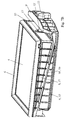
- FIG. 6 is an exploded perspective view of an air-filter device according to a practical embodiment of the invention, in relation to the second embodiment, and,
- FIGS. 7A and 7B are perspective views of the assembly [supporting body+compression body+filtering body+control device] forming part of the device shown in FIG. 6 , in the released position ( FIG. 7A ) and in the forced stress position ( FIG. 7B ) respectively of the compression body.
- the air-filter device 1 basically comprises, on the one hand, a casing 2 , in one or more parts 2 ′, defining a volume or so-called clean compartment 3 receiving the filtered gases and a volume or so-called dirty compartment 3 ′ receiving the gases to be filtered and, on the other hand, a filtering body 4 separating the two above-mentioned compartments, installed in an intermediate mounting area or compartment 5 and having a peripheral seal 6 that comes to be applied against an edge or circumferential similar internal step 7 of the casing 2 , which delimits the said intermediate compartment 5 in relation to the clean compartment 3 .
- the said device 1 also comprises a supporting body 8 that locks or wedges up, possibly with lateral retaining means, the filtering body 4 in the mounted condition and a compression body 9 designed to co-operate mechanically with the supporting body 8 at the respective contact surfaces 10 and 10 ′ coming to bear in mutual sliding, the two above-mentioned bodies 8 and 9 having structures in the form of frames and being mounted in the manner of drawers sliding in the intermediate compartment 5 , the latter having a side access opening 11 made in the casing 2 to introduce and extract the filtering body 4 /supporting body 8 assembly, as well as any compression body 9 , by sliding in respective opposite directions D and D′.
- the compression body 9 is also guided in sliding bearing along a second edge or similar circumferential internal step 12 of the casing 2 , delimiting the said intermediate compartment 5 in relation to the dirty compartment 3 ′, and may be moved selectively between a slackening off or release position or range of slackening off or release positions in which the seal 6 of the filtering body 4 is not compressed and a position of forced stress in which the filtering body 4 is locked in position and its seal 6 compressed, under the action of a control device that can be maneuvered from outside the casing 2 and connected or built into a cover or cap 14 designed to block off the side access opening 11 .
- the respective inclinations of the contact surfaces in mutual sliding bearing 10 and 10 ′ of the supporting and compression bodies 8 and 9 are defined so that the forced stress position is achieved by moving the compression body 9 in the extraction direction D′ and so that the control device 13 stresses the supporting body 8 and/or the casing 2 to achieve the movement of the compression body 9 into the forced stress position, at least at the end of the movement.
- the movement of the control device 13 and the resultant movement of the compression body 9 are of a limited extent, preferably with a demultiplication such as to reduce the effort necessary to manoeuvre the said device, even in the event of resistance to sliding by the compression body 9 (for example due to friction, fouling or other causes).
- the extent of the compression movement of the filtering body 4 caused by the body 9 may be within 1 ⁇ 5 th and 1/10 th of the extent of the movement of translation of the said body 9 in direction D′ (for example: 3 mm-21 mm).
- the control device 13 consists of the cover itself 14 , the latter being made in the form of a pivoting cover, and connected to the compression body 9 by a pivot connection 16 so that lowering the said cover 14 towards its position of blocking the side access opening 11 causes a sliding of the compression body 9 towards the stress position, the said pivoting cover 14 being lockable in the blocking position.
- the passage freed up by the cover 14 in the open position will be sufficient to enable the extraction of the supporting body 8 /filtering body 4 assembly, without the need to extract the compression body 9 as well.
- the said cover 14 is also fitted with a seal or a plurality of portions of a seal 14 ′′ making it possible to seal off the access opening 11 when the said cover 14 is in the closed position. In this position, it is also locked by locking means 14 ′′′ or removable means of connection, such as screws, nuts, clamps, lugs or resilient clips or suchlike.
- the pivoting cover 14 can be fitted pivoting on the casing 2 , at the side access opening 11 , so as to form a lever, the said cover 14 preferably having a stop on its inner face to lock the supporting body 8 in the mounted position.
- the cover 14 may come to bear, at least at the end of the lowering movement in the blocking position, on the supporting body 8 , preferably at a stop area 17 of a part 17 ′ of the frame of the supporting body 8 near the side access opening 11 , thus creating a lever stressing the supporting body 8 and the compression body 9 in an opposing manner.
- the cover 14 may also be pivoted only on the compression body 9 , which is then moved to the forced stress position by bringing the said cover 14 into the blocking position against the wall of the casing 2 (effort can be taken up around the access opening 11 ).
- the control device 13 may consist of a traction device connected to the compression body 9 , the said device 13 bearing on the cover 14 , on the supporting body 8 and/or on the casing 2 , at least at the end of the movement of the compression body 9 in the forced stress position.
- the device 13 when the device 13 bears on the cover 14 , and for example passes through the latter, it will also contribute to holding in place and achieving the seal at the opening 11 (compression of the cover seal 14 ′′.
- control device 13 may also be built into the cover 14 , forming a distinctive part of the said cover ( FIG. 3B ).
- the control device 13 may also be located beneath the cover or cap 14 , being covered by the latter ( FIGS. 6 and 7 ).
- control device 13 may be maneuvered progressively, for example by rotation, or by tilting, passing through a point of resistance.
- the device 13 may for example consist of a rotating knob with a threaded shank 13 ′ engaging in a threaded orifice 9 ′′ of a part in the form of a wing 9 ′ of the frame of the compression body 9 , in the manner of a nut/screw assembly, it being possible for the free end of the said threaded shank 13 ′ to bear on the supporting body 8 (end-stop area 17 ).
- a rotation of the rotating knob 13 will cause a sliding in translation of the compression body 9 .
- the control device 13 also locks the supporting body 8 in the mounted position, for example by coming to bear at an end-stop area 17 of a part 17 ′ of the frame of the supporting body 8 near the side access opening 11 .
- the opposite side parts 15 , 15 ′ of the frames forming the supporting body 8 and compression body 9 which extend in the opposite directions of sliding D, D′ of the said bodies, have the form of portions of wall with a wedge profile arranged head to foot. Furthermore, the mutual contact surfaces 10 , 10 ′ of the supporting 8 and compression bodies 9 , as well as the contact surfaces 18 of the compression body 9 guided in sliding bearing along the second edge or step 12 in both sliding directions D, D′, are then provided by the side wings 19 , 20 , 20 ′ of the above-mentioned sides or opposite side parts 15 , 15 ′ of the said frames.
- edges or steps 7 and 12 are advantageously formed in a recess towards the outside of the wall of the casing 2 corresponding with the intermediate compartment 5 , so as to be located outside the common passage section of the casing 2 at this level and also to enable the bodies 8 and 9 to be positioned substantially outside the flow crossing the operational part of the filtering body 4 .
- the thickness of the filtering body 4 generally in the form of a plate or parallelepiped block, is less than the cumulative widths of the wall portions of parts 15 and 15 ′, the volume of the dirty compartment 3 ′ extends into the internal spaces of the frames of the said bodies 8 and 9 .
- the filtering body 4 is at least partially received and held encompassed in the frame of the supporting body 8 , the latter having a circumferential edge 21 receiving the peripheral seal 6 and ensuring its compression and side holding against the corresponding edge or step 7 of the casing 2 , possibly simultaneously constituting a maximum compression end-stop ( FIG. 5B ).
- the filtering body 4 may, depending on its nature and type, have a seal 6 inserted by gluing or moulding a suitable material, or have a seal 6 made integral with the filtering body 4 , for example in the form of a band of peripheral material, possibly adapted for this purpose by shaping, forming or special treatment of its constituent material.
- each edge 12 may, in a variant, be in the form of a runner inside which slides a wing 20 ′ of the compression body 9 having a contact surface or surfaces 18 .
- the side parts 15 ′ of the compression body may have, at their wings 20 , a side edge or side edge portions 20 ′′assuring the side guidance of the supporting body 8 on the compression body 9 at their contact surfaces 10 and 10 ′ bearing in mutual sliding bearing.
- the provision of a receiving recess in the wall of the casing 2 is no longer necessary.
- the intermediate compartment 5 has an end-stop 22 to lock or stop the supporting body 8 in the direction of insertion D and the filtering body 4 has an end-stop 23 locking the supporting body 8 in the direction of extraction D′, the supporting body 8 and compression body 9 possibly being connected by an end-of-travel drive link 24 , notably in the direction of extraction D′.
- the supporting body 8 and the filtering body 4 may form a single body, obtained by manufacturing them in one piece, possibly in a plurality of successive stages, or by assembly, for example by gluing or welding.
- the present invention also relates to an air inlet assembly for a vehicle with an internal combustion engine, characterised in that it comprises at least one air-filter device 1 such as that described above.
Landscapes
- Engineering & Computer Science (AREA)
- Chemical & Material Sciences (AREA)
- Mechanical Engineering (AREA)
- Chemical Kinetics & Catalysis (AREA)
- Manufacturing & Machinery (AREA)
- Combustion & Propulsion (AREA)
- General Engineering & Computer Science (AREA)
- Filtering Of Dispersed Particles In Gases (AREA)
- Compressor (AREA)
Applications Claiming Priority (2)
| Application Number | Priority Date | Filing Date | Title |
|---|---|---|---|
| FR0654761A FR2908159B1 (fr) | 2006-11-07 | 2006-11-07 | Dispositif de filtre a air a tiroir et ensemble d'admission comprenant un tel dispositif |
| FR0654761 | 2006-11-07 |
Publications (2)
| Publication Number | Publication Date |
|---|---|
| US20080110146A1 US20080110146A1 (en) | 2008-05-15 |
| US7771502B2 true US7771502B2 (en) | 2010-08-10 |
Family
ID=38068817
Family Applications (1)
| Application Number | Title | Priority Date | Filing Date |
|---|---|---|---|
| US11/936,466 Active 2028-10-13 US7771502B2 (en) | 2006-11-07 | 2007-11-07 | Drawer air-filter device and inlet assembly having such a device |
Country Status (5)
| Country | Link |
|---|---|
| US (1) | US7771502B2 (de) |
| EP (1) | EP1920816B1 (de) |
| AT (1) | ATE474648T1 (de) |
| DE (1) | DE602007007870D1 (de) |
| FR (1) | FR2908159B1 (de) |
Cited By (4)
| Publication number | Priority date | Publication date | Assignee | Title |
|---|---|---|---|---|
| US20100139225A1 (en) * | 2006-12-08 | 2010-06-10 | John Ronald Mammarella | Filter housing and production method |
| US20150285195A1 (en) * | 2014-04-08 | 2015-10-08 | Hyundai Motor Company | Air cleaner apparatus for vehicle and mold unit for fabricating the same |
| USD796661S1 (en) * | 2013-03-01 | 2017-09-05 | Michael E. Oswald, Jr. | Vent cover with frame |
| US20220195970A1 (en) * | 2020-12-17 | 2022-06-23 | Ford Global Technologies, Llc | Methods and systems for an airbox |
Families Citing this family (34)
| Publication number | Priority date | Publication date | Assignee | Title |
|---|---|---|---|---|
| KR20050098922A (ko) | 2003-02-11 | 2005-10-12 | 도널드선 컴파니 인코포레이티드 | 에어 크리너 배열과 서비스가능한 필터 구성 요소 및 방법 |
| US7799108B2 (en) * | 2005-12-16 | 2010-09-21 | Cummins Filtration Ip, Inc. | Volume-efficient filter |
| US7540895B2 (en) * | 2005-12-16 | 2009-06-02 | Fleetguard, Inc. | Multiple flow filter system |
| JP4697158B2 (ja) * | 2007-03-08 | 2011-06-08 | トヨタ紡織株式会社 | エアクリーナ |
| KR101189235B1 (ko) * | 2010-09-28 | 2012-10-09 | 현대자동차주식회사 | 차량용 에어 클리너 |
| US8394159B2 (en) * | 2011-01-31 | 2013-03-12 | Honda Motor Co., Ltd. | Vehicle air cleaner housing |
| KR101354276B1 (ko) | 2011-12-02 | 2014-01-24 | 기아자동차주식회사 | 차량용 에어클리너 |
| JP5998993B2 (ja) * | 2013-03-13 | 2016-09-28 | トヨタ紡織株式会社 | エアクリーナ |
| KR101318188B1 (ko) * | 2013-07-02 | 2013-10-16 | 주식회사 리한 | 차량용 에어클리너 |
| US9169811B2 (en) * | 2013-08-06 | 2015-10-27 | Kia Motors Corporation | Air cleaner for vehicle |
| KR101449321B1 (ko) | 2013-08-20 | 2014-10-08 | 주식회사 리한 | 차량용 에어클리너 |
| DE102014012490A1 (de) | 2014-08-27 | 2016-03-03 | Mann + Hummel Gmbh | Filterelement mit schräger Dichtungsebene |
| DE102014015760B4 (de) * | 2014-10-27 | 2016-07-14 | Mann + Hummel Gmbh | Filtergehäuse mit Hebelelement |
| DE102014224549B4 (de) * | 2014-12-01 | 2026-04-30 | Mahle International Gmbh | Plattenförmiges Filterelement sowie Filtereinrichtung und Verwendung eines Filtergehäuses |
| US9567949B2 (en) * | 2015-01-09 | 2017-02-14 | Mann+Hummel Gmbh | Air cleaner in particular of an internal combustion engine |
| US11591993B2 (en) * | 2015-02-09 | 2023-02-28 | Mann+Hummel Gmbh | Filter element and air cleaner assembly |
| JP2017096207A (ja) * | 2015-11-26 | 2017-06-01 | 和興フィルタテクノロジー株式会社 | エアクリーナ、及び、エアクリーナの製造方法 |
| JP5945624B1 (ja) * | 2015-11-26 | 2016-07-05 | 和興フィルタテクノロジー株式会社 | エアクリーナ |
| AU2016259419B2 (en) * | 2015-11-30 | 2020-12-10 | Parker-Hannifin Corporation | Engine Panel Filter and Housing System |
| JP6582955B2 (ja) * | 2015-12-14 | 2019-10-02 | トヨタ紡織株式会社 | エアクリーナ |
| KR101734734B1 (ko) * | 2015-12-31 | 2017-05-11 | 현대자동차주식회사 | 정비 편의성을 증대한 서랍식 에어클리너와 흡기시스템 및 차량 |
| DE102016001132A1 (de) | 2016-02-03 | 2017-08-03 | Mann + Hummel Gmbh | Filterelement, Elementrahmen eines Filterelements, Filterbalg eines Filterelements, Filtergehäuse und Filter |
| DE102016001134A1 (de) * | 2016-02-03 | 2017-08-03 | Mann + Hummel Gmbh | Filtergehäuse und Filter |
| EP3228376B1 (de) * | 2016-04-08 | 2019-11-27 | Mann+Hummel GmbH | Filtermodul mit einem filterelement und einem befestigungsrahmen und luftfilteranlage mit einem filtermodul |
| CN106286032B (zh) * | 2016-09-23 | 2018-05-11 | 瑞安市荣际汽车零部件有限公司 | 一种发动机用空气滤清器 |
| DE102017007498A1 (de) * | 2017-08-08 | 2019-02-14 | Daimler Ag | Filterelement für einen Luftfilter eines Kraftwagens und Luftfilter |
| FR3073902A1 (fr) * | 2017-11-17 | 2019-05-24 | Psa Automobiles Sa | Filtre a air avec un receptacle |
| KR102586915B1 (ko) * | 2018-06-08 | 2023-10-10 | 현대자동차주식회사 | 자동차용 서랍식 에어클리너 필터 커버 구조, 에어클리너, 흡기시스템 및 이를 포함하는 차량 |
| US12196431B2 (en) * | 2019-12-10 | 2025-01-14 | Lg Electronics Inc. | Air management apparatus or device |
| CN111305982A (zh) * | 2020-04-15 | 2020-06-19 | 上海弗列加滤清器有限公司 | 一种空气滤清器 |
| JP7723517B2 (ja) * | 2021-07-19 | 2025-08-14 | 株式会社Subaru | 気体濾過装置 |
| US12491460B2 (en) * | 2021-09-30 | 2025-12-09 | Carrier Corporation | Duct mounted filtering apparatus |
| CN114294134B (zh) * | 2022-03-11 | 2022-05-13 | 氢山(北京)氢内燃机技术研究院有限公司 | 用于车辆氢内燃机的进气系统 |
| DE102022119072A1 (de) | 2022-07-29 | 2024-02-01 | Mann+Hummel Gmbh | Luftfilter |
Citations (12)
| Publication number | Priority date | Publication date | Assignee | Title |
|---|---|---|---|---|
| EP0391019A1 (de) | 1989-04-06 | 1990-10-10 | FILTERWERK MANN & HUMMEL GMBH | Ansaugluftfilter für Brennkraftmaschinen |
| US5740774A (en) | 1996-12-18 | 1998-04-21 | Siemens Electric Limited | Engine induction air system having improved air filter accessibility |
| US6217627B1 (en) * | 1999-06-29 | 2001-04-17 | Siemens Canada Limited | Cam operated drawer style air cleaner |
| US6422197B1 (en) * | 1999-10-29 | 2002-07-23 | Filterwerk Mann & Hummel Gmbh | Intake system |
| US6440189B1 (en) * | 1999-03-30 | 2002-08-27 | Denso Corporation | Air conditioning apparatus with detachable filter |
| US6623350B2 (en) * | 2002-02-19 | 2003-09-23 | Delphi Technologies, Inc. | Motor vehicle air filter apparatus with an easily removable air filter |
| US20040020177A1 (en) | 2002-07-31 | 2004-02-05 | Toyo Roki Seizo Kabushiki Kaisha | Air cleaner |
| US6878176B2 (en) * | 2001-10-26 | 2005-04-12 | Agco, S.A. | Air conditioning filter |
| WO2005079954A1 (en) | 2004-02-17 | 2005-09-01 | Donaldson Company, Inc. | Air cleaner arrangements; serviceable filter elements; and, methods |
| WO2006009766A1 (en) | 2004-06-18 | 2006-01-26 | Donaldson Company, Inc. | Air cleaner arrangements; serviceable filter cartridge; and, methods |
| US7128643B2 (en) * | 2004-06-01 | 2006-10-31 | Aci Air Technologies, Llc | Removable vent having a filter for use in a building foundation |
| US7323029B2 (en) * | 2003-02-11 | 2008-01-29 | Donaldson Company, Inc. | Air cleaner arrangements; serviceable filter elements; and, methods |
-
2006
- 2006-11-07 FR FR0654761A patent/FR2908159B1/fr not_active Expired - Fee Related
-
2007
- 2007-11-07 EP EP07120189A patent/EP1920816B1/de not_active Ceased
- 2007-11-07 DE DE602007007870T patent/DE602007007870D1/de active Active
- 2007-11-07 AT AT07120189T patent/ATE474648T1/de not_active IP Right Cessation
- 2007-11-07 US US11/936,466 patent/US7771502B2/en active Active
Patent Citations (13)
| Publication number | Priority date | Publication date | Assignee | Title |
|---|---|---|---|---|
| EP0391019A1 (de) | 1989-04-06 | 1990-10-10 | FILTERWERK MANN & HUMMEL GMBH | Ansaugluftfilter für Brennkraftmaschinen |
| US5740774A (en) | 1996-12-18 | 1998-04-21 | Siemens Electric Limited | Engine induction air system having improved air filter accessibility |
| US6440189B1 (en) * | 1999-03-30 | 2002-08-27 | Denso Corporation | Air conditioning apparatus with detachable filter |
| US6217627B1 (en) * | 1999-06-29 | 2001-04-17 | Siemens Canada Limited | Cam operated drawer style air cleaner |
| US6422197B1 (en) * | 1999-10-29 | 2002-07-23 | Filterwerk Mann & Hummel Gmbh | Intake system |
| US6878176B2 (en) * | 2001-10-26 | 2005-04-12 | Agco, S.A. | Air conditioning filter |
| US6623350B2 (en) * | 2002-02-19 | 2003-09-23 | Delphi Technologies, Inc. | Motor vehicle air filter apparatus with an easily removable air filter |
| US20040020177A1 (en) | 2002-07-31 | 2004-02-05 | Toyo Roki Seizo Kabushiki Kaisha | Air cleaner |
| US6808547B2 (en) * | 2002-07-31 | 2004-10-26 | Toyo Roki Seizo Kabushiki Kaisha | Air cleaner |
| US7323029B2 (en) * | 2003-02-11 | 2008-01-29 | Donaldson Company, Inc. | Air cleaner arrangements; serviceable filter elements; and, methods |
| WO2005079954A1 (en) | 2004-02-17 | 2005-09-01 | Donaldson Company, Inc. | Air cleaner arrangements; serviceable filter elements; and, methods |
| US7128643B2 (en) * | 2004-06-01 | 2006-10-31 | Aci Air Technologies, Llc | Removable vent having a filter for use in a building foundation |
| WO2006009766A1 (en) | 2004-06-18 | 2006-01-26 | Donaldson Company, Inc. | Air cleaner arrangements; serviceable filter cartridge; and, methods |
Non-Patent Citations (2)
| Title |
|---|
| European Search Report for European Patent Application No. EP07120798.1, Mailed Feb. 20, 2008, pp. 6 (lists same references as French Search Report). |
| Search Report prepared by Institut National De La Propriete Industrielle on Jun. 5, 2007, for French Patent Application No. FR0654761. |
Cited By (6)
| Publication number | Priority date | Publication date | Assignee | Title |
|---|---|---|---|---|
| US20100139225A1 (en) * | 2006-12-08 | 2010-06-10 | John Ronald Mammarella | Filter housing and production method |
| USD796661S1 (en) * | 2013-03-01 | 2017-09-05 | Michael E. Oswald, Jr. | Vent cover with frame |
| US20150285195A1 (en) * | 2014-04-08 | 2015-10-08 | Hyundai Motor Company | Air cleaner apparatus for vehicle and mold unit for fabricating the same |
| US9599074B2 (en) * | 2014-04-08 | 2017-03-21 | Hyundai Motor Company | Air cleaner apparatus for vehicle and mold unit for fabricating the same |
| US20220195970A1 (en) * | 2020-12-17 | 2022-06-23 | Ford Global Technologies, Llc | Methods and systems for an airbox |
| US11629677B2 (en) * | 2020-12-17 | 2023-04-18 | Ford Global Technologies, Llc | Methods and systems for an airbox |
Also Published As
| Publication number | Publication date |
|---|---|
| EP1920816A1 (de) | 2008-05-14 |
| FR2908159A1 (fr) | 2008-05-09 |
| ATE474648T1 (de) | 2010-08-15 |
| US20080110146A1 (en) | 2008-05-15 |
| FR2908159B1 (fr) | 2009-01-23 |
| EP1920816B1 (de) | 2010-07-21 |
| DE602007007870D1 (de) | 2010-09-02 |
Similar Documents
| Publication | Publication Date | Title |
|---|---|---|
| US7771502B2 (en) | Drawer air-filter device and inlet assembly having such a device | |
| US20040000763A1 (en) | Molded gasket | |
| EP2840215B1 (de) | Anschlagpuffer für Fahrzeugtürschließdämpfung | |
| EP2062761A2 (de) | Klimaanlage für ein Kraftfahrzeug | |
| DE3008972C2 (de) | Notlaufring für Fahrzeug-Luftreifen | |
| KR102028629B1 (ko) | 캠슬라이드 조립체를 구비한 금형 | |
| DE4423370A1 (de) | Drosselklappen-Stutzen für eine Brennkraftmaschine | |
| DE69725520T2 (de) | Kraftstofftank-Verschluss mit Schloss und Verfahren zum Verpacken desselben | |
| US20250163741A1 (en) | Device for closing off an opening made in the body of a vehicle, and corresponding vehicle | |
| KR20220148290A (ko) | 자동차의 에어 필터 장치용 필터 엘리먼트 및 에어 필터 장치 | |
| WO2022184338A1 (de) | Fensterscheibenanordnung für ein fahrzeug | |
| EP1264720A3 (de) | Schiebedachanordnung | |
| EP2766605A1 (de) | Zylinderkopf für einen kompressor | |
| EP1518754A2 (de) | Äussere Lichtanzeige für eine dritte Bremsleuchte für Kraftfahrzeuge | |
| DE20311653U1 (de) | Dichtungseinrichtung an einer Schwenkschiebetür für Fahrzeuge zur Personenbeförderung, insbesondere Schienenfahrzeuge | |
| EP0449372A2 (de) | Fahrzeugkippfenster mit einem Federsystem zur festen Einstellung der geöffneten und geschlossenen Stellung des beweglichen Fensters | |
| EP2268181B1 (de) | Staubsauger mit unterdruckventil | |
| KR20200042726A (ko) | 차량용 오일필터 체결기구 | |
| KR20030092229A (ko) | 자동차용 도어체커장치 | |
| KR20020038311A (ko) | 자동차용 에어크리너 | |
| DE4425460C2 (de) | Betriebsüberwachungsanordnung für Schleifstücke von Stromabnehmern | |
| US20130056408A1 (en) | Fuel filter device | |
| DE102004040985A1 (de) | Staubsauger mit angeformtem Ventilgehäuse | |
| DE19512643C1 (de) | Vorrichtung zur Entlüftung des Kurbelgehäuses einer Brennkraftmaschine | |
| EP4552956A1 (de) | Dachanordnung für strassenfahrzeug und strassenfahrzeug mit solch einer dachanordnung |
Legal Events
| Date | Code | Title | Description |
|---|---|---|---|
| AS | Assignment |
Owner name: MARK IV SYSTEMES MOTEURS (SAS), FRANCE Free format text: ASSIGNMENT OF ASSIGNORS INTEREST;ASSIGNORS:GERMAIN, LAURENT;COTTET, FRANCOIS;WINKELMULLER, HUGUES;REEL/FRAME:020459/0409 Effective date: 20080124 |
|
| STCF | Information on status: patent grant |
Free format text: PATENTED CASE |
|
| FPAY | Fee payment |
Year of fee payment: 4 |
|
| MAFP | Maintenance fee payment |
Free format text: PAYMENT OF MAINTENANCE FEE, 8TH YEAR, LARGE ENTITY (ORIGINAL EVENT CODE: M1552) Year of fee payment: 8 |
|
| MAFP | Maintenance fee payment |
Free format text: PAYMENT OF MAINTENANCE FEE, 12TH YEAR, LARGE ENTITY (ORIGINAL EVENT CODE: M1553); ENTITY STATUS OF PATENT OWNER: LARGE ENTITY Year of fee payment: 12 |