US7775105B2 - Multi-function sensor - Google Patents
Multi-function sensor Download PDFInfo
- Publication number
- US7775105B2 US7775105B2 US11/587,325 US58732505A US7775105B2 US 7775105 B2 US7775105 B2 US 7775105B2 US 58732505 A US58732505 A US 58732505A US 7775105 B2 US7775105 B2 US 7775105B2
- Authority
- US
- United States
- Prior art keywords
- sensor module
- sensor
- turbidity
- function
- fluid
- Prior art date
- Legal status (The legal status is an assumption and is not a legal conclusion. Google has not performed a legal analysis and makes no representation as to the accuracy of the status listed.)
- Expired - Fee Related, expires
Links
- 239000012530 fluid Substances 0.000 claims abstract description 112
- 239000007788 liquid Substances 0.000 claims abstract description 57
- 239000000758 substrate Substances 0.000 claims description 22
- 238000001514 detection method Methods 0.000 claims description 17
- 238000000576 coating method Methods 0.000 claims description 10
- 238000010438 heat treatment Methods 0.000 claims description 10
- 230000003287 optical effect Effects 0.000 claims description 9
- 239000011248 coating agent Substances 0.000 claims description 8
- 239000000919 ceramic Substances 0.000 claims description 7
- 230000008859 change Effects 0.000 claims description 6
- 230000001419 dependent effect Effects 0.000 claims description 4
- 230000004044 response Effects 0.000 claims description 4
- 229920001940 conductive polymer Polymers 0.000 claims description 3
- OKTJSMMVPCPJKN-UHFFFAOYSA-N Carbon Chemical compound [C] OKTJSMMVPCPJKN-UHFFFAOYSA-N 0.000 claims description 2
- 229910052799 carbon Inorganic materials 0.000 claims description 2
- 229920000052 poly(p-xylylene) Polymers 0.000 claims description 2
- 238000012544 monitoring process Methods 0.000 abstract description 5
- 238000010586 diagram Methods 0.000 description 14
- 239000000463 material Substances 0.000 description 13
- 230000003750 conditioning effect Effects 0.000 description 9
- 230000008901 benefit Effects 0.000 description 6
- 230000001681 protective effect Effects 0.000 description 6
- 239000000523 sample Substances 0.000 description 6
- 230000001105 regulatory effect Effects 0.000 description 5
- 238000012546 transfer Methods 0.000 description 5
- 238000013019 agitation Methods 0.000 description 4
- 230000000875 corresponding effect Effects 0.000 description 4
- 239000013618 particulate matter Substances 0.000 description 4
- 239000004593 Epoxy Substances 0.000 description 3
- 230000003749 cleanliness Effects 0.000 description 3
- 238000005259 measurement Methods 0.000 description 3
- 238000000034 method Methods 0.000 description 3
- 239000004065 semiconductor Substances 0.000 description 3
- XLYOFNOQVPJJNP-UHFFFAOYSA-N water Substances O XLYOFNOQVPJJNP-UHFFFAOYSA-N 0.000 description 3
- 238000003466 welding Methods 0.000 description 3
- 230000007423 decrease Effects 0.000 description 2
- 230000007613 environmental effect Effects 0.000 description 2
- 239000011521 glass Substances 0.000 description 2
- 239000002184 metal Substances 0.000 description 2
- 229910052751 metal Inorganic materials 0.000 description 2
- 230000035515 penetration Effects 0.000 description 2
- 230000001902 propagating effect Effects 0.000 description 2
- 229910000679 solder Inorganic materials 0.000 description 2
- 229920000265 Polyparaphenylene Polymers 0.000 description 1
- XUIMIQQOPSSXEZ-UHFFFAOYSA-N Silicon Chemical compound [Si] XUIMIQQOPSSXEZ-UHFFFAOYSA-N 0.000 description 1
- 238000005299 abrasion Methods 0.000 description 1
- 239000000654 additive Substances 0.000 description 1
- 230000000996 additive effect Effects 0.000 description 1
- HSFWRNGVRCDJHI-UHFFFAOYSA-N alpha-acetylene Natural products C#C HSFWRNGVRCDJHI-UHFFFAOYSA-N 0.000 description 1
- 230000003466 anti-cipated effect Effects 0.000 description 1
- 238000013459 approach Methods 0.000 description 1
- 230000004888 barrier function Effects 0.000 description 1
- 229920005601 base polymer Polymers 0.000 description 1
- 238000005219 brazing Methods 0.000 description 1
- 230000015556 catabolic process Effects 0.000 description 1
- 238000002485 combustion reaction Methods 0.000 description 1
- 238000012937 correction Methods 0.000 description 1
- 230000002596 correlated effect Effects 0.000 description 1
- 230000003247 decreasing effect Effects 0.000 description 1
- 238000006731 degradation reaction Methods 0.000 description 1
- 238000013461 design Methods 0.000 description 1
- 238000010292 electrical insulation Methods 0.000 description 1
- 238000005516 engineering process Methods 0.000 description 1
- 239000000945 filler Substances 0.000 description 1
- 239000002828 fuel tank Substances 0.000 description 1
- 230000017525 heat dissipation Effects 0.000 description 1
- 238000007654 immersion Methods 0.000 description 1
- 230000001771 impaired effect Effects 0.000 description 1
- 238000010348 incorporation Methods 0.000 description 1
- 238000009434 installation Methods 0.000 description 1
- 230000003993 interaction Effects 0.000 description 1
- 238000012423 maintenance Methods 0.000 description 1
- 238000004519 manufacturing process Methods 0.000 description 1
- 150000002739 metals Chemical class 0.000 description 1
- 239000000203 mixture Substances 0.000 description 1
- 238000012986 modification Methods 0.000 description 1
- 230000004048 modification Effects 0.000 description 1
- 230000000737 periodic effect Effects 0.000 description 1
- 229920001197 polyacetylene Polymers 0.000 description 1
- 229920000767 polyaniline Polymers 0.000 description 1
- 229920000642 polymer Polymers 0.000 description 1
- -1 polyparaphenylene Polymers 0.000 description 1
- 229920000128 polypyrrole Polymers 0.000 description 1
- 229920000915 polyvinyl chloride Polymers 0.000 description 1
- 239000004800 polyvinyl chloride Substances 0.000 description 1
- 238000012545 processing Methods 0.000 description 1
- 230000002035 prolonged effect Effects 0.000 description 1
- 230000004043 responsiveness Effects 0.000 description 1
- 230000035945 sensitivity Effects 0.000 description 1
- 229910052710 silicon Inorganic materials 0.000 description 1
- 239000010703 silicon Substances 0.000 description 1
- 230000001052 transient effect Effects 0.000 description 1
- 238000011144 upstream manufacturing Methods 0.000 description 1
Images


Classifications
-
- G—PHYSICS
- G01—MEASURING; TESTING
- G01F—MEASURING VOLUME, VOLUME FLOW, MASS FLOW OR LIQUID LEVEL; METERING BY VOLUME
- G01F23/00—Indicating or measuring liquid level or level of fluent solid material, e.g. indicating in terms of volume or indicating by means of an alarm
- G01F23/22—Indicating or measuring liquid level or level of fluent solid material, e.g. indicating in terms of volume or indicating by means of an alarm by measuring physical variables, other than linear dimensions, pressure or weight, dependent on the level to be measured, e.g. by difference of heat transfer of steam or water
- G01F23/24—Indicating or measuring liquid level or level of fluent solid material, e.g. indicating in terms of volume or indicating by means of an alarm by measuring physical variables, other than linear dimensions, pressure or weight, dependent on the level to be measured, e.g. by difference of heat transfer of steam or water by measuring variations of resistance of resistors due to contact with conductor fluid
- G01F23/246—Indicating or measuring liquid level or level of fluent solid material, e.g. indicating in terms of volume or indicating by means of an alarm by measuring physical variables, other than linear dimensions, pressure or weight, dependent on the level to be measured, e.g. by difference of heat transfer of steam or water by measuring variations of resistance of resistors due to contact with conductor fluid thermal devices
- G01F23/247—Indicating or measuring liquid level or level of fluent solid material, e.g. indicating in terms of volume or indicating by means of an alarm by measuring physical variables, other than linear dimensions, pressure or weight, dependent on the level to be measured, e.g. by difference of heat transfer of steam or water by measuring variations of resistance of resistors due to contact with conductor fluid thermal devices for discrete levels
-
- G—PHYSICS
- G01—MEASURING; TESTING
- G01F—MEASURING VOLUME, VOLUME FLOW, MASS FLOW OR LIQUID LEVEL; METERING BY VOLUME
- G01F1/00—Measuring the volume flow or mass flow of fluid or fluent solid material wherein the fluid passes through a meter in a continuous flow
- G01F1/68—Measuring the volume flow or mass flow of fluid or fluent solid material wherein the fluid passes through a meter in a continuous flow by using thermal effects
- G01F1/696—Circuits therefor, e.g. constant-current flow meters
-
- G—PHYSICS
- G01—MEASURING; TESTING
- G01F—MEASURING VOLUME, VOLUME FLOW, MASS FLOW OR LIQUID LEVEL; METERING BY VOLUME
- G01F23/00—Indicating or measuring liquid level or level of fluent solid material, e.g. indicating in terms of volume or indicating by means of an alarm
- G01F23/22—Indicating or measuring liquid level or level of fluent solid material, e.g. indicating in terms of volume or indicating by means of an alarm by measuring physical variables, other than linear dimensions, pressure or weight, dependent on the level to be measured, e.g. by difference of heat transfer of steam or water
- G01F23/24—Indicating or measuring liquid level or level of fluent solid material, e.g. indicating in terms of volume or indicating by means of an alarm by measuring physical variables, other than linear dimensions, pressure or weight, dependent on the level to be measured, e.g. by difference of heat transfer of steam or water by measuring variations of resistance of resistors due to contact with conductor fluid
- G01F23/246—Indicating or measuring liquid level or level of fluent solid material, e.g. indicating in terms of volume or indicating by means of an alarm by measuring physical variables, other than linear dimensions, pressure or weight, dependent on the level to be measured, e.g. by difference of heat transfer of steam or water by measuring variations of resistance of resistors due to contact with conductor fluid thermal devices
- G01F23/247—Indicating or measuring liquid level or level of fluent solid material, e.g. indicating in terms of volume or indicating by means of an alarm by measuring physical variables, other than linear dimensions, pressure or weight, dependent on the level to be measured, e.g. by difference of heat transfer of steam or water by measuring variations of resistance of resistors due to contact with conductor fluid thermal devices for discrete levels
- G01F23/248—Constructional details; Mounting of probes
Definitions
- the invention relates generally to devices used to measure certain ambient conditions within an environment, such as the level or flow rate of a fluid or within a vessel or container, the turbidity of the fluid, and the temperature or pressure of the fluid and/or the ambient environment.
- the multi-function sensor be capable of providing a reliable, accurate indication of the fluid level, fluid flow rate, turbidity, temperature and/or pressure over an extended period of time without requiring periodic maintenance.
- the sensor In many applications the sensor must be capable of enduring various degrees of vibration, heat or other hostile environmental elements, as well as space limitations.
- sealed vessels such as hermetic compressors and household appliances, it is desirable to minimize the number of penetrations through the wall(s) of the vessel in order to reduce the potential for leakage.
- the invention provides an extremely reliable multi-function sensor which is compact and simple in design and can be manufactured at very low costs. Further the sensor of the invention can be encapsulated or coated with a variety of suitable materials to enable it to maintain prolonged operation in numerous different and potentially hostile ambient environments.
- the multi-function sensor of the invention incorporates a combination of more than one of a fluid level sensing component or a fluid flow rate sensing component, a turbidity sensing component, a temperature sensing component and a pressure sensing component.
- the fluid level sensing component comprises a module having at least one first thermocouple junction(s) arranged along a substrate with a suitable heater arranged in close proximity.
- a second, compensating thermocouple junction is associated with each of the at least one first thermocouple junction(s) and laterally spaced therefrom.
- the first and second thermocouple junctions are interconnected in series with respective first and second thermocouple junctions alternating in the serial interconnection.
- the first one(s) of the thermocouple junction(s) provide an indication of a rate of heat dissipation which is directly related to the level of the fluid in which the component is placed, while the second thermocouple junction(s) provide a compensation factor dependent upon the ambient temperature.
- the fluid flow rate sensing component comprises a probe having a detection module adapted to change condition in response to the flow of the fluid, and a control module that is electrically connected to the probe that monitors the condition of the detection module over time (e.g., a temperature), determines a rate of change of that condition over time, and generates an output that is indicative of the rate of flow of the fluid.
- a control module that is electrically connected to the probe that monitors the condition of the detection module over time (e.g., a temperature), determines a rate of change of that condition over time, and generates an output that is indicative of the rate of flow of the fluid.
- the turbidity sensing component comprises a module for measuring the state of cleanliness (or conversely “dirtying”) of a fluid.
- a turbidity measurement is often used to indirectly determine the state of cleanliness of a product to be cleaned, such as within a household appliance like a clothes washer or dishwasher.
- the turbidity sensing component utilizes a light beam propagating through a fluid medium to determine, for example, whether the fluid is clouded by particulate matter suspended in the fluid. The extent to which the light is transmitted, reflected or “scattered” through the medium, correlates and may be calibrated to measure the turbidity of the fluid.
- temperature and pressure sensing components of the multi-function sensor comprise respective modules having thermocouple junctions for providing signals indicative of these conditions in their ambient environments.
- the arrangement of the multi-function sensor of the invention not only provides a very simple and reliable device for obtaining measurements for multiple ambient conditions in an environment, but also further minimizes the number of mounting locations on a container and the corresponding penetrations extending through the container wall. This feature is significant, particularly when the sensor is to be employed within a closed or sealed system.
- a hermetic interface is further provided for use together with the multi-function sensor.
- the hermetic interface enables the sensor to be employed in apparatus having a sealed or closed container into which the multi-function sensor extends through a container wall, such as in a hermetically-sealed compressor or an appliance like a clothes washer or dishwasher.
- the hermetic interface can include a hermetic or semi-hermetic feedthrough that provides one or more pin connectors or leads for electrically connecting to the sensor.
- the hermetic interface enables power from outside of the container to be provided to the multi-function sensor inside of the container and output from the sensor inside the container to pass from to the outside of the container, while not compromising the container's seal.
- the hermetic interface can further include circuitry to regulate the power carried to the multi-function sensor, as well as circuitry for conditioning the sensor's output signal(s).
- a protective shield can be provided to surround the sensor.
- the shield serves as a barrier between the sensor and sloshing fluid disposed within the container.
- FIG. 1 is schematic block diagram of a multi-function sensor in accordance with the invention
- FIG. 2 is a schematic circuit diagram of an exemplary liquid level sensor module of the multi-function sensor of the invention
- FIG. 3 is a schematic circuit diagram of an exemplary reflective-mode turbidity sensor module of the multi-function sensor of the invention.
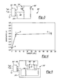
- FIG. 4 is a graph illustrating the output of the reflective-mode turbidity sensor module of FIG. 3 for three exemplary turbidity levels
- FIG. 5 is a schematic circuit diagram of an exemplary transmissive-mode turbidity sensor module of the multi-function sensor of the invention.
- FIG. 6 is a graph illustrating the output of the transmissive-mode turbidity sensor module of FIG. 5 for three exemplary turbidity levels
- FIG. 7 is a schematic circuit diagram of an exemplary pressure sensor module of the multi-function sensor of the invention.
- FIG. 8 is a schematic circuit diagram of an exemplary temperature sensor module of the multi-function sensor of the invention.
- FIG. 9 is an exploded perspective view of one embodiment of the multi-function sensor of the invention.
- FIG. 10 is an exploded perspective view of another embodiment of the multi-function sensor of the invention.
- FIG. 11 is a cross-sectional front view of a multi-function sensor of the invention, such as that shown in FIG. 9 or 10 , which is installed through the wall of an appliance;
- FIG. 12 is a cross-sectional front view of a hermetic interface that may be used with the multi-function sensor of the invention.
- FIG. 13 is a cross-sectional front view of the hermetic interface of FIG. 12 and including a multi-function sensor of the invention disposed therein;
- FIG. 14 is a front view of the hermetic interface of FIG. 12 having a first protective shield disposed thereon;
- FIG. 15 is a front view of the hermetic interface of FIG. 12 having a second protective shield disposed thereon;
- FIG. 16 is a front view of the hermetic interface of FIG. 12 having a third protective shield disposed thereon;
- FIG. 17 is a view of a sealed vessel, such as a hermetic compressor, having a multi-function sensor in accordance with the invention installed therein;
- FIG. 18 is a schematic circuit diagram of an exemplary fluid flow rate sensor module of the multi-function sensor of the invention.
- FIG. 19 is a front view, in partial cross-section, of another embodiment of the multi-function sensor of the invention.
- FIG. 20 is an end view of the embodiment of the multi-function sensor of FIG. 19 .
- Multi-function sensor 10 comprises a printed circuit board 12 upon which a plurality of sensor modules 100 or 200 , 300 , 400 , and 500 are supported.
- the sensor modules 100 or 200 , 300 , 400 , and 500 may include a liquid level sensor module 100 , a turbidity sensor module 200 , a pressure sensor module 300 and a temperature sensor module 400 Alternatively to the liquid level sensor 100 , a fluid flow rate sensor module 500 may be incorporated into the multi-function sensor 10 .
- FIG. 1 a schematic block diagram of a multi-function sensor 10 in accordance with the invention.
- Multi-function sensor 10 comprises a printed circuit board 12 upon which a plurality of sensor modules 100 or 200 , 300 , 400 , and 500 are supported.
- the sensor modules 100 or 200 , 300 , 400 , and 500 may include a liquid level sensor module 100 , a turbidity sensor module 200 , a pressure sensor module 300 and a temperature sensor module 400 Alternatively to the liquid level sensor 100 , a fluid flow rate sensor
- FIG. 1 schematically depicts the several sensor modules 100 , 200 , 300 , 400 , 500 in a particular combination, it is understood that any combination of the several sensor modules 100 , 200 , 300 , 400 , 500 may be employed to provide a multi-function sensor in accordance with the invention.
- the printed circuit board 12 includes a relatively rigid, elongate substrate 14 .
- the substrate 14 may be fabricated from a variety of different materials but will preferably be made from a suitable printed circuit board material having good electrical insulating capabilities and preferably resistant to degradation from the environment in which it will be utilized. It is also preferable that the material be relatively thin to promote heat transfer from one surface to the other so as to promote faster response time in the sensor modules 100 , 200 , 300 , 400 , 500 .
- the printed circuit board 12 and sensor modules 100 , 200 , 300 , 400 , 500 are coated or encapsulated with a thin, electrically insulating coating.
- the coating affords protection to the sensor from environmental elements and reduces the possibility of a short circuit.
- Such coatings must have good heat transfer characteristics but yet must also provide sufficient electrical insulation to the components.
- the coating must be translucent at the operating wavelength of the light source that is associated with the turbidity sensor module, as described below. Additionally, it is highly desirable that the coating be able to clearly shed the liquid in the environment which the multi-function sensor 10 is to be used so as to minimize the potential for erroneous readings.
- One such material that is contemplated for this invention is commercially available under the tradename Parylene.
- One of Dow Corning Corporation's RTV elastomeric conformal coatings may provide another source of suitable coating materials.
- the multi-function sensor 10 of the invention can incorporate a liquid level sensor module 100 for sensing the level of a fluid in an environment.
- the liquid level sensor module 100 is supported on the printed circuit board 12 .
- a suitable liquid level sensor module that may be integrated into the multi-function sensor 10 is shown and described in U.S. Pat. No. 6,546,796, entitled “Liquid Level Sensor,” issued Apr. 15, 2003 and owned by Therm-O-Disc, Incorporated, the assignee of the present patent application, the disclosure of which is hereby incorporated by reference.
- U.S. Pat. No. 6,546,796 describes a liquid level sensor utilizing a plurality of thermocouple junctions grouped in pairs and connected in series, with the pairs being spaced along a line generally extending in the direction along which the liquid level may vary.
- a first or “hot” thermocouple junction of each pair of thermocouple junctions is located in relatively close thermal proximity to an electrically powered heater.
- the second or “cold” thermocouple junction of each pair of thermocouple junctions is relatively laterally offset from the first thermocouple junction and the heater along a line extending parallel to the surface of the liquid to be measured.
- thermocouple junctions Any number of pairs of first and second thermocouple junctions may be selected so as to ensure a sufficient number and spacing to cover a desired range of liquid level to be sensed, as well as the degree of resolution desired.
- An output voltage V LL measured across the thermocouple junctions is indicative of the level of the liquid being sensed.
- FIG. 2 illustrates a schematic circuit diagram for an exemplary liquid level sensor module 100 for the multi-function sensor 10 of the invention.
- the liquid level sensor module 100 generally comprises a heater circuit 102 and a thermocouple circuit 104 .
- the heater circuit 102 includes a plurality of discrete heaters 106 , such as resistors.
- the thermocouple circuit 104 comprises a plurality of “hot” 108 and “cold” 110 thermocouple junctions which are connected in series, alternating between hot 108 and cold 110 thermocouple junctions.
- a voltage divider 112 and an amplifier 114 also form part of the thermocouple circuit 104 in the embodiment shown in FIG. 2 .
- a plurality of traces 116 , 118 , 120 lead to a multi-pin connector 122 comprising a plurality of pins, P 1 , P 2 , P 3 .
- Trace 118 terminates at pin P 2 , where a reference voltage V REF is applied to both the heater circuit 102 and the voltage divider circuit 112 .
- Trace 116 is coupled to the output of the amplifier 114 in the thermocouple circuit 104 and terminates at pin P 1 where an output voltage V LL can be read.
- the output voltage V LL is indicative of the liquid level that is sensed by the liquid level sensor module 100 .
- Trace 120 terminates at pin P 3 which is connected to ground.
- the reference voltage V REF applied to the heater circuit 102 raises the temperature of the heaters 106 above the ambient temperature.
- Thermal energy from the heaters 106 is conducted to the hot thermocouple junctions 108 , which are in relatively close proximity to the heaters 106 .
- Each hot thermocouple junction 108 generates a voltage potential when heated, the magnitude of which increases with increases in its temperature.
- the hot thermocouple junctions 108 are connected in series and the voltage potential generated by each hot thermocouple junction 108 is additive to the others.
- the total voltage potential generated when the liquid level sensor module 100 is not immersed in liquid, V NI equals n times the potential generated by a single hot thermocouple junction, where n is the number thermocouple junctions.
- thermocouple junction 108 when a hot thermocouple junction 108 is immersed in a liquid, the liquid's greater thermal transfer efficiency (as opposed to gaseous fluids) reduces the amount that the hot thermocouple junction 108 is heated by the heater 106 . Hence, it generates a lower voltage potential than it would were it not immersed in the liquid. Correspondingly, the total voltage potential for all of the thermocouple junctions is reduced. When the total voltage potential, then, falls below V NI it is indicative of the sensor's presence in a liquid environment. As more of the thermocouple junctions become immersed in the liquid, the total voltage potential continues to decrease until it reaches a value V FI , which is the point at which all of the thermocouples are fully immersed in the fluid.
- thermocouple circuit 104 includes corresponding cold thermocouple junctions 110 for each of the hot thermocouple junctions 108 .
- the cold thermocouple junctions 110 are not located in proximity to the heaters 106 and, therefore, thermal energy from the heaters 106 is not conducted to the cold thermocouple junctions 110 .
- the cold thermocouple junctions 110 remain at ambient temperature.
- each cold thermocouple junction 110 is wired in the thermocouple circuit so as to generate a voltage potential that is of opposite polarity to that of its associated hot thermocouple junction 108 . Because the cold thermocouple junctions 110 are interconnected in an alternating series relationship with the hot thermocouple junctions 108 , their opposite polarity voltage potentials subtract from the voltage potentials that are generated by the hot thermocouple junctions 108 . As one having ordinary skill in the art will appreciate, the summation of the hot and cold thermocouple junctions' 108 , 110 voltage potentials result in the output voltage, V LL , which is not only indicative of the liquid level sensed by sensor module 14 , but also eliminates the ambient temperature's influence on the output.
- the liquid level sensor module 100 example shown schematically in FIG. 2 provides sensing capabilities for four discrete liquid levels (i.e., it has four pairs of hot and cold thermocouple junctions 108 , 110 ).
- the multi-function sensor of the invention may incorporate a liquid level sensor module that simply senses whether a threshold fluid level has been attained.
- One such liquid level sensor is shown and described in U.S. Pat. No. 6,862,932 entitled “Liquid Level Sensor,” issued Mar. 8, 2005 and owned by Therm-O-Disc, Incorporated, the assignee of the present patent application, the disclosure of which is hereby incorporated by reference.
- line 55 through col. 14, line 2 U.S. Pat. No.
- 6,862,932 describes a liquid level sensor operating on the same principles as the liquid level sensor described above, but utilizing only a single pair of thermocouple junctions, one “hot” and one “cold.”
- An output voltage of a first value is associated with the immersion of the sensor in the liquid and indicates that the level of the liquid has reached or exceeded a threshold level.
- An output voltage of a second, higher value indicates that the liquid has fallen below the threshold level.
- a turbidity sensor module 200 for use in the multi-function sensor 10 of the invention is schematically shown and described.
- the turbidity sensor module 200 senses the state of cleanliness (or conversely “dirtying”) of a fluid.
- the turbidity sensor module 200 utilizes a light beam propagating through a fluid to determine, for example, whether the fluid is clouded by particulate matter that is suspended in the fluid. The extent to which the light is transmitted, reflected or scattered through the fluid, correlates to and may be calibrated to measure the relative turbidity of the fluid.
- FIG. 3 shows a schematic circuit diagram of a first embodiment of an exemplary turbidity sensor module 200 ′.
- the turbidity sensor module 200 ′ comprises a reflective mode-type optical sensor.
- the turbidity sensor module 200 ′ incorporates a light source 202 ′, such as a light emitting diode (LED), that propagates a light signal, such as an infra-red light signal for example.
- a photosensor 204 ′ such as a photodiode or phototransistor, is paired with the light source 202 ′ and is arranged electrically in parallel to the light source 202 ′.
- the photosensor 204 ′ is included in the turbidity sensor module 200 ′ to detect the intensity of the light that is reflected by the fluid in which it is disposed.
- the photosensor 204 ′ acts as a variable resistor, decreasing in resistance as the amount of reflected light being detected increases.
- the greater the turbidity the fluid the greater amount of light that is reflected by the fluid and detected by the photosensor 204 ′.
- the higher the turbidity the lower the resistance of the photosensor 204 ′.
- the light source 202 ′ and photosensor 204 ′ components that may be employed in the turbidity sensor module 200 ′ of the invention are well-known and commercially available.
- Components which are suitable for incorporation into the turbidity sensor module 200 ′ include a surface mount LED which is available from Fairchild Semiconductor under part no. QEB421 and a surface mount silicon phototransistor also available from Fairchild Semiconductor under part no. QSB320.
- the LED and photosensor components are generally mounted on a substrate in a relationship that is preferably either at a right angle (i.e., at 90°) or side-by-side (i.e., at 180°).
- the turbidity sensor module 200 ′ includes a plurality of traces 206 ′, 208 ′, 210 ′ that lead to a multi-pin connector 212 ′ comprising a plurality of pins, P 1 , P 2 , P 3 .
- Trace 206 ′ terminates at pin P 1 , where a reference voltage V REF is applied to the light source 202 ′ and one side of the photosensor 204 ′.
- Trace 208 ′ is coupled to the other side of the photosensor and terminates at pin P 2 where an output voltage V TUR can be read.
- the output voltage V TUR is indicative of the turbidity of the fluid as sensed by the turbidity sensor module 200 ′.
- Trace 210 ′ terminates at pin P 3 which is connected to ground.
- the turbidity sensor module 200 ′ operates as follows.
- the reference voltage V REF is applied to the circuit and powers the light source 202 ′.
- Light emitted by the light source 202 ′ propagates through the fluid. Any particulate matter that may be suspended in the fluid reflects at least some of the light back in the direction of the photosensor 204 ′, where it is detected.
- the reflected light that is detected by the photosensor 204 ′ causes an output voltage taken across the photosensor, V TUR , to increase from a baseline value, which is less than V REF .
- V TUR Once calibrated, the output voltage V TUR is correlated to the turbidity measurement of the fluid.
- FIG. 4 shows a graph illustrating the output in volts (V) versus turbidity (measured as nephelometric turbidity units (NTUs)) of a reflective-mode turbidity sensor module 200 ′ constructed in accordance with the invention as shown in FIG. 3 .
- V output in volts
- NTUs nephelometric turbidity units
- FIG. 5 a schematic circuit diagram of another embodiment of an exemplary turbidity sensor module 200 ′′ for use with the invention is shown.
- the turbidity sensor module 200 ′′ comprises a transmissive mode-type optical sensor which operates to detect the intensity of the light that is transmitted through the fluid in which it is disposed. The lower the turbidity of the fluid, the greater amount of light that is transmitted and detected by the photosensor. As turbidity of the fluid increases, so does the resistance of the photosensor.
- the transmissive mode-type optical sensor of the turbidity sensor module 200 ′′ comprises a light source 202 ′′ and photosensor 204 ′′ that are paired together and packaged as a single component.
- the light source and photosensor are arranged in the package opposite to one another (i.e., at 0°).
- Transmissive mode-type optical sensors that are suitable for use in the turbidity sensor module 200 ′′ include optical switches which are commercially available from Fairchild Semiconductor under part no. CNY36 or from Optek Technology, Inc. under part no. OPB621.
- the turbidity sensor module 200 ′′ includes a plurality of traces 206 ′′, 208 ′′, 210 ′′ that lead to a multi-pin connector 212 ′′ comprising a plurality of pins, P 1 , P 2 , P 3 .
- Trace 206 ′′ terminates at pin P 1 , where a reference voltage V REF is applied to the light source 202 ′′ and one side of the photosensor 204 ′′.
- Trace 210 ′′ is coupled to the other side of the photosensor 204 ′′ and terminates at pin P 3 where an output voltage V TUR can be read.
- the output voltage V TUR is indicative of the turbidity of the fluid as sensed by the turbidity sensor module 200 ′′.
- Trace 208 ′′ terminates at pin P 2 which is connected to ground.
- the light source 202 ′′ When the reference voltage V REF is applied to the circuit, the light source 202 ′′ emits light which propagates through the fluid and in the direction of the photosensor 204 ′′. Particulate matter that may be suspended in the fluid causes some of the light to be reflected or scattered, preventing it from reaching the photosensor 204 ′′. The light that is transmitted through the fluid is detected by the photosensor 204 ′′. When the turbidity of the fluid is low, light from the light source 202 ′′ is not impeded from reaching the photosensor 204 ′′. The photosensor 204 ′′, therefore, provides low resistance with little drop in voltage. The output voltage V TUR approaches V REF . As the turbidity of the fluid increases, more and more light is reflected or scattered and does not reach the photosensor 204 ′′. In such cases, the photosensor's 204 ′′ resistance also increases and the output voltage V TUR is reduced.
- FIG. 6 is a graph illustrating the output in volts (V) versus turbidity (NTUs) of the transmissive-mode turbidity sensor module 200 ′′ constructed in accordance with the invention as shown in FIG. 5 .
- V output in volts
- NTUs turbidity
- the reference voltage V REF applied to the turbidity sensor module 200 ′′ again was 5 volts.
- Corresponding output voltages V TUR were measured for each of the fluid samples. Averages of several trials are shown at points D, E and F.
- the multi-function sensor 10 it may be necessary to sense the pressure in the ambient environment.
- the multi-function sensor 10 may be employed in an environment where it is subjected to such wide variations in pressure that the accuracy of its outputs relative to other sensed conditions such as liquid level, for example, are impaired.
- a pressure sensor module 300 suitable for use with the multi-function sensor 10 of the invention can incorporate a pair of hot and cold thermocouples, as shown and described in U.S. Pat. No. 6,546,796 at col. 6, line 3 through col. 7, line 10, which is hereby incorporated by reference.
- FIG. 7 shows a schematic circuit diagram of an exemplary pressure sensor module 300 .
- the pressure sensor module 300 generally comprises a heater circuit 302 and thermocouple circuit 304 .
- the heater circuit 302 includes a discrete heater 306 , such as a resistor.
- the thermocouple circuit comprises a “hot” 308 and a “cold” 310 thermocouple junction, which are connected in series, a voltage divider 312 and an amplifier 314 .
- a plurality of traces 316 , 318 , 320 of the pressure sensor module 300 lead to a multi-pin connector 322 comprising a plurality of pins, P 1 , P 2 , P 3 .
- Trace 318 terminates at pin P 2 , where a reference voltage V REF is applied to both the heater circuit and the voltage divider circuit.
- Trace 316 is coupled to the output of the amplifier 314 in the thermocouple circuit 304 and terminates at pin P 1 where an output voltage V P can be read.
- the output voltage V P is indicative of the pressure that is sensed by the pressure sensor module 300 .
- Trace 320 terminates at pin P 3 which is connected to ground.
- the temperature of the heater 306 is raised above the ambient temperature. Thermal energy from the heater 306 is conducted to the hot thermocouple junction 308 , which is located in relatively close thermal proximity to the heater 306 .
- the cold thermocouple junction 310 is relatively laterally offset from the hot thermocouple junction 308 and the heater 306 .
- An output voltage V P measured at P 1 is indicative of the pressure being sensed and is compensated for temperature. More specifically, the heater 306 transfers heat to the hot thermocouple junction 308 , which generates a potential indicative of its temperature. The heating of the hot thermocouple junction 308 by the heater 306 , however, is offset by heat radiated or otherwise transferred to the surrounding environment.
- the rate at which heat is transferred to the surroundings is dependent upon ambient pressure. That is, a greater amount of heat will be transferred to the surroundings when the surroundings are at higher pressure. Thus, the potential generated by the hot thermocouple junction 308 decreases as pressure increases.
- the pressure sensor module 300 of the multi-function sensor 10 of the invention provides an output voltage V P that is indicative of the ambient pressure within the environment.
- the output voltage V P may be used for a variety of purposes, including providing an overpressure alarm or to generate a correction factor for other outputs of the multi-function sensor 10 .
- the output from pressure sensor module 300 may be supplied to suitable signal conditioning circuitry such as that described herein.
- signal conditioning circuitry may be incorporated onto circuit board 12 or may be located at a remote location.
- FIG. 8 shows a schematic circuit diagram of an exemplary temperature sensor module 400 for use in the multi-function sensor 10 .
- the temperature sensor module 400 may comprise a low profile, surface mount chip thermistor 402 or some other type of temperature dependent, variable resistor.
- An exemplary surface mount chip thermistor that is suitable for use in the multi-function sensor 10 is commercially available from Panasonic under part no. ERT-J1VV104J.
- an output voltage V T is measured across the thermistor when a reference voltage V REF is applied to the circuit.
- the output voltage V T can be calibrated to correspond to read the ambient temperature.
- the voltage applied to the sensor modules 100 , 200 , 300 , 400 , 500 be closely regulated (preferably +/ ⁇ 1%). As is known in the art, this may be accomplished by providing suitable power supply regulating circuitry on the circuit board 12 . Alternatively a remote regulated source of power which supplies power to the multifunction sensor may be provided.
- a signal conditioning circuit can comprise amplifiers, filters, or similar components.
- a suitable signal conditioning circuit is shown and described in FIG. 4 of U.S. Pat. No. 6,546,796 and the discussion related thereto at col. 5, line 31 to col. 6, line 2, which is hereby incorporated by reference. It should be appreciated that this or another suitable signal conditioning circuit can be used with the multi-function sensor 10 of the invention.
- Either or both the power supply regulating circuitry and the signal conditioning circuitry may be integrated onto the printed circuit board 12 of the multi-function sensor 10 .
- such circuitry can be disposed on the substrate of a separate printed circuit board component, like a lead-frame, that is coupled to both the multi-function sensor 10 and other hardware associated with the sensor, like control electronics or a power supply, for example.
- the lead-frame can then be disposed at a location remote from the sensed environment, leaving only the sensor modules within the environment where conditions are to be sensed.
- FIGS. 9 and 10 show exploded perspective views of two exemplary embodiments of the multi-function sensor 10 of the invention.
- the exemplary multi-function sensors 10 ′, 10 ′′ are each attached to a base 16 and may include and a protective shield 18 .
- a lead-frame 20 comprising a multi-pin connector 22 serves to provide a connection between the multi-function sensor 10 ′, 10 ′′ and control electronics (not shown) of the device employing the sensor.
- the lead-frame may include power regulating and/or signal conditioning circuitry for the multi-function sensor.
- FIG. 11 shows a cross-sectional front view of a multi-function sensor 10 ′ of the invention, such as that shown in FIG. 9 , which is installed through the wall 24 of an appliance.
- the multi-function sensor 10 ′ may be housed in, for example, a dishwasher tub.
- An O-ring 26 located on the base 16 provides a seal to prevent fluid from leaking at the installation location of the sensor 10 ′.
- any combination of the sensor modules 100 , 200 , 300 , 400 depend on the application for the sensor. For example, if the level, turbidity and temperature of the wash water in a dishwasher is to be monitored, then those sensor modules would be disposed such that they are submersed in the water during normal operation.
- FIGS. 12-17 a hermetic interface 300 for use in combination with the multi-function sensor 10 of the invention is shown. As depicted in FIG. 17 , the hermetic interface provides the multi-function sensor 10 with the ability to transmit its outputs through the wall of a closed, highly pressurized vessel, while still maintaining the sealed nature of the vessel.
- the hermetic interface 600 includes a generally elongate cylindrical housing 602 having external screw threads 604 at one end and flats 606 to accommodate a wrench, for example.
- a bore 608 extends the length of the housing 602 .
- a hermetically sealed electrical feedthrough 610 comprising a metallic body 612 through which extend a plurality of current conducting pins 614 , 616 that are hermetically sealed in the body 612 by a glass-to-metal seal 618 .
- the feed through 610 is fit into the bore 608 and hermetically sealed to the housing 602 , such as by welding, brazing, solder, epoxy, other mechanical fastening or any suitable means.
- An end cap 620 may also be attached to the hermetic interface 600 at its end opposite the screw threads 604 .
- the multi-function sensor 10 connects to pins 614 , 616 by a suitable means such as welding, mechanical fastening or any suitable means of attachment including epoxy or solder, or a combination thereof. Although only two pins 614 , 616 are illustrated, this is merely exemplary and any number of pins that are required may be included in the interface.
- the multi-function sensor 10 may be used in a highly pressurized vessel 622 having a sealed compartment 624 (as shown in FIG. 17 , for example) for determining the presence of a predetermined amount of fluid 626 while concurrently maintaining the sealed nature of the vessel 622 .
- the hermetic interface 600 is shown to be attached to the vessel 622 by threaded engagement with a wall 628 of the vessel 622 , it should be noted that any suitable means for attaching the hermetic interface 600 to the vessel 622 that concurrently maintains the sealed relationship of the hermetic interface 600 with the opening, such as welding or epoxy, may also be used.
- the housing 602 of the hermetic interface 600 is adapted to receive within its bore 608 the lead-frame 630 .
- the lead-frame 630 connects to the multi-function sensor 10 at a multi-pin connector 632 . Although only two pin connections are shown, the particular number of pin connections can vary as necessary.
- the lead-frame 630 connects to a connector plug 634 .
- the outputs from the multi-function sensor 10 can ultimately be supplied to suitable remotely located processing and/or display devices for monitoring and/or recording the various conditions being sensed by the multi-function sensor 10 , for example.
- a protective shield 636 may be provided to prevent damage to the sensor 10 .
- the shield 636 also serves to dampen the changes in liquid level which may occur as a result of movement of the vessel within which the liquid is contained and/or agitation of the liquid resulting from movement of apparatus within the liquid containing vessels which could cause inaccurate readings by the sensor 10 .
- the shield 636 is a generally cylindrical member having a proximate end 638 fixedly attached to the housing 602 and a distal end 640 extending away from the housing 602 .
- the shield 636 further includes a central bore 642 extending along its length (and may be optionally open or closed at its distal end 640 ), whereby the bore 642 is operable to receive the sensor.
- the shield 636 includes a plurality of apertures, like holes 644 or slots 646 , to allow the liquid 626 to flow into and out of the bore 642 at a predetermined rate for interaction with the sensor.
- the specific number of apertures as well as their size may be varied depending on the viscosity of the liquid whose level is to be sensed as well as the degree of anticipated agitation of the liquid and desired responsiveness of the sensor. That is to say, increasing the number and/or size of the apertures will enable the sensor to respond more rapidly to changes in liquid level but may result in a greater number of errors due to transient changes in the liquid level resulting from agitation of the liquid. Similarly, fewer and/or smaller holes will result in reduced sensitivity to agitation of the liquid but may increase the time required to sense a sudden drop in the liquid level.
- the shield 636 may be fabricated from any material suitable for the environment within which it may be utilized including for example polymeric compositions or various metals. Alternatively, the shield 636 may be integrally formed with a portion of the vessel within which the liquid is contained or as part of other apparatus disposed within the vessel. It should also be noted that the shield may in some applications be in the form of a suitably shaped container sufficient to minimize or eliminate splashing of the liquid in the proximity of the sensor which could result in erroneous level readings or if splashing is not of concern, the shield or container may be eliminated in its entirety.
- the multi-function sensor 10 can be secured to the wall 628 in a position so as to be particularly immersed in the fluid 626 contained in the compartment 624 .
- the multi-function sensor 10 then can operate to provide signal(s) indicative of ambient conditions within the vessel 622 , such as temperature, fluid turbidity and whether the fluid is being maintained at a threshold level, for example.
- sensor 10 may be connected to suitable remotely located apparatus to sound an alarm, de-energize a device, or both, in response to an indication to any one of the conditions being sensed such as, for example, that the fluid level has dropped below a predetermined minimum, a desired temperature has been exceed, etc.
- Another sensor module that can be used in a multi-function sensor 10 of the invention is a fluid flow rate sensor module 500 .
- One type of fluid flow rate sensor module 500 that is suitable to be integrated into a multi-function sensor 10 in accordance with the invention is a thermo-anemometer-type fluid flow rate sensor.
- a thermo-anemometer-type fluid flow rate sensor Such a device and method for its operation is shown and described in co-pending U.S. patent application entitled “Fluid Flow Rate Sensor and Method of Operation,” Ser. No. 10/963,750, filed Oct. 13, 2004 and owned by Therm-O-Disc, Incorporated, the assignee of the present patent application, the disclosure of which is hereby incorporated by reference.
- FIG. 18 shows a schematic circuit diagram of an exemplary fluid flow rate sensor module 500 that can be incorporated in the multi-function sensor 10 of the invention.
- the fluid flow rate sensor module 500 comprises a detection circuit 502 and a heating circuit 504 .
- the detection circuit 502 comprises a plurality of NTC thermistors T 1 , T 2 , T 3 , T 4 that together form a 4-wire bridge circuit.
- the thermistor T 1 is coupled in series with thermistor T 3 to form one leg of the bridge and thermistor T 2 is coupled in series with thermistor T 4 to form the other leg of the bridge. Together, thermistor T 1 and thermistor T 3 are coupled in parallel with thermistor T 2 and thermistor T 4 .
- An optional trim resistor R trim is included in series with thermistors T 1 and T 3 to enable the bridge circuit to be balanced, as is known in the art.
- the detection circuit 502 also includes traces 506 , 508 , 510 , 512 that lead to a multi-pin connector 514 having a plurality of pins P 1 , P 2 , ,P 3 , P 4 , P 5 .
- Trace 510 terminates at pin P 4 , where a reference voltage V REF is applied to the circuit.
- Traces 506 , 508 are respectively coupled to opposite legs of the circuit and terminate at pins P 1 , P 2 .
- a differential output voltage V F which can be calibrated to represent a temperature difference ( ⁇ T) across the bridge and between thermistors T 1 T 3 and thermistors T 2 , T 4 as is well-known in the art, can be read at pins P 1 , P 2 .
- Trace 512 terminates at pin P 5 which is connected to ground.
- the heating circuit 504 of the fluid flow rate sensor module 500 comprises a heater 516 . Trace 518 of the heating circuit 504 terminates at pin P 3 . A voltage V H to power the heating circuit 504 is applied at pin P 3 .
- the heating circuit 504 is electrically insulated from the detection circuit 502 , but not thermally insulated.
- the heater 516 is located proximate to thermistors T 1 , T 2 such that thermal energy from the heater 516 is conducted to the thermistors T 1 , T 2 . Thermal energy from the heater 516 is not, however, conducted to thermistors T 3 , T 4 .
- the fluid flow rate sensor module 500 can be incorporated with one or more of the other sensor modules 200 , 300 and 400 into a probe 520 , as shown in FIGS. 19 and 20 .
- FIG. 19 is a front view, in partial cross-section, of such an embodiment of a multi-function sensor of the invention.
- FIG. 20 is an end view of the multi-function sensor of FIG. 19 .
- the probe 520 generally comprises a body 522 .
- the body 522 is a generally a cylindrically-shaped tubular member having a passageway 524 extending through its entire length along a longitudinal axis 526 . Fluid is able flow through the passageway 524 of the body 522 in a direction along the longitudinal axis 526 .
- Annular flanges 528 , 530 may be located at opposite ends of the body 522 to facilitate connection of the probe 520 to a fluid source, such as the flexible supply hose of a water dispenser, for example.
- a housing 532 Located intermediate the ends of the body 522 is a housing 532 .
- the housing 532 extends through the body 522 in a direction generally perpendicular to the longitudinal axis 526 .
- the housing 532 is disposed within the passageway 524 .
- the shape of the housing 532 is designed to promote laminar flow of the fluid flow moving through the passageway 524 and across the surface of the housing 532 .
- the sensor is received within the housing 532 such that the housing 532 encapsulates a portion of the sensor to protect it from physical contact with the fluid environment.
- the housing 532 is capable of conducting thermal energy from the fluid environment to the sensor.
- Both the body 522 and the housing 532 are preferably manufactured from thermally conductive polymers, such as, for example, polypropelene, polyvinylchloride, polyacetylene, polyparaphenylene, polypyrrole, and polyaniline.
- thermally conductive polymers such as, for example, polypropelene, polyvinylchloride, polyacetylene, polyparaphenylene, polypyrrole, and polyaniline.
- Ceramic and/or glass fillers mixed in with these base polymers have been shown to greatly enhance the material's thermal conductivity.
- One such material is known under the trade designation Konduit MT-210-14 and is available from GE/LNP.
- the fluid flow rate sensor module 500 is generally received within the housing 532 such that it is perpendicular to the direction of fluid flow F through the passageway 524 .
- the fluid flow rate sensor module's 500 is located within the housing 532 such that it lies within the passageway 524 of the body 522 .
- the pin connectors P 1 , P 2 , P 3 , P 4 , P 5 extend outward from the housing 532 .
- the detection circuit 502 and heating circuit 504 are arranged such that the thermistors T 1 , T 2 , T 3 , T 4 and the heater 516 all lie within the passageway 524 of the body 522 . Further, the arrangement of thermistors T 1 , T 2 , T 3 , T 4 is such that the unheated thermistors T 3 , T 4 lie upstream in the fluid from the heated thermistors T 1 , T 2 .
- thermistors T 1 , T 2 , T 3 , T 4 in the detection circuit 502 and the thermistors' T 1 , T 2 , T 3 , T 4 physical arrangement in the passageway 524 of the body 522 provide further advantages.
- One significant advantage is that the differential output voltage V F is automatically compensated for ambient temperature changes, i.e., changes in the temperature of the fluid. This is important because if significant and/or rapid changes in the fluid temperature occur, they could distort the output of the sensor 10 causing the sensor 10 to give inaccurate results.
- the differential output voltage V F of the fluid flow rate sensor module 500 represents a temperature difference ( ⁇ T) across the bridge and not an absolute temperature (T). This is because the unheated thermistors T 3 , T 4 on opposite sides of the bridge of the circuit counter-act the impact on the differential output voltage V F caused by temperature changes in the fluid. Consequently, the compensated sensor module measures the change in relative temperature. From that temperature change, the fluid flow rate may be determined as taught in U.S. patent application entitled “Fluid Flow Rate Sensor and Method of Operation,” Ser. No. 10/963,750, filed Oct. 13, 2004, which is hereby incorporated by reference.
- Further improvements to optimize the thermal mass of the detection circuit 502 comprise utilizing a highly thermally conductive ceramic substrate upon which are screen printed a ceramic-filled carbon paste material that forms the thermistors T 1 through T 4 .
- a ceramic-filled carbon paste material that forms the thermistors T 1 through T 4 .
- Such material is available from Heraeus Incorporated, Circuit Materials Division under the R100 Series designation.
- Such a configuration completely eliminates the discrete thermistor components in the detection circuit 502 and helps to reduce the thermal mass of the detection circuit 502 .
- the housing 532 can be eliminated and a thin layer of a thermally conductive dielectric polymer or a glass material be applied directly to the sensor as a glaze to encapsulate and protect it from moisture and/or abrasion.
- the multi-function sensor of the invention provides a relatively simple and reliable means for measuring and monitoring several conditions in an environment.
- the multi-function sensor of the invention is designed to provide continuous monitoring.
- the sensor is well suited for economical manufacturing and requires only a very limited space to accommodate it. Further, the sensor may offer a wide degree of resolution of the fluid level being sensed and may even accommodate increased resolution over a specific portion of the level range being sensed.
Landscapes
- Physics & Mathematics (AREA)
- Fluid Mechanics (AREA)
- General Physics & Mathematics (AREA)
- Thermal Sciences (AREA)
- Measurement Of Levels Of Liquids Or Fluent Solid Materials (AREA)
Priority Applications (1)
| Application Number | Priority Date | Filing Date | Title |
|---|---|---|---|
| US11/587,325 US7775105B2 (en) | 2004-04-21 | 2005-04-21 | Multi-function sensor |
Applications Claiming Priority (3)
| Application Number | Priority Date | Filing Date | Title |
|---|---|---|---|
| US56412904P | 2004-04-21 | 2004-04-21 | |
| PCT/US2005/013662 WO2005106403A2 (fr) | 2004-04-21 | 2005-04-21 | Capteur multi-fonction |
| US11/587,325 US7775105B2 (en) | 2004-04-21 | 2005-04-21 | Multi-function sensor |
Publications (2)
| Publication Number | Publication Date |
|---|---|
| US20080107151A1 US20080107151A1 (en) | 2008-05-08 |
| US7775105B2 true US7775105B2 (en) | 2010-08-17 |
Family
ID=35242291
Family Applications (1)
| Application Number | Title | Priority Date | Filing Date |
|---|---|---|---|
| US11/587,325 Expired - Fee Related US7775105B2 (en) | 2004-04-21 | 2005-04-21 | Multi-function sensor |
Country Status (2)
| Country | Link |
|---|---|
| US (1) | US7775105B2 (fr) |
| WO (1) | WO2005106403A2 (fr) |
Cited By (9)
| Publication number | Priority date | Publication date | Assignee | Title |
|---|---|---|---|---|
| US20110283558A1 (en) * | 2008-11-25 | 2011-11-24 | BSH Bosch und Siemens Hausgeräte GmbH | Laundry drying appliance comprising a process air circuit and a sensor placed therein |
| US20120091049A1 (en) * | 2010-10-18 | 2012-04-19 | Delaware Capital Formation, Inc. | Probe for water treatment |
| US8446220B2 (en) | 2011-05-09 | 2013-05-21 | Honeywell International Inc. | Method and apparatus for increasing the effective resolution of a sensor |
| US8656772B2 (en) | 2010-03-22 | 2014-02-25 | Honeywell International Inc. | Flow sensor with pressure output signal |
| US8695417B2 (en) | 2011-01-31 | 2014-04-15 | Honeywell International Inc. | Flow sensor with enhanced flow range capability |
| US8770034B2 (en) | 2011-09-06 | 2014-07-08 | Honeywell International Inc. | Packaged sensor with multiple sensors elements |
| US9052217B2 (en) | 2012-11-09 | 2015-06-09 | Honeywell International Inc. | Variable scale sensor |
| US20240253451A1 (en) * | 2021-10-15 | 2024-08-01 | HELLA GmbH & Co. KGaA | Coolant tank, coolant conducting system, and motor vehicle |
| US12409663B2 (en) | 2020-01-28 | 2025-09-09 | Hewlett-Packard Development Company, L.P. | Composite electrode fluid level sensing |
Families Citing this family (43)
| Publication number | Priority date | Publication date | Assignee | Title |
|---|---|---|---|---|
| DE102007008291A1 (de) * | 2007-02-16 | 2008-08-21 | Siemens Ag | Luftmassenmesser |
| US20100212400A1 (en) * | 2007-05-14 | 2010-08-26 | Toshimi Nakamura | Detection unit mold package and fluid discrimination sensor module using the mold package |
| DE102007041109B4 (de) * | 2007-08-30 | 2009-07-09 | Continental Automotive Gmbh | Fluidmassenmesser |
| SI22680A (sl) | 2007-12-28 | 2009-06-30 | Itw Metalflex, D.O.O. Tolmin | Mnogonamenski pretvornik za pripravo, ki uporablja vodo |
| US7838859B2 (en) * | 2008-09-29 | 2010-11-23 | Scully Signal Company | Fluid overfill probe with thermal stress prevention |
| US7950286B2 (en) * | 2008-12-19 | 2011-05-31 | Honeywell International Inc. | Multi-range pressure sensor apparatus and method utilizing a single sense die and multiple signal paths |
| DE102009015315A1 (de) | 2009-03-27 | 2010-09-30 | Epcos Ag | Sensoranordnung und Verfahren zur Herstellung |
| ES2345803B9 (es) * | 2009-03-31 | 2011-11-07 | Zertan, S.A. | Sensor combinado para medir variables en medio liquido. |
| US10330513B2 (en) * | 2009-05-27 | 2019-06-25 | Honeywell International Inc. | Multi-dynamic-range sensor |
| US8398301B2 (en) * | 2010-04-20 | 2013-03-19 | Schlumberger Technology Corporation | Apparatus for determining downhole fluid temperatures |
| JP5778273B2 (ja) | 2010-07-16 | 2015-09-16 | クーライト・セミコンダクター・プロダクツ・インコーポレーテッド | 交換可能なセンサプレートを備える圧力スキャナアセンブリ |
| US20130095744A1 (en) * | 2011-10-17 | 2013-04-18 | Lennox Industries Inc. | Sensor mounting panel for an energy recovery ventilator unit |
| DE102012209225A1 (de) * | 2012-05-31 | 2013-12-05 | Ifm Electronic Gmbh | Thermischer Strömungssensor |
| FR2991814B1 (fr) * | 2012-06-08 | 2014-06-06 | Michelin & Cie | Circuit de refroidissement pour pile a combustible |
| CN102878708B (zh) * | 2012-08-29 | 2014-10-15 | 冯先文 | 太阳能热水器水温水位测量装置 |
| DE102013111235A1 (de) * | 2012-12-19 | 2014-06-26 | Endress + Hauser Conducta Gesellschaft für Mess- und Regeltechnik mbH + Co. KG | Anordnung zur optischen Messung einer oder mehrerer physikalischer, chemischer und/oder biologischer Prozessgrößen eines Mediums |
| CN103820956A (zh) * | 2014-03-21 | 2014-05-28 | 新杰克缝纫机股份有限公司 | 一种缝纫机油量检测及报警系统 |
| US10728956B2 (en) * | 2015-05-29 | 2020-07-28 | Watlow Electric Manufacturing Company | Resistive heater with temperature sensing power pins |
| US10493766B2 (en) * | 2016-04-21 | 2019-12-03 | Hewlett-Packard Development Company, L.P. | Fluid level sensing with protective member |
| US10408660B2 (en) * | 2016-08-11 | 2019-09-10 | Orscheln Products L.L.C. | Electronic fluid level indicator |
| US10067179B2 (en) * | 2016-08-30 | 2018-09-04 | Nokia Of America Corporation | Detecting deterioration of an electrical circuit in an aggressive environment |
| CN111201144A (zh) * | 2017-10-18 | 2020-05-26 | 惠普发展公司,有限责任合伙企业 | 流体特性传感器 |
| US20210129549A1 (en) * | 2017-10-18 | 2021-05-06 | Hewlett-Packard Development Company, L.P. | Fluid property sensor |
| US10101599B1 (en) * | 2017-12-28 | 2018-10-16 | Austin Greeson | Smart automated contact lens cleansing device |
| EP3681723B1 (fr) | 2018-12-03 | 2021-07-28 | Hewlett-Packard Development Company, L.P. | Circuiterie logique |
| WO2020117194A1 (fr) | 2018-12-03 | 2020-06-11 | Hewlett-Packard Development Company, L.P. | Circuit logique |
| US10894423B2 (en) | 2018-12-03 | 2021-01-19 | Hewlett-Packard Development Company, L.P. | Logic circuitry |
| BR112021010044A2 (pt) | 2018-12-03 | 2021-08-17 | Hewlett-Packard Development Company, L.P. | circuitos lógicos |
| US11479046B2 (en) | 2018-12-03 | 2022-10-25 | Hewlett-Packard Development Company, L.P. | Logic circuitry for sensor data communications |
| US11338586B2 (en) | 2018-12-03 | 2022-05-24 | Hewlett-Packard Development Company, L.P. | Logic circuitry |
| US20210216491A1 (en) | 2018-12-03 | 2021-07-15 | Hewlett-Packard Development Company, L.P. | Logic Circuitry |
| AU2018452257B2 (en) | 2018-12-03 | 2022-12-01 | Hewlett-Packard Development Company, L.P. | Logic circuitry |
| CN113165389A (zh) | 2018-12-03 | 2021-07-23 | 惠普发展公司,有限责任合伙企业 | 逻辑电路系统封装 |
| CN113168443A (zh) | 2018-12-03 | 2021-07-23 | 惠普发展公司,有限责任合伙企业 | 逻辑电路系统 |
| MY209596A (en) | 2018-12-03 | 2025-07-23 | Hewlett Packard Development Co | Logic circuitry |
| US12038315B2 (en) | 2019-04-01 | 2024-07-16 | Delaware Capital Formation, Inc. | Product reservoir including intelligent level sensor |
| KR20210018759A (ko) * | 2019-08-05 | 2021-02-18 | 에이에스엠 아이피 홀딩 비.브이. | 화학물질 공급원 용기를 위한 액체 레벨 센서 |
| US11407229B2 (en) | 2019-10-25 | 2022-08-09 | Hewlett-Packard Development Company, L.P. | Logic circuitry package |
| CN111413280A (zh) * | 2020-04-10 | 2020-07-14 | 杭州领辰智能科技有限公司 | 一种承压式光电感应的传感器 |
| WO2021221678A1 (fr) | 2020-04-30 | 2021-11-04 | Hewlett-Packard Development Company, L.P. | Boîtier de circuiterie logique pour appareil d'impression |
| US12241810B2 (en) * | 2021-06-30 | 2025-03-04 | Therm-O-Disc, Incorporated | Sensor assembly |
| US12276575B2 (en) * | 2021-06-30 | 2025-04-15 | Therm-O-Disc, Incorporated | Sensor assembly and refrigerant sensing system |
| WO2025059071A1 (fr) * | 2023-09-11 | 2025-03-20 | Ecolab Usa Inc. | Capteur de manque de produit |
Citations (12)
| Publication number | Priority date | Publication date | Assignee | Title |
|---|---|---|---|---|
| US4471661A (en) | 1982-05-05 | 1984-09-18 | Edwards Jr David | Electronic-type vacuum gauges with replaceable elements |
| US4785665A (en) | 1987-01-16 | 1988-11-22 | Mcculloch Reg W | Measuring instrument that senses heat transfer along a probe |
| US5831159A (en) | 1995-02-24 | 1998-11-03 | Pacesetter, Inc. | Thermopile flow sensor |
| US6134952A (en) | 1997-09-18 | 2000-10-24 | Alberta Research Council Inc. | Dissolved solid analyzer |
| US20020032532A1 (en) | 2000-02-15 | 2002-03-14 | Wolfgang Babel | Measuring device for evaluation of physical and/or chemical properties of gases, fluids and/or solid materials |
| US20030117623A1 (en) | 2001-12-10 | 2003-06-26 | Apprise Technologies, Inc. | Turbidity sensor |
| US6595049B1 (en) | 1999-06-18 | 2003-07-22 | Mks Instruments, Inc. | Thermal mass flow sensor with improved sensitivity and response time |
| US20040117919A1 (en) * | 1997-04-29 | 2004-06-24 | Conrad Daniel C. | Non-aqueous washing machine & methods |
| US20040139555A1 (en) * | 1997-04-29 | 2004-07-22 | Conrad Daniel C. | Non-aqueous washing machine & methods |
| US20050091755A1 (en) * | 2003-10-31 | 2005-05-05 | Conrad Daniel C. | Non-aqueous washing machine & methods |
| US20050091756A1 (en) * | 2003-10-31 | 2005-05-05 | Tremitchell Wright | Non-aqueous washing machine & methods |
| US7146991B2 (en) * | 2002-01-23 | 2006-12-12 | Cinetic Automation Corporation | Parts washer system |
-
2005
- 2005-04-21 WO PCT/US2005/013662 patent/WO2005106403A2/fr not_active Ceased
- 2005-04-21 US US11/587,325 patent/US7775105B2/en not_active Expired - Fee Related
Patent Citations (13)
| Publication number | Priority date | Publication date | Assignee | Title |
|---|---|---|---|---|
| US4471661A (en) | 1982-05-05 | 1984-09-18 | Edwards Jr David | Electronic-type vacuum gauges with replaceable elements |
| US4785665A (en) | 1987-01-16 | 1988-11-22 | Mcculloch Reg W | Measuring instrument that senses heat transfer along a probe |
| US5831159A (en) | 1995-02-24 | 1998-11-03 | Pacesetter, Inc. | Thermopile flow sensor |
| US20040117919A1 (en) * | 1997-04-29 | 2004-06-24 | Conrad Daniel C. | Non-aqueous washing machine & methods |
| US7534304B2 (en) * | 1997-04-29 | 2009-05-19 | Whirlpool Corporation | Non-aqueous washing machine and methods |
| US20040139555A1 (en) * | 1997-04-29 | 2004-07-22 | Conrad Daniel C. | Non-aqueous washing machine & methods |
| US6134952A (en) | 1997-09-18 | 2000-10-24 | Alberta Research Council Inc. | Dissolved solid analyzer |
| US6595049B1 (en) | 1999-06-18 | 2003-07-22 | Mks Instruments, Inc. | Thermal mass flow sensor with improved sensitivity and response time |
| US20020032532A1 (en) | 2000-02-15 | 2002-03-14 | Wolfgang Babel | Measuring device for evaluation of physical and/or chemical properties of gases, fluids and/or solid materials |
| US20030117623A1 (en) | 2001-12-10 | 2003-06-26 | Apprise Technologies, Inc. | Turbidity sensor |
| US7146991B2 (en) * | 2002-01-23 | 2006-12-12 | Cinetic Automation Corporation | Parts washer system |
| US20050091755A1 (en) * | 2003-10-31 | 2005-05-05 | Conrad Daniel C. | Non-aqueous washing machine & methods |
| US20050091756A1 (en) * | 2003-10-31 | 2005-05-05 | Tremitchell Wright | Non-aqueous washing machine & methods |
Cited By (10)
| Publication number | Priority date | Publication date | Assignee | Title |
|---|---|---|---|---|
| US20110283558A1 (en) * | 2008-11-25 | 2011-11-24 | BSH Bosch und Siemens Hausgeräte GmbH | Laundry drying appliance comprising a process air circuit and a sensor placed therein |
| US8656772B2 (en) | 2010-03-22 | 2014-02-25 | Honeywell International Inc. | Flow sensor with pressure output signal |
| US20120091049A1 (en) * | 2010-10-18 | 2012-04-19 | Delaware Capital Formation, Inc. | Probe for water treatment |
| US8926834B2 (en) * | 2010-10-18 | 2015-01-06 | Delaware Capital Formation, Inc. | Probe for water treatment |
| US8695417B2 (en) | 2011-01-31 | 2014-04-15 | Honeywell International Inc. | Flow sensor with enhanced flow range capability |
| US8446220B2 (en) | 2011-05-09 | 2013-05-21 | Honeywell International Inc. | Method and apparatus for increasing the effective resolution of a sensor |
| US8770034B2 (en) | 2011-09-06 | 2014-07-08 | Honeywell International Inc. | Packaged sensor with multiple sensors elements |
| US9052217B2 (en) | 2012-11-09 | 2015-06-09 | Honeywell International Inc. | Variable scale sensor |
| US12409663B2 (en) | 2020-01-28 | 2025-09-09 | Hewlett-Packard Development Company, L.P. | Composite electrode fluid level sensing |
| US20240253451A1 (en) * | 2021-10-15 | 2024-08-01 | HELLA GmbH & Co. KGaA | Coolant tank, coolant conducting system, and motor vehicle |
Also Published As
| Publication number | Publication date |
|---|---|
| WO2005106403A2 (fr) | 2005-11-10 |
| WO2005106403A3 (fr) | 2006-04-27 |
| US20080107151A1 (en) | 2008-05-08 |
Similar Documents
| Publication | Publication Date | Title |
|---|---|---|
| US7775105B2 (en) | Multi-function sensor | |
| US6973828B2 (en) | Liquid level sensor | |
| RU2573693C2 (ru) | Датчик расходомера | |
| US7036381B2 (en) | High temperature pressure transmitter assembly | |
| US4255968A (en) | Flow indicator | |
| US6681625B1 (en) | Constant-temperature-difference bidirectional flow sensor | |
| US5803604A (en) | Thermocouple transmitter | |
| US8776582B2 (en) | Sensor device for measuring the flow and/or the level of a fluid or of a substance | |
| US7624632B1 (en) | Constant-temperature-difference flow sensor, and integrated flow, temperature, and pressure sensor | |
| JP4813867B2 (ja) | 流体の流速センサおよびその動作方法 | |
| CN102183283B (zh) | 电容式液位测量探针 | |
| JP6348659B2 (ja) | プロセス変数トランスミッタにおける圧力センサのための電気相互接続 | |
| US11802799B2 (en) | Temperature measuring device and method for determining temperature | |
| CN108458792B (zh) | 具有冷接合点补偿的热电偶温度传感器 | |
| US3623364A (en) | Probe for indicating the flow of fluid | |
| US20200103264A1 (en) | Electronics housing with thermal fluid detection | |
| US5606125A (en) | Material level-interface control system | |
| US12140459B2 (en) | Flow meter | |
| US20230032079A1 (en) | Thermometer structure with high stability and system using the same | |
| US6265712B1 (en) | IR sensor with reflective calibration | |
| US20080134777A1 (en) | Single threshold liquid level sensor | |
| US20200173834A1 (en) | Device for Detecting the Fill Level of Media in Containers | |
| CN115900959B (zh) | 高稳定度温度计结构及使用该温度计结构的系统 | |
| JPH04290925A (ja) | 界面位置検出方法および装置 | |
| JPH11173885A (ja) | 流量計 |
Legal Events
| Date | Code | Title | Description |
|---|---|---|---|
| AS | Assignment |
Owner name: THERM-O-DISC, INCORPORATED, OHIO Free format text: ASSIGNMENT OF ASSIGNORS INTEREST;ASSIGNORS:KHADKIKAR, PRASAD;ZIMMERMANN, BERND;REEL/FRAME:019549/0514;SIGNING DATES FROM 20070710 TO 20070711 Owner name: THERM-O-DISC, INCORPORATED, OHIO Free format text: ASSIGNMENT OF ASSIGNORS INTEREST;ASSIGNORS:KHADKIKAR, PRASAD;ZIMMERMANN, BERND;SIGNING DATES FROM 20070710 TO 20070711;REEL/FRAME:019549/0514 |
|
| FPAY | Fee payment |
Year of fee payment: 4 |
|
| FEPP | Fee payment procedure |
Free format text: MAINTENANCE FEE REMINDER MAILED (ORIGINAL EVENT CODE: REM.) |
|
| LAPS | Lapse for failure to pay maintenance fees |
Free format text: PATENT EXPIRED FOR FAILURE TO PAY MAINTENANCE FEES (ORIGINAL EVENT CODE: EXP.); ENTITY STATUS OF PATENT OWNER: LARGE ENTITY |
|
| STCH | Information on status: patent discontinuation |
Free format text: PATENT EXPIRED DUE TO NONPAYMENT OF MAINTENANCE FEES UNDER 37 CFR 1.362 |
|
| FP | Lapsed due to failure to pay maintenance fee |
Effective date: 20180817 |