US7878281B2 - Transmitting state switching control apparatus for hybrid vehicle - Google Patents
Transmitting state switching control apparatus for hybrid vehicle Download PDFInfo
- Publication number
- US7878281B2 US7878281B2 US11/728,732 US72873207A US7878281B2 US 7878281 B2 US7878281 B2 US 7878281B2 US 72873207 A US72873207 A US 72873207A US 7878281 B2 US7878281 B2 US 7878281B2
- Authority
- US
- United States
- Prior art keywords
- frictional engagement
- shift
- slip
- engagement element
- clutch
- Prior art date
- Legal status (The legal status is an assumption and is not a legal conclusion. Google has not performed a legal analysis and makes no representation as to the accuracy of the status listed.)
- Active, expires
Links
Images


Classifications
-
- B—PERFORMING OPERATIONS; TRANSPORTING
- B60—VEHICLES IN GENERAL
- B60K—ARRANGEMENT OR MOUNTING OF PROPULSION UNITS OR OF TRANSMISSIONS IN VEHICLES; ARRANGEMENT OR MOUNTING OF PLURAL DIVERSE PRIME-MOVERS IN VEHICLES; AUXILIARY DRIVES FOR VEHICLES; INSTRUMENTATION OR DASHBOARDS FOR VEHICLES; ARRANGEMENTS IN CONNECTION WITH COOLING, AIR INTAKE, GAS EXHAUST OR FUEL SUPPLY OF PROPULSION UNITS IN VEHICLES
- B60K6/00—Arrangement or mounting of plural diverse prime-movers for mutual or common propulsion, e.g. hybrid propulsion systems comprising electric motors and internal combustion engines
- B60K6/20—Arrangement or mounting of plural diverse prime-movers for mutual or common propulsion, e.g. hybrid propulsion systems comprising electric motors and internal combustion engines the prime-movers consisting of electric motors and internal combustion engines, e.g. HEVs
- B60K6/42—Arrangement or mounting of plural diverse prime-movers for mutual or common propulsion, e.g. hybrid propulsion systems comprising electric motors and internal combustion engines the prime-movers consisting of electric motors and internal combustion engines, e.g. HEVs characterised by the architecture of the hybrid electric vehicle
- B60K6/48—Parallel type
-
- B—PERFORMING OPERATIONS; TRANSPORTING
- B60—VEHICLES IN GENERAL
- B60W—CONJOINT CONTROL OF VEHICLE SUB-UNITS OF DIFFERENT TYPE OR DIFFERENT FUNCTION; CONTROL SYSTEMS SPECIALLY ADAPTED FOR HYBRID VEHICLES; ROAD VEHICLE DRIVE CONTROL SYSTEMS FOR PURPOSES NOT RELATED TO THE CONTROL OF A PARTICULAR SUB-UNIT
- B60W20/00—Control systems specially adapted for hybrid vehicles
- B60W20/30—Control strategies involving selection of transmission gear ratio
-
- B—PERFORMING OPERATIONS; TRANSPORTING
- B60—VEHICLES IN GENERAL
- B60K—ARRANGEMENT OR MOUNTING OF PROPULSION UNITS OR OF TRANSMISSIONS IN VEHICLES; ARRANGEMENT OR MOUNTING OF PLURAL DIVERSE PRIME-MOVERS IN VEHICLES; AUXILIARY DRIVES FOR VEHICLES; INSTRUMENTATION OR DASHBOARDS FOR VEHICLES; ARRANGEMENTS IN CONNECTION WITH COOLING, AIR INTAKE, GAS EXHAUST OR FUEL SUPPLY OF PROPULSION UNITS IN VEHICLES
- B60K6/00—Arrangement or mounting of plural diverse prime-movers for mutual or common propulsion, e.g. hybrid propulsion systems comprising electric motors and internal combustion engines
- B60K6/20—Arrangement or mounting of plural diverse prime-movers for mutual or common propulsion, e.g. hybrid propulsion systems comprising electric motors and internal combustion engines the prime-movers consisting of electric motors and internal combustion engines, e.g. HEVs
- B60K6/50—Architecture of the driveline characterised by arrangement or kind of transmission units
- B60K6/54—Transmission for changing ratio
- B60K6/547—Transmission for changing ratio the transmission being a stepped gearing
-
- B—PERFORMING OPERATIONS; TRANSPORTING
- B60—VEHICLES IN GENERAL
- B60L—PROPULSION OF ELECTRICALLY-PROPELLED VEHICLES; SUPPLYING ELECTRIC POWER FOR AUXILIARY EQUIPMENT OF ELECTRICALLY-PROPELLED VEHICLES; ELECTRODYNAMIC BRAKE SYSTEMS FOR VEHICLES IN GENERAL; MAGNETIC SUSPENSION OR LEVITATION FOR VEHICLES; MONITORING OPERATING VARIABLES OF ELECTRICALLY-PROPELLED VEHICLES; ELECTRIC SAFETY DEVICES FOR ELECTRICALLY-PROPELLED VEHICLES
- B60L15/00—Methods, circuits, or devices for controlling the traction-motor speed of electrically-propelled vehicles
- B60L15/20—Methods, circuits, or devices for controlling the traction-motor speed of electrically-propelled vehicles for control of the vehicle or its driving motor to achieve a desired performance, e.g. speed, torque, programmed variation of speed
- B60L15/2054—Methods, circuits, or devices for controlling the traction-motor speed of electrically-propelled vehicles for control of the vehicle or its driving motor to achieve a desired performance, e.g. speed, torque, programmed variation of speed by controlling transmissions or clutches
-
- B—PERFORMING OPERATIONS; TRANSPORTING
- B60—VEHICLES IN GENERAL
- B60L—PROPULSION OF ELECTRICALLY-PROPELLED VEHICLES; SUPPLYING ELECTRIC POWER FOR AUXILIARY EQUIPMENT OF ELECTRICALLY-PROPELLED VEHICLES; ELECTRODYNAMIC BRAKE SYSTEMS FOR VEHICLES IN GENERAL; MAGNETIC SUSPENSION OR LEVITATION FOR VEHICLES; MONITORING OPERATING VARIABLES OF ELECTRICALLY-PROPELLED VEHICLES; ELECTRIC SAFETY DEVICES FOR ELECTRICALLY-PROPELLED VEHICLES
- B60L50/00—Electric propulsion with power supplied within the vehicle
- B60L50/10—Electric propulsion with power supplied within the vehicle using propulsion power supplied by engine-driven generators, e.g. generators driven by combustion engines
- B60L50/16—Electric propulsion with power supplied within the vehicle using propulsion power supplied by engine-driven generators, e.g. generators driven by combustion engines with provision for separate direct mechanical propulsion
-
- B—PERFORMING OPERATIONS; TRANSPORTING
- B60—VEHICLES IN GENERAL
- B60W—CONJOINT CONTROL OF VEHICLE SUB-UNITS OF DIFFERENT TYPE OR DIFFERENT FUNCTION; CONTROL SYSTEMS SPECIALLY ADAPTED FOR HYBRID VEHICLES; ROAD VEHICLE DRIVE CONTROL SYSTEMS FOR PURPOSES NOT RELATED TO THE CONTROL OF A PARTICULAR SUB-UNIT
- B60W10/00—Conjoint control of vehicle sub-units of different type or different function
- B60W10/02—Conjoint control of vehicle sub-units of different type or different function including control of driveline clutches
-
- B—PERFORMING OPERATIONS; TRANSPORTING
- B60—VEHICLES IN GENERAL
- B60W—CONJOINT CONTROL OF VEHICLE SUB-UNITS OF DIFFERENT TYPE OR DIFFERENT FUNCTION; CONTROL SYSTEMS SPECIALLY ADAPTED FOR HYBRID VEHICLES; ROAD VEHICLE DRIVE CONTROL SYSTEMS FOR PURPOSES NOT RELATED TO THE CONTROL OF A PARTICULAR SUB-UNIT
- B60W10/00—Conjoint control of vehicle sub-units of different type or different function
- B60W10/10—Conjoint control of vehicle sub-units of different type or different function including control of change-speed gearings
-
- B—PERFORMING OPERATIONS; TRANSPORTING
- B60—VEHICLES IN GENERAL
- B60W—CONJOINT CONTROL OF VEHICLE SUB-UNITS OF DIFFERENT TYPE OR DIFFERENT FUNCTION; CONTROL SYSTEMS SPECIALLY ADAPTED FOR HYBRID VEHICLES; ROAD VEHICLE DRIVE CONTROL SYSTEMS FOR PURPOSES NOT RELATED TO THE CONTROL OF A PARTICULAR SUB-UNIT
- B60W10/00—Conjoint control of vehicle sub-units of different type or different function
- B60W10/10—Conjoint control of vehicle sub-units of different type or different function including control of change-speed gearings
- B60W10/11—Stepped gearings
-
- B—PERFORMING OPERATIONS; TRANSPORTING
- B60—VEHICLES IN GENERAL
- B60W—CONJOINT CONTROL OF VEHICLE SUB-UNITS OF DIFFERENT TYPE OR DIFFERENT FUNCTION; CONTROL SYSTEMS SPECIALLY ADAPTED FOR HYBRID VEHICLES; ROAD VEHICLE DRIVE CONTROL SYSTEMS FOR PURPOSES NOT RELATED TO THE CONTROL OF A PARTICULAR SUB-UNIT
- B60W30/00—Purposes of road vehicle drive control systems not related to the control of a particular sub-unit, e.g. of systems using conjoint control of vehicle sub-units
- B60W30/18—Propelling the vehicle
- B60W30/182—Selecting between different operative modes, e.g. comfort and performance modes
-
- B—PERFORMING OPERATIONS; TRANSPORTING
- B60—VEHICLES IN GENERAL
- B60L—PROPULSION OF ELECTRICALLY-PROPELLED VEHICLES; SUPPLYING ELECTRIC POWER FOR AUXILIARY EQUIPMENT OF ELECTRICALLY-PROPELLED VEHICLES; ELECTRODYNAMIC BRAKE SYSTEMS FOR VEHICLES IN GENERAL; MAGNETIC SUSPENSION OR LEVITATION FOR VEHICLES; MONITORING OPERATING VARIABLES OF ELECTRICALLY-PROPELLED VEHICLES; ELECTRIC SAFETY DEVICES FOR ELECTRICALLY-PROPELLED VEHICLES
- B60L2240/00—Control parameters of input or output; Target parameters
- B60L2240/40—Drive Train control parameters
- B60L2240/42—Drive Train control parameters related to electric machines
- B60L2240/421—Speed
-
- B—PERFORMING OPERATIONS; TRANSPORTING
- B60—VEHICLES IN GENERAL
- B60L—PROPULSION OF ELECTRICALLY-PROPELLED VEHICLES; SUPPLYING ELECTRIC POWER FOR AUXILIARY EQUIPMENT OF ELECTRICALLY-PROPELLED VEHICLES; ELECTRODYNAMIC BRAKE SYSTEMS FOR VEHICLES IN GENERAL; MAGNETIC SUSPENSION OR LEVITATION FOR VEHICLES; MONITORING OPERATING VARIABLES OF ELECTRICALLY-PROPELLED VEHICLES; ELECTRIC SAFETY DEVICES FOR ELECTRICALLY-PROPELLED VEHICLES
- B60L2240/00—Control parameters of input or output; Target parameters
- B60L2240/40—Drive Train control parameters
- B60L2240/42—Drive Train control parameters related to electric machines
- B60L2240/423—Torque
-
- B—PERFORMING OPERATIONS; TRANSPORTING
- B60—VEHICLES IN GENERAL
- B60L—PROPULSION OF ELECTRICALLY-PROPELLED VEHICLES; SUPPLYING ELECTRIC POWER FOR AUXILIARY EQUIPMENT OF ELECTRICALLY-PROPELLED VEHICLES; ELECTRODYNAMIC BRAKE SYSTEMS FOR VEHICLES IN GENERAL; MAGNETIC SUSPENSION OR LEVITATION FOR VEHICLES; MONITORING OPERATING VARIABLES OF ELECTRICALLY-PROPELLED VEHICLES; ELECTRIC SAFETY DEVICES FOR ELECTRICALLY-PROPELLED VEHICLES
- B60L2240/00—Control parameters of input or output; Target parameters
- B60L2240/40—Drive Train control parameters
- B60L2240/44—Drive Train control parameters related to combustion engines
- B60L2240/441—Speed
-
- B—PERFORMING OPERATIONS; TRANSPORTING
- B60—VEHICLES IN GENERAL
- B60L—PROPULSION OF ELECTRICALLY-PROPELLED VEHICLES; SUPPLYING ELECTRIC POWER FOR AUXILIARY EQUIPMENT OF ELECTRICALLY-PROPELLED VEHICLES; ELECTRODYNAMIC BRAKE SYSTEMS FOR VEHICLES IN GENERAL; MAGNETIC SUSPENSION OR LEVITATION FOR VEHICLES; MONITORING OPERATING VARIABLES OF ELECTRICALLY-PROPELLED VEHICLES; ELECTRIC SAFETY DEVICES FOR ELECTRICALLY-PROPELLED VEHICLES
- B60L2240/00—Control parameters of input or output; Target parameters
- B60L2240/40—Drive Train control parameters
- B60L2240/44—Drive Train control parameters related to combustion engines
- B60L2240/443—Torque
-
- B—PERFORMING OPERATIONS; TRANSPORTING
- B60—VEHICLES IN GENERAL
- B60L—PROPULSION OF ELECTRICALLY-PROPELLED VEHICLES; SUPPLYING ELECTRIC POWER FOR AUXILIARY EQUIPMENT OF ELECTRICALLY-PROPELLED VEHICLES; ELECTRODYNAMIC BRAKE SYSTEMS FOR VEHICLES IN GENERAL; MAGNETIC SUSPENSION OR LEVITATION FOR VEHICLES; MONITORING OPERATING VARIABLES OF ELECTRICALLY-PROPELLED VEHICLES; ELECTRIC SAFETY DEVICES FOR ELECTRICALLY-PROPELLED VEHICLES
- B60L2240/00—Control parameters of input or output; Target parameters
- B60L2240/40—Drive Train control parameters
- B60L2240/50—Drive Train control parameters related to clutches
- B60L2240/507—Operating parameters
-
- B—PERFORMING OPERATIONS; TRANSPORTING
- B60—VEHICLES IN GENERAL
- B60L—PROPULSION OF ELECTRICALLY-PROPELLED VEHICLES; SUPPLYING ELECTRIC POWER FOR AUXILIARY EQUIPMENT OF ELECTRICALLY-PROPELLED VEHICLES; ELECTRODYNAMIC BRAKE SYSTEMS FOR VEHICLES IN GENERAL; MAGNETIC SUSPENSION OR LEVITATION FOR VEHICLES; MONITORING OPERATING VARIABLES OF ELECTRICALLY-PROPELLED VEHICLES; ELECTRIC SAFETY DEVICES FOR ELECTRICALLY-PROPELLED VEHICLES
- B60L2260/00—Operating Modes
- B60L2260/20—Drive modes; Transition between modes
- B60L2260/26—Transition between different drive modes
-
- B—PERFORMING OPERATIONS; TRANSPORTING
- B60—VEHICLES IN GENERAL
- B60L—PROPULSION OF ELECTRICALLY-PROPELLED VEHICLES; SUPPLYING ELECTRIC POWER FOR AUXILIARY EQUIPMENT OF ELECTRICALLY-PROPELLED VEHICLES; ELECTRODYNAMIC BRAKE SYSTEMS FOR VEHICLES IN GENERAL; MAGNETIC SUSPENSION OR LEVITATION FOR VEHICLES; MONITORING OPERATING VARIABLES OF ELECTRICALLY-PROPELLED VEHICLES; ELECTRIC SAFETY DEVICES FOR ELECTRICALLY-PROPELLED VEHICLES
- B60L2270/00—Problem solutions or means not otherwise provided for
- B60L2270/10—Emission reduction
- B60L2270/14—Emission reduction of noise
- B60L2270/145—Structure borne vibrations
-
- B—PERFORMING OPERATIONS; TRANSPORTING
- B60—VEHICLES IN GENERAL
- B60W—CONJOINT CONTROL OF VEHICLE SUB-UNITS OF DIFFERENT TYPE OR DIFFERENT FUNCTION; CONTROL SYSTEMS SPECIALLY ADAPTED FOR HYBRID VEHICLES; ROAD VEHICLE DRIVE CONTROL SYSTEMS FOR PURPOSES NOT RELATED TO THE CONTROL OF A PARTICULAR SUB-UNIT
- B60W20/00—Control systems specially adapted for hybrid vehicles
-
- B—PERFORMING OPERATIONS; TRANSPORTING
- B60—VEHICLES IN GENERAL
- B60W—CONJOINT CONTROL OF VEHICLE SUB-UNITS OF DIFFERENT TYPE OR DIFFERENT FUNCTION; CONTROL SYSTEMS SPECIALLY ADAPTED FOR HYBRID VEHICLES; ROAD VEHICLE DRIVE CONTROL SYSTEMS FOR PURPOSES NOT RELATED TO THE CONTROL OF A PARTICULAR SUB-UNIT
- B60W2510/00—Input parameters relating to a particular sub-units
- B60W2510/02—Clutches
- B60W2510/0208—Clutch engagement state, e.g. engaged or disengaged
-
- B—PERFORMING OPERATIONS; TRANSPORTING
- B60—VEHICLES IN GENERAL
- B60W—CONJOINT CONTROL OF VEHICLE SUB-UNITS OF DIFFERENT TYPE OR DIFFERENT FUNCTION; CONTROL SYSTEMS SPECIALLY ADAPTED FOR HYBRID VEHICLES; ROAD VEHICLE DRIVE CONTROL SYSTEMS FOR PURPOSES NOT RELATED TO THE CONTROL OF A PARTICULAR SUB-UNIT
- B60W2510/00—Input parameters relating to a particular sub-units
- B60W2510/02—Clutches
- B60W2510/0241—Clutch slip, i.e. difference between input and output speeds
-
- B—PERFORMING OPERATIONS; TRANSPORTING
- B60—VEHICLES IN GENERAL
- B60W—CONJOINT CONTROL OF VEHICLE SUB-UNITS OF DIFFERENT TYPE OR DIFFERENT FUNCTION; CONTROL SYSTEMS SPECIALLY ADAPTED FOR HYBRID VEHICLES; ROAD VEHICLE DRIVE CONTROL SYSTEMS FOR PURPOSES NOT RELATED TO THE CONTROL OF A PARTICULAR SUB-UNIT
- B60W2710/00—Output or target parameters relating to a particular sub-units
- B60W2710/02—Clutches
- B60W2710/027—Clutch torque
-
- Y—GENERAL TAGGING OF NEW TECHNOLOGICAL DEVELOPMENTS; GENERAL TAGGING OF CROSS-SECTIONAL TECHNOLOGIES SPANNING OVER SEVERAL SECTIONS OF THE IPC; TECHNICAL SUBJECTS COVERED BY FORMER USPC CROSS-REFERENCE ART COLLECTIONS [XRACs] AND DIGESTS
- Y02—TECHNOLOGIES OR APPLICATIONS FOR MITIGATION OR ADAPTATION AGAINST CLIMATE CHANGE
- Y02T—CLIMATE CHANGE MITIGATION TECHNOLOGIES RELATED TO TRANSPORTATION
- Y02T10/00—Road transport of goods or passengers
- Y02T10/10—Internal combustion engine [ICE] based vehicles
- Y02T10/40—Engine management systems
-
- Y—GENERAL TAGGING OF NEW TECHNOLOGICAL DEVELOPMENTS; GENERAL TAGGING OF CROSS-SECTIONAL TECHNOLOGIES SPANNING OVER SEVERAL SECTIONS OF THE IPC; TECHNICAL SUBJECTS COVERED BY FORMER USPC CROSS-REFERENCE ART COLLECTIONS [XRACs] AND DIGESTS
- Y02—TECHNOLOGIES OR APPLICATIONS FOR MITIGATION OR ADAPTATION AGAINST CLIMATE CHANGE
- Y02T—CLIMATE CHANGE MITIGATION TECHNOLOGIES RELATED TO TRANSPORTATION
- Y02T10/00—Road transport of goods or passengers
- Y02T10/60—Other road transportation technologies with climate change mitigation effect
- Y02T10/62—Hybrid vehicles
-
- Y—GENERAL TAGGING OF NEW TECHNOLOGICAL DEVELOPMENTS; GENERAL TAGGING OF CROSS-SECTIONAL TECHNOLOGIES SPANNING OVER SEVERAL SECTIONS OF THE IPC; TECHNICAL SUBJECTS COVERED BY FORMER USPC CROSS-REFERENCE ART COLLECTIONS [XRACs] AND DIGESTS
- Y02—TECHNOLOGIES OR APPLICATIONS FOR MITIGATION OR ADAPTATION AGAINST CLIMATE CHANGE
- Y02T—CLIMATE CHANGE MITIGATION TECHNOLOGIES RELATED TO TRANSPORTATION
- Y02T10/00—Road transport of goods or passengers
- Y02T10/60—Other road transportation technologies with climate change mitigation effect
- Y02T10/64—Electric machine technologies in electromobility
-
- Y—GENERAL TAGGING OF NEW TECHNOLOGICAL DEVELOPMENTS; GENERAL TAGGING OF CROSS-SECTIONAL TECHNOLOGIES SPANNING OVER SEVERAL SECTIONS OF THE IPC; TECHNICAL SUBJECTS COVERED BY FORMER USPC CROSS-REFERENCE ART COLLECTIONS [XRACs] AND DIGESTS
- Y02—TECHNOLOGIES OR APPLICATIONS FOR MITIGATION OR ADAPTATION AGAINST CLIMATE CHANGE
- Y02T—CLIMATE CHANGE MITIGATION TECHNOLOGIES RELATED TO TRANSPORTATION
- Y02T10/00—Road transport of goods or passengers
- Y02T10/60—Other road transportation technologies with climate change mitigation effect
- Y02T10/70—Energy storage systems for electromobility, e.g. batteries
-
- Y—GENERAL TAGGING OF NEW TECHNOLOGICAL DEVELOPMENTS; GENERAL TAGGING OF CROSS-SECTIONAL TECHNOLOGIES SPANNING OVER SEVERAL SECTIONS OF THE IPC; TECHNICAL SUBJECTS COVERED BY FORMER USPC CROSS-REFERENCE ART COLLECTIONS [XRACs] AND DIGESTS
- Y02—TECHNOLOGIES OR APPLICATIONS FOR MITIGATION OR ADAPTATION AGAINST CLIMATE CHANGE
- Y02T—CLIMATE CHANGE MITIGATION TECHNOLOGIES RELATED TO TRANSPORTATION
- Y02T10/00—Road transport of goods or passengers
- Y02T10/60—Other road transportation technologies with climate change mitigation effect
- Y02T10/7072—Electromobility specific charging systems or methods for batteries, ultracapacitors, supercapacitors or double-layer capacitors
-
- Y—GENERAL TAGGING OF NEW TECHNOLOGICAL DEVELOPMENTS; GENERAL TAGGING OF CROSS-SECTIONAL TECHNOLOGIES SPANNING OVER SEVERAL SECTIONS OF THE IPC; TECHNICAL SUBJECTS COVERED BY FORMER USPC CROSS-REFERENCE ART COLLECTIONS [XRACs] AND DIGESTS
- Y02—TECHNOLOGIES OR APPLICATIONS FOR MITIGATION OR ADAPTATION AGAINST CLIMATE CHANGE
- Y02T—CLIMATE CHANGE MITIGATION TECHNOLOGIES RELATED TO TRANSPORTATION
- Y02T10/00—Road transport of goods or passengers
- Y02T10/60—Other road transportation technologies with climate change mitigation effect
- Y02T10/72—Electric energy management in electromobility
Definitions
- the present invention relates in general to a hybrid vehicle capable of running by a motive power from a motor-generator, independent of a separate traditional combustion engine, and which has an electric running (EV) mode that runs only by the motive power from the motor-generator, and a hybrid running mode (HEV) mode that can run by the motive power from both of the engine and the motor-generator, and more particularly to a controlling apparatus for switching between an electric running mode and a hybrid running mode.
- EV electric running
- HEV hybrid running mode
- hybrid driving devices for example, those disclosed in Japanese Patent Application Publication No. H11-082260, which generally include a motor-generator disposed between an engine and a transmission, a first clutch arranged to connect and disconnect between the engine and the motor-generator, and a second clutch arranged to connect and disconnect the motor-generator and a transmission output shaft.
- These known devices switch between an EV and HEV mode through engagement and disengagement of a first and second clutch depending on the driving force requested.
- the known devices do not provide for the control apparatus and techniques to effectively or efficiently switch between running modes.
- an apparatus for controlling a hybrid vehicle having an engine, a motor-generator, and a clutch disposed between the engine and the motor and configured to vary a transmitted torque capacity.
- the apparatus includes a transmission disposed between the motor-generator and at least one driving wheel having at least two power transmitting paths through the selective engagement of at least one of a plurality of frictional engagement elements.
- the apparatus also includes a controller that is operable to transition the vehicle from an electric running mode to a hybrid running mode. The controller is configured to selectively permit a slip state where at least one of the frictional engagement elements is allowed to slip during transition to the hybrid running mode from the electric running mode so as to control the driving force transmitted to the at least one driving wheel.
- a hybrid vehicle in accordance with other embodiments of the invention, includes an engine, a motor-generator, a clutch disposed between the engine and the motor-generator configured to vary a transmitted torque capacity, and a transmission disposed between the motor-generator and at least one driving wheel.
- the transmission has at least two power transmitting paths through selected engagement of a plurality of frictional engagement elements.
- the vehicle also includes a controller that is operable to transition the vehicle from an electric running mode to a hybrid running mode. The controller is configured to selectively permit a slip state where at least one of the frictional engagement elements is allowed to slip during transition to the hybrid running mode from the electric running mode so as to control the driving force transmitted to the at least one driving wheel.
- a method for controlling a hybrid vehicle having an engine, a motor-generator, a clutch disposed between the engine and the motor and configured to vary a transmitted torque capacity, a transmission disposed between the motor-generator and at least one driving wheel, and a plurality of frictional engagement elements positioned between the motor-generator and the at least one driving wheel.
- the method includes transitioning the vehicle from an electric running mode to a hybrid running mode; and allowing at least one of the plurality of frictional engagement elements to slip during transition to the hybrid running mode from the electric running mode so as to control the transmission of power from the engine to the at least one driving wheel during start up of the engine.
- FIG. 1 is a schematic view showing a powertrain of a hybrid vehicle which can employ a transmitting state switching control apparatus according to the present invention.
- FIG. 2 is a schematic view showing another powertrain of a hybrid vehicle which can employ the transmitting state switching control apparatus according to the present invention.
- FIG. 3 is a schematic plan view showing still another powertrain of a hybrid vehicle which can employ the transmitting state switching control apparatus according to the present invention.
- FIG. 4 is a schematic diagram showing an automatic transmission in the powertrains shown in FIGS. 1-3 .
- FIG. 5 is a schematic speed diagram of the automatic transmission shown in FIG. 4 .
- FIG. 6 is an engagement logic diagram table showing the relationship between the combination of shift frictional elements in the automatic transmission shown in FIG. 4 , and the selected shift speed of the automatic transmission.
- FIG. 7 is a schematic block diagram showing a control system of the powertrain shown in FIG. 3 .
- FIG. 8 is a flow chart showing a program of a basic driving force control performed by an integral controller in the control system.
- FIG. 9 is an operation time chart of an EV ⁇ HEV mode switching control and a 5 ⁇ 4 downshift control which are performed by the integral controller in the control system shown in FIG. 7 .
- FIG. 10 is an operation time chart of the 5 ⁇ 4 downshift control and the EV ⁇ HEV mode switching control which are performed by the integral controller in the control system shown in FIG. 7
- FIG. 11 is an operation time chart of the 5 ⁇ 4 downshift control and the EV ⁇ HEV mode switching control in the case of using a disengagement side frictional element as a second clutch.
- FIG. 12 is an operation time chart of the EV ⁇ HEV mode switching control and the 5 ⁇ 4 downshift control in the case of using the disengagement side frictional element as the second clutch.
- FIG. 13 is an operation time chart of the 5 ⁇ 4 downshift control and the EV ⁇ HEV mode switching control in the case of using the engagement side frictional elements as the second clutch.
- FIG. 14 is an operation time chart of the EV ⁇ HEV mode switching control and the 5 ⁇ 4 downshift control in the case of using the engagement side frictional elements as the second clutch.
- FIG. 15 is an operation time chart showing a shift control in the HEV mode in the case of using, as the second clutch, the shift frictional elements keeping an engagement state during the shift.
- FIG. 16 is an operation time chart showing a shift control in the HEV mode in the case of using the disengagement side frictional elements as the second clutch.
- FIG. 17 is an operation time chart showing a shift control in the HEV mode in the case of using the engagement side frictional elements as the second clutch.
- FIGS. 1-17 embodiments are described in detail with reference to the drawings.
- FIG. 1 shows a generally known powertrain of a hybrid vehicle of a front engine rear wheel drive-type which is equipped with a hybrid driving apparatus that can employ a control apparatus according to the present invention.
- the apparatus includes a conventional combustion engine 1 and rear driving wheels 2 .
- an automatic transmission 3 is disposed in tandem in a rear direction of engine 1 like a general rear wheel drive vehicle.
- a motor-generator 5 is arranged to operate as a motor, or to operate as a generator (an electric generator), and is positioned between engine 1 and automatic transmission 3 .
- a first clutch 6 is positioned between the motor-generator 5 and engine 1 , that is, between a shaft 4 and an engine crank shaft 1 a .
- First clutch 6 can disconnect engine 1 from motor-generator 5 .
- First clutch 6 is arranged to vary a transmitted torque capacity in a stepless manner or in a stepwise manner.
- first clutch 6 is composed of a wet type multiple plate clutch arranged to vary the transmitted torque capacity by regulating the flow quantity of a clutch hydraulic fluid and the pressure of the clutch hydraulic fluid continuously by a proportional solenoid.
- a second clutch 7 is disposed between motor-generator 5 and automatic transmission 3 , that is, between shaft 4 and a transmission input shaft 3 a , and can disconnect the motor-generator 5 from transmission 3 .
- second clutch is intended to mean a clutch to generate or permit a slip state or condition so as not to transmit the rotation variation at the engine start-up when the first clutch is engaged as described later.
- Second clutch 7 is arranged to vary the transmitted torque capacity in a stepless manner or in a stepwise manner like first clutch 6 .
- second clutch 7 is composed of a wet type multiple plate clutch arranged to vary the transmitted torque capacity by regulating a flow quantity of the clutch hydraulic fluid and the pressure of the clutch hydraulic fluid continuously by a proportional solenoid.
- Automatic transmission 3 may be similar or identical to an automatic transmission described on pages C-9-C-22 of “SKYLINE new car model (CV35 type car) description” issued by NISSAN MOTOR CO., LTD.
- This automatic transmission 3 is arranged to determine a transmitting path (shift speed) by combination of the engagement and the disengagement of shift frictional elements by selectively engaging and disengaging a plurality of shift frictional elements (such as clutch and brake). Accordingly, automatic transmission 3 varies the speed of rotation from input shaft 3 a by gear ratio in accordance with a selected shift speed, and outputs to an output shaft 3 b.
- This output rotation is divided and transmitted to the left and right rear wheels 2 by a differential gear device 8 used for the running of the vehicle.
- automatic transmission 3 is not limited to the above-described stepped type, and may employ a continuously variable transmission.
- FIG. 4 shows automatic transmission 3 , and is described below.
- Input shaft 3 a and output shaft 3 b are disposed in a coaxial abutting relation.
- On these input and output shafts 3 a and 3 b there are provided a front planetary gear set Gf, a center planetary gear set Gm, and a rear planetary gear set Gr which are disposed in this order from side of engine 1 and motor-generator 5 .
- These are the main components of the planetary gear mechanism of automatic transmission 3 .
- Front planetary gear set Gm located nearest to engine 1 and motor-generator 5 is a simple planetary gear set including a front sun gear Sf, a front ring gear Rf, front pinions Pf engaging with these gears, and a front carrier Cf rotatably supporting the front pinions.
- Center planetary gear set Gm located next nearer to engine and 1 motor-generator 5 is a simple planetary gear set including a center sun gear Sm, a center ring gear Rm, center pinions Pm engaging with these gears, and a center carrier Cm rotatably supporting the center pinions.
- Rear planetary gear set Gr located farthest from engine 1 and motor-generator 5 is a simple planetary gear set including a rear sun gear Sr, a rear ring gear Rr, rear pinions Pr engaging with these gears, and a rear carrier Cr rotatably supporting the rear pinions.
- a front brake Fr/B, an input clutch I/C, a high and low reverse clutch H&LR/C, a direct clutch D/C, a reverse brake R/B, a low coast brake LC/B, and a forward brake FWD/B are provided as shift frictional elements to determine a transmitting path (shift speed) of the planetary gear shift mechanism.
- These shift frictional elements, a third speed one-way clutch 3rd/OWC, a first speed one-way clutch 1st/OWC, and a forward one-way clutch FWD/OWC constitute the planetary gear shift mechanism of automatic transmission 3 with the above-described components of planetary gear sets Gf, Gm, and Gr as illustrated below.
- Front ring gear Rf is connected with input shaft 3 a
- center ring gear Rm can be connected with input shaft 3 a by input clutch I/C.
- Front sun gear Sf is arranged not to rotate in opposite direction of the rotation direction of engine 1 through third speed one-way clutch 3rd/OWC, and arranged to be fixed by front brake Fr/B disposed in parallel with third speed one-way clutch 3rd/OWC.
- Front carrier Cf and rear ring gear Rr are connected with each other, and center ring gear Rm and rear carrier Cr are connected with each other.
- Center carrier Cm is connected with output shaft 3 b .
- center sun gear Sm is arranged not to rotate with respect to rear sun gear Sr in the opposite direction of the rotation direction of engine 1 through first speed one-way clutch 1st/OWC.
- center sun gear Sm and rear sun gear Sr can be connected with each other by high and low reverse clutch H&LR/C.
- Direct clutch D/C can connect between rear sun gear Sr and rear carrier Cr, and rear carrier Cr can be fixed by reverse brake R/B.
- center sun gear Sm is arranged not to rotate in the opposite direction of engine 1 , in an engagement state of forward brake FWD/B, by forward brake FWD/B and forward one-way clutch FWD/OWC. Moreover, center sun gear Sm can be fixed by low coast brake LC/B. Therefore, low coast brake LC/B is disposed in parallel with forward brake FWD/B and forward one-way clutch FWD/OWC.
- FIG. 5 shows a driveline of the above-mentioned planetary gear shift mechanism by a shift diagram. It is possible to attain forward shift speeds of a forward first speed (1st), a forward second speed (2nd), a forward third speed (3rd), a forward fourth speed (4th), and a forward fifth speed (5th), and a reverse speed (Rev), by selective engagement of seven shift frictional elements Fr/B, I/C, H&LR/C, R/B, D/C, LC/B, and FWD/B, and three one-way clutch 3rd/OWC, 1st/OWC and FWD/OWC, as shown in ⁇ mark and ⁇ mark (at engine braking) in FIG. 6 .
- Automatic transmission 3 varies the speed of the rotation to input shaft 3 a in accordance with the selected shift speed, and outputs from transmission output shaft 3 b.
- transmission output shaft 3 b The rotation from transmission output shaft 3 b is transmitted through differential gear device 8 to rear wheels 2 , and the vehicle can be run by the electric running (EV running) mode only by motor-generator 5 .
- EV running electric running
- transmission output shaft 3 b The rotation from transmission output shaft 3 b is transmitted through differential gear device to rear wheels 2 , and the vehicle can be run by the hybrid running (HEV running) mode by engine 1 and motor-generator 5 .
- HEV running Hybrid running
- motor-generator 5 is operated as the generator by this redundant energy so as to convert the redundant energy to the electric power.
- This generated electric power is stored for using the motor driving of motor-generator 5 , and accordingly, it improves the mileage or fuel economy of engine 1 .
- clutch 7 arranged to connect and disconnect between motor-generator 5 and driving wheels 2 is disposed between motor-generator and automatic transmission 3 .
- second clutch 7 can be disposed between automatic transmission 3 and differential gear device 8 as shown in FIG. 2 , so as to function in the same way.
- second clutch 7 is added forward or rearward of automatic transmission 3 .
- shift frictional engagement elements for selecting the forward shift speed or the shift frictional engagement elements for selecting the reverse shift speed which exist in automatic transmission 3 , as shown in FIG. 3 .
- second clutch 7 performs the above-described mode select function.
- the automatic transmission is brought to the power transmitting state by the shift to the corresponding shift speed when second clutch 7 is engaged to attain this function. Accordingly, it is highly advantageous in cost because the second clutch is not needed.
- the control system in FIG. 7 is equipped with an integral controller 20 arranged to perform an integral control of an operating point of the powertrain.
- the control system defines the operating point of the powertrain by a target engine torque tTe, a target motor-generator torque tTm (or target motor-generator rotational speed tNm), a target transmitted torque capacity tTc 1 (a first clutch command pressure tPc 1 ) of first clutch 6 , a target transmitted torque capacity tTc 2 (a second clutch command pressure tPc 2 ) of second clutch 7 .
- integral controller 20 receives a signal from an engine rotation sensor 11 arranged to sense an engine rotational speed Ne, a signal from a motor-generator rotation sensor 12 arranged to sense a motor-generator rotational speed Nm, a signal from an input rotation sensor 13 arranged to sense a transmission input rotational speed Ni, a signal from an output rotation sensor 14 arranged to sense a transmission output rotational speed No, a signal from an accelerator opening sensor 15 arranged to sense an accelerator depression quantity (an accelerator opening APO) indicative of request load state of engine 1 , and a signal from a storage state sensor 16 arranged to sense a battery state of charge SOC of a battery 9 which stores the electric power for motor-generator 5 .
- an engine rotation sensor 11 arranged to sense an engine rotational speed Ne
- a motor-generator rotation sensor 12 arranged to sense a motor-generator rotational speed Nm
- an input rotation sensor 13 arranged to sense a transmission input rotational speed Ni
- a signal from an output rotation sensor 14 arranged to
- Engine rotation sensor 11 motor-generator rotation sensor 12 , input rotation sensor 13 , and output rotation sensor 14 of the above-described sensors can be disposed as shown in FIGS. 1-3 .
- Integral controller 20 selects the driving mode (the EV mode, the HEV mode) that can achieve the driving force of the vehicle desired by the driver from accelerator opening APO, battery state of charge SOC and transmission output rotational speed No (vehicle speed VSP) of the above-described input information. Integral controller 20 also calculates target engine torque tTe, target motor-generator torque tTm (or target motor-generator rotational speed tNm), target first clutch transmitted torque capacity tTc 1 (or first clutch command pressure tPc 1 ), and target second transmitted torque capacity tTc 2 (second clutch command pressure tPc 2 ).
- target engine torque tTe target motor-generator torque tTm (or target motor-generator rotational speed tNm)
- target first clutch transmitted torque capacity tTc 1 or first clutch command pressure tPc 1
- target second transmitted torque capacity tTc 2 second clutch command pressure tPc 2
- Target engine torque tTe is supplied to engine controller 21
- target motor-generator torque tTm is supplied to motor-generator controller 22 .
- Engine controller 21 controls engine 1 so that an engine torque Te becomes target engine torque tTe.
- Motor-generator controller 22 controls motor-generator 5 through battery 9 and inverter 10 so that a torque Tm (or a rotational speed Nm) of motor-generator 5 becomes target motor-generator torque tTm (or target motor-generator rotational speed tNm).
- Integral controller 20 supplies solenoid electric currents corresponding to target first clutch transmitted torque capacity tTc 1 and target second clutch transmitted torque capacity tTc 2 , to hydraulic pressure regulating solenoids (not shown) of first clutch 6 and second clutch 7 .
- Integral controller 20 performs engagement force control of each of first clutch 6 and second clutch 7 so that a transmitted torque capacity Tc 1 of first clutch 6 corresponds with target transmitted torque capacity tTc 1 , and so that a transmitted torque capacity Tc 2 of second clutch 7 corresponds with target second clutch transmitted torque capacity tTc 2 .
- Integral controller 20 performs the selection of the above described driving mode (the EV mode, the HEV mode), and calculations of target engine torque tTe, target motor-generator torque tTm, target first clutch transmitted torque capacity tTc 1 , and target second clutch transmitted torque capacity tTc 2 , by a main routine shown in FIG. 8 .
- step S 1 calculates a stationary final target driving force tFo 0 by using a predetermined final target driving force map, from accelerator opening APO and vehicle speed VSP.
- Step S 2 determines a target shift speed SHIFT based on a predetermined shift map, from accelerator opening APO and vehicle speed VSP.
- Step 9 orders this target shift speed to a shift control section (not shown) of automatic transmission 3 , so that automatic transmission 3 is shifted to target shift speed SHIFT.
- Step S 3 determines a target driving mode (EV mode, HEV mode), from accelerator opening APO and vehicle speed VSP, by using a target driving mode region map.
- a target driving mode region map is defined so that the HEV mode is applied as the target driving mode at the large load (large accelerator opening) and high vehicle speed, and that the EV mode is applied as the target driving mode at the low load and the low vehicle speed.
- Next step S 4 performs a driving mode transition calculation by comparison between a current driving mode and the above-described target driving mode, as described below.
- step S 4 orders to hold the EV mode or the HEV mode of the current driving mode.
- step S 4 orders the mode switching from the EV mode to the HEV mode.
- step S 4 orders the mode switching from the HEV mode to the EV mode.
- Step S 9 outputs these commands so as to perform the mode holding and the mode switching as ordered.
- Step S 5 calculates a transient target driving force tFo at each time which is necessary for transition from the current driving force to final target driving force tFo 0 determined at step S 1 by response with a predetermined correction amount.
- transient target driving force tFo may be set to an output gained by passing final target driving force tFo 0 through a low-pass filter of a predetermined time constant.
- Step S 6 determines target engine torque tTe necessary for attaining transient target driving force tFo with motor-generator 5 or alone, in accordance with the driving mode (the EV mode, the HEV mode) and the mode switching, from transient target driving force tFo, an effective tire radius Rt of driving wheels 2 , a final gear ratio if, a gear ratio iG of automatic transmission 3 which is determined by the current selected shift speed, input rotational speed Ni of automatic transmission 3 , engine rotational speed Ne, and a target discharge electric power tP according to battery state of charge SOC (the usable electric power).
- the driving mode the EV mode, the HEV mode
- the mode switching from transient target driving force tFo, an effective tire radius Rt of driving wheels 2 , a final gear ratio if, a gear ratio iG of automatic transmission 3 which is determined by the current selected shift speed, input rotational speed Ni of automatic transmission 3 , engine rotational speed Ne, and a target discharge electric power tP according to battery state
- Step S 9 commands thus-determined target engine torque tTe to engine controller 21 of FIG. 7 , and engine controller 21 controls engine 1 to attain target engine torque tTe.
- Step S 7 determines target transmitted torque capacities tTc 1 and tTc 2 necessary for achieving transient target driving force tFo or necessary for carrying out the mode switching, in accordance with the driving mode (the EV mode, the HEV mode) and the mode switching.
- Step S 9 orders thus-determined target transmitted torque capacities tTc 1 and tTc 2 to first clutch 6 and second clutch 7 of FIG. 7 , and performs the engagement force control of each of first clutch 6 and second clutch 7 so as to become target transmitted torque capacities tTc 1 and tTc 2 .
- Step S 8 determines target motor-generator torque tTm necessary for attaining transient target driving force tFo with engine 1 or alone, in accordance with the driving mode (the EV mode, the HEV mode) and the mode switching, from transient target driving force tFo, effective tire radius Rt of driving wheels 2 , final gear ratio if, gear ratio iG of automatic transmission 3 which is determined by the current selected shift speed, input rotational speed Ni of automatic transmission 3 , engine rotational speed Ne, and target discharge electric power tP according to battery state of charge SOC (the usable electric power).
- the driving mode the EV mode, the HEV mode
- the mode switching from transient target driving force tFo, effective tire radius Rt of driving wheels 2 , final gear ratio if, gear ratio iG of automatic transmission 3 which is determined by the current selected shift speed, input rotational speed Ni of automatic transmission 3 , engine rotational speed Ne, and target discharge electric power tP according to battery state of charge SOC (the usable electric power).
- Step S 9 orders thus-determined target motor-generator torque tTm to motor-generator controller 22 , and motor-generator controller 22 controls motor-generator 5 to achieve target motor-generator torque tTm.
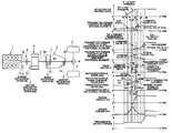
- FIG. 9 An example of the EV ⁇ HEV mode switching control according to the present invention is illustrated as shown in FIG. 9 .
- the EV ⁇ HEV mode switching is the switching from the electric running (EV) mode to drive driving wheels 2 by only power from motor-generator 5 by disengaging first clutch 6 , stopping engine 1 , and engaging second clutch 7 , to the hybrid running (HEV) mode and transmission 3 to a power transmitting permission state to drive driving wheels 2 by the power from engine 1 and motor-generator 5 by starting engine 1 by the power passing through the first clutch by engaging first clutch 6 .
- the EV ⁇ HEV mode switching is performed by engaging first clutch 6 , and by performing the driving force control of motor-generator 5 .
- the above-described downshift of automatic transmission 3 from the fifth speed to the fourth speed is attained by disengaging front brake Fr/B in the engagement state (referred to as disengagement side frictional element) and by engaging direct clutch D/C in the disengagement state (referred to as engagement side frictional element), as shown in arrows of the engagement logic diagram of FIG. 6 .
- High and low reverse clutch H&LR/C continuously keeps the engagement state during this shift as is clear from the engagement logic diagram of FIG. 6 , so that automatic transmission 3 is brought to the transmitting state at both the fifth speed and fourth speed before and after the shift.
- high and low reverse clutch H&LR/C is used as second clutch 7 of FIG. 3 .
- tTc 2 designates the command value of that transmitted torque capacity, and Tc 2 designates that actual value.
- tTc designates the command value relating to the transmitted torque capacity of direct clutch D/C (the engagement side frictional element), and Tc designates that actual value.
- tPc 1 designates the command pressure of first clutch 6
- Pc 1 designates that actual pressure
- Tc 1 designates the transmitted torque capacity.
- Transmitted torque capacity Tc 1 is decreased as actual pressure Pc 1 is increased to control to direct to that command pressure tPc 1 .
- rotational speed command value (motor rotational speed command value) tNm of motor-generator 5 actual rotational speed (motor rotational speed) Nm of motor-generator 5 , engine rotational speed Ne of engine 1 , transmission input rotational speed Ni of automatic transmission 3 , engine torque Te of engine 1 , motor torque Tm of motor-generator 5 , and the transmission output torque are indicated.
- motor torque Tm and motor rotational speed Nm of motor-generator 5 are increased with the increase of accelerator opening APO (request driving force) from instant t 1 . Accordingly, transmitted torque capacity Tc 2 of high and low reverse clutch H&LR/C of second clutch 7 is increased as shown in the diagram so as to transmit this motor torque Tm to driving wheels 2 .
- first clutch 6 is rapidly brought to an engagement initiation immediate preceding state, by actual pressure Pc 1 controlled to follow command pressure tPc 1 decreased as a broken line (by precharge control and a standby control), so as to remain the transmitted torque capacity to zero.
- rotational speed command value tNm of motor-generator 5 is increased to the target value for the engine starting, from instant t 3 at which set time TM 1 elapses from instant t 2 of the EV HEV mode switching, so that motor torque Tm is increased to follow motor rotational speed Nm accordingly.
- rotational speed tNm of motor-generator 5 is set to a sum of the target rotational speed for the engine starting and the difference between the driving and driven rotational speeds of second clutch 7 (high and low reverse clutch H&LR/C).
- Engine 1 initiates the starting by transmitted torque capacity Tc 1 by the start of engagement of first clutch 6 , as is clear from waveform of engine rotational speed Nm and engine torque Te.
- command pressure tPc 1 transmitted torque capacity Tc 1 immediate after instant t 4 is determined so that engine rotational speed Nm is increased to 1000 rpm by, for example, 0.3 sec.
- command pressure tPc 1 is set to zero.
- transmitted torque capacity Tc 1 is directed to the maximum value for completely engaging first clutch 6 by actual pressure Pc 1 controlled to decrease.
- transmitted torque capacity command value tTo of front brake Fr/B of the disengagement side frictional element is decreased to a value corresponding to the transmitted torque capacity of high and low reverse clutch H&LR/C of second clutch 7 , so that actual transmitted torque capacity To of front brake Fr/B of the disengagement side frictional element is decreased so as to follow transmitted torque capacity command value tTo.
- front brake Fr/B of the disengagement side frictional element can slip, instead of high and low reverse clutch H&LR/C of second clutch 7 .
- the start of the slip of front brake Fr/B is sensed, and transmitted torque capacity command value tTc 2 of high and low reverse clutch H&LR/C is increased to a value necessary for complete engagement, so that high and low reverse clutch H&LR/C is completely engaged by actual transmitted torque capacity Tc 2 controlled to follow this transmitted torque capacity command value tTc 2 . Accordingly, the replacement of the slip element from high and low reverse clutch H&LR/C to front brake Fr/B is performed.
- first clutch 6 On the above-described complete engagement judgment of first clutch 6 (shown as the complete engagement judgment in FIG. 9 ), it is possible to judge that first clutch 6 is completely engaged by either earlier one of a time when transmitted torque capacity Tc 1 capable of being supposed from the stroke quantity of first clutch 6 becomes a specified value, or a time when predetermined time period TM 2 elapses from instant t 6 .
- transmitted torque capacity command value tTo of front brake Fr/B of the disengagement side frictional element is directed to 0 by time variation gradient according to accelerator opening APO and vehicle speed VSP, and front brake Fr/B is completely disengaged from the slip state by actual transmitted torque capacity To controlled to follow accordingly.
- transmitted torque capacity command value tTc of direct clutch D/C of the engagement side frictional element is set to 0, direct clutch D/C is completely engaged by actual transmitted torque capacity Tc controlled to follow accordingly. Consequently, the 5 ⁇ 4 downshift is completed at instant t 9 .
- the timing of shifting from the completion of the EV ⁇ HEV mode switching control to the HEV mode control is a time that a predetermined margin time elapses from when the difference between driving and driven rotations of high and low reverse clutch H&LR/C of second clutch 7 becomes lower than a set value indicative of the completion of the engagement.
- transmitted torque capacity Tc 2 of second clutch 7 is set to the transmitted torque capacity according to the driving force request value by the driver, and subsequently the transmitted torque capacity of the disengagement side frictional element (front brake Fr/B) is a value corresponding to transmitted torque capacity Tc 2 of second clutch 7 , that is, the transmitted torque capacity according to the driver.
- the driving force to driving wheels is held to the driving force corresponding to the driving force request value by the driver, and the EV ⁇ HEV mode switching and the shift of automatic transmission 3 are performed. It is possible to solve the above-mentioned problem as to the escape feeling and to solve the above-described problem of the shock by absorbing the torque variation by the slip of second clutch 7 or the disengagement side frictional element (front brake Fr/B).
- the torque of motor-generator 5 is set to a large value which exceeds the driving force request value by the driver, and it is possible to perform the starting of engine 1 by the redundancy of the motor-generator torque while holding the driving force to driving wheels 2 , to the driving force according to the driving force request value by the driver. Moreover, it is possible to concurrently perform the shift during this engine starting by the disengagement of the disengagement side frictional element (front brake Fr/B) and the engagement of the engagement side frictional element (direct clutch D/C). Accordingly, it is possible to solve the other problem that the time period necessary for the engine starting and the shift is lengthened.
- second stage II sets transmitted torque capacity Tc 2 of second clutch 7 to transmitted torque capacity according to the driving force requirement value by the driver, and brings to the state in which the second clutch can slip in response to the torque which exceeds the driving force request value.
- next third stage III sets transmitted torque capacity To of the disengagement side frictional element (front brake Fr/B) to a value corresponding to transmitted torque capacity Tc 2 of second clutch 7 , that is, the transmitted torque capacity according to the driving force requirement value by the driver, and disengages second clutch 7 to perform the replacement of the slip element from second clutch 7 to the disengagement side frictional element (front brake Fr/B).
- a fourth stage IV starts the engagement of first clutch 6 , and starts the starting control of engine 1 by the same above-described control of motor-generator 5 .
- a fifth stage V continues the above-described transmitted torque capacity control of the disengagement side frictional element (front brake Fr/B), and brings to the state that the disengagement side frictional element (front brake Fr/B) can slip in response to the torque which exceeds the driving force request value by the driver.
- Next VI stage sets transmitted torque capacity Tc of direct clutch D/C of the engagement side frictional element, to a value corresponding to transmitted torque capacity To of the disengagement side frictional element (front brake Fr/B), that is, the transmitted torque capacity according to the transmitted torque capacity request value by the driver, and disengages the disengagement side frictional element (front brake Fr/B) to perform the shift by the replacement from the disengagement side frictional element (front brake Fr/B) to the engagement side frictional element (direct clutch D/C).
- the torque down for preventing the shift shock is performed by the torque control of engine 1 or motor-generator 5 .
- a seventh stage VII the shift is finished by the completion of the above-described engagement of the engagement side frictional element (direct clutch D/C), and it is possible to attain the HEV running mode at the fourth speed after the shift.
- Motor-generator 5 assists the response delay of the engine in this time to prevent the shock.
- This control corresponds to the control of FIG. 10 that third stage III is deleted.
- second stage II sets transmitted torque capacity To of the disengagement side frictional element to the transmitted torque capacity according to the driving force request value by the driver, and brings to the state that the disengagement side frictional element (front brake Fr/B) can slip in response to the torque which exceeds the driving force request value.
- next fourth stage IV starts the engagement of first clutch 6 , and starts the starting control of engine 1 by the same above-described control of motor-generator 5 .
- fifth stage V continues the above-described transmitted torque capacity control of the disengagement side frictional element (front brake Fr/B), and brings to the state that the disengagement side frictional element (front brake Fr/B) can slip in response to the torque which exceeds the driving force request value by the driver.
- Next sixth stage VI sets transmitted torque capacity Tc of direct clutch D/C of the engagement side frictional element, to a value corresponding to transmitted torque capacity To of the disengagement side frictional element (front brake Fr/B), that is, the transmitted torque capacity according to the driving force request value by the driver, and disengages the disengagement side frictional element (front brake Fr/B) to perform the shift by the replacement from the disengagement side frictional element (front brake Fr/B) to the engagement side frictional element (direct clutch D/C).
- the torque down for preventing the shift shock is performed by the torque control of engine 1 or motor-generator 5 .
- FIG. 12 shows a control in a case in which the disengagement side frictional element (front brake Fr/B) is commonly used as second clutch 7 and there is a shift request after the EV ⁇ HEV mode switching request (the engine starting request).
- front brake Fr/B front brake Fr/B
- This control corresponds to the control that is described above with reference to FIG. 9 , except that the replacement stage from second clutch 7 to front brake Fr/B of the disengagement side frictional element is deleted.
- second stage II sets transmitted torque capacity To of the disengagement side frictional element (front brake Fr/B) in the engagement state, to the transmitted torque capacity according to the driving force request value by the driver, and brings to the state in which the disengagement side frictional element (front brake Fr/B) can slip in response to the torque which exceeds the driving force request value.
- next third stage III engages first clutch 6 in response to the engine starting request, and starts the starting control of engine 1 by the same above-described control of motor-generator 5 .
- fourth stage IV continues the above-described transmitted torque capacity control of the disengagement side frictional element (front brake Fr/B), and brings to the state that the disengagement side frictional element (front brake Fr/B) can slip in response to the torque which exceeds the driving force request value by the driver.
- next fifth stage V sets transmitted torque capacity Tc of direct clutch D/C of the engagement side frictional element to the value corresponding to transmitted torque capacity To of the disengagement side frictional element (front brake Fr/B), that is, the transmitted torque capacity according to the driving force request value by the driver, and disengages the disengagement side frictional element (front brake Fr/B) to perform the shift by the replacement from the disengagement side frictional element (front brake Fr/B) to the engagement side frictional element (direct clutch D/C).
- the torque down for preventing the shift shock is performed by the torque control of engine 1 or motor-generator 5 .
- FIG. 13 shows a control in a case in which the engagement side frictional element (direct clutch D/C) is commonly used as second clutch 7 and there is the shift request before the EV ⁇ HEV mode switching request (the engine starting request).
- direct clutch D/C direct clutch D/C
- second stage II sets transmitted torque capacity Tc of the engagement side frictional element (direct clutch D/C) in the disengagement state to the transmitted torque capacity according to the driving force request value by the driver, permits the engagement side frictional element (direct clutch D/C) to slip in response to the torque which exceeds the driving force request value, and starts the disengagement of front brake Fr/B of the disengagement side frictional element.
- next third stage III starts the engagement of first clutch 6 in response to the engine starting request, and starts the starting control of engine 1 by the same above-described control of motor-generator 5 .
- fourth stage IV continues the above-described transmitted torque capacity control of the engagement side frictional element (direct clutch D/C), and permits the engagement side frictional element (direct clutch D/C) to slip in response to the torque which exceeds the driving force request value by the driver.
- the direct clutch D/C of the engagement side frictional element is engaged in response to the shift request, and the shift is performed by the replacement from the disengagement side frictional element (front brake Fr/B) to the engagement side frictional element (direct clutch D/C).
- the torque down for preventing the shift shock is performed by the torque control of engine 1 or motor-generator 5 .
- the shift is finished by the completion of the engagement of the engagement side frictional element (direct clutch D/C), and it is possible to attain the HEV running mode at the fourth speed after the shift.
- the shock is prevented by assisting the response delay at this time by motor-generator 5 .
- FIG. 14 shows a control in a case in which the engagement side frictional element (direct clutch D/C) is commonly used as second clutch 7 and there is the shift request after the EV HEV mode switching request (the engine starting request).
- direct clutch D/C direct clutch D/C
- second stage II sets transmitted torque capacity Tc of the engagement side frictional element (direct clutch D/C) in the disengagement state to the transmitted torque capacity according to the driving force request value by the driver, permits the engagement side frictional element (direct clutch D/C) to slip in response to the torque which exceeds the driving force request value, and starts the disengagement of front brake Fr/B of the disengagement side frictional element.
- the next third stage III starts the engagement of first clutch 6 in response to the engine starting request, and starts the starting control of engine 1 by the same above-described control of motor-generator 5 .
- fourth stage IV continues the above-described transmitted torque capacity control of the engagement side frictional element (direct clutch D/C), permits the engagement side frictional element (direct clutch D/C) to slip in response to the torque which exceeds the driving force request value by the driver, and finishes the disengagement of front brake Fr/B of the disengagement side frictional element during this time period.
- the shift is finished by the completion of the above-described engagement of the engagement side frictional element (direct clutch D/C), and it is possible to attain the HEV running mode at the fourth speed after the shift.
- the shock is prevented by assisting the response delay of the engine at this time by motor-generator 5 .
- FIG. 15 shows a control at the shift in the HEV mode in a case in which the disengagement side frictional element (front brake Fr/B) and the engagement side frictional element (direct clutch D/C) are different from each other.
- first stage I sets transmitted torque capacity Tc 2 of second clutch 7 in the engagement state, to the transmitted torque capacity according to the driving force request value by the driver, and brings to the state that second clutch 7 can slip in response to the torque which exceeds the driving force request value.
- the next stage II sets transmitted torque capacity To of front brake Fr/B of the disengagement side frictional element to the value corresponding to transmitted torque capacity Tc 2 of second clutch 7 , that is, the transmitted torque capacity according to the driving force request value by the driver, and performs the replacement of the slip clutch from second clutch 7 to the disengagement side frictional element (front brake Fr/B) by the engagement of second clutch 7 . Consequently, it is possible to slip the disengagement side frictional element (front brake Fr/B) in response to the torque which exceeds the driving force request value, instead of second clutch 7 .
- the next third stage III sets transmitted torque capacity Tc of the engagement side frictional element (direct clutch D/C) to the value corresponding to transmitted torque capacity To of the disengagement side frictional element (front brake Fr/B), that is, the transmitted torque capacity according to the driving force request value by the driver, and permits the engagement side frictional element (direct clutch D/C) to slip in response to the torque that exceeds the driving force request value, instead of the disengagement side frictional element (front brake Fr/B).
- the third stage III disengages the disengagement side frictional element (front brake Fr/B) by disappearance of transmitted torque capacity To.
- FIG. 16 shows a control at a shift in the HEV mode in a case in which the disengagement side frictional element (front brake Fr/B) is commonly used as second clutch 7 .
- This control corresponds to a control which the second stage II is deleted from FIG. 15 , and which second clutch 7 of the first stage I is displaced by the disengagement side frictional element (front brake Fr/B).
- the first stage I sets transmitted torque capacity To of the disengagement side frictional element (front brake Fr/B) in the engagement state to the transmitted torque capacity according to the driving force request value by the driver, and permits the disengagement side frictional element (front brake Fr/B) to slip in response to the torque which exceeds the driving force request value.
- the next third stage III sets transmitted torque capacity Tc of the engagement side frictional element (direct clutch D/C) to the value corresponding to transmitted torque capacity To of the disengagement side frictional element (front brake Fr/B), that is, the transmitted torque capacity according to the driving force request value by the driver, and permits the engagement side frictional element (direct clutch D/C) to slip in response to the torque which exceeds the driving force request value, instead of the disengagement side frictional element (front brake Fr/B). Moreover, the third stage III disengages the disengagement side frictional element (front brake Fr/B) by the disappearance of transmitted torque capacity To.
- FIG. 17 shows a control at a shift in the HEV mode that the engagement side frictional element (direct clutch D/C) is commonly used as second clutch 7 .
- the first stage I sets transmitted torque capacity Tc of the engagement side frictional element (direct clutch D/C) in the disengagement state to the transmitted torque capacity according to the driving force request value by the driver, and permits the engagement side frictional element (direct clutch D/C) to slip in response to the torque which exceeds the driving force request value.
- the second stage II keeps the engagement side frictional element (direct clutch D/C) to the above-described transmitted torque capacity control state.
- the shift is performed by the replacement from the engagement side frictional element (direct clutch D/C) to the disengagement side frictional element (front brake Fr/B), by the disengagement of the engagement side frictional element (direct clutch D/C) and the engagement of the engagement side frictional element (direct clutch D/C) in the fourth stage IV.
- the engagement side frictional element (direct clutch D/C) is rapidly brought to the engagement immediately preceding state by the precharge and standby control.
- the 5 ⁇ 4 downshift of automatic transmission holds the engagement state of high and low reverse clutch H&LR/C during this shift, and high and low reverse clutch H&LR/C is used as second clutch 7 (see FIG. 3 ). Accordingly, there is no need for providing a new second clutch 7 as shown in FIGS. 1 and 2 , and it is advantageous in the cost and the space.
- the transmitted torque capacity of the disengagement side frictional element (front brake Fr/B) or the engagement side frictional element (direct clutch D/C) serving as second clutch 7 is continuously held to the transmitted torque capacity according to the driving force request value by the driver, and accordingly it is possible to attain the same effect and the operation as described with reference to FIG. 9 .
- first clutch 6 when the vehicle is in the electric mode, first clutch 6 is disengaged and transmission 3 is brought to a power transmitting permission state.
- first clutch 6 When the vehicle is in hybrid running mode, first clutch 6 is engaged and transmission 3 is adapted to the power transmitting state in response to a requested vehicle driving force.
- the termination judgment of the replacement between the transmitted torque capacity control of the second clutch and the transmitted torque capacity control of the disengagement side frictional elements is performed by the transmitted torque capacity of the disengagement side frictional element, the difference of the driving and driven rotations of the clutch, and the elapse of the setting time period, and that the second clutch is engaged at the replacement termination judgment.
- the initiation of the disengagement of the disengagement side frictional element and the initiation of the engagement of the engagement side frictional element can be set to a time that the effective gear ratio between the motor-generator and the engine becomes the setting gear ratio, or the time that the setting time elapses from the request of the shift.
Landscapes
- Engineering & Computer Science (AREA)
- Transportation (AREA)
- Mechanical Engineering (AREA)
- Chemical & Material Sciences (AREA)
- Combustion & Propulsion (AREA)
- Power Engineering (AREA)
- Automation & Control Theory (AREA)
- Hybrid Electric Vehicles (AREA)
- Electric Propulsion And Braking For Vehicles (AREA)
- Control Of Vehicle Engines Or Engines For Specific Uses (AREA)
- Control Of Transmission Device (AREA)
- Hydraulic Clutches, Magnetic Clutches, Fluid Clutches, And Fluid Joints (AREA)
Applications Claiming Priority (2)
| Application Number | Priority Date | Filing Date | Title |
|---|---|---|---|
| JP2006-091547 | 2006-03-29 | ||
| JP2006091547A JP2007261498A (ja) | 2006-03-29 | 2006-03-29 | ハイブリッド車両の伝動状態切り替え制御装置 |
Publications (2)
| Publication Number | Publication Date |
|---|---|
| US20070227790A1 US20070227790A1 (en) | 2007-10-04 |
| US7878281B2 true US7878281B2 (en) | 2011-02-01 |
Family
ID=38197824
Family Applications (1)
| Application Number | Title | Priority Date | Filing Date |
|---|---|---|---|
| US11/728,732 Active 2029-09-26 US7878281B2 (en) | 2006-03-29 | 2007-03-27 | Transmitting state switching control apparatus for hybrid vehicle |
Country Status (4)
| Country | Link |
|---|---|
| US (1) | US7878281B2 (de) |
| EP (1) | EP1839987B1 (de) |
| JP (1) | JP2007261498A (de) |
| CN (1) | CN101045451B (de) |
Cited By (29)
| Publication number | Priority date | Publication date | Assignee | Title |
|---|---|---|---|---|
| US20080264051A1 (en) * | 2005-10-14 | 2008-10-30 | Volvo Construction Equipment Ab | Working Machine and a Method for Operating a Working Machine |
| US20080293538A1 (en) * | 2007-05-02 | 2008-11-27 | Nissan Motor Co., Ltd. | Hybrid vehicle drive control apparatus and method |
| US20090017988A1 (en) * | 2007-07-05 | 2009-01-15 | Luk Lamellen Und Kupplungsbau Beteiligungs Kg | Method for controlling a starting clutch |
| US20100156210A1 (en) * | 2008-12-19 | 2010-06-24 | Tai-Her Yang | Bidirectional unequal speed electric motor driven constant directional output system |
| US20100304925A1 (en) * | 2007-10-24 | 2010-12-02 | Zf Friedrichshafen Ag | Motor vehicle control system |
| US20100304923A1 (en) * | 2006-10-23 | 2010-12-02 | Robert Bosch Gmbh | Method For Controlling A Hybrid Drive |
| US20100318251A1 (en) * | 2007-10-24 | 2010-12-16 | Zf Friedrichshafen Ag | Motor vehicle control system |
| US20110039655A1 (en) * | 2007-12-13 | 2011-02-17 | Johannes Kaltenbach | Method and device for controlling a creep mode of a vehicle having a hybrid drive system |
| US20110048822A1 (en) * | 2007-12-17 | 2011-03-03 | Johannes Kaltenbach | Method and device for controlling a creep operation of a vehicle with a hybrid drive |
| US20110093147A1 (en) * | 2007-12-17 | 2011-04-21 | Johannes Kaltenbach | Method and device for operating a hybrid drive of a vehicle |
| US20110166726A1 (en) * | 2007-10-24 | 2011-07-07 | Zf Friedrichshafen Ag | Motor vehicle control system |
| US20120065023A1 (en) * | 2010-09-14 | 2012-03-15 | Gm Global Technology Operations, Inc. | System and method for controlling amount of time needed to commence transmitting engine torque in a vehicle |
| US8143822B2 (en) * | 2008-12-19 | 2012-03-27 | Tai-Her Yang | Bidirectional unequal speed electric motor driven bidirectional output system |
| US8143823B2 (en) * | 2008-12-19 | 2012-03-27 | Tai-Her Yang | Bidirectional different speed ratio electric motor driving device with bidirectional input |
| US8143821B2 (en) * | 2008-12-19 | 2012-03-27 | Tai-Her Yang | Bidirectional unequal speed electric motor driven constant directional output system |
| US20120088621A1 (en) * | 2010-09-28 | 2012-04-12 | Aisin Aw Co., Ltd. | Transmission apparatus and shift control apparatus |
| US20120202646A1 (en) * | 2011-02-03 | 2012-08-09 | Jatco Ltd | Control apparatus for hybrid vehicle |
| US20130012353A1 (en) * | 2011-07-06 | 2013-01-10 | Aisin Aw Co., Ltd. | Control device |
| US20130178330A1 (en) * | 2012-01-11 | 2013-07-11 | Ford Global Technologies, Llc | Hybrid vehicle and control for a clutch engaging event |
| US20130211654A1 (en) * | 2010-10-26 | 2013-08-15 | Kaori Tanisshima | Engine start control device for hybrid electric vehicle |
| US8517892B2 (en) * | 2011-08-08 | 2013-08-27 | Bae Systems Controls Inc. | Method and apparatus for controlling hybrid electric vehicles |
| US8663062B2 (en) | 2011-08-30 | 2014-03-04 | Aisin Aw Co., Ltd. | Control device |
| US20140081500A1 (en) * | 2011-02-21 | 2014-03-20 | Yoshiki Ito | Drive control device of hybrid vehicle |
| US20140114518A1 (en) * | 2011-02-01 | 2014-04-24 | Jaguar Land Rover Limited | Hybrid electric vehicle controller and method of controlling a hybrid electric vehicle |
| US20150080174A1 (en) * | 2013-09-19 | 2015-03-19 | Borgwarner, Inc. | Multimode Clutch for a Parallel Hybrid Vehicle |
| US9061681B2 (en) | 2011-07-06 | 2015-06-23 | Aisin Aw Co., Ltd. | Control device |
| US20150210152A1 (en) * | 2014-01-30 | 2015-07-30 | Amp Electric Vehicles Inc. | Onboard generator drive system for electric vehicles |
| US10293692B2 (en) | 2016-10-17 | 2019-05-21 | Toyota Motor Engineering & Manufacturing North America, Inc. | Motor generated assist torque control for hybrid vehicles |
| US20220097679A1 (en) * | 2020-09-30 | 2022-03-31 | Toyota Jidosha Kabushiki Kaisha | Control device for vehicle |
Families Citing this family (71)
| Publication number | Priority date | Publication date | Assignee | Title |
|---|---|---|---|---|
| JP2007112258A (ja) * | 2005-10-19 | 2007-05-10 | Nissan Motor Co Ltd | ハイブリッド駆動装置のエンジン始動制御装置 |
| JP2008201229A (ja) * | 2007-02-19 | 2008-09-04 | Toyota Motor Corp | 車両用駆動装置の制御装置 |
| JP4561760B2 (ja) * | 2007-03-05 | 2010-10-13 | トヨタ自動車株式会社 | 車両用駆動装置の制御装置 |
| US8688299B2 (en) * | 2007-05-02 | 2014-04-01 | Nissan Motor Co., Ltd. | Mode change control system for hybrid vehicle |
| US7846051B2 (en) * | 2007-05-11 | 2010-12-07 | Gm Global Technology Operations, Inc. | Hybrid powertrain with an engine input clutch and method of control |
| DE102007038771B4 (de) * | 2007-08-16 | 2025-03-20 | Zf Friedrichshafen Ag | Verfahren zum Starten des Verbrennungsmotors während einer Lastschaltung bei parallelen Hybridfahrzeugen |
| DE102007045367A1 (de) * | 2007-09-22 | 2009-04-02 | Zf Friedrichshafen Ag | Verfahren zum Betreiben eines Antriebsstrangs |
| US8489293B2 (en) * | 2007-10-29 | 2013-07-16 | GM Global Technology Operations LLC | Method and apparatus to control input speed profile during inertia speed phase for a hybrid powertrain system |
| US8170764B2 (en) * | 2007-11-02 | 2012-05-01 | GM Global Technology Operations LLC | Method and apparatus to reprofile input speed during speed during speed phase during constrained conditions for a hybrid powertrain system |
| DE102007047818A1 (de) * | 2007-11-20 | 2009-05-28 | Zf Friedrichshafen Ag | Verfahren zur Bestimmung des Istzustandes eines Hybridantriebsstrangs |
| JP5167786B2 (ja) * | 2007-11-29 | 2013-03-21 | 日産自動車株式会社 | ハイブリッド車両の制御装置 |
| DE102008000045A1 (de) * | 2008-01-14 | 2009-07-16 | Zf Friedrichshafen Ag | Verfahren zum Betreiben eines Antriebsstrangs |
| JP5104406B2 (ja) * | 2008-03-03 | 2012-12-19 | 日産自動車株式会社 | ハイブリッド車両のエンジン始動制御装置 |
| JP5262197B2 (ja) * | 2008-03-10 | 2013-08-14 | 日産自動車株式会社 | ハイブリッド車両の制御装置 |
| JP5228677B2 (ja) * | 2008-07-30 | 2013-07-03 | 日産自動車株式会社 | ハイブリッド車両の制御装置 |
| JP5024274B2 (ja) * | 2008-12-19 | 2012-09-12 | 日産自動車株式会社 | ハイブリッド車両のエンジン始動制御装置 |
| JP5233658B2 (ja) * | 2008-12-24 | 2013-07-10 | 日産自動車株式会社 | ハイブリッド車両のエンジン始動制御装置 |
| JP5233659B2 (ja) * | 2008-12-24 | 2013-07-10 | 日産自動車株式会社 | ハイブリッド車両のエンジン始動制御装置 |
| JP5338332B2 (ja) * | 2009-01-20 | 2013-11-13 | 日産自動車株式会社 | ハイブリッド車両の制御装置 |
| JP5218152B2 (ja) * | 2009-02-26 | 2013-06-26 | 日産自動車株式会社 | 電動車両の制御装置 |
| JP5359387B2 (ja) * | 2009-03-06 | 2013-12-04 | 日産自動車株式会社 | ハイブリッド車両のエンジン始動制御装置 |
| US9168825B2 (en) | 2009-05-15 | 2015-10-27 | Ford Global Technologies, Llc | Hybrid electric vehicle and method for controlling a powertrain therein |
| JP5593644B2 (ja) * | 2009-07-15 | 2014-09-24 | 日産自動車株式会社 | ハイブリッド車両の制御装置 |
| KR20120021093A (ko) * | 2010-08-31 | 2012-03-08 | 현대자동차주식회사 | 하이브리드 차량의 변속 제어장치 및 방법 |
| JP5614228B2 (ja) * | 2010-10-19 | 2014-10-29 | 日産自動車株式会社 | ハイブリッド車両の制御装置 |
| US8989936B2 (en) * | 2010-10-19 | 2015-03-24 | Nissan Motor Co., Ltd. | Hybrid vehicle control system |
| JP5373201B2 (ja) * | 2010-10-21 | 2013-12-18 | 日野自動車株式会社 | 走行モード切替制御装置、ハイブリッド自動車および走行モード切替制御方法、並びにプログラム |
| JP2012086738A (ja) * | 2010-10-21 | 2012-05-10 | Nissan Motor Co Ltd | ハイブリッド車両のモード切り替え制御装置 |
| US8731761B2 (en) * | 2010-10-22 | 2014-05-20 | Hino Motors, Ltd. | Vehicle, control method, and computer program |
| US8798836B2 (en) | 2010-10-25 | 2014-08-05 | Nissan Motor Co., Ltd. | Control device for hybrid vehicle |
| CN103249625B (zh) * | 2010-10-26 | 2015-10-21 | 日产自动车株式会社 | 混合动力车辆的控制装置 |
| JP2012091620A (ja) * | 2010-10-26 | 2012-05-17 | Nissan Motor Co Ltd | ハイブリッド車両のエンジン始動制御装置 |
| US8996265B2 (en) * | 2011-01-12 | 2015-03-31 | Toyota Jidosha Kabushiki Kaisha | Control device of hybrid vehicle |
| JP5730912B2 (ja) | 2011-01-28 | 2015-06-10 | 日産自動車株式会社 | ハイブリッド車両の制御装置 |
| US8798838B2 (en) | 2011-01-28 | 2014-08-05 | Nissan Motor Co., Ltd. | Hybrid vehicle control device |
| US8771136B2 (en) * | 2011-06-10 | 2014-07-08 | GM Global Technology Operations LLC | Hybrid powertrain with operator selectable electric propulsion mode |
| US9216731B2 (en) * | 2011-06-30 | 2015-12-22 | Nissan Motor Co., Ltd. | Control device for hybrid vehicle |
| US8849489B2 (en) * | 2011-07-29 | 2014-09-30 | Chrysler Group Llc | Shift execution control system for an electrically variable transmission |
| JP5505734B2 (ja) | 2011-08-08 | 2014-05-28 | アイシン・エィ・ダブリュ株式会社 | 制御装置 |
| JP5472227B2 (ja) * | 2011-08-08 | 2014-04-16 | アイシン・エィ・ダブリュ株式会社 | 制御装置 |
| JP5565637B2 (ja) * | 2011-08-24 | 2014-08-06 | アイシン・エィ・ダブリュ株式会社 | 制御装置 |
| CN102991495B (zh) * | 2011-09-14 | 2015-05-20 | 北汽福田汽车股份有限公司 | 混合动力汽车及用于其的离合器的接合控制方法和装置 |
| CN103842225B (zh) * | 2011-11-25 | 2016-06-22 | 日产自动车株式会社 | 混合动力车辆的控制装置 |
| US9487205B2 (en) * | 2011-11-29 | 2016-11-08 | Toyota Jidosha Kabushiki Kaisha | Controller of hybrid system |
| JP5915245B2 (ja) * | 2012-02-22 | 2016-05-11 | 日産自動車株式会社 | ハイブリッド車両の制御装置 |
| US8538643B1 (en) * | 2012-04-13 | 2013-09-17 | Ford Global Technologies, Llc | Active damping during clutch engagement for engine start |
| DE102013208033A1 (de) * | 2012-05-04 | 2013-11-07 | Ford Global Technologies, Llc | Verfahren und Systeme für ein Hybridfahrzeug |
| CN104837699B (zh) * | 2012-12-07 | 2018-05-01 | 日产自动车株式会社 | 混合动力车辆的模式切换控制装置 |
| JP6064611B2 (ja) * | 2013-01-17 | 2017-01-25 | アイシン・エィ・ダブリュ株式会社 | 車両用駆動装置の制御装置 |
| US9028365B2 (en) * | 2013-03-13 | 2015-05-12 | Ford Global Technologies, Llc | Method of shifting a transmission |
| JP6217125B2 (ja) * | 2013-05-08 | 2017-10-25 | 日産自動車株式会社 | ハイブリッド車両の制御装置 |
| JP6187059B2 (ja) * | 2013-09-09 | 2017-08-30 | 日産自動車株式会社 | ハイブリッド車両の制御装置 |
| DE102014200253B4 (de) * | 2013-10-02 | 2015-12-17 | Volkswagen Aktiengesellschaft | Verfahren zum Starten einer Verbrennungskraftmaschine eines Hybridfahrzeuges und Hybridfahrzeug |
| CN104565128B (zh) * | 2013-10-23 | 2017-10-13 | 大陆汽车投资(上海)有限公司 | 混合动力机动车的离合器控制方法、装置及系统 |
| KR101510343B1 (ko) * | 2013-10-31 | 2015-04-07 | 현대자동차 주식회사 | 플러그인 하이브리드 자동차의 방전지향모드 제어장치 및 방법 |
| KR101481335B1 (ko) * | 2013-11-20 | 2015-01-09 | 현대자동차주식회사 | 하이브리드 차량의 변속제어방법 |
| WO2015130614A1 (en) * | 2014-02-25 | 2015-09-03 | Cummins, Inc. | Power regeneration optimization in a hybrid vehicle |
| US9688268B2 (en) * | 2014-06-12 | 2017-06-27 | Ford Global Technologies, Llc | Method for controlling an electric machine in a vehicle with an engine disconnect clutch |
| JP6512760B2 (ja) * | 2014-06-26 | 2019-05-15 | 日産自動車株式会社 | ハイブリッド車両の制御装置 |
| US9238460B1 (en) * | 2014-07-23 | 2016-01-19 | Toyota Motor Corporation | Systems for managing downshifts in hybrid-electric vehicles |
| CN104670218A (zh) * | 2014-12-14 | 2015-06-03 | 励春亚 | 混联式混合动力系统分层结构多能源综合控制方法 |
| JP6260564B2 (ja) * | 2015-03-25 | 2018-01-17 | トヨタ自動車株式会社 | ハイブリッド車両の駆動装置 |
| US10300908B2 (en) * | 2015-03-31 | 2019-05-28 | Aisin Aw Co., Ltd. | Control device for starting an internal combustion engine during a shifting operation |
| DE112016003361T5 (de) * | 2015-09-30 | 2018-04-05 | Aisin Aw Co., Ltd. | Steuerungsvorrichtung |
| JP6958455B2 (ja) * | 2018-03-28 | 2021-11-02 | トヨタ自動車株式会社 | 車両の制御装置 |
| CN108528426A (zh) * | 2018-05-15 | 2018-09-14 | 舍弗勒技术股份两合公司 | 混合动力汽车的控制方法及控制装置 |
| CN110194144B (zh) * | 2019-05-05 | 2020-10-23 | 中国第一汽车股份有限公司 | 混合动力汽车起动发动机的电机扭矩控制方法及装置 |
| US11413960B2 (en) * | 2019-07-12 | 2022-08-16 | Deere & Company | Power shift transmission with electric power assist |
| CN113104020A (zh) * | 2019-12-24 | 2021-07-13 | 北京宝沃汽车股份有限公司 | 混合动力汽车及其动力控制模式的决策方法、装置 |
| JP2021138309A (ja) * | 2020-03-06 | 2021-09-16 | 本田技研工業株式会社 | 車両 |
| CN115605382B (zh) * | 2020-07-24 | 2025-07-25 | 舍弗勒技术股份两合公司 | 发动机启动方法 |
Citations (35)
| Publication number | Priority date | Publication date | Assignee | Title |
|---|---|---|---|---|
| US5400678A (en) * | 1992-10-30 | 1995-03-28 | Ford Motor Company | Line pressure optimization in an automatic transmission |
| JPH102241A (ja) | 1996-04-19 | 1998-01-06 | Toyota Motor Corp | ハイブリッド車両の制御装置 |
| US5720690A (en) * | 1995-06-16 | 1998-02-24 | Aisin Aw Co., Ltd. | Shift control system for controlling a transmission of a vehicle having an engine and a motor generator drive source |
| JPH1182260A (ja) | 1997-08-29 | 1999-03-26 | Aisin Aw Co Ltd | 車両用ハイブリッド駆動装置 |
| US5947863A (en) * | 1996-12-20 | 1999-09-07 | Robert Bosch Gmbh | Method and arrangement for controlling the input torque of a transmission |
| US6018198A (en) * | 1997-08-29 | 2000-01-25 | Aisin Aw Co., Ltd. | Hybrid drive apparatus for vehicle |
| US6083138A (en) * | 1998-03-20 | 2000-07-04 | Nissan Motor Co., Ltd. | Hybrid drive control system for vehicle |
| JP2000224714A (ja) | 1999-02-03 | 2000-08-11 | Mitsubishi Motors Corp | 電動機付車両 |
| US6176807B1 (en) * | 1998-01-16 | 2001-01-23 | Toyota Jidosha Kabushiki Kaisha | Drive control system for hybrid vehicles |
| US6338391B1 (en) * | 1999-03-01 | 2002-01-15 | Paice Corporation | Hybrid vehicles incorporating turbochargers |
| US6364807B1 (en) * | 2000-06-30 | 2002-04-02 | Ford Global Technologies, Inc. | Control strategy for a hybrid powertrain for an automotive vehicle |
| US6368249B1 (en) * | 2000-05-19 | 2002-04-09 | General Motors Corporation | Driver responsive power-on downshift control |
| US6524219B2 (en) * | 2000-08-02 | 2003-02-25 | C.R.F. Societa Consortile Per Azioni | Method and a system for controlling the propulsion of a motor vehicle |
| US6581705B2 (en) * | 2001-06-29 | 2003-06-24 | Ford Global Technologies, Llc | Method for starting an engine in a parallel hybrid electric vehicle |
| US20030153429A1 (en) * | 2001-11-29 | 2003-08-14 | Daimlerchrysler Ag | Motor vehicle drive |
| US6692406B2 (en) * | 2001-08-29 | 2004-02-17 | Eaton Corporation | Shift control strategy for use with an automated manual transmission coupled to a turbocharged internal combustion engine |
| US20040152558A1 (en) * | 2002-12-27 | 2004-08-05 | Aisin Aw Co., Ltd. | Control device for a hybrid vehicle |
| US6847880B2 (en) * | 2000-05-16 | 2005-01-25 | Nissan Motor Co., Ltd. | Gear shifting on target speed reduction in vehicle speed control system |
| US6852062B1 (en) * | 1999-07-27 | 2005-02-08 | Robert Bosch Gmbh | Drive system for motor vehicles |
| US20050054480A1 (en) * | 2003-09-10 | 2005-03-10 | Ford Global Technologies, Llc | Hybrid vehicle powertrain with a multiple-ratio power transmission mechanism |
| US20050090370A1 (en) * | 2002-04-10 | 2005-04-28 | Luk Lamellen Und Kupplungsbau Beteiligungs Kg | Method, device and use thereof for operating a motor vehicle |
| US20050155803A1 (en) * | 2004-01-15 | 2005-07-21 | Peter Schiele | Method for controlling and regulating a powertrain of a hybrid vehicle and powertrain of a hybrid vehicle |
| US20050197233A1 (en) * | 2002-02-04 | 2005-09-08 | Toyota Jidosha Kabushiki Kaisha | Control apparatus for power train including continuously variable transmission |
| US6997275B2 (en) * | 2000-02-04 | 2006-02-14 | C.R.F. Societa Consortile Per Azioni | Method and a system for controlling the propulsion of a hybrid motor vehicle |
| US7062986B2 (en) * | 2002-10-09 | 2006-06-20 | Luk Lamellen Und Kupplungsbau Beteiligungs Kg | Methods and apparatus for operating a motor vehicle |
| US7131933B2 (en) * | 2001-12-07 | 2006-11-07 | Toyota Jidosha Kabushiki Kaisha | Vehicle control apparatus having means for changing inertia torque of engine during shifting action or during switching of operating state of lock-up clutch |
| US20070056783A1 (en) * | 2005-09-08 | 2007-03-15 | Nissan Motor Co., Ltd. | Engine starting control device for a hybrid vehicle |
| US20070102208A1 (en) * | 2005-11-07 | 2007-05-10 | Nissan Motor Co., Ltd. | Hybrid vehicle control system |
| US20070102205A1 (en) * | 2005-11-07 | 2007-05-10 | Nissan Motor Co., Ltd. | Hybrid vehicle control system |
| US20070102207A1 (en) * | 2005-11-07 | 2007-05-10 | Nissan Motor Co., Ltd. | Hybrid vehicle drive control system |
| US20070275823A1 (en) * | 2006-05-26 | 2007-11-29 | Nissan Motor Co., Ltd. | Clutch engagement control apparatus for hybrid vehicle |
| US20070276557A1 (en) * | 2006-05-26 | 2007-11-29 | Nissan Motor Co., Ltd. | Clutch engagement control apparatus and method for hybrid vehicle |
| US20080006457A1 (en) * | 2006-07-05 | 2008-01-10 | Nissan Motor Co., Ltd. | Motor lock prevention control for hybrid vehicle |
| US20080071437A1 (en) * | 2005-12-12 | 2008-03-20 | Takeshi Hirata | Control Unit For Controlling An Engine Stop Of A Hybrid Vehicle |
| US7347803B2 (en) * | 2004-10-27 | 2008-03-25 | Aisin Aw Co., Ltd. | Drive apparatus for hybrid vehicle and control method and control device thereof |
Family Cites Families (5)
| Publication number | Priority date | Publication date | Assignee | Title |
|---|---|---|---|---|
| EP1038346A2 (de) * | 1997-10-21 | 2000-09-27 | Stridsberg Innovation Ab | Hybridantrieb |
| US5943911A (en) * | 1998-05-11 | 1999-08-31 | Borg-Warner Automotive, Inc. | Electromechanical friction clutch control for a manual transmission |
| US6823954B2 (en) * | 2001-05-18 | 2004-11-30 | Honda Giken Kogyo Kabushiki Kaisha | Control system for hybrid vehicle |
| JP3922549B2 (ja) * | 2002-07-10 | 2007-05-30 | スズキ株式会社 | 車両の制御装置 |
| FR2882697B1 (fr) * | 2005-03-01 | 2008-10-31 | Peugeot Citroen Automobiles Sa | Procede de changement de rapport de vitesse |
-
2006
- 2006-03-29 JP JP2006091547A patent/JP2007261498A/ja active Pending
-
2007
- 2007-03-27 CN CN2007100895238A patent/CN101045451B/zh active Active
- 2007-03-27 US US11/728,732 patent/US7878281B2/en active Active
- 2007-03-27 EP EP07104967A patent/EP1839987B1/de not_active Ceased
Patent Citations (40)
| Publication number | Priority date | Publication date | Assignee | Title |
|---|---|---|---|---|
| US5400678A (en) * | 1992-10-30 | 1995-03-28 | Ford Motor Company | Line pressure optimization in an automatic transmission |
| US5720690A (en) * | 1995-06-16 | 1998-02-24 | Aisin Aw Co., Ltd. | Shift control system for controlling a transmission of a vehicle having an engine and a motor generator drive source |
| JPH102241A (ja) | 1996-04-19 | 1998-01-06 | Toyota Motor Corp | ハイブリッド車両の制御装置 |
| US5947863A (en) * | 1996-12-20 | 1999-09-07 | Robert Bosch Gmbh | Method and arrangement for controlling the input torque of a transmission |
| JPH1182260A (ja) | 1997-08-29 | 1999-03-26 | Aisin Aw Co Ltd | 車両用ハイブリッド駆動装置 |
| US6018198A (en) * | 1997-08-29 | 2000-01-25 | Aisin Aw Co., Ltd. | Hybrid drive apparatus for vehicle |
| US6176807B1 (en) * | 1998-01-16 | 2001-01-23 | Toyota Jidosha Kabushiki Kaisha | Drive control system for hybrid vehicles |
| US6083138A (en) * | 1998-03-20 | 2000-07-04 | Nissan Motor Co., Ltd. | Hybrid drive control system for vehicle |
| JP2000224714A (ja) | 1999-02-03 | 2000-08-11 | Mitsubishi Motors Corp | 電動機付車両 |
| US6244368B1 (en) * | 1999-02-03 | 2001-06-12 | Mitsubishi Jidosha Kogyo Kabushiki Kaisha | Hybrid powered vehicle |
| US6338391B1 (en) * | 1999-03-01 | 2002-01-15 | Paice Corporation | Hybrid vehicles incorporating turbochargers |
| US6852062B1 (en) * | 1999-07-27 | 2005-02-08 | Robert Bosch Gmbh | Drive system for motor vehicles |
| US6997275B2 (en) * | 2000-02-04 | 2006-02-14 | C.R.F. Societa Consortile Per Azioni | Method and a system for controlling the propulsion of a hybrid motor vehicle |
| US7131510B2 (en) * | 2000-02-04 | 2006-11-07 | C.R.F. Societa′ Consortile per Azioni | Method and a system for controlling the propulsion of a hybrid motor vehicle |
| US6847880B2 (en) * | 2000-05-16 | 2005-01-25 | Nissan Motor Co., Ltd. | Gear shifting on target speed reduction in vehicle speed control system |
| US6368249B1 (en) * | 2000-05-19 | 2002-04-09 | General Motors Corporation | Driver responsive power-on downshift control |
| US6364807B1 (en) * | 2000-06-30 | 2002-04-02 | Ford Global Technologies, Inc. | Control strategy for a hybrid powertrain for an automotive vehicle |
| US6524219B2 (en) * | 2000-08-02 | 2003-02-25 | C.R.F. Societa Consortile Per Azioni | Method and a system for controlling the propulsion of a motor vehicle |
| US6581705B2 (en) * | 2001-06-29 | 2003-06-24 | Ford Global Technologies, Llc | Method for starting an engine in a parallel hybrid electric vehicle |
| US6692406B2 (en) * | 2001-08-29 | 2004-02-17 | Eaton Corporation | Shift control strategy for use with an automated manual transmission coupled to a turbocharged internal combustion engine |
| US20030153429A1 (en) * | 2001-11-29 | 2003-08-14 | Daimlerchrysler Ag | Motor vehicle drive |
| US7131933B2 (en) * | 2001-12-07 | 2006-11-07 | Toyota Jidosha Kabushiki Kaisha | Vehicle control apparatus having means for changing inertia torque of engine during shifting action or during switching of operating state of lock-up clutch |
| US20050197233A1 (en) * | 2002-02-04 | 2005-09-08 | Toyota Jidosha Kabushiki Kaisha | Control apparatus for power train including continuously variable transmission |
| US20050090370A1 (en) * | 2002-04-10 | 2005-04-28 | Luk Lamellen Und Kupplungsbau Beteiligungs Kg | Method, device and use thereof for operating a motor vehicle |
| US7062986B2 (en) * | 2002-10-09 | 2006-06-20 | Luk Lamellen Und Kupplungsbau Beteiligungs Kg | Methods and apparatus for operating a motor vehicle |
| US20040152558A1 (en) * | 2002-12-27 | 2004-08-05 | Aisin Aw Co., Ltd. | Control device for a hybrid vehicle |
| US20050054480A1 (en) * | 2003-09-10 | 2005-03-10 | Ford Global Technologies, Llc | Hybrid vehicle powertrain with a multiple-ratio power transmission mechanism |
| US7360616B2 (en) * | 2004-01-15 | 2008-04-22 | Zf Friedrichshafen Ag | Method for controlling and regulating a power train of a hybrid vehicle and power train of a hybrid vehicle |
| US20050155803A1 (en) * | 2004-01-15 | 2005-07-21 | Peter Schiele | Method for controlling and regulating a powertrain of a hybrid vehicle and powertrain of a hybrid vehicle |
| US7347803B2 (en) * | 2004-10-27 | 2008-03-25 | Aisin Aw Co., Ltd. | Drive apparatus for hybrid vehicle and control method and control device thereof |
| US7351182B2 (en) * | 2004-10-27 | 2008-04-01 | Aisin Aw Co., Ltd. | Drive apparatus for hybrid vehicle and control method thereof |
| US20070056783A1 (en) * | 2005-09-08 | 2007-03-15 | Nissan Motor Co., Ltd. | Engine starting control device for a hybrid vehicle |
| US20070102205A1 (en) * | 2005-11-07 | 2007-05-10 | Nissan Motor Co., Ltd. | Hybrid vehicle control system |
| US20070102207A1 (en) * | 2005-11-07 | 2007-05-10 | Nissan Motor Co., Ltd. | Hybrid vehicle drive control system |
| US20070102208A1 (en) * | 2005-11-07 | 2007-05-10 | Nissan Motor Co., Ltd. | Hybrid vehicle control system |
| US7472769B2 (en) * | 2005-11-07 | 2009-01-06 | Nissan Motor Co., Ltd. | Hybrid vehicle control system |
| US20080071437A1 (en) * | 2005-12-12 | 2008-03-20 | Takeshi Hirata | Control Unit For Controlling An Engine Stop Of A Hybrid Vehicle |
| US20070276557A1 (en) * | 2006-05-26 | 2007-11-29 | Nissan Motor Co., Ltd. | Clutch engagement control apparatus and method for hybrid vehicle |
| US20070275823A1 (en) * | 2006-05-26 | 2007-11-29 | Nissan Motor Co., Ltd. | Clutch engagement control apparatus for hybrid vehicle |
| US20080006457A1 (en) * | 2006-07-05 | 2008-01-10 | Nissan Motor Co., Ltd. | Motor lock prevention control for hybrid vehicle |
Cited By (49)
| Publication number | Priority date | Publication date | Assignee | Title |
|---|---|---|---|---|
| US8347998B2 (en) * | 2005-10-14 | 2013-01-08 | Volvo Construction Equipment Ab | Working machine with one or more electric machines for driving, braking, and/or generating power and a method for operating such a working machine |
| US20080264051A1 (en) * | 2005-10-14 | 2008-10-30 | Volvo Construction Equipment Ab | Working Machine and a Method for Operating a Working Machine |
| US8529399B2 (en) * | 2006-10-23 | 2013-09-10 | Robert Bosch Gmbh | Method for controlling a hybrid drive |
| US20100304923A1 (en) * | 2006-10-23 | 2010-12-02 | Robert Bosch Gmbh | Method For Controlling A Hybrid Drive |
| US8007401B2 (en) * | 2007-05-02 | 2011-08-30 | Nissan Motor Co., Ltd. | Hybrid vehicle drive control apparatus and method |
| US20080293538A1 (en) * | 2007-05-02 | 2008-11-27 | Nissan Motor Co., Ltd. | Hybrid vehicle drive control apparatus and method |
| US8142328B2 (en) * | 2007-07-05 | 2012-03-27 | Schaeffler Technologies AG & Co. KG | Method for controlling a starting clutch |
| US20090017988A1 (en) * | 2007-07-05 | 2009-01-15 | Luk Lamellen Und Kupplungsbau Beteiligungs Kg | Method for controlling a starting clutch |
| US8386142B2 (en) * | 2007-10-24 | 2013-02-26 | Zf Friedrichshafen Ag | Hybrid drive motor vehicle control system comprising distributed functional components for controlling hybrid drive operating status |
| US8290655B2 (en) * | 2007-10-24 | 2012-10-16 | Zf Friedrichshafen Ag | Hybrid drive motor vehicle control system comprising distributed functional components for controlling hybrid drive operating status |
| US20110166726A1 (en) * | 2007-10-24 | 2011-07-07 | Zf Friedrichshafen Ag | Motor vehicle control system |
| US20100318251A1 (en) * | 2007-10-24 | 2010-12-16 | Zf Friedrichshafen Ag | Motor vehicle control system |
| US20100304925A1 (en) * | 2007-10-24 | 2010-12-02 | Zf Friedrichshafen Ag | Motor vehicle control system |
| US8396619B2 (en) * | 2007-10-24 | 2013-03-12 | Zf Friedrichshafen Ag | Hybrid drive motor vehicle control system comprising distributed functional components for controlling hybrid drive operating status |
| US20110039655A1 (en) * | 2007-12-13 | 2011-02-17 | Johannes Kaltenbach | Method and device for controlling a creep mode of a vehicle having a hybrid drive system |
| US8475330B2 (en) * | 2007-12-13 | 2013-07-02 | Zf Friedrichshafen Ag | Method and device for controlling a creep mode of a vehicle having a hybrid drive system |
| US8475331B2 (en) * | 2007-12-17 | 2013-07-02 | Zf Friedrichshafen Ag | Method and device for controlling a creep operation of a vehicle with a hybrid drive |
| US20110093147A1 (en) * | 2007-12-17 | 2011-04-21 | Johannes Kaltenbach | Method and device for operating a hybrid drive of a vehicle |
| US20110048822A1 (en) * | 2007-12-17 | 2011-03-03 | Johannes Kaltenbach | Method and device for controlling a creep operation of a vehicle with a hybrid drive |
| US8143823B2 (en) * | 2008-12-19 | 2012-03-27 | Tai-Her Yang | Bidirectional different speed ratio electric motor driving device with bidirectional input |
| US20100156210A1 (en) * | 2008-12-19 | 2010-06-24 | Tai-Her Yang | Bidirectional unequal speed electric motor driven constant directional output system |
| US8143821B2 (en) * | 2008-12-19 | 2012-03-27 | Tai-Her Yang | Bidirectional unequal speed electric motor driven constant directional output system |
| US8143822B2 (en) * | 2008-12-19 | 2012-03-27 | Tai-Her Yang | Bidirectional unequal speed electric motor driven bidirectional output system |
| US20120065023A1 (en) * | 2010-09-14 | 2012-03-15 | Gm Global Technology Operations, Inc. | System and method for controlling amount of time needed to commence transmitting engine torque in a vehicle |
| US8328682B2 (en) * | 2010-09-14 | 2012-12-11 | GM Global Technology Operations LLC | System and method for controlling amount of time needed to commence transmitting engine torque in a vehicle |
| US20120088621A1 (en) * | 2010-09-28 | 2012-04-12 | Aisin Aw Co., Ltd. | Transmission apparatus and shift control apparatus |
| US8550947B2 (en) * | 2010-09-28 | 2013-10-08 | Aisin Aw Co., Ltd. | Transmission apparatus and shift control apparatus |
| US9102327B2 (en) * | 2010-10-26 | 2015-08-11 | Nissan Motor Co., Ltd. | Engine start control device for hybrid electric vehicle |
| US20130211654A1 (en) * | 2010-10-26 | 2013-08-15 | Kaori Tanisshima | Engine start control device for hybrid electric vehicle |
| US20140114518A1 (en) * | 2011-02-01 | 2014-04-24 | Jaguar Land Rover Limited | Hybrid electric vehicle controller and method of controlling a hybrid electric vehicle |
| US9744961B2 (en) * | 2011-02-01 | 2017-08-29 | Jaguar Land Rover Limited | Hybrid electric vehicle controller and method of controlling a hybrid electric vehicle |
| US20120202646A1 (en) * | 2011-02-03 | 2012-08-09 | Jatco Ltd | Control apparatus for hybrid vehicle |
| US8812208B2 (en) * | 2011-02-03 | 2014-08-19 | Jatco Ltd | Control apparatus for hybrid vehicle |
| US20140081500A1 (en) * | 2011-02-21 | 2014-03-20 | Yoshiki Ito | Drive control device of hybrid vehicle |
| US9026293B2 (en) * | 2011-02-21 | 2015-05-05 | Suzuki Motor Corporation | Drive control device of hybrid vehicle |
| US20130012353A1 (en) * | 2011-07-06 | 2013-01-10 | Aisin Aw Co., Ltd. | Control device |
| US8668621B2 (en) * | 2011-07-06 | 2014-03-11 | Aisin Aw Co., Ltd. | Control device |
| US9061681B2 (en) | 2011-07-06 | 2015-06-23 | Aisin Aw Co., Ltd. | Control device |
| US8517892B2 (en) * | 2011-08-08 | 2013-08-27 | Bae Systems Controls Inc. | Method and apparatus for controlling hybrid electric vehicles |
| US8663062B2 (en) | 2011-08-30 | 2014-03-04 | Aisin Aw Co., Ltd. | Control device |
| US8834320B2 (en) * | 2012-01-11 | 2014-09-16 | Ford Global Technologies, Llc | Hybrid vehicle and control for a clutch engaging event |
| US20130178330A1 (en) * | 2012-01-11 | 2013-07-11 | Ford Global Technologies, Llc | Hybrid vehicle and control for a clutch engaging event |
| US20150080174A1 (en) * | 2013-09-19 | 2015-03-19 | Borgwarner, Inc. | Multimode Clutch for a Parallel Hybrid Vehicle |
| US9108615B2 (en) * | 2013-09-19 | 2015-08-18 | Borgwarner Inc. | Multimode clutch for a parallel hybrid vehicle |
| US9481256B2 (en) * | 2014-01-30 | 2016-11-01 | Amp Electric Vehicles Inc. | Onboard generator drive system for electric vehicles |
| US20150210152A1 (en) * | 2014-01-30 | 2015-07-30 | Amp Electric Vehicles Inc. | Onboard generator drive system for electric vehicles |
| US10293692B2 (en) | 2016-10-17 | 2019-05-21 | Toyota Motor Engineering & Manufacturing North America, Inc. | Motor generated assist torque control for hybrid vehicles |
| US20220097679A1 (en) * | 2020-09-30 | 2022-03-31 | Toyota Jidosha Kabushiki Kaisha | Control device for vehicle |
| US11807218B2 (en) * | 2020-09-30 | 2023-11-07 | Toyota Jidosha Kabushiki Kaisha | Control device for vehicle |
Also Published As
| Publication number | Publication date |
|---|---|
| EP1839987A3 (de) | 2011-03-02 |
| US20070227790A1 (en) | 2007-10-04 |
| EP1839987B1 (de) | 2013-03-20 |
| CN101045451B (zh) | 2010-06-16 |
| CN101045451A (zh) | 2007-10-03 |
| EP1839987A2 (de) | 2007-10-03 |
| JP2007261498A (ja) | 2007-10-11 |
Similar Documents
| Publication | Publication Date | Title |
|---|---|---|
| US20070227790A1 (en) | Transmitting state switching control apparatus for hybrid vehicle | |
| JP4529940B2 (ja) | ハイブリッド車両の伝動状態切り替え制御装置 | |
| US7954581B2 (en) | Drive state shift control apparatus and method for vehicle | |
| US8002059B2 (en) | Controlling device and method for hybrid vehicle | |
| JP5076516B2 (ja) | ハイブリッド車両の変速時モード切り替え制御装置 | |
| US7434641B2 (en) | Control apparatus of hybrid vehicle | |
| US7975791B2 (en) | Hybrid vehicle drive control system | |
| JP5233659B2 (ja) | ハイブリッド車両のエンジン始動制御装置 | |
| JP5163093B2 (ja) | ハイブリッド車両の制御装置 | |
| JP2008179283A (ja) | ハイブリッド車両のモード切り替え制御装置 | |
| WO2012105601A1 (ja) | 電動車両の踏み込みダウンシフト制御装置 | |
| JP5024274B2 (ja) | ハイブリッド車両のエンジン始動制御装置 | |
| JP2010143287A (ja) | ハイブリッド車両のエンジン始動制御装置 | |
| JP5789997B2 (ja) | ハイブリッド車輌の制御装置 | |
| JP5233658B2 (ja) | ハイブリッド車両のエンジン始動制御装置 | |
| JP4877383B2 (ja) | ハイブリッド車両のモード切り替え制御装置 | |
| JP2011157068A (ja) | ハイブリッド車両の伝動状態切り替え制御装置 | |
| JP5824816B2 (ja) | ハイブリッド車両のエンジン停止制御装置 | |
| JP4830774B2 (ja) | ハイブリッド車両のロールバック防止装置 | |
| JP5578020B2 (ja) | ハイブリッド車両の変速時モータ制御装置 | |
| JP5011500B2 (ja) | ハイブリッド車両のモータ/ジェネレータ制御装置 | |
| JP5652120B2 (ja) | 回生制御装置 | |
| JP2012087920A (ja) | 車両の制御装置 | |
| JP5652121B2 (ja) | 回生制御装置 |
Legal Events
| Date | Code | Title | Description |
|---|---|---|---|
| AS | Assignment |
Owner name: NISSAN MOTOR CO., LTD., JAPAN Free format text: ASSIGNMENT OF ASSIGNORS INTEREST;ASSIGNOR:TANISHIMA, KAORI;REEL/FRAME:019226/0439 Effective date: 20070322 |
|
| FEPP | Fee payment procedure |
Free format text: PAYOR NUMBER ASSIGNED (ORIGINAL EVENT CODE: ASPN); ENTITY STATUS OF PATENT OWNER: LARGE ENTITY |
|
| STCF | Information on status: patent grant |
Free format text: PATENTED CASE |
|
| FPAY | Fee payment |
Year of fee payment: 4 |
|
| MAFP | Maintenance fee payment |
Free format text: PAYMENT OF MAINTENANCE FEE, 8TH YEAR, LARGE ENTITY (ORIGINAL EVENT CODE: M1552) Year of fee payment: 8 |
|
| MAFP | Maintenance fee payment |
Free format text: PAYMENT OF MAINTENANCE FEE, 12TH YEAR, LARGE ENTITY (ORIGINAL EVENT CODE: M1553); ENTITY STATUS OF PATENT OWNER: LARGE ENTITY Year of fee payment: 12 |