US7884302B2 - Plasma processing installation, influenced by a magnetic field, for processing a continuous material or a workpiece - Google Patents
Plasma processing installation, influenced by a magnetic field, for processing a continuous material or a workpiece Download PDFInfo
- Publication number
- US7884302B2 US7884302B2 US10/545,549 US54554904A US7884302B2 US 7884302 B2 US7884302 B2 US 7884302B2 US 54554904 A US54554904 A US 54554904A US 7884302 B2 US7884302 B2 US 7884302B2
- Authority
- US
- United States
- Prior art keywords
- installation according
- gas
- continuous material
- postchamber
- discharge
- Prior art date
- Legal status (The legal status is an assumption and is not a legal conclusion. Google has not performed a legal analysis and makes no representation as to the accuracy of the status listed.)
- Expired - Fee Related, expires
Links
Images


Classifications
-
- C—CHEMISTRY; METALLURGY
- C21—METALLURGY OF IRON
- C21D—MODIFYING THE PHYSICAL STRUCTURE OF FERROUS METALS; GENERAL DEVICES FOR HEAT TREATMENT OF FERROUS OR NON-FERROUS METALS OR ALLOYS; MAKING METAL MALLEABLE, e.g. BY DECARBURISATION OR TEMPERING
- C21D9/00—Heat treatment, e.g. annealing, hardening, quenching or tempering, adapted for particular articles; Furnaces therefor
- C21D9/52—Heat treatment, e.g. annealing, hardening, quenching or tempering, adapted for particular articles; Furnaces therefor for wires; for strips ; for rods of unlimited length
- C21D9/54—Furnaces for treating strips or wire
- C21D9/56—Continuous furnaces for strip or wire
- C21D9/561—Continuous furnaces for strip or wire with a controlled atmosphere or vacuum
-
- H—ELECTRICITY
- H01—ELECTRIC ELEMENTS
- H01J—ELECTRIC DISCHARGE TUBES OR DISCHARGE LAMPS
- H01J37/00—Discharge tubes with provision for introducing objects or material to be exposed to the discharge, e.g. for the purpose of examination or processing thereof
- H01J37/32—Gas-filled discharge tubes
- H01J37/32431—Constructional details of the reactor
- H01J37/3266—Magnetic control means
-
- C—CHEMISTRY; METALLURGY
- C21—METALLURGY OF IRON
- C21D—MODIFYING THE PHYSICAL STRUCTURE OF FERROUS METALS; GENERAL DEVICES FOR HEAT TREATMENT OF FERROUS OR NON-FERROUS METALS OR ALLOYS; MAKING METAL MALLEABLE, e.g. BY DECARBURISATION OR TEMPERING
- C21D1/00—General methods or devices for heat treatment, e.g. annealing, hardening, quenching or tempering
- C21D1/34—Methods of heating
- C21D1/38—Heating by cathodic discharges
Definitions
- the invention relates to an installation for the plasma processing influenced by a magnetic field of a continuous material, comprising at least one evacuatable discharge chamber, with an external electrode contained therein, in particular an anode that is electrically insulated and arranged around the continuous material, a device for setting a gas atmosphere in the at least one discharge chamber, an energy supply device for providing a voltage or a current, respectively, which is sufficient for a gas discharge between the continuous material acting as an internal electrode, in particular as a cathode, and the external electrode, wherein, in order to significantly increase the obtainable energy density of the gas discharge, a high-performance magnet assembly for generating a magnetic field, in particular of at least 50 mT, preferably of at least 100 mT, optionally in excess of 400 mT, is arranged in the area of the external electrode, preferably outside of the external electrode, comprising a guide means for the continuous transport of the continuous material through the at least one discharge chamber, with the magnetic field of the high-performance magnet assembly being oriented essentially parallel to the
- Plasma processing is used for the treatment of workpieces and continuous material, respectively, for heating, for purification, for (de)oxidation, for degreasing, for other types of grinding, for vapour-depositing, sputtering or other coatings.
- Conventional installations for the plasma processing of a continuous material or of a workpiece produce plasma current densities of merely a few mA/cm 2 , which necessitate a relatively long process time. For the processing of continuous material, this involves relatively slow performance speeds, and for the processing of a workpiece, this means long residence times in the installation, which in turn is associated with substantial costs.
- a disadvantage of the device of U.S. Pat. No. 3,211,886 is that the guide sleeves rub against the elongated material, as a result of which the processing speed is limited and, furthermore, the installation is suitable only for elongated material of merely one diameter.
- the use of guide sleeves that are larger compared to the elongated material and the processing, respectively, of elongated material with diameters which possibly are significantly smaller than the opening of the guide sleeves would involve a substantial loss of process gases.
- EP 1 178 134 A illustrates a process and a device for a continuous plasma treatment of metallic substrates which are exposed to a plasma and a magnetic field between a substrate and a counterelectrode. Via the magnetic field, the plasma is thereby equally confined around the entire substrate by confining free electrons to an area within the plasma.
- U.S. Pat. No. 5,317,006 A discloses a cathode for a sputtering system, comprising a metallic outer cylinder and, within said cylinder, a target material arranged in a polygonal cross-sectional shape for the formation of a film of high temperature superconducting material on a substrate within said polygonal shape. In this case, however, the substrate is different from the anode and the cathode.
- EP 0 313 154 A discloses a coil for the generation of a magnetic field for increasing the plasma density but does not contain any indication whatsoever as to high-performance magnetic fields beyond 50 mT.
- JP 57 041318 A shows a recovery of a process gas from a heat treatment furnace, wherein the process gas is recovered via a fan only from the heating zone. No magnet assembly is shown.
- the object of the invention is to indicate an installation for plasma processing according to the preamble of claim 1 , which is able to produce significantly higher plasma current densities, in particular in an order of magnitude of one A/cm 2 , and thus allows notably higher processing speeds.
- the device for setting a gas atmosphere comprises a recovery system wherein gas can be recirculated from a postchamber into a prechamber and/or postchamber having a higher pressure level.
- processing can be effected in a particularly gas-saving manner, which is significant in particular for expensive process gases such as helium.
- a guide mechanism designed with such a low amount of friction and with possible processing speeds that are particularly high it is possible at the same time to maintain the gas atmosphere required for the gas discharge.
- Such an installation is particularly suitable for the efficient treatment of continuous material.
- the plasma can be ignited at a given pressure, and very large currents can be passed through without the plasma “burning out of” the magnetic field. Hence, one gets by with a single value for the pressure for the entire process.
- the ignition voltage of the plasma is reduced to near the burning voltage, which makes redundant the specific ignition arrangements, procedures or other ignition aids which otherwise are usually used for glow discharge arrangements.
- the magnetic field component arranged vertically to a nascent arc channel interferes strongly with the arc since electrons are hurled from the conductive channel by the magnetic force.
- significantly larger currents can be conducted through the plasma per unit of electrode length without the formation of an arc. Consequently, the continuous material or the workpiece, respectively, can be processed faster with the same treatment effect (e.g. with the same heating to be achieved), eventually permitting a significant increase in the output of the entire installation.
- the burning zones remain spatially defined. Since the plasma is spatially restricted by the magnetic field, a measure against the formation of “hot spots” is thus also provided: Overheated parts can now no longer attract a disproportionate share of the current.
- the plasma is less dependent on the secondary electrons. Furthermore, equivalent charge-carrier densities are now produced with less particles, i.e. at a lower pressure—the plasma thus burns with the same power at a lower pressure. This also promotes a better intermixing of particles. All this inhibits the formation of hot spots.
- the high-performance magnet assembly is designed as a superconducting electromagnet.
- Superconducting electromagnets are suitable for generating the required high magnetic fields and furthermore provide the advantage that, by means of them, a controllable magnetic field can also be generated by controlling the current flowing through them so that the magnetic field can easily be adapted to certain applications.
- the high-performance magnet assembly is designed as a permanent magnet assembly.
- the permanent magnet assembly is composed of permanent magnets, in particular of anisotropic permanent magnets, preferably of NdFeB permanent magnets, which essentially form the side walls of a prism having a polygonal cross-section.
- a permanent magnet assembly is composed of permanent magnets in the form of a prism, particularly convenient magnetic field flows can easily be realized in the discharge chamber.
- anisotropic permanent magnets preferably of NdFeB permanent magnets, enables the generation of particularly strong magnetic fields.
- the cross-section of the prism is configured as a square or a hexagon.
- iron yoke elements are provided which concentrate the magnetic field of the permanent magnet assembly in the area of the gas discharge.
- the effect of the permanent magnets can be significantly increased in the area of the gas discharge.
- the permanent magnets are each arranged essentially normal to iron yoke elements located adjacent to them so that in each case exactly one pole of a permanent magnet abuts the iron yoke element.
- a strong, essentially homogeneous magnetic field can be concentrated in the area of the desired gas discharge.
- a device for adjusting the magnetic fields of the permanent magnets to defined restricted current flows is provided. In this way, the installation can be adjusted to changed requirements with a small effort.
- the defined restricted current flows may also be used for the demagnetization of permanent magnets.
- At least one permanent magnet and/or at least one iron yoke element is/are arranged in a removable, replaceable, displaceable or twistable fashion. In this way, the installation can be adjusted to changed requirements with a small effort without the need to reverse the magnetic poles of individual permanent magnets.
- the external electrodes and/or the high-performance magnet assembly are coolable, in particular liquid-coolable.
- the device for setting a certain gas atmosphere comprises a regulating or control system, respectively, comprising vacuum pumps, preferably slide vane rotary pumps, and/or valves, by means of which the gas atmosphere can be adjusted to a pressure adapted to a selected gas atmosphere.
- the device for setting a gas atmosphere can be adjusted to noble gases, especially to helium.
- the device for setting a gas atmosphere can be adjusted to noble gases, in particular to helium, argon or krypton, with an addition of preferably one to ten, especially one to three, percent of a chemically active, in particular oxidizing or reducing, gas or vapour such as, for example, hydrogen, an alcohol or an alkane.
- helium safe, relatively good cooling gas
- hydrogen excellent cooling gas, readily ionizable in comparison with helium, purifying effect due to deoxidation
- a noble gas acts as an energy pump which creates atomic states having a high excitation energy and long residence times, whereby the chemically active gas or the vapour is brought to a higher energy state (ion, excited atom, free radical) and fully develops its chemical activity.
- the energy supply device is adjusted to a direct-current voltage, in particular to a pulsed direct-current voltage, between the external electrode and the continuous material or the workpiece, respectively, wherein the pulses can partly also have reversed or varying polarities.
- a direct-current voltage is suitable for a gas discharge.
- a pulsed direct-current voltage suppresses the undesirable transition of the gas discharge into an arc discharge with a fixed focal point.
- Different voltage or current flows, respectively, of the pulses such as, for example, square wave voltages and square wave current flows, respectively, can be advantageous for different processes.
- the prechambers are divided into subchambers and/or the postchamber system is composed of individual postchambers, with sluice openings being provided between the subchambers and the postchambers, respectively, via which openings the continuous material can be guided with low friction through the subchambers and the postchambers, respectively.
- subchambers and postchambers allows the desired atmosphere to be safely maintained in the discharge chamber even if the continuous material is guided with low friction and prevents air from undesirably entering said chamber.
- At least one postchamber is designed as a gas cooling chamber.
- the continuous material can be cooled in air prior to its discharge and undesired oxidation can be prevented.
- the guide means comprises one guide pulley each at the beginning and at the end, respectively, of the installation, the two guide pulleys preferably having different diameters.
- the guide means comprises a guide element to provide mechanical support, preferably a guide aperture, a lug, a coil or crossed plates, in an area between two discharge chambers. In this way, mechanical vibrations of the continuous material can be reduced further.
- the vacuum pumps are aligned with the prechambers and the postchamber system such that a pressure gradation can be adjusted, preventing ambient air from entering the discharge chambers.
- a prepurification stage comprising coarse drying is arranged in the working direction prior to the prechambers.
- the process time in the discharge chamber can be kept shorter and hence the processing speed can be increased further. Most notably, service and purification operations, respectively, at the installation will be necessary less often.
- a liquid cooling stage in particular a water cooling stage, is arranged in the working direction after the postchamber system.
- Such a cooling stage enables a particularly quick cooling of the continuous material and thus, quite reliably, prevents said material from oxidizing undesirably in the air.
- FIG. 1 shows a cross-section through an installation for plasma processing having a permanent magnet assembly with iron yoke elements
- FIG. 2 shows a longitudinal section through an installation according to FIG. 1 ,
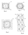
- FIGS. 3 to 5 show further cross-sections through permanent magnet assemblies with iron yoke elements
- FIG. 6 shows a longitudinal section through a permanent magnet assembly with iron yoke elements
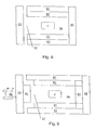
- FIG. 7 shows a longitudinal section through an installation for the plasma processing of continuous material
- FIG. 8 shows a longitudinal section through an installation for the plasma processing of workpieces, with the lid open
- FIG. 9 shows a longitudinal section through an installation for the plasma processing of workpieces, with the plate and the actuating device being open, and
- FIG. 10 shows a longitudinal section through a further embodiment of an installation for the plasma processing of continuous material.
- FIG. 1 shows a section through an installation according to the invention, which, in the following, will be described from the inside to the outside.
- the material to be processed is a continuous material 1 which is surrounded by an external electrode 5 and is guided through a discharge chamber 3 a enclosing the external electrode 5 .
- the discharge chamber is surrounded by a permanent magnet assembly 6 which, in this case, is composed of six permanent magnets 61 .
- the permanent magnet assembly 6 can also be arranged inside the external electrode 5 .
- the permanent magnets 61 are preferably made of an anisotropic material, i.e. they exhibit a preferred orientation. As a matter of fact, such anisotropic permanent magnets 61 can be magnetized more strongly than isotropic ones.
- permanent magnets 61 made of an NdFeB-alloy are well suitable in this case.
- the six permanent magnets 61 thereby essentially form a hexagon.
- Various magnetization directions of the permanent magnets 61 are conceivable.
- a possible variant of the polarization arrangement which produces reasonably homogeneous field ranges in the discharge chamber 3 a is illustrated in FIG. 6 .
- iron yoke elements 62 can be provided which are arranged around the permanent magnet assembly 6 .
- Said iron yoke elements 62 can be firmly connected with fixing means 63 , wherein the fixing means 63 can also be designed so as to be detachable, for instance as screws.
- a mechanically stable arrangement of permanent magnets 61 or of iron yoke elements 62 , respectively, may also be carried out inside a steel pipe.
- FIG. 2 shows, in a longitudinal section, the same installation as in FIG. 1 .
- the differently hatched permanent magnets 61 indicate different magnetization directions of the same.
- a possible magnetization arrangement is illustrated in FIG. 6 .
- FIGS. 3 to 5 show cross-sections through arrangements of permanent magnets 61 comprising iron yoke elements 62 , wherein examples of possible magnetization directions are indicated by the arrows illustrated in the permanent magnets 61 .
- the arrows inside the discharge chamber 3 a symbolize the magnetic lines of force within said chamber.
- other polygonal geometries of arrangements of permanent magnets 61 are conceivable as well.
- a cooling of the high-performance magnet assembly can be provided. Liquid cooling as well as gas cooling, preferably air cooling, are conceivable in this case.
- Strong magnetic fields can also be generated by superconducting electromagnets, which may be provided as a high-performance magnet assembly instead of a permanent magnet assembly 6 .
- Such superconducting electromagnets may also be used for generating magnetic fields of different characteristics inside a discharge chamber 3 a by varying the current strength flowing through them as well as the current direction.
- FIG. 7 and FIG. 10 show exemplary embodiments of an installation for the plasma processing of continuous material 1 .
- the continuous material 1 passes through two discharge chambers 3 a , 3 b toward the postchamber system 2 a . . . 2 k .
- Said system consists of a long postchamber 2 f acting as a gas cooling section as well as of small chambers arranged upstream and downstream, which in turn are interconnected by sluice openings.
- the plurality of sluice openings in combination with an adjustable pressure gradation minimizes the gas flow, the gas consumption and the required pumping capacity.
- the gas flows from the postchamber system 2 into the second discharge chamber 3 b , whereupon the gas flow is split up. A major part is guided through a vacuum pump 7 d , upstream and downstream of which filters 8 are arranged, back into the postchamber 2 f designed as a gas cooling section. A small portion of the gas flows into the first discharge chamber 3 a and reaches the outside via the pump 7 c through the final sluice of the third prechamber 12 e .
- the second discharge chamber 3 b operates with a very clean gas
- the plurality of the evaporations which are released from the continuous material 1 in the first discharge chamber 3 a are mixed with a relatively small amount of the working gas and reach the outside via a vacuum pump 7 c .
- the gas supply 9 to the entire installation is effected via the transverse supply pipe 13 involving an excess pressure that is relatively tiny in comparison with the atmospheric pressure (e.g. 0.1 bar).
- the pressure in the postchamber 2 f designed as a gas cooling section is significantly higher, resulting there in a better cooling capacity of the continuous material 1 .
- a recovery system can be implemented wherein gas is recirculated from a discharge chamber 3 a , 3 b into a prechamber 10 , 11 , 12 and/or postchamber 2 a . . . 2 k having a higher pressure level.
- gas is recirculated from a discharge chamber 3 a , 3 b into a prechamber 10 , 11 , 12 and/or postchamber 2 a . . . 2 k having a higher pressure level.
- helium acts as a working gas.
- a recovery system as illustrated in FIG. 10 has proven its value because of its particular efficiency.
- the continuous material 1 is a stainless steel wire which is calcined, for example, to 1100 degrees Celsius.
- the discharge chambers 3 a , 3 b consist in each case of a stainless steel pipe with a length of 2 m and a diameter of 7 cm, which forms at the same time the vessel wall and the external electrode 5 , as well as of a quartz glass tube 4 which is tightly attached to the external electrode 5 and ensures the electrical insulation of the external electrodes 5 .
- the magnetic field is generated by two tubular permanent magnet assemblies 6 which are arranged concentrically outside of the discharge chambers 3 a , 3 b .
- a cooling liquid is located between the discharge chambers 3 a , 3 b and the permanent magnet assemblies 6 .
- the two permanent magnet assemblies 6 are in each case magnetized in the longitudinal direction and are arranged such that the poles having equal names are oriented against each other. In this way it is achieved that no magnetic field prevails on the plane of symmetry between the two discharge chambers 3 a , 3 b .
- the continuous material 1 can there be “supported” mechanically (e.g. by a guide element 16 , preferably a guide aperture, a lug, a coil or crossed plates) and thus can be prevented from vibrating without a discharge burning to said guide element 16 .
- a direct-current voltage in particular a pulsed direct-current voltage
- a pulsed direct-current voltage is applied as a voltage between the external electrodes 5 of the two discharge chambers 3 a , 3 b and the continuous material 1 , which direct-current voltage is generated in separate energy supply devices (not illustrated).
- a further increase in the energy density can be achieved by pulse discharges, for instance, by means of a square wave signal with an amplitude of, e.g., approx. 300 V and a pulse repetition frequency of approx. 25 kHz. Other values of the amplitude and the pulse repetition frequency may also be chosen, wherein the pulses can partly also have reversed polarities.
- a pulsed direct-current voltage suppresses the undesired formation of arc discharges with a focal point.
- Both the discharge chambers 3 a , 3 b and the continuous-material gas cooling section 2 are liquid-cooled, for example, by means of oil.
- the oil is recirculated by a pump and cools down, via a heat exchanger, to the boiling temperature of the prepurification liquid (water or water with cleaning agents) in the fluid container of a continuous-material prepurification stage, in particular with coarse drying. In this manner, the prepurification liquid is heated and the temperatures of the discharge chambers 3 a , 3 b and those of the gas cooling section 2 f are kept constant.
- a radiation detector which records the thermal radiation of the continuous material 1 and calculates therefrom the surface temperature of the continuous material I is located in the first postchamber 2 a . Furthermore, a liquid cooling stage, in particular a water cooling stage, can be provided after the postchamber system.
- the entire process can be controlled via a regulating or control system 17 , respectively, such as a process control SPS, or also via simple regulating or control systems, respectively, and via valves 18 , which in particular are adjustable and controllable, respectively.
- Gas mixtures may also be used for plasma processing.
- an addition of approx. one to three percent of hydrogen to a helium atmosphere is reasonable in order to make use of the advantages of the good ionizability of hydrogen whereas the predominant portion of helium guarantees operational safety.
- noble gases in general, in particular helium, argon or krypton, with an addition of preferably one to ten, especially one to three, percent of a chemically active, in particular oxidizing or reducing, gas or vapour such as, for example, hydrogen, an alcohol or an alkane, can be used as working gases, for which in each case the corresponding pressures can be adjusted.
- the corresponding optimum pressures are created via vacuum pumps 7 a to 7 d , preferably via cost-saving slide vane rotary pumps, and optionally via filters 8 and valves 18 , whereby, at a given magnetic field, the required pressure for concentrating the plasma stream can be achieved in the area of the magnetic field.
- FIGS. 8 and 9 show an installation for the plasma processing of workpieces 1 ′ in a batch process, using a loading device which comprises in particular a charging opening 22 .
- the charging opening 22 can be sealed in a vacuum-tight manner for example with a nonmagnetic lid 21 .
- a plate 23 comprising at least one permanent magnet 61 may also be arranged, wherein said plate 23 may also comprise an iron yoke element.
- an actuating device 24 can be provided which enables the movement of said plate 23 toward opening or closing, respectively, the charging opening 22 by means of suitable mechanical transmissions such as threaded rods or the like, or by means of hydraulic devices.
Landscapes
- Chemical & Material Sciences (AREA)
- Engineering & Computer Science (AREA)
- Physics & Mathematics (AREA)
- Materials Engineering (AREA)
- Organic Chemistry (AREA)
- Thermal Sciences (AREA)
- Crystallography & Structural Chemistry (AREA)
- Mechanical Engineering (AREA)
- Plasma & Fusion (AREA)
- Metallurgy (AREA)
- Analytical Chemistry (AREA)
- Plasma Technology (AREA)
- Physical Or Chemical Processes And Apparatus (AREA)
- Treatments Of Macromolecular Shaped Articles (AREA)
- Treatment Of Fiber Materials (AREA)
- Drying Of Semiconductors (AREA)
- Sampling And Sample Adjustment (AREA)
- Compounds Of Iron (AREA)
- Pharmaceuticals Containing Other Organic And Inorganic Compounds (AREA)
Applications Claiming Priority (5)
| Application Number | Priority Date | Filing Date | Title |
|---|---|---|---|
| ATA208/2003 | 2003-02-12 | ||
| AT2082003 | 2003-02-12 | ||
| ATA128/2004 | 2004-01-30 | ||
| AT0012804A AT414215B (de) | 2003-02-12 | 2004-01-30 | Anlage zur plasmaprozessierung |
| PCT/AT2004/000043 WO2004073009A2 (de) | 2003-02-12 | 2004-02-09 | Anlage zur magnetfeldbeeinflussten plasmaprozessierung eines endlosmaterials oder werkstücks |
Publications (2)
| Publication Number | Publication Date |
|---|---|
| US20070000881A1 US20070000881A1 (en) | 2007-01-04 |
| US7884302B2 true US7884302B2 (en) | 2011-02-08 |
Family
ID=32869996
Family Applications (1)
| Application Number | Title | Priority Date | Filing Date |
|---|---|---|---|
| US10/545,549 Expired - Fee Related US7884302B2 (en) | 2003-02-12 | 2004-02-09 | Plasma processing installation, influenced by a magnetic field, for processing a continuous material or a workpiece |
Country Status (5)
| Country | Link |
|---|---|
| US (1) | US7884302B2 (de) |
| EP (1) | EP1593142B1 (de) |
| AT (2) | AT414215B (de) |
| DE (1) | DE502004005495D1 (de) |
| WO (1) | WO2004073009A2 (de) |
Families Citing this family (5)
| Publication number | Priority date | Publication date | Assignee | Title |
|---|---|---|---|---|
| DE102005044362A1 (de) * | 2005-09-09 | 2007-03-15 | Newfrey Llc, Newark | Fügewerkzeug und Verfahren zum Fügen eines Elementes auf ein Bauteil |
| AT502351A1 (de) * | 2005-09-12 | 2007-03-15 | Ziger Peter | Anlage zur plasmaprozessierung von endlosmaterial |
| AT503377B1 (de) * | 2006-02-02 | 2008-09-15 | Eiselt Primoz | Verfahren und vorrichtung zur plasmabehandlung von materialien |
| PL2801625T3 (pl) | 2010-07-02 | 2018-06-29 | University Of Virginia Patent Foundation | Molekularne, genetyczne podejście do leczenia i diagnozy uzależnienia od alkoholu i leków |
| EP3045173A3 (de) | 2011-09-09 | 2016-09-14 | The University of Virginia Patent Foundation | Molekularer genetischer ansatz zur behandlung und diagnose von alkohol- und drogenabhängigkeit |
Citations (24)
| Publication number | Priority date | Publication date | Assignee | Title |
|---|---|---|---|---|
| US3211886A (en) | 1963-05-06 | 1965-10-12 | Gen Electric | Arc-cleaning and arc-plasma generating apparatus |
| US3533358A (en) * | 1967-06-01 | 1970-10-13 | Creusot Forges Ateliers | Device for compensating automatically for variations in the tension on and length of cables in appliances for transferring loads between two moving objects by cables |
| US3728246A (en) * | 1970-01-22 | 1973-04-17 | E Barkhudarov | Device for applying thin films to articles |
| DE2157606A1 (de) | 1971-11-20 | 1973-05-24 | Max Planck Gesellschaft | Verfahren und einrichtung zur waermebehandlung eines materials durch ein bogenentladungsplasma |
| US3884793A (en) | 1971-09-07 | 1975-05-20 | Telic Corp | Electrode type glow discharge apparatus |
| JPS5741318A (en) | 1980-08-27 | 1982-03-08 | Nippon Steel Corp | Circulating and supplying device for gaseous atmosphere of heat treatment furnace |
| US4318533A (en) * | 1978-07-25 | 1982-03-09 | Walter Port | Apparatus for maintaining tension on a tension cable |
| DE3041095A1 (de) | 1980-10-31 | 1982-05-13 | Vsesojuznyj naučno-issledovatel'skij institut Metiznoj promyšlennosti VNIIMETIZ, Magnitogorsk, Čeljabinskaja oblast' | Lichtbogeneinrichtung zur oberflaechenbearbeitung von langen werkstuecken |
| US4543470A (en) * | 1983-03-15 | 1985-09-24 | Skf Steel Engineering Ab | Means for electrically heating gases |
| EP0313154A1 (de) | 1987-10-21 | 1989-04-26 | N.V. Bekaert S.A. | Verfahren und Vorrichtung zur Reinigung von langgestreckten metallischen Substraten, Substrate gereinigt mit diesem Verfahren, und Gegenstände aus polymerem Material, verstärkt mit diesen Substraten |
| US4842704A (en) | 1987-07-29 | 1989-06-27 | Collins George J | Magnetron deposition of ceramic oxide-superconductor thin films |
| US4950450A (en) | 1988-07-21 | 1990-08-21 | Eastman Kodak Company | Neodymium iron boron magnets in a hot consolidation process of making the same |
| US4950956A (en) | 1986-10-08 | 1990-08-21 | Anelva Corporation | Plasma processing apparatus |
| US5234560A (en) | 1989-08-14 | 1993-08-10 | Hauzer Holdings Bv | Method and device for sputtering of films |
| DE4211167A1 (de) | 1992-03-31 | 1993-10-07 | Thaelmann Schwermaschbau Veb | Verfahren und Vorrichtung zur kontinuierlichen thermischen Oberflächenbehandlung stab- bzw. strangförmiger Materialien mit metallischer Oberfläche |
| US5317006A (en) | 1989-06-15 | 1994-05-31 | Microelectronics And Computer Technology Corporation | Cylindrical magnetron sputtering system |
| US5490910A (en) | 1992-03-09 | 1996-02-13 | Tulip Memory Systems, Inc. | Circularly symmetric sputtering apparatus with hollow-cathode plasma devices |
| FR2774400A1 (fr) | 1998-02-04 | 1999-08-06 | Physiques Et Chimiques | Dispositif electrique pour degraissage, decapage ou passivation plasmachimique de metaux |
| EP0966021A2 (de) | 1998-06-19 | 1999-12-22 | Leybold Systems GmbH | Vorrichtung zum Beschichten von Substraten in einer Vakuumkammer |
| EP0981150A2 (de) | 1998-08-14 | 2000-02-23 | Leybold Systems GmbH | Vorrichtung zum Beschichten von Substraten mit dünnen Schichten |
| DE19907911A1 (de) | 1999-02-24 | 2000-09-21 | Mag Masch App | Vorrichtung und Verfahren zur Behandlung von elektrisch leitfähigem Endlosmaterial |
| DE10001381A1 (de) | 2000-01-14 | 2001-07-19 | Hauzer Techno Coating Europ B | PVD-Verfahren zur Herstellung einer gefärbten, gegenüber Fingerabdrücken unempfindlichen Beschichtung auf Gegenständen sowie Gegenstände mit einer solchen Beschichtung |
| EP1178134A1 (de) | 2000-08-04 | 2002-02-06 | Cold Plasma Applications C.P.A. | Pasma-Verfahren und -Vorrichtung zur Durchlaufbehandlung metallischer Gegenstände |
| US6974501B1 (en) * | 1999-11-18 | 2005-12-13 | American Superconductor Corporation | Multi-layer articles and methods of making same |
-
2004
- 2004-01-30 AT AT0012804A patent/AT414215B/de not_active IP Right Cessation
- 2004-02-09 US US10/545,549 patent/US7884302B2/en not_active Expired - Fee Related
- 2004-02-09 DE DE502004005495T patent/DE502004005495D1/de not_active Expired - Lifetime
- 2004-02-09 AT AT04709164T patent/ATE378689T1/de active
- 2004-02-09 EP EP04709164A patent/EP1593142B1/de not_active Expired - Lifetime
- 2004-02-09 WO PCT/AT2004/000043 patent/WO2004073009A2/de not_active Ceased
Patent Citations (25)
| Publication number | Priority date | Publication date | Assignee | Title |
|---|---|---|---|---|
| US3211886A (en) | 1963-05-06 | 1965-10-12 | Gen Electric | Arc-cleaning and arc-plasma generating apparatus |
| US3533358A (en) * | 1967-06-01 | 1970-10-13 | Creusot Forges Ateliers | Device for compensating automatically for variations in the tension on and length of cables in appliances for transferring loads between two moving objects by cables |
| US3728246A (en) * | 1970-01-22 | 1973-04-17 | E Barkhudarov | Device for applying thin films to articles |
| US3884793A (en) | 1971-09-07 | 1975-05-20 | Telic Corp | Electrode type glow discharge apparatus |
| DE2157606A1 (de) | 1971-11-20 | 1973-05-24 | Max Planck Gesellschaft | Verfahren und einrichtung zur waermebehandlung eines materials durch ein bogenentladungsplasma |
| US4318533A (en) * | 1978-07-25 | 1982-03-09 | Walter Port | Apparatus for maintaining tension on a tension cable |
| JPS5741318A (en) | 1980-08-27 | 1982-03-08 | Nippon Steel Corp | Circulating and supplying device for gaseous atmosphere of heat treatment furnace |
| DE3041095A1 (de) | 1980-10-31 | 1982-05-13 | Vsesojuznyj naučno-issledovatel'skij institut Metiznoj promyšlennosti VNIIMETIZ, Magnitogorsk, Čeljabinskaja oblast' | Lichtbogeneinrichtung zur oberflaechenbearbeitung von langen werkstuecken |
| US4543470A (en) * | 1983-03-15 | 1985-09-24 | Skf Steel Engineering Ab | Means for electrically heating gases |
| US4950956A (en) | 1986-10-08 | 1990-08-21 | Anelva Corporation | Plasma processing apparatus |
| US4842704A (en) | 1987-07-29 | 1989-06-27 | Collins George J | Magnetron deposition of ceramic oxide-superconductor thin films |
| EP0313154A1 (de) | 1987-10-21 | 1989-04-26 | N.V. Bekaert S.A. | Verfahren und Vorrichtung zur Reinigung von langgestreckten metallischen Substraten, Substrate gereinigt mit diesem Verfahren, und Gegenstände aus polymerem Material, verstärkt mit diesen Substraten |
| US4950450A (en) | 1988-07-21 | 1990-08-21 | Eastman Kodak Company | Neodymium iron boron magnets in a hot consolidation process of making the same |
| US5317006A (en) | 1989-06-15 | 1994-05-31 | Microelectronics And Computer Technology Corporation | Cylindrical magnetron sputtering system |
| US5234560A (en) | 1989-08-14 | 1993-08-10 | Hauzer Holdings Bv | Method and device for sputtering of films |
| US5490910A (en) | 1992-03-09 | 1996-02-13 | Tulip Memory Systems, Inc. | Circularly symmetric sputtering apparatus with hollow-cathode plasma devices |
| DE4211167A1 (de) | 1992-03-31 | 1993-10-07 | Thaelmann Schwermaschbau Veb | Verfahren und Vorrichtung zur kontinuierlichen thermischen Oberflächenbehandlung stab- bzw. strangförmiger Materialien mit metallischer Oberfläche |
| FR2774400A1 (fr) | 1998-02-04 | 1999-08-06 | Physiques Et Chimiques | Dispositif electrique pour degraissage, decapage ou passivation plasmachimique de metaux |
| EP0966021A2 (de) | 1998-06-19 | 1999-12-22 | Leybold Systems GmbH | Vorrichtung zum Beschichten von Substraten in einer Vakuumkammer |
| EP0981150A2 (de) | 1998-08-14 | 2000-02-23 | Leybold Systems GmbH | Vorrichtung zum Beschichten von Substraten mit dünnen Schichten |
| DE19907911A1 (de) | 1999-02-24 | 2000-09-21 | Mag Masch App | Vorrichtung und Verfahren zur Behandlung von elektrisch leitfähigem Endlosmaterial |
| US6471920B2 (en) * | 1999-02-24 | 2002-10-29 | Mag Maschinen Und Apparatebau Aktiengesellschaft | Apparatus and method for treatment of electrically conductive continuous material |
| US6974501B1 (en) * | 1999-11-18 | 2005-12-13 | American Superconductor Corporation | Multi-layer articles and methods of making same |
| DE10001381A1 (de) | 2000-01-14 | 2001-07-19 | Hauzer Techno Coating Europ B | PVD-Verfahren zur Herstellung einer gefärbten, gegenüber Fingerabdrücken unempfindlichen Beschichtung auf Gegenständen sowie Gegenstände mit einer solchen Beschichtung |
| EP1178134A1 (de) | 2000-08-04 | 2002-02-06 | Cold Plasma Applications C.P.A. | Pasma-Verfahren und -Vorrichtung zur Durchlaufbehandlung metallischer Gegenstände |
Also Published As
| Publication number | Publication date |
|---|---|
| EP1593142A2 (de) | 2005-11-09 |
| WO2004073009A2 (de) | 2004-08-26 |
| EP1593142B1 (de) | 2007-11-14 |
| US20070000881A1 (en) | 2007-01-04 |
| AT414215B (de) | 2006-10-15 |
| ATE378689T1 (de) | 2007-11-15 |
| WO2004073009A3 (de) | 2005-02-03 |
| ATA1282004A (de) | 2006-01-15 |
| DE502004005495D1 (de) | 2007-12-27 |
Similar Documents
| Publication | Publication Date | Title |
|---|---|---|
| US5198677A (en) | Production of N+ ions from a multicusp ion beam apparatus | |
| EP0046154B1 (de) | Vorrichtung zur Beschichtung von Substraten mittels Hochleistungskathodenzerstäubung sowie Zerstäuberkathode für diese Vorrichtung | |
| US4407713A (en) | Cylindrical magnetron sputtering cathode and apparatus | |
| US5646476A (en) | Channel ion source | |
| JP3652702B2 (ja) | プラズマ処理用線形アーク放電発生装置 | |
| EP1089319B1 (de) | Gleichmässige Gasverteilung in einer grossflächige Plasma-Behandlungs-Vorrichtung | |
| US20020153103A1 (en) | Plasma treatment apparatus | |
| US20040219737A1 (en) | Method and apparatus for processing a workpiece with a plasma | |
| US4769101A (en) | Apparatus for surface-treating workpieces | |
| JP2009128276A (ja) | 電離真空装置 | |
| US4847476A (en) | Ion source device | |
| US4739170A (en) | Plasma generator | |
| KR101688338B1 (ko) | 플라스마 처리 장치 및 플라스마 처리 방법 | |
| US7884302B2 (en) | Plasma processing installation, influenced by a magnetic field, for processing a continuous material or a workpiece | |
| US20070034501A1 (en) | Cathode-arc source of metal/carbon plasma with filtration | |
| US6525480B1 (en) | Low power, linear geometry hall plasma source with an open electron drift | |
| RU2402098C2 (ru) | Установка для плазменной обработки бесконечного материала | |
| US3452249A (en) | Method and apparatus for containing a plasma produced by opposed electrodes | |
| JPH10326695A (ja) | 圧力勾配型電子ビーム励起プラズマ発生装置 | |
| KR20230142608A (ko) | 스퍼터링 장치 | |
| JP5798697B2 (ja) | 真空筐体内においてコールドプラズマを生成する装置、熱化学処理および窒化に対する該装置の使用 | |
| JP2009272127A (ja) | プラズマ発生装置及びプラズマ処理装置 | |
| US3755710A (en) | Gas plasma device | |
| JP2008218602A (ja) | 蒸気レーザ装置 | |
| EP1176857A1 (de) | Gleichstrom-Plasmaerzeuger zur Erzeugung eines nicht-lokalen, nicht im thermodynamischen Gleichgewicht, Hochdruck-Plasmas |
Legal Events
| Date | Code | Title | Description |
|---|---|---|---|
| AS | Assignment |
Owner name: ZIGER, PETER, AUSTRIA Free format text: ASSIGNMENT OF ASSIGNORS INTEREST;ASSIGNORS:ZIGER, PETER;JAGER, HELMUT;NEUREITER, CHRISTIAN;REEL/FRAME:018126/0029;SIGNING DATES FROM 20050921 TO 20050922 Owner name: ZIGER, PETER, AUSTRIA Free format text: ASSIGNMENT OF ASSIGNORS INTEREST;ASSIGNORS:ZIGER, PETER;JAGER, HELMUT;NEUREITER, CHRISTIAN;SIGNING DATES FROM 20050921 TO 20050922;REEL/FRAME:018126/0029 |
|
| REMI | Maintenance fee reminder mailed | ||
| LAPS | Lapse for failure to pay maintenance fees | ||
| STCH | Information on status: patent discontinuation |
Free format text: PATENT EXPIRED DUE TO NONPAYMENT OF MAINTENANCE FEES UNDER 37 CFR 1.362 |
|
| STCH | Information on status: patent discontinuation |
Free format text: PATENT EXPIRED DUE TO NONPAYMENT OF MAINTENANCE FEES UNDER 37 CFR 1.362 |
|
| FP | Lapsed due to failure to pay maintenance fee |
Effective date: 20150208 |