US7887196B2 - Projection system and method for operating a projection system to compensate for overshoot sequence - Google Patents
Projection system and method for operating a projection system to compensate for overshoot sequence Download PDFInfo
- Publication number
- US7887196B2 US7887196B2 US11/912,343 US91234306A US7887196B2 US 7887196 B2 US7887196 B2 US 7887196B2 US 91234306 A US91234306 A US 91234306A US 7887196 B2 US7887196 B2 US 7887196B2
- Authority
- US
- United States
- Prior art keywords
- high pressure
- pressure discharge
- discharge lamp
- current
- frequency
- Prior art date
- Legal status (The legal status is an assumption and is not a legal conclusion. Google has not performed a legal analysis and makes no representation as to the accuracy of the status listed.)
- Expired - Fee Related, expires
Links
Images



Classifications
-
- H—ELECTRICITY
- H04—ELECTRIC COMMUNICATION TECHNIQUE
- H04N—PICTORIAL COMMUNICATION, e.g. TELEVISION
- H04N9/00—Details of colour television systems
- H04N9/12—Picture reproducers
- H04N9/31—Projection devices for colour picture display, e.g. using electronic spatial light modulators [ESLM]
- H04N9/3102—Projection devices for colour picture display, e.g. using electronic spatial light modulators [ESLM] using two-dimensional electronic spatial light modulators
- H04N9/3111—Projection devices for colour picture display, e.g. using electronic spatial light modulators [ESLM] using two-dimensional electronic spatial light modulators for displaying the colours sequentially, e.g. by using sequentially activated light sources
- H04N9/3114—Projection devices for colour picture display, e.g. using electronic spatial light modulators [ESLM] using two-dimensional electronic spatial light modulators for displaying the colours sequentially, e.g. by using sequentially activated light sources by using a sequential colour filter producing one colour at a time
-
- H—ELECTRICITY
- H04—ELECTRIC COMMUNICATION TECHNIQUE
- H04N—PICTORIAL COMMUNICATION, e.g. TELEVISION
- H04N9/00—Details of colour television systems
- H04N9/12—Picture reproducers
- H04N9/31—Projection devices for colour picture display, e.g. using electronic spatial light modulators [ESLM]
- H04N9/3141—Constructional details thereof
- H04N9/315—Modulator illumination systems
- H04N9/3155—Modulator illumination systems for controlling the light source
-
- H—ELECTRICITY
- H04—ELECTRIC COMMUNICATION TECHNIQUE
- H04N—PICTORIAL COMMUNICATION, e.g. TELEVISION
- H04N9/00—Details of colour television systems
- H04N9/64—Circuits for processing colour signals
-
- H—ELECTRICITY
- H05—ELECTRIC TECHNIQUES NOT OTHERWISE PROVIDED FOR
- H05B—ELECTRIC HEATING; ELECTRIC LIGHT SOURCES NOT OTHERWISE PROVIDED FOR; CIRCUIT ARRANGEMENTS FOR ELECTRIC LIGHT SOURCES, IN GENERAL
- H05B41/00—Circuit arrangements or apparatus for igniting or operating discharge lamps
- H05B41/14—Circuit arrangements
- H05B41/26—Circuit arrangements in which the lamp is fed by power derived from DC by means of a converter, e.g. by high-voltage DC
- H05B41/28—Circuit arrangements in which the lamp is fed by power derived from DC by means of a converter, e.g. by high-voltage DC using static converters
- H05B41/288—Circuit arrangements in which the lamp is fed by power derived from DC by means of a converter, e.g. by high-voltage DC using static converters with semiconductor devices and specially adapted for lamps without preheating electrodes, e.g. for high-intensity discharge lamps, high-pressure mercury or sodium lamps or low-pressure sodium lamps
- H05B41/2881—Load circuits; Control thereof
- H05B41/2882—Load circuits; Control thereof the control resulting from an action on the static converter
- H05B41/2883—Load circuits; Control thereof the control resulting from an action on the static converter the controlled element being a DC/AC converter in the final stage, e.g. by harmonic mode starting
-
- H—ELECTRICITY
- H05—ELECTRIC TECHNIQUES NOT OTHERWISE PROVIDED FOR
- H05B—ELECTRIC HEATING; ELECTRIC LIGHT SOURCES NOT OTHERWISE PROVIDED FOR; CIRCUIT ARRANGEMENTS FOR ELECTRIC LIGHT SOURCES, IN GENERAL
- H05B41/00—Circuit arrangements or apparatus for igniting or operating discharge lamps
- H05B41/14—Circuit arrangements
- H05B41/26—Circuit arrangements in which the lamp is fed by power derived from DC by means of a converter, e.g. by high-voltage DC
- H05B41/28—Circuit arrangements in which the lamp is fed by power derived from DC by means of a converter, e.g. by high-voltage DC using static converters
- H05B41/288—Circuit arrangements in which the lamp is fed by power derived from DC by means of a converter, e.g. by high-voltage DC using static converters with semiconductor devices and specially adapted for lamps without preheating electrodes, e.g. for high-intensity discharge lamps, high-pressure mercury or sodium lamps or low-pressure sodium lamps
- H05B41/2885—Static converters especially adapted therefor; Control thereof
- H05B41/2887—Static converters especially adapted therefor; Control thereof characterised by a controllable bridge in the final stage
-
- Y—GENERAL TAGGING OF NEW TECHNOLOGICAL DEVELOPMENTS; GENERAL TAGGING OF CROSS-SECTIONAL TECHNOLOGIES SPANNING OVER SEVERAL SECTIONS OF THE IPC; TECHNICAL SUBJECTS COVERED BY FORMER USPC CROSS-REFERENCE ART COLLECTIONS [XRACs] AND DIGESTS
- Y02—TECHNOLOGIES OR APPLICATIONS FOR MITIGATION OR ADAPTATION AGAINST CLIMATE CHANGE
- Y02B—CLIMATE CHANGE MITIGATION TECHNOLOGIES RELATED TO BUILDINGS, e.g. HOUSING, HOUSE APPLIANCES OR RELATED END-USER APPLICATIONS
- Y02B20/00—Energy efficient lighting technologies, e.g. halogen lamps or gas discharge lamps
Definitions
- the invention relates to a projection system having a high pressure discharge lamp, preferably a high performance discharge lamp, for example a UHP (ultra-high performance) lamp, and a display device with a control device which switches the display device in a time-modulated fashion so that a brightness level in an image is represented by the total length of a number of light switch-on phases within a particular image cycle.
- the invention also relates to a method for operating a projection system, and to a lamp driver for a high pressure discharge lamp in such a projection system.
- the key component of this system is a display device in the form of a chip, on which a number of minute mobile mirrors is applied as individual display elements—one mirror per image point to be represented. These mirrors are exposed to the light from the high pressure discharge lamp.
- the associated mirror is tilted so that the light is reflected toward the projection surface or away from it to an absorber.
- the individual mirrors of this “mirror array” consequently form a network with which arbitrary image patterns can be generated and, for example, video images can be reproduced.
- each display element of the display device is driven so that, overall, light strikes the relevant image point of the projection surface over a particular time fraction of the image cycle, and not in the remaining time fraction.
- the amount of light is integrated in an observer's eye over an image cycle, so that the relevant image point appears brighter or darker. If the light is turned off fully during an image cycle, i.e. a light switch-off phase occupies the entire image cycle then the relevant image point appears black. If the light is turned on over the entire length of the image cycle, however, then the relevant pixel has the highest brightness level. Since the brightness in such systems is controlled via the time sequential switching, i.e. the length and number of the light switch-on and switch-off phases within an image cycle, it is necessary that the light intensity to which the display is exposed should be as constant as possible not only spatially but also temporally. This is because if the light intensity were to change within an image cycle, then the brightness level would be determined not only by the total length of the light switch-on phases and light switch-off phases but also by the chronological position of the individual light switch-on phases within the image cycle.
- a light source which as far as possible emits a constant luminous power (a constant light flux), i.e. always the same amount of light.
- high pressure discharge lamps as lamps in such projection systems, preferably high intensity discharge lamps (HID lamps).
- these lamps are operated with a low-frequency square-wave alternating current so that the current direction between the electrodes switches over constantly.
- the lamp is in this case generally driven by a special lamp driver, which converts the DC current provided by a DC voltage source into the square-wave alternating current required for the lamp with the appropriate pulse shape.
- a color filter is arranged between the lamp and the display device, usually in the form of a so-called color wheel which alternates the color at a particular frequency.
- spokes in analogy with the spokes of a wheel—the color is undefined.
- the square-wave alternating current could therefore in principle be synchronized with the driving of the color filter so that the overshoot sequence always lies within such a spoke time.
- a current pulse which temporarily increases the operating current before the zero crossing, should be superimposed on the operating current as close as possible before a current zero crossing.
- Such a stabilization pulse is also generally referred to as an anti-flatter pulse.
- Such an anti-flatter pulse of course also leads to corresponding light fluctuations in the lamp.
- EP 1 154 652 A2 proposes that the lamp driver and the controlling of the color filter should be synchronized so that this anti-flatter pulse lies within a spoke time and cannot lead to disturbance of the brightness levels in the image. Since the anti-flatter pulse lies immediately before the zero crossing of the current and the overshoot sequence lies immediately after the zero crossing, these regions directly follow each other inside the time profile of the current. Unfortunately, however, the spoke time is generally at best long enough for the anti-flatter pulse to be accommodated in this time span. The overshoot sequence therefore necessarily comes after a spoke time, i.e. at the start of an image cycle. In principle, it would admittedly be possible to extend the spoke time artificially by appropriate driving of the display. This solution, however, leads to a great loss of light which degrades the overall image quality.
- this problem is therefore countered by designing the driving of the display elements so that the system reacts as insensitively as possible to the overshoot sequence.
- the individual switch-on or switch-off times within an image cycle may be selected so that as long as possible a switch-off phase lies directly at the start of an image cycle and the overshoot sequence is therefore substantially blocked out.
- the high pressure discharge lamp of the projection system is operated via a lamp driver with an essentially square-wave (low-frequency) alternating current so that the overshoot sequence, which occurs in the alternating current after a current zero crossing has a frequency so high that for each possible brightness level at least one full period of the overshoot sequence lies essentially within a light switch-on or switch-off phase following the zero crossing.
- a lamp driver with an essentially square-wave (low-frequency) alternating current so that the overshoot sequence, which occurs in the alternating current after a current zero crossing has a frequency so high that for each possible brightness level at least one full period of the overshoot sequence lies essentially within a light switch-on or switch-off phase following the zero crossing.
- an “essentially square-wave alternating current” in the context of this invention moreover generally means an alternating current with a current profile which—apart from customary tolerances and current pulses deliberately superimposed for particular effects—has a substantially constant profile over time and a sufficiently fast polarity change. That is to say besides a customarily used square-wave alternating current, this also includes for example a trapezoidal alternating current or the like, the edges of which are steep enough for use in a corresponding projection system.
- the current pulses deliberately superimposed for particular effects may, for example, be the aforementioned anti-flatter pulse or in particular square-wave pulses which, for example, extend over the length of a particular color segment in order to increase the intensity of this color compared to other colors.
- the object is furthermore achieved by a projection system as claimed in claim 7 .
- a projection system Besides a high pressure discharge lamp and a conventional display device with a control device, which switches the display device in a time-modulated fashion so that a brightness level in an image is represented by the total length of a number of light switch-on phases within a particular image cycle, such a projection system according to the invention requires above all a lamp driver which is designed such that the high pressure discharge lamp of the projection system is operated with an essentially square-wave alternating current so that the overshoot sequence, which occurs in the alternating current after a current zero crossing during operation of the high pressure discharge lamp, has a frequency so high that for each possible brightness level at least one full period of the overshoot sequence lies essentially within a light switch-on or switch-off phase following the zero crossing.
- the frequency should be so high that if possible a multiplicity of full periods of the overshoot sequence lies within a switch-on or switch-off phase. In principle, however, in the extreme case it is sufficient for such averaging out of the effect of the overshoot sequence that one full period should lie within such a switch-on or switch-off phase.
- the frequency of the overshoot sequence is greater than or equal to 7.5 kHz, so that it is preferable to ensure that the frequency reaches this value.
- a frequency which is greater than or equal to 9.5 kHz should be reached, since the effect of the overshoot sequence can no longer be discerned by the observer above this frequency in the systems tested so far.
- a brightness level in the image is conventionally represented digitally by a sequence of bits with different values within an image cycle.
- the bits are respectively defined by the length of a light switching phase in the relevant image cycle.
- the bits may also be decomposed into a plurality of switching sub-phases.
- the frequency in a more particularly preferred embodiment should be selected so that at least one full period of the overshoot sequence lies essentially within the switching phase of a least significant bit (conventionally called LSB).
- a particularly preferred lamp driver constructed according to the invention for a high pressure discharge lamp in a projection system according to the invention has a circuit arrangement which converts a direct current tapped from the DC voltage source into an essentially square-wave alternating current for the high pressure discharge lamp with a frequency of between 40 Hz and 2 kHz, preferably between 45 and 150 Hz.
- the circuit arrangement is in this case designed so that an overshoot sequence, which occurs in the alternating current after a current zero crossing during operation of the high pressure discharge lamp, has a frequency greater than or equal to 7.5 kHz, preferably greater than or equal to 9.5 kHz.
- the circuit arrangement has a switching converter which sets the amplitude of the operating current of the high pressure discharge lamp, i.e. it imposes the current profile, and a commutator circuit which commutates the current direction, then essentially the inductances in the commutator circuit and capacitances in the switching converter are preferably dimensioned so that the frequency of the overshoot sequence corresponds to the aforementioned values.
- the inductance of the lamp itself should also be taken into account so that the inductances acting in the commutator circuit must be designed in accordance with the other components.
- FIG. 1 shows a schematic representation of an exemplary embodiment of a projection system
- FIG. 2 shows a schematic representation to explain the time-sequential representation of brightness levels within an image
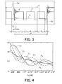
- FIG. 3 shows a schematic representation of the lamp operating current, the resulting light flux and the synchronization clock for driving various components of the projection system
- FIG. 4 shows a diagram which represents the relative error in the light flux against the frequency of the overshoot sequence for various switching times
- FIG. 5 shows a basic circuit diagram of an exemplary embodiment of a lamp driver according to the invention.
- FIG. 1 shows a typical DLP® projection system 1 .
- This system has a high pressure discharge lamp, preferably a so-called UHP (ultra-high performance) lamp, arranged in a reflector 3 .
- the lamp 2 is supplied with the required square-wave voltage by a driver 10 .
- the light emitted by the lamp 2 is focused in the direction of a converging lens 5 by the reflector 3 .
- the color wheel 4 is preferably positioned as accurately as possible at the focal point lying between the reflector 3 and the converging lens 5 so that the light spot on the color wheel 4 is as small as possible.
- the converging lens 5 ensures that a display device, here a so-called DMD (digital mirror device), located behind the converging lens 5 is illuminated as well as possible.
- a display device here a so-called DMD (digital mirror device)
- DMD digital mirror device
- the color wheel 4 here has three segments with the colors red r, green g and blue b.
- This color wheel 4 rotates one or more times about its own axis within an image cycle VT, so as to successively generate a monochrome blue image, a monochrome red image and a monochrome green image which combine to form a color image owing to the inertia of the observer's eye.
- a color wheel with three segments it is of course also possible to use other color wheels, for example color wheels with four segments (a red segment, a green segment, a blue segment and a white segment) or with six segments, in which two green, two red and two blue segments respectively lie opposite each other.
- the latter variant has the advantage that the color wheel only has to rotate with half the frequency.
- further different color segments may also be introduced, for example yellow, cyan, etc.
- a control device 9 drives the display device 6 (also referred to below as the “display” for brevity), the color wheel 4 and the lamp driver 10 and thus ensures the synchronization, to be described in more detail below, of these components 6 , 4 , 10 .
- the control device 9 may receive a video signal V which contains video data that are to be represented by the projection system 1 .
- the control device 9 may also consist of a plurality of control sub-devices.
- a separate control device may also be provided in order to drive the display elements 7 of the display 6 , and this may in particular also be arranged on a circuit board with the DMD chip.
- the complete control device is integrated in one component, for example with the DMD chip, and to send the synchronization commands for the other components from there. It is furthermore possible for the other components, such as the color wheel or lamp driver, to have their own control devices which in turn transmit synchronization commands to the other components. What is essential in the end is merely that the components are synchronized with one another in the required way so that the intended image is generated on the projection surface F.
- FIG. 2 shows a graphical representation to explain how different brightness levels B 1 , B 2 , B 3 , B 4 , B 5 , B 6 can be represented in the image IM by time-modulated switching of the individual mirrors 7 .
- a DMD chip with 6 ⁇ 6 individual mirrors 7 is represented here by way of example.
- the projection objective 8 the light rays reflected by the individual mirrors 7 are represented as image pixels within the image IM on the projection surface F.
- FIG. 2 shows a graphical representation to explain how different brightness levels B 1 , B 2 , B 3 , B 4 , B 5 , B 6 can be represented in the image IM by time-modulated switching of the individual mirrors 7 .
- a DMD chip with 6 ⁇ 6 individual mirrors 7 is represented here by way of example.
- the projection objective 8 the light rays reflected by the individual mirrors 7 are represented as image pixels within the image IM on the projection surface F.
- FIG. 2 shows a graphical representation to explain how different brightness levels B 1
- the time profile within an image cycle VT is represented between the projection objective 8 and the projection surface F.
- the example represented is based on a simplified version in which 16 different brightness levels can be represented digitally with the aid of four bits.
- this is done by respectively defining the bits by the total length of a particular light switching phase in the relevant image cycle VT, i.e. the value of a bit depends on how long the light strikes the respective image pixel on the projection surface F during an image cycle VT, i.e. is switched on.
- Examples of bit sequences which may be set from top to bottom for the individual mirrors 7 in the central column of the DMD chip 6 , are shown below the DMD chip 6 (in FIG. 2 ).
- the top mirror is accordingly driven in an image cycle VT so that the corresponding image pixel has the lowest brightness level B 6 .
- This mirror is accordingly driven with the value 0, which corresponds in binary to the number [0000].
- the mirror lying below is intended to represent the next brightness level up B 5 , and is therefore driven with the binary number [0001]. That is to say this mirror is switched so that the light shines only during a time span which corresponds to the least significant bit, and is otherwise switched off. When there are 16 levels in all, this time span corresponds to one 16 th of the total image cycle VT, which is correspondingly represented in FIG. 2 .
- the third mirror down is intended to represent the next brightness level up and therefore receives the binary value [0010], to which end this mirror is switched on for a time period of one 8 th of the image cycle VT and switched off for the rest of the time.
- 16 brightness levels can be arbitrarily represented digitally, with the mirror reflecting the light onto the relevant pixel on the projection plane throughout the image cycle VT in the case of the highest brightness level B 1 . This is represented in FIG. 2 for the bottom mirror and the associated top image pixel in the relevant column of the image IM.
- a signal is now to be represented by discrete digital values in this way, then the resolution is set by the number of possible levels.
- the standard for modern projection systems is an 8 bit representation. This corresponds to 256 brightness levels in all. In general, it is necessary for the light flux to be so constant that the accuracy of the representation is at least better than or equal to the lowest brightness levels. If errors greater than the lowest representable level occur in the representation, there may sometimes no longer be constant function. This means that a value which should actually be minimally brighter is darker because of possible errors in the consistency of the light flux. Such errors are unfortunately particularly perceptible in images since they lead to stripes in slow color profiles.
- the accuracy of the representation must be at least better than or equal to the lowest representable level.
- FIG. 3 shows a schematic representation of the curve profiles of the various parameters within the projection system against time during an image cycle VT.
- the curve S shows the profile of the synchronization signal, which is used to synchronize the lamp driver 10 , the color wheel 4 and the display 6 with one another.
- the curve I L shows the profile of the lamp current.
- a square-wave alternating current is employed here, the half-period of which corresponds to the length of an image cycle VT. This means that with an image frequency of 60 Hz, for example, the square-wave alternating current of the lamp driver 10 has a frequency of 30 Hz.
- the lamp driver 10 shapes the current so that a current pulse I AF , the so-called anti-flatter pulse, is set immediately before switchover of the current direction. As explained in the introduction, this ensures that the arc discharges remain as stable as possible and the durability of the electrodes is extended. The undesired overshoot sequence O then occurs immediately after the zero crossing.
- the curve Z shows the profile of the light intensity on the projection surface F (assuming that the light has not in the meantime been tilted away with the aid of the mirror).
- the overshoot sequence O in the current profile can be seen clearly in the light flux profile Z. This means that the overshoot sequence also occurs almost unchanged in the light flux profile Z.
- the light flux profile Z furthermore shows the spoke times s in which the light is blocked during the color change.
- the various color phases red r, green g and blue b lie between spoke times s.
- the lamp driver 10 and the color wheel 4 are synchronized so that the anti-flatter pulse I AF in the current profile I L coincides exactly with a spoke time S.
- This means that the overshoot sequence O following the anti-flatter pulse I AF lies after the zero crossing inside the image cycle VT.
- it is therefore necessary to ensure that the error generated by the overshoot sequence O is as small as possible. This is done according to the invention by increasing the frequency of the overshoot sequence O to such an extent that at least one full period P lies within a coherent switch-on or switch-off phase t S of the display following the zero crossing, as indicated in FIG. 3 .
- the light flux profile L(t) during the overshoot sequence can be mathematically described as follows:
- L ⁇ ( t ) 1 + A ring ⁇ e - ( t ⁇ ring ) ⁇ sin ( 2 ⁇ ⁇ ⁇ f ring ⁇ t - ⁇ 6 ) ( 2 )
- f ring is the frequency
- a ring is the amplitude
- ⁇ ring is the time constant of the decay of the overshoot sequence.
- the deviation in the light flux ⁇ L can therefore be calculated as a function of the frequency f ring of the overshoot sequence and according to the length of the switching phase t S placed after the zero crossing:
- Equation (3) for the deviation ⁇ L is represented in FIG. 4 as a function of the frequency f ring of the overshoot sequence for various switching times TS.
- the amount of light of the least significant bit would then be 1,000 ⁇ s % according to the above calculations for Equation (1).
- the curves in FIG. 4 respectively represent the error against the frequency of the overshoot sequence for switching times t S of between 90 ⁇ s and 700 ⁇ s, with the function corresponding to
- the curves in FIG. 4 are of course also dependent on the amplitude of the overshoot sequence.
- a relatively high value was assumed to calculate the curves in FIG. 4 , for which the amplitude of the overshoot frequency may be up to 40% of the average “normal” current amplitude (instead of the values ⁇ 10% currently adhered to).
- the allowed error is less than 1.
- the curves clearly show that with a switching time t S of 100 ⁇ s, the error falls below 1 for a frequency above about 7,800 Hz. With the frequency of about 5,000 Hz which is currently conventional for the overshoot sequence, however, the error is above 1 for all switching times.
- FIG. 5 shows a lamp driver 10 through which a corresponding current profile can be achieved with a sufficiently high frequency of the overshoot sequence in a straightforward way by suitable dimensioning of various components.
- the lamp 2 is connected to this driver 10 via suitable lamp terminals 21 .
- This lamp driver 10 is connected to a DC voltage supply V 1 via voltage supply terminals 16 .
- the external DC supply voltage is for example 380 V.
- the driver 10 has a switching converter 17 which is responsible for imposing the intended lamp current.
- This switching converter 17 is formed by a switch M 1 , a diode D 1 , an inductance L 1 and a capacitance C 1 , for example a capacitor.
- a control device 11 controls the switch M 1 , and therefore the current in the lamp 2 , via a level shifter 13 .
- the current may also be monitored by the control device 11 using an inductive measuring element 14 .
- a correspondingly reduced voltage is tapped from the capacitor C 1 via a voltage divider 15 , consisting of two resistors R 1 and R 2 , and is measured in the control device 11 by means of an analog-digital converter 12 .
- the capacitor C 2 is used merely to reduce interference in the measurement signal.
- the correspondingly pre-shaped current is then transmitted to a commutator circuit 18 that comprises a commutator driver 19 , which switches four switches M 2 , M 3 , M 4 , M 5 in the manner of a bridge circuit and thus correspondingly switches over the current to the lamp 2 .
- the lamp 2 is furthermore coupled to an ignition transformer 20 .
- This ignition transformer 20 is conventionally fitted symmetrically to both terminals 21 of the lamp 2 , as shown here.
- the ignition transformer 20 provides up to 20 kV for igniting the lamp 2 .
- the inductances LT 1 , LT 2 of the ignition transformer 20 also act to smooth the current during further operation of the lamp 2 .
- the frequency f ring of the overshoot sequence after the zero crossing is primarily influenced by the sum L of the lamp inductance, the ignition transformer inductance(s) LT 1 , LT 2 and any further series inductances present in the commutator circuit 18 , on the one hand, and by the filter capacitor C 1 in the switching converter 17 on the other hand.
- the frequency can then be described as follows:
- the inductance L lamp of the lamp 2 is usually itself about 300 ⁇ H. Ignition transformers are currently used in conventional lamp drivers, so that the inductance L in the commutator circuit 18 is about 500 ⁇ H. As a rule, a capacitance C 1 of 1 ⁇ F has previously been used in the switching converter. According to Equation (4), this gives 5,627 Hz for the frequency of the overshoot sequence occurring in the lamp drivers which are currently conventional.
Landscapes
- Engineering & Computer Science (AREA)
- Multimedia (AREA)
- Signal Processing (AREA)
- Power Engineering (AREA)
- Projection Apparatus (AREA)
- Circuit Arrangements For Discharge Lamps (AREA)
- Control Of Indicators Other Than Cathode Ray Tubes (AREA)
Applications Claiming Priority (4)
| Application Number | Priority Date | Filing Date | Title |
|---|---|---|---|
| EP05103512.9 | 2005-04-28 | ||
| EP05103512 | 2005-04-28 | ||
| EP05103512 | 2005-04-28 | ||
| PCT/IB2006/051240 WO2006114742A2 (fr) | 2005-04-28 | 2006-04-21 | Systeme de projection et procede de mise en oeuvre d'un systeme de projection |
Publications (2)
| Publication Number | Publication Date |
|---|---|
| US20080273179A1 US20080273179A1 (en) | 2008-11-06 |
| US7887196B2 true US7887196B2 (en) | 2011-02-15 |
Family
ID=37215134
Family Applications (1)
| Application Number | Title | Priority Date | Filing Date |
|---|---|---|---|
| US11/912,343 Expired - Fee Related US7887196B2 (en) | 2005-04-28 | 2006-04-21 | Projection system and method for operating a projection system to compensate for overshoot sequence |
Country Status (5)
| Country | Link |
|---|---|
| US (1) | US7887196B2 (fr) |
| EP (1) | EP1878264A2 (fr) |
| JP (1) | JP2008539542A (fr) |
| CN (1) | CN101167370B (fr) |
| WO (1) | WO2006114742A2 (fr) |
Cited By (1)
| Publication number | Priority date | Publication date | Assignee | Title |
|---|---|---|---|---|
| US20100013400A1 (en) * | 2006-12-18 | 2010-01-21 | Martin Honsberg-Riedl | Circuit Arrangement and Method for Operating a High-Pressure Discharge Lamp |
Families Citing this family (3)
| Publication number | Priority date | Publication date | Assignee | Title |
|---|---|---|---|---|
| KR100818985B1 (ko) * | 2006-08-10 | 2008-04-04 | 삼성전자주식회사 | 영상 보정 장치 및 방법 |
| WO2008078278A1 (fr) * | 2006-12-22 | 2008-07-03 | Philips Intellectual Property & Standards Gmbh | Procédé de réglage du rendement lumineux d'un système de projecteur, et système de réglage du rendement lumineux d'un système de projecteur |
| US8371702B2 (en) * | 2009-09-22 | 2013-02-12 | Christie Digital Systems Usa, Inc. | Method and system for digital light processing projection using pulsed lamps |
Citations (12)
| Publication number | Priority date | Publication date | Assignee | Title |
|---|---|---|---|---|
| US5608294A (en) | 1994-06-22 | 1997-03-04 | U.S. Philips Corporation | High pressure lamp operating circuit with suppression of lamp flicker |
| US5706061A (en) | 1995-03-31 | 1998-01-06 | Texas Instruments Incorporated | Spatial light image display system with synchronized and modulated light source |
| EP1018723A2 (fr) | 1998-12-28 | 2000-07-12 | Texas Instruments Incorporated | Commande d'échelle de gris d'un système d'affichage |
| JP2000250464A (ja) | 1999-03-01 | 2000-09-14 | Canon Inc | 画像形成装置 |
| US6236167B1 (en) | 1997-12-03 | 2001-05-22 | Canon Kabushiki Kaisha | Apparatus for and method of driving elements, apparatus for and method of driving electron source, and image forming apparatus |
| EP1154652A2 (fr) | 2000-05-12 | 2001-11-14 | Philips Corporate Intellectual Property GmbH | Système de projection et méthode pour faire fonctionner un sytème de projection |
| EP1176853A1 (fr) | 1999-10-18 | 2002-01-30 | Ushio Denki Kabushiki Kaisya | Source d'eclairage de lampe a decharge a barriere dielectrique |
| EP1263266A1 (fr) | 2001-05-25 | 2002-12-04 | Ushiodenki Kabushiki Kaisha | Dispositif permettant de faire fonctionner une lampe à décharge à barrière diélectrique |
| JP2003272881A (ja) * | 2002-03-15 | 2003-09-26 | Plus Vision Corp | ランプ点灯装置及びそれを用いたプロジェクタ |
| US20040125113A1 (en) | 2002-12-30 | 2004-07-01 | Texas Instruments Incorporated | Image processing with minimization of ringing artifacts and noise |
| US6791285B2 (en) * | 2001-05-09 | 2004-09-14 | Simon Richard Greenwood | Lamp color control for dimmed high intensity discharge lamps |
| US20050151937A1 (en) * | 2004-01-09 | 2005-07-14 | Ushio Denki Kabushiki Kaisha | Light source apparatus |
Family Cites Families (8)
| Publication number | Priority date | Publication date | Assignee | Title |
|---|---|---|---|---|
| US5365283A (en) * | 1993-07-19 | 1994-11-15 | Texas Instruments Incorporated | Color phase control for projection display using spatial light modulator |
| JP4426132B2 (ja) * | 2000-07-26 | 2010-03-03 | ハリソン東芝ライティング株式会社 | 高圧放電ランプ点灯方法、高圧放電ランプ点灯装置および照明装置 |
| JP2003077689A (ja) * | 2001-08-31 | 2003-03-14 | Matsushita Electric Works Ltd | 放電灯点灯装置 |
| JP2004039563A (ja) * | 2002-07-05 | 2004-02-05 | Plus Vision Corp | アーク安定化機能を備えた放電ランプ装置及びそれを用いたプロジェクタ |
| JP2004296119A (ja) * | 2003-03-25 | 2004-10-21 | Tdk Corp | 放電灯点灯装置 |
| JP3797342B2 (ja) * | 2003-04-24 | 2006-07-19 | 松下電器産業株式会社 | バックライト型色順次表示装置 |
| JP4401151B2 (ja) * | 2003-11-21 | 2010-01-20 | パナソニック電工株式会社 | 放電灯点灯装置及び照明器具 |
| JP4186905B2 (ja) * | 2004-10-08 | 2008-11-26 | 松下電器産業株式会社 | カラーホイールとそれを用いた投写型表示装置 |
-
2006
- 2006-04-21 US US11/912,343 patent/US7887196B2/en not_active Expired - Fee Related
- 2006-04-21 JP JP2008508369A patent/JP2008539542A/ja not_active Ceased
- 2006-04-21 WO PCT/IB2006/051240 patent/WO2006114742A2/fr not_active Ceased
- 2006-04-21 CN CN2006800147160A patent/CN101167370B/zh not_active Expired - Fee Related
- 2006-04-21 EP EP06727999A patent/EP1878264A2/fr not_active Withdrawn
Patent Citations (12)
| Publication number | Priority date | Publication date | Assignee | Title |
|---|---|---|---|---|
| US5608294A (en) | 1994-06-22 | 1997-03-04 | U.S. Philips Corporation | High pressure lamp operating circuit with suppression of lamp flicker |
| US5706061A (en) | 1995-03-31 | 1998-01-06 | Texas Instruments Incorporated | Spatial light image display system with synchronized and modulated light source |
| US6236167B1 (en) | 1997-12-03 | 2001-05-22 | Canon Kabushiki Kaisha | Apparatus for and method of driving elements, apparatus for and method of driving electron source, and image forming apparatus |
| EP1018723A2 (fr) | 1998-12-28 | 2000-07-12 | Texas Instruments Incorporated | Commande d'échelle de gris d'un système d'affichage |
| JP2000250464A (ja) | 1999-03-01 | 2000-09-14 | Canon Inc | 画像形成装置 |
| EP1176853A1 (fr) | 1999-10-18 | 2002-01-30 | Ushio Denki Kabushiki Kaisya | Source d'eclairage de lampe a decharge a barriere dielectrique |
| EP1154652A2 (fr) | 2000-05-12 | 2001-11-14 | Philips Corporate Intellectual Property GmbH | Système de projection et méthode pour faire fonctionner un sytème de projection |
| US6791285B2 (en) * | 2001-05-09 | 2004-09-14 | Simon Richard Greenwood | Lamp color control for dimmed high intensity discharge lamps |
| EP1263266A1 (fr) | 2001-05-25 | 2002-12-04 | Ushiodenki Kabushiki Kaisha | Dispositif permettant de faire fonctionner une lampe à décharge à barrière diélectrique |
| JP2003272881A (ja) * | 2002-03-15 | 2003-09-26 | Plus Vision Corp | ランプ点灯装置及びそれを用いたプロジェクタ |
| US20040125113A1 (en) | 2002-12-30 | 2004-07-01 | Texas Instruments Incorporated | Image processing with minimization of ringing artifacts and noise |
| US20050151937A1 (en) * | 2004-01-09 | 2005-07-14 | Ushio Denki Kabushiki Kaisha | Light source apparatus |
Cited By (2)
| Publication number | Priority date | Publication date | Assignee | Title |
|---|---|---|---|---|
| US20100013400A1 (en) * | 2006-12-18 | 2010-01-21 | Martin Honsberg-Riedl | Circuit Arrangement and Method for Operating a High-Pressure Discharge Lamp |
| US8120269B2 (en) * | 2006-12-18 | 2012-02-21 | Osram Ag | Circuit arrangement and method for operating a high-pressure discharge lamp |
Also Published As
| Publication number | Publication date |
|---|---|
| CN101167370A (zh) | 2008-04-23 |
| WO2006114742A2 (fr) | 2006-11-02 |
| US20080273179A1 (en) | 2008-11-06 |
| WO2006114742A3 (fr) | 2007-04-05 |
| CN101167370B (zh) | 2011-09-07 |
| JP2008539542A (ja) | 2008-11-13 |
| EP1878264A2 (fr) | 2008-01-16 |
Similar Documents
| Publication | Publication Date | Title |
|---|---|---|
| US7080909B2 (en) | Illumination apparatus and projector display apparatus | |
| US7604357B2 (en) | Adjusting light intensity | |
| KR20030076441A (ko) | 디지털 미러장치 프로젝터 및 디지털 미러장치 프로젝터에사용되는 비디오 신호의 보정 방법 | |
| KR20030076442A (ko) | 디지털 미러장치 프로젝터 및 디지털 미러장치 프로젝터에사용되는 광량 제어 방법 | |
| WO2003096760A1 (fr) | Procede et agencement de circuit de commande d'une lampe a decharge dans un gaz sous haute pression | |
| US8355033B2 (en) | Method of adjusting the light output of a projector system, and system for adjusting the light output of a projector system | |
| US7909473B2 (en) | Method for operating a high-intensity discharge lamp, lamp driver and projection system | |
| JP4068551B2 (ja) | 光源装置およびその駆動方法ならび映像表示装置 | |
| CN100566428C (zh) | 投影系统及操作放电灯的方法 | |
| US7887196B2 (en) | Projection system and method for operating a projection system to compensate for overshoot sequence | |
| US8432339B2 (en) | System and method for increasing bit-depth in a video display system using a pulsed lamp | |
| US7504780B2 (en) | Power supply unit for light source and method of controlling the same | |
| WO2008045848A2 (fr) | Système et procédé pour la mise à l'échelle de séquences spécifiques de couleur pour des systèmes de couleurs séquentiels | |
| KR101300031B1 (ko) | 프로젝터 시스템의 고압 가스 방전 램프를 구동하기 위한방법 | |
| JP2008145508A (ja) | 表示装置 | |
| JP2009031333A (ja) | プロジェクタの駆動方法及びプロジェクタ | |
| US20090296005A1 (en) | Luminance control method and device |
Legal Events
| Date | Code | Title | Description |
|---|---|---|---|
| AS | Assignment |
Owner name: KONINKLIJKE PHILIPS ELECTRONICS N V, NETHERLANDS Free format text: ASSIGNMENT OF ASSIGNORS INTEREST;ASSIGNORS:DEPPE, CARSTEN;MUNTERS, TOM;HOOIJER, CHRISTOFHER DANIEL CHARLES;AND OTHERS;REEL/FRAME:019999/0617;SIGNING DATES FROM 20060424 TO 20060427 Owner name: KONINKLIJKE PHILIPS ELECTRONICS N V, NETHERLANDS Free format text: ASSIGNMENT OF ASSIGNORS INTEREST;ASSIGNORS:DEPPE, CARSTEN;MUNTERS, TOM;HOOIJER, CHRISTOFHER DANIEL CHARLES;AND OTHERS;SIGNING DATES FROM 20060424 TO 20060427;REEL/FRAME:019999/0617 |
|
| REMI | Maintenance fee reminder mailed | ||
| LAPS | Lapse for failure to pay maintenance fees | ||
| STCH | Information on status: patent discontinuation |
Free format text: PATENT EXPIRED DUE TO NONPAYMENT OF MAINTENANCE FEES UNDER 37 CFR 1.362 |
|
| STCH | Information on status: patent discontinuation |
Free format text: PATENT EXPIRED DUE TO NONPAYMENT OF MAINTENANCE FEES UNDER 37 CFR 1.362 |
|
| FP | Lapsed due to failure to pay maintenance fee |
Effective date: 20150215 |