US8029242B2 - Multi-blade fan - Google Patents
Multi-blade fan Download PDFInfo
- Publication number
- US8029242B2 US8029242B2 US12/224,724 US22472407A US8029242B2 US 8029242 B2 US8029242 B2 US 8029242B2 US 22472407 A US22472407 A US 22472407A US 8029242 B2 US8029242 B2 US 8029242B2
- Authority
- US
- United States
- Prior art keywords
- blade
- impeller
- notches
- fan
- impeller blade
- Prior art date
- Legal status (The legal status is an assumption and is not a legal conclusion. Google has not performed a legal analysis and makes no representation as to the accuracy of the status listed.)
- Active, expires
Links
Images




Classifications
-
- F—MECHANICAL ENGINEERING; LIGHTING; HEATING; WEAPONS; BLASTING
- F04—POSITIVE - DISPLACEMENT MACHINES FOR LIQUIDS; PUMPS FOR LIQUIDS OR ELASTIC FLUIDS
- F04D—NON-POSITIVE-DISPLACEMENT PUMPS
- F04D17/00—Radial-flow pumps, e.g. centrifugal pumps; Helico-centrifugal pumps
- F04D17/02—Radial-flow pumps, e.g. centrifugal pumps; Helico-centrifugal pumps having non-centrifugal stages, e.g. centripetal
- F04D17/04—Radial-flow pumps, e.g. centrifugal pumps; Helico-centrifugal pumps having non-centrifugal stages, e.g. centripetal of transverse-flow type
-
- F—MECHANICAL ENGINEERING; LIGHTING; HEATING; WEAPONS; BLASTING
- F04—POSITIVE - DISPLACEMENT MACHINES FOR LIQUIDS; PUMPS FOR LIQUIDS OR ELASTIC FLUIDS
- F04D—NON-POSITIVE-DISPLACEMENT PUMPS
- F04D29/00—Details, component parts, or accessories
- F04D29/26—Rotors specially for elastic fluids
- F04D29/28—Rotors specially for elastic fluids for centrifugal or helico-centrifugal pumps for radial-flow or helico-centrifugal pumps
- F04D29/281—Rotors specially for elastic fluids for centrifugal or helico-centrifugal pumps for radial-flow or helico-centrifugal pumps for fans or blowers
- F04D29/282—Rotors specially for elastic fluids for centrifugal or helico-centrifugal pumps for radial-flow or helico-centrifugal pumps for fans or blowers the leading edge of each vane being substantially parallel to the rotation axis
- F04D29/283—Rotors specially for elastic fluids for centrifugal or helico-centrifugal pumps for radial-flow or helico-centrifugal pumps for fans or blowers the leading edge of each vane being substantially parallel to the rotation axis rotors of the squirrel-cage type
-
- F—MECHANICAL ENGINEERING; LIGHTING; HEATING; WEAPONS; BLASTING
- F04—POSITIVE - DISPLACEMENT MACHINES FOR LIQUIDS; PUMPS FOR LIQUIDS OR ELASTIC FLUIDS
- F04D—NON-POSITIVE-DISPLACEMENT PUMPS
- F04D29/00—Details, component parts, or accessories
- F04D29/26—Rotors specially for elastic fluids
- F04D29/28—Rotors specially for elastic fluids for centrifugal or helico-centrifugal pumps for radial-flow or helico-centrifugal pumps
- F04D29/30—Vanes
-
- F—MECHANICAL ENGINEERING; LIGHTING; HEATING; WEAPONS; BLASTING
- F04—POSITIVE - DISPLACEMENT MACHINES FOR LIQUIDS; PUMPS FOR LIQUIDS OR ELASTIC FLUIDS
- F04D—NON-POSITIVE-DISPLACEMENT PUMPS
- F04D29/00—Details, component parts, or accessories
- F04D29/66—Combating cavitation, whirls, noise, vibration or the like; Balancing
- F04D29/661—Combating cavitation, whirls, noise, vibration or the like; Balancing especially adapted for elastic fluid pumps
- F04D29/663—Sound attenuation
-
- F—MECHANICAL ENGINEERING; LIGHTING; HEATING; WEAPONS; BLASTING
- F04—POSITIVE - DISPLACEMENT MACHINES FOR LIQUIDS; PUMPS FOR LIQUIDS OR ELASTIC FLUIDS
- F04D—NON-POSITIVE-DISPLACEMENT PUMPS
- F04D29/00—Details, component parts, or accessories
- F04D29/66—Combating cavitation, whirls, noise, vibration or the like; Balancing
- F04D29/661—Combating cavitation, whirls, noise, vibration or the like; Balancing especially adapted for elastic fluid pumps
- F04D29/666—Combating cavitation, whirls, noise, vibration or the like; Balancing especially adapted for elastic fluid pumps by means of rotor construction or layout, e.g. unequal distribution of blades or vanes
-
- F—MECHANICAL ENGINEERING; LIGHTING; HEATING; WEAPONS; BLASTING
- F04—POSITIVE - DISPLACEMENT MACHINES FOR LIQUIDS; PUMPS FOR LIQUIDS OR ELASTIC FLUIDS
- F04D—NON-POSITIVE-DISPLACEMENT PUMPS
- F04D29/00—Details, component parts, or accessories
- F04D29/66—Combating cavitation, whirls, noise, vibration or the like; Balancing
- F04D29/661—Combating cavitation, whirls, noise, vibration or the like; Balancing especially adapted for elastic fluid pumps
- F04D29/667—Combating cavitation, whirls, noise, vibration or the like; Balancing especially adapted for elastic fluid pumps by influencing the flow pattern, e.g. suppression of turbulence
-
- F—MECHANICAL ENGINEERING; LIGHTING; HEATING; WEAPONS; BLASTING
- F24—HEATING; RANGES; VENTILATING
- F24F—AIR-CONDITIONING; AIR-HUMIDIFICATION; VENTILATION; USE OF AIR CURRENTS FOR SCREENING
- F24F1/00—Room units for air-conditioning, e.g. separate or self-contained units or units receiving primary air from a central station
- F24F1/0007—Indoor units, e.g. fan coil units
- F24F1/0018—Indoor units, e.g. fan coil units characterised by fans
- F24F1/0025—Cross-flow or tangential fans
-
- F—MECHANICAL ENGINEERING; LIGHTING; HEATING; WEAPONS; BLASTING
- F05—INDEXING SCHEMES RELATING TO ENGINES OR PUMPS IN VARIOUS SUBCLASSES OF CLASSES F01-F04
- F05D—INDEXING SCHEME FOR ASPECTS RELATING TO NON-POSITIVE-DISPLACEMENT MACHINES OR ENGINES, GAS-TURBINES OR JET-PROPULSION PLANTS
- F05D2210/00—Working fluids
- F05D2210/10—Kind or type
- F05D2210/12—Kind or type gaseous, i.e. compressible
-
- F—MECHANICAL ENGINEERING; LIGHTING; HEATING; WEAPONS; BLASTING
- F05—INDEXING SCHEMES RELATING TO ENGINES OR PUMPS IN VARIOUS SUBCLASSES OF CLASSES F01-F04
- F05D—INDEXING SCHEME FOR ASPECTS RELATING TO NON-POSITIVE-DISPLACEMENT MACHINES OR ENGINES, GAS-TURBINES OR JET-PROPULSION PLANTS
- F05D2240/00—Components
- F05D2240/20—Rotors
- F05D2240/30—Characteristics of rotor blades, i.e. of any element transforming dynamic fluid energy to or from rotational energy and being attached to a rotor
-
- F—MECHANICAL ENGINEERING; LIGHTING; HEATING; WEAPONS; BLASTING
- F05—INDEXING SCHEMES RELATING TO ENGINES OR PUMPS IN VARIOUS SUBCLASSES OF CLASSES F01-F04
- F05D—INDEXING SCHEME FOR ASPECTS RELATING TO NON-POSITIVE-DISPLACEMENT MACHINES OR ENGINES, GAS-TURBINES OR JET-PROPULSION PLANTS
- F05D2240/00—Components
- F05D2240/20—Rotors
- F05D2240/30—Characteristics of rotor blades, i.e. of any element transforming dynamic fluid energy to or from rotational energy and being attached to a rotor
- F05D2240/304—Characteristics of rotor blades, i.e. of any element transforming dynamic fluid energy to or from rotational energy and being attached to a rotor related to the trailing edge of a rotor blade
-
- F—MECHANICAL ENGINEERING; LIGHTING; HEATING; WEAPONS; BLASTING
- F05—INDEXING SCHEMES RELATING TO ENGINES OR PUMPS IN VARIOUS SUBCLASSES OF CLASSES F01-F04
- F05D—INDEXING SCHEME FOR ASPECTS RELATING TO NON-POSITIVE-DISPLACEMENT MACHINES OR ENGINES, GAS-TURBINES OR JET-PROPULSION PLANTS
- F05D2250/00—Geometry
- F05D2250/20—Three-dimensional
- F05D2250/29—Three-dimensional machined; miscellaneous
- F05D2250/294—Three-dimensional machined; miscellaneous grooved
-
- F—MECHANICAL ENGINEERING; LIGHTING; HEATING; WEAPONS; BLASTING
- F05—INDEXING SCHEMES RELATING TO ENGINES OR PUMPS IN VARIOUS SUBCLASSES OF CLASSES F01-F04
- F05D—INDEXING SCHEME FOR ASPECTS RELATING TO NON-POSITIVE-DISPLACEMENT MACHINES OR ENGINES, GAS-TURBINES OR JET-PROPULSION PLANTS
- F05D2250/00—Geometry
- F05D2250/70—Shape
- F05D2250/71—Shape curved
- F05D2250/711—Shape curved convex
-
- F—MECHANICAL ENGINEERING; LIGHTING; HEATING; WEAPONS; BLASTING
- F05—INDEXING SCHEMES RELATING TO ENGINES OR PUMPS IN VARIOUS SUBCLASSES OF CLASSES F01-F04
- F05D—INDEXING SCHEME FOR ASPECTS RELATING TO NON-POSITIVE-DISPLACEMENT MACHINES OR ENGINES, GAS-TURBINES OR JET-PROPULSION PLANTS
- F05D2250/00—Geometry
- F05D2250/70—Shape
- F05D2250/71—Shape curved
- F05D2250/712—Shape curved concave
-
- F—MECHANICAL ENGINEERING; LIGHTING; HEATING; WEAPONS; BLASTING
- F05—INDEXING SCHEMES RELATING TO ENGINES OR PUMPS IN VARIOUS SUBCLASSES OF CLASSES F01-F04
- F05D—INDEXING SCHEME FOR ASPECTS RELATING TO NON-POSITIVE-DISPLACEMENT MACHINES OR ENGINES, GAS-TURBINES OR JET-PROPULSION PLANTS
- F05D2260/00—Function
- F05D2260/60—Fluid transfer
-
- F—MECHANICAL ENGINEERING; LIGHTING; HEATING; WEAPONS; BLASTING
- F05—INDEXING SCHEMES RELATING TO ENGINES OR PUMPS IN VARIOUS SUBCLASSES OF CLASSES F01-F04
- F05D—INDEXING SCHEME FOR ASPECTS RELATING TO NON-POSITIVE-DISPLACEMENT MACHINES OR ENGINES, GAS-TURBINES OR JET-PROPULSION PLANTS
- F05D2260/00—Function
- F05D2260/96—Preventing, counteracting or reducing vibration or noise
- F05D2260/961—Preventing, counteracting or reducing vibration or noise by mistuning rotor blades or stator vanes with irregular interblade spacing, airfoil shape
-
- F—MECHANICAL ENGINEERING; LIGHTING; HEATING; WEAPONS; BLASTING
- F05—INDEXING SCHEMES RELATING TO ENGINES OR PUMPS IN VARIOUS SUBCLASSES OF CLASSES F01-F04
- F05D—INDEXING SCHEME FOR ASPECTS RELATING TO NON-POSITIVE-DISPLACEMENT MACHINES OR ENGINES, GAS-TURBINES OR JET-PROPULSION PLANTS
- F05D2260/00—Function
- F05D2260/97—Reducing windage losses
Definitions
- the present invention relates to a structure of an impeller blade in an impeller of a multi-blade fan.
- Multi-blade fans such as cross flow fans, sirocco fans, and turbo fans, are used as a blower for an air conditioner.
- FIG. 26 shows a wall mounted type air conditioner A using a multi-blade fan as the blower.
- the air conditioner A is provided with a main body casing 1 .
- the main body casing 1 is provided with an air intake port 4 in an upper surface, and an air blowing port 5 in a front portion of a lower surface.
- a heat exchanger 2 and a multi-blade fan 3 are provided within the main body casing 1 .
- the multi-blade fan 3 is arranged between the heat exchanger 2 and the air blowing port 5 .
- the heat exchanger 2 is constituted by a front side heat exchanging portion 2 a arranged near a front face of the main body casing 1 , and a back side heat exchanging portion 2 b arranged near a back face of the main body casing 1 .
- the back side heat exchanging portion 2 b is continuously provided in an upper end of the front side heat exchanging portion 2 a .
- An air passage 6 in which the air sucked from the air intake port 4 flows is provided near a front face of the main body casing 1 .
- a first drain pan 8 Within the main body casing 1 , there are provided a first drain pan 8 , a second drain pan 9 , a guide portion 10 , a reverse flow preventing tongue portion 11 , a vertical blade 12 , and a horizontal blade 13 .
- the vertical blade 12 and the horizontal blade 13 are provided near the air blowing port 5 within the main body casing 1 .
- the first drain pan 8 is provided for receiving a drain generated on the front side heat exchanging portion 2 a .
- the guide portion 10 is provided for guiding the air blown out of the impeller 7 of the multi-blade fan 3 to the air blowing port 5 .
- the reverse flow preventing tongue portion 11 is provided for preventing a reverse flow of the air blown out of the impeller 7 .
- the air sucked from the air intake port 4 is cooled or heated at a time of passing through the heat exchanger 2 . Further, the air flows through in a direction which is orthogonal to a rotary shaft, on the impeller 7 of the multi-blade fan 3 , and is thereafter blown out of the air blowing port 5 .
- the impeller 7 is provided with a plurality of circular support plates and a plurality of impeller blades 15 .
- the impeller 7 has a forward swept structure.
- the circular support plates are arranged so as to be in parallel to each other at a predetermined interval along the rotary shaft of the impeller 7 .
- Each of the impeller blades 15 is arranged at a predetermined blade angle with respect to the rotary shaft in an outer periphery of each of the circular support plates.
- noise is generated at a time when the air passes through the impeller blade 15 of the impeller 7 .
- Main causes of the noise generation are separation of air stream generated near a negative pressure surface of the impeller blade 15 , and a trailing vortex generated near a trailing edge of the blade.
- the inventors of the present invention have proposed a multi-blade fan provided with an impeller blade structure as shown in FIGS. 27 to 30 (for example, refer to Japanese Patent Application No. 2005-269765 (Japanese Laid-Open Patent Publication No. 2006-125390)).
- An impeller 7 of a multi-blade fan 3 shown in FIGS. 27 to 30 has a forward swept structure and is provided with a plurality of circular support plates 14 and a plurality of impeller blades 15 .
- the respective circular support plates 14 are arranged in parallel to each other so as to be spaced at a predetermined interval along a rotary shaft 16 .
- Each of the respective impeller blades 15 is arranged at a predetermined blade angle with respect to the rotary shaft 16 in an outer periphery of each of the circular support plates 14 .
- a plurality of notches 17 formed as a regular triangle shape are provided in a blade edge 15 a on the outer side of each of the impeller blades 15 so as to be spaced at a predetermined interval along a longitudinal direction of the impeller blade 15 .
- a plurality of smooth portions (unnotched portions) 18 forming a part of the blade edge 15 a are provided in the blade edge 15 a on the outer side of each of the impeller blades 15 .
- Each of the smooth portions 18 has a predetermined width, and is provided between adjacent notches 17 .
- the multi-blade fan in the case where the multi-blade fan is used as a cross flow fan for an air conditioner, a great lateral vortex discharged from the blade edge is broken into small and stable lateral vortexes by a vertical vortex formed by the notches 17 , near a trailing edge of the blade, in a discharge region. Accordingly, noise is reduced.
- each of the notches 17 is formed as the regular triangle shape, it is possible to minimize an area of each notch 17 , and it is possible to maximize the area of a pressure surface of each of the impeller blades 15 receiving an air pressure on the basis of a rotation of the fan.
- FIG. 31 shows an air sucking and blowing state in the periphery of the impeller 7 , in the case where the impeller 7 shown in FIGS. 27 to 30 is applied to the air conditioner A shown in FIG. 26 . Further, FIG. 32 shows an air flow flowing through the impeller 7 .
- the greater the circumferential velocity component of the fluid the more increased the pressure becomes, on the blowing side of the air, that is, on the outer peripheral side of the impeller blade. Accordingly, in order to improve a blowing performance, it is essential to avoid a reduction of the pressure on the blowing side.
- a multi-blade fan such as a cross flow fan or the like has a plurality of side plates 14 for fixing a plurality of impeller blades 15 arranged in the circumferential direction and ensuring the strength of the impeller 7 .
- the side plates 14 is provided in both ends and a center portion in a longitudinal direction of the impeller 7 . Accordingly, an air flow velocity FV is lowered in the vicinity of each of the side plates 14 due to an influence of the side plates 14 , as shown in FIG. 34 .
- a sufficiently high wind velocity FV 1 can be obtained in the portion having no side plate 14 .
- the wind velocity FV 2 is lowered in the vicinity of each side plate 14 , and the wind velocity FV 3 is more largely lowered than the wind velocity FV 2 in both end portions of the impeller 7 which is adjacent to both side walls 1 a and 1 b of the main body casing 1 .
- An objective of the present invention is to provide a multi-blade fan provided with a plurality of notches in a blade edge on an outer side of an impeller blade, in which a fan pressure is effectively increased by setting a projection protruding along a thickness direction of the impeller blade in the vicinity of a rear portion of the notch in a pressure surface of the impeller blade.
- a multi-blade fan provided with a plurality of notches in a blade edge on an outer side of an impeller blade, wherein a projection protruding along a thickness direction of the impeller blade is provided in a rear portion of each of the notches in a pressure surface of the impeller blade receiving an air pressure on the basis of rotation of the multi-blade fan.
- the outer end portion of the impeller blade is not planar, it is possible to suppress the trailing vortex generated in the trailing edge of the blade at a time of blowing, and noise is effectively reduced.
- the impeller blade has a recess in a negative pressure surface in an opposite side to the pressure surface, and the recess is formed by removing a portion corresponding to the projection in the negative pressure surface.
- the width between adjacent blades is widened in the rear portion of the notch. Accordingly, air easily flows between adjacent blades, and it is possible to further improve the fan pressure.
- the projection and the recess extend along a single circular arc. In this case, it is possible to easily form the projection and the recess, and the costs are reduced.
- the projection and the recess may extend along a plurality of circular arcs having different curvatures. In this case, it is possible to more smoothly flow the air between adjacent blades, and it is possible to further improve the fan pressure.
- the height of the projection becomes smaller toward the blade edge of the impeller blade. Further, in the multi-blade fan mentioned above, it is preferable that the depth of the recess becomes smaller toward the blade edge of the impeller blade. In these cases, it is possible to effectively suppress the trailing vortex generated in the trailing edge of the blade at a time of blowing, and it is possible to reduce noise.
- a multi-blade fan such as a cross flow fan has a plurality of side plates for fixing a plurality of impeller blades arranged in the circumferential direction and securing the strength of the impeller.
- Each of the side plates is provided in both ends and a center portion in the longitudinal direction of the impeller. In this case, the air flow speed is lowered in the vicinity of the side plate.
- the excessive reduction of the fan pressure is caused in the same manner as the case where the larger recesses than the notch for obtaining the noise reducing effect are provided, in the vicinity of both ends of the impeller blade.
- the notch in the vicinity of both ends of the impeller blade is formed smaller than the notch provided in the center portion of the impeller blade. Accordingly, it is possible to sufficiently maintain the noise reducing effect generated by the notches. Further, in comparison with the structure in which the notches having the same size are only provided, it is possible to further increase the fan pressure and it is possible to avoid the reduction of the blowing performance.
- a multi-blade fan such as a cross flow fan has a plurality of side plates for fixing a plurality of impeller blades arranged in the circumferential direction and securing the strength of the impeller.
- the side plates are provided in both ends and the center portion of the impeller. In this case, the air flow velocity is lowered in the vicinity of the side plate.
- a sufficiently high wind velocity can be obtained in the portion having no side plate, the air flow velocity is lowered in the vicinity of the side plate, and the air flow velocity is largely lowered in the vicinity of both ends of the impeller which is adjacent to both side walls of the main body casing.
- the excessive reduction of the fan pressure is caused in the same manner as the case where the larger recesses than the notch for obtaining the noise reducing effect are arranged, in the vicinity of both ends of the impeller blade (in the vicinity of both ends of the impeller).
- the notches in the vicinity of both ends of the impeller are formed smaller than the notch in the center portion of the impeller. Accordingly, the noise reducing effect by the notch is sufficiently maintained. Further, in comparison with the structure in which the notches having the same size are only provided discontinuously, it is possible to further increase the fan pressure and it is possible to avoid the reduction of the blowing performance.
- the multi-blade fan mentioned above is constituted by a blower for an air conditioner.
- the multi-blade fan provided with the notches in the outer end portion of the impeller blade. Further, even in the case where the resistance such as a filter or the like is provided, it is possible to secure a desired wind amount. Further, since the outer end portion of the impeller blade is not planar, it is possible to suppress the trailing vortex generated at a time of blowing in the vicinity of the trailing edge of the blade, and it is possible to reduce the noise. Accordingly, it is possible to achieve the multi-blade fan which is preferable for the blower for the air conditioner such as a cross flow fan. By extension, it is possible to achieve an air conditioner with a high level of performance in terms of low noise operations as well as with stability in the degree of blowing amount.
- FIG. 1 is a perspective view of an impeller blade of a multi-blade fan in accordance with a first embodiment as seen from a pressure surface;
- FIG. 2 is an enlarged side view showing a portion in the vicinity of an outer end portion of the impeller blade
- FIG. 3 is a partial side view of the impeller blade as seen from a negative pressure surface
- FIG. 4 is a cross sectional view taken along line 4 - 4 in FIG. 3 ;
- FIG. 5 is a cross sectional view taken along line 5 - 5 in FIG. 3 ;
- FIG. 6 is a cross-sectional view showing an operation of the impeller blade
- FIG. 7 is a perspective view of an impeller blade of a multi-blade fan in accordance with a second embodiment as seen from a pressure surface;
- FIG. 8 is a partial side view showing a portion in the vicinity of an outer end portion of the impeller blade
- FIG. 9 is a perspective view of an impeller blade of a multi-blade fan in accordance with a third embodiment as seen from a pressure surface;
- FIG. 10 is a perspective view showing the impeller blade as seen from a negative pressure surface
- FIG. 11 is an enlarged side view showing a portion in the vicinity of an outer end portion of the impeller blade
- FIG. 12 is a cross-sectional view showing an operation of the impeller blade
- FIG. 13 is a perspective view of an impeller blade of a multi-blade fan in accordance with a fourth embodiment as seen from a pressure surface;
- FIG. 14 is a perspective view showing the impeller blade as seen from a negative pressure surface
- FIG. 15 is an enlarged side view showing a portion in the vicinity of an outer end portion of the impeller blade
- FIG. 16 is a perspective view of an impeller blade of a multi-blade fan in accordance with a fifth embodiment as seen from a pressure surface;
- FIG. 17 is a perspective view showing the impeller blade as seen from a negative pressure surface
- FIG. 18 is a front view showing the impeller blade as seen from the pressure surface
- FIG. 19 is a side view of the impeller blade
- FIG. 20 is a cross-sectional view taken along line 20 - 20 in FIG. 18 ;
- FIG. 21 is a cross-sectional view taken along line 21 - 21 in FIG. 18 ;
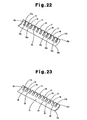
- FIG. 22 is a perspective view of an impeller blade of a multi-blade fan in accordance with a sixth embodiment as seen from a negative pressure surface;
- FIG. 23 is a perspective view of an impeller blade of a multi-blade fan in accordance with a seventh embodiment as seen from a pressure surface;
- FIG. 24 is a perspective view of the impeller blade as seen from the negative pressure surface
- FIG. 25 is a perspective view of an impeller blade of a multi-blade fan in accordance with an eighth embodiment as seen from a negative pressure surface;
- FIG. 26 is a vertical cross-sectional view of a wall mounted type air conditioner provided with a multi-blade fan;
- FIG. 27 is a perspective view showing the entire structure of an impeller
- FIG. 28 is an enlarged perspective view showing a part of the impeller
- FIG. 29 is a perspective view showing a conventional impeller blade
- FIG. 30 is an enlarged front view showing a portion in the vicinity of an outer end portion of the impeller blade
- FIG. 31 is a schematic view showing air flow at a time of using the conventional impeller
- FIG. 32 is a schematic view showing air flow within the impeller
- FIG. 33( a ) is a cross-sectional view taken along line 33 ( a )- 33 ( a ) in FIG. 30 ;
- FIG. 33( b ) is a cross-sectional view taken along line 33 ( b )- 33 ( b ) in FIG. 30 ;
- FIG. 34 is an explanatory view for explaining the wind speed distribution in side plates of an impeller and both side walls of a main body casing.
- An impeller of a multi-blade fan in accordance with the present embodiment is formed as a forward swept structure in the same manner as the conventional structure shown in FIG. 27 . Further, the impeller is provided with a plurality of circular support plates 14 , and a plurality of impeller blades 15 each having a circular arc shaped cross section.
- the circular support plates 14 are arranged in parallel to each other so as to be spaced at a predetermined interval along a rotary shaft 16 .
- Each of the impeller blades 15 is arranged at a predetermined blade angle with respect to the rotary shaft 16 , in an outer periphery of each of the circular support plates 14 .
- a plurality of notches 17 formed as a regular triangle shape are provided in a blade edge 15 a in an outer side of each of the impeller blades 15 so as to be spaced at a predetermined interval along the longitudinal direction of the impeller blade 15 .
- a plurality of smooth portions (unnotched portions) 18 forming a part of the blade edge are provided in the blade edge 15 a in the outer side of each of the impeller blades 15 .
- Each of the smooth portions 18 has a predetermined width, and is provided between adjacent notches 17 .
- a triangular pyramid-shaped projection 19 is provided in the vicinity of the rear portion of each notch 17 in the pressure surface (the concave surface) of the impeller blade, as shown in FIGS. 1 , 2 , 4 and 5 . Accordingly, it is possible to direct the impeller blade outlet in the portion of the notch portion to the circumferential direction, and it is possible to direct the air flow blown out of the fan sufficiently to the circumferential direction. It is thus possible to effectively increase the fan pressure.
- the multi-blade fan 3 in which a plurality of notches 17 are provided in the blade edge 15 a in the outer side of the impeller blade 15 , it is possible to direct the impeller blade outlet in the portion of the notches 17 sufficiently to the circumferential direction in the same manner as the portion having no notch 17 (shown by a broken line) as shown by a solid line in FIG. 6 , by setting the triangular pyramid-shaped projection 19 in the vicinity of the rear portion of each notch 17 in the pressure surface of the impeller blade. Accordingly, it is possible to increase the fan pressure.
- the blade edge 15 a of the impeller blade 15 is not planar, it is possible to suppress the trailing vortex generated at a time of blowing in the vicinity of the trailing edge of the blade, and it is possible to further effectively reduce the noise.
- each projection 19 is set so as to become smaller toward the blade edge 15 a , for smoothening the air flow on the pressure surface of the impeller blade.
- the outer end portion of the impeller blade does not become planar, it is possible to effectively suppress the trailing vortex generated in the vicinity of the trailing edge of the blade at a time of blowing, and it is possible to reduce the noise.
- the triangular notches 17 shown in the first embodiment are replaced by rectangular notches 17 , and a rectangular projection 20 is provided in the vicinity of the rear portion of each notch 17 in the pressure surface of the impeller blade 15 . Accordingly, the impeller blade outlet in the portion of the notches 17 is directed to the circumferential direction. Accordingly, it is possible to direct the air flow blown out of the fan to the circumferential direction, and it is possible to effectively increase the fan pressure.
- the multi-blade fan 3 provided with a plurality of notches 17 in the blade edge 15 a in the outer side of the impeller blade 15 , it is possible to direct the impeller blade outlet in the portion of the notches 17 sufficiently to the circumferential direction in the same manner as the portion (shown by a broken line) having no notch 17 , as shown by a solid line in FIG. 6 , by setting the rectangular projection 20 in the vicinity of the rear portion of each notch 17 in the pressure surface of the impeller blade. Accordingly, it is possible to increase the fan pressure.
- the blade edge 15 a of the impeller blade 15 is not planar, it is possible to suppress the trailing vortex generated at a time of blowing in the vicinity of the trailing edge of the blade, and it is possible to further effectively reduce the noise.
- the same triangular notches 17 as the first embodiment are provided in the blade edge 15 a of the impeller blade 15 , and the triangular pyramid-shaped projections 19 are provided in the vicinity of the rear portion of the notches 17 in the pressure surface of the impeller blade 15 . Accordingly, it is possible to direct the impeller blade outlet in the portion of the notches 17 to the circumferential direction. Therefore, it is possible to direct the air flow blown out of the fan to the circumferential direction, and it is possible to effectively increase the fan pressure. Further, in the present embodiment, the impeller blade 15 has recesses 19 a in a negative pressure surface on an opposite side to the pressure surface.
- Each recess 19 a is formed by removing a portion corresponding to the projection 19 in the negative pressure surface of the impeller blade 15 . Accordingly, recess and projection are provided in the vicinity of each rear portion of the notch 17 , in the impeller blade 15 .
- the projection and the recess in the vicinity of the rear portion of each notch 17 may extend along a circular arc having the same curvature. In this case, it is possible to easily form the projection and the recess, and the cost is reduced. Further, the projection and the recess may extend along a plurality of circular arcs having different curvatures. In this case, the air flows more easily between adjacent blades, and it is possible to further improve the fan pressure.
- each recess 19 a is set in such a manner as to become smaller toward the blade edge 15 a of the impeller blade 15 .
- the same rectangular notches 17 as the second embodiment are provided in the blade edge 15 a in the outer side of the impeller blade 15 , and projections 20 are provided in the vicinity of the rear end of the notches 17 in the pressure surface of the impeller blade 15 . Accordingly, it is possible to direct the impeller blade outlet in the portion of the notches 17 to the circumferential direction. Therefore, it is possible to direct the air flow blown out of the fan to the circumferential direction, and it is possible to effectively increase the fan pressure. Further, in the present embodiment, as shown in FIGS. 14 and 15 , the impeller blade 15 has recesses 20 a in a negative pressure surface in an opposite side to the pressure surface.
- Each recess 20 a is formed by removing a portion corresponding to the projection 20 in the negative pressure surface of the impeller blade 15 . Accordingly, recess and projection are provided in the vicinity of the rear portion of each notch 17 in the impeller blade 15 .
- the width and the depth of notches 17 a in the vicinity of both ends of the impeller blade 15 are set smaller than the width and the depth of each notch 17 provided in the center portion of the impeller blade 15 .
- a multi-blade fan such as a cross flow fan has a plurality of side plates 14 for securely fixing a plurality of impeller blades 15 arranged in the circumferential direction and securing the strength of the impeller 7 .
- the side plates 14 are provided in both ends and a center portion in the longitudinal direction of the impeller 7 . Accordingly, as shown in FIG. 34 , the air flow velocity FV is lowered in the vicinity of each of the side plates 14 due to an influence of the side plate 14 .
- a sufficiently high wind velocity FV 1 is obtained in the portion having no side plate 14 .
- the wind velocity FV 2 is lowered in the vicinity of each side plate 14
- the wind velocity FV 3 is lowered more largely than the wind velocity FV 2 in the vicinity of both ends of the impeller 7 which is adjacent to both side walls 1 a and 1 b of the main body casing 1 .
- the excessive reduction of the fan pressure is caused in the same manner as the case where the larger recesses than the notches 17 for obtaining the noise reducing effect are arranged in the vicinity of both ends of the impeller blade 15 .
- the notches 17 a (refer to FIG. 21 ) in both ends of the impeller blade 15 (in the portion close to each side plate 14 ) are formed smaller than the notches 17 (refer to FIG. 20 ) in the center portion of the impeller blade 15 . Therefore, the noise reducing effect obtained by the notches 17 and 17 a is sufficiently maintained. Further, in comparison with the structure in which the notches 17 having the same size are only provided discontinuously all over the entire impeller blade 15 , it is possible to further increase the fan pressure and it is possible to avoid the reduction of the blowing performance.
- the width and the depth of the notches 17 a in the vicinity of both ends of the impeller blade 15 are set smaller than the notches 17 provided in the center portion of the impeller blade 15 .
- a multi-blade fan such as a cross flow fan has a plurality of side plates 14 for fixing a plurality of impeller blades 15 arranged in the circumferential direction and securing the strength of the impeller 7 .
- the side plates 14 are provided in both ends and the center portion in the longitudinal direction of the impeller 7 . Accordingly, as shown in FIG. 34 , the air flow velocity FV is lowered in the vicinity of each of the side plates 14 due to an influence of the side plate 14 .
- a sufficiently high wind velocity FV 1 can be obtained in the portion having no side plate 14 .
- the wind velocity FV 2 is lowered in the vicinity of each side plate 14
- the wind velocity FV 3 is lowered more largely than the wind velocity FV 2 in the vicinity of both ends of the impeller 7 which is adjacent to both side walls 1 a and 1 b of the main body casing 1 .
- the excessive reduction of the fan pressure is caused in the same manner as the case where the larger recesses than the notches 17 for obtaining the noise reducing effect are arranged in the vicinity of both ends of the impeller blade 15 .
- the notches 17 a in both ends of the impeller blade 15 are formed smaller than the notches 17 provided in the center portion of the impeller blade 15 . Therefore, the noise reducing effect obtained by the notches 17 and 17 a is sufficiently maintained. Further, in comparison with the structure in which the notches 17 having the same size are only provided discontinuously all over the entire impeller blade 15 , it is possible to further increase the fan pressure and it is possible to avoid the reduction of the blowing performance.
- the width and the depth of the notches 17 a in the vicinity of both ends of the impeller blade 15 are set smaller than the width and the depth of the notches 17 provided in the center portion of the impeller blade 15 .
- a multi-blade fan such as a cross flow fan has a plurality of side plates 14 for fixing a plurality of impeller blades 15 arranged in the circumferential direction and securing the strength of the impeller 7 .
- the side plates 14 are provided in both ends and the center portion in the longitudinal direction of the impeller 7 . Accordingly, as shown in FIG. 34 , the air flow velocity FV is lowered in the vicinity of each of the side plates 14 due to an influence of the side plate 14 .
- a sufficiently high wind velocity FV 1 is obtained in the portion having no side plate 14 .
- the wind velocity FV 2 is lowered in the vicinity of each side plate 14 , and the wind velocity FV 3 is lowered more largely than the wind velocity FV 2 in both end portions of the impeller 7 which is adjacent to both side walls 1 a and 1 b of the main body casing 1 .
- the excessive reduction of the fan pressure is caused in the same manner as the case where the larger recesses than the notches 17 for obtaining the noise reducing effect are arranged in the vicinity of both ends of the impeller blade 15 .
- the notches 17 a in both ends of the impeller blade 15 are formed smaller than the notches 17 provided in the center portion of the impeller blade 15 . Therefore, the noise reducing effect obtained by the notches 17 and 17 a is sufficiently maintained. Further, in comparison with the structure in which the notches 17 having the same size are only provided discontinuously all over the entire impeller blade 15 , it is possible to further increase the fan pressure and it is possible to avoid the reduction of the blowing performance.
- the width and the depth of the notches 17 a in the vicinity of both ends of the impeller blade 15 are set smaller than the width and the depth of the notches 17 provided in the center portion of the impeller blade 15 .
- a multi-blade fan such as a cross flow fan or the like has a plurality of side plates 14 for fixing a plurality of impeller blades 15 arranged in the circumferential direction and securing the strength of the impeller 7 .
- the side plates 14 are provided in both ends and the center portion in the longitudinal direction of the impeller 7 . Accordingly, as shown in FIG. 34 , the air flow velocity FV is lowered in the vicinity of each of the side plates 14 due to an influence of the side plate 14 .
- a sufficiently high wind velocity FV 1 can be obtained in the portion having no side plate 14 , however, the wind velocity FV 2 is lowered in the vicinity of each side plate 14 , and the wind velocity FV 3 is lowered more largely than the wind velocity FV 2 in both end portions of the impeller 7 which is adjacent to both side walls 1 a and 1 b of the main body casing 1 .
- the excessive reduction of the fan pressure is caused in the same manner as the case where the larger recesses than the notches 17 for obtaining the noise reducing effect are arranged in the vicinity of both ends of the impeller blade 15 .
- the notches 17 a in both ends of the impeller blade 15 are formed smaller than the notches 17 provided in the center portion of the impeller blade 15 . Therefore, the noise reducing effect obtained by the notches 17 and 17 a is sufficiently maintained. Further, in comparison with the structure in which the notches 17 having the same size are only provided discontinuously all over the entire impeller blade 15 , it is possible to further increase the fan pressure and it is possible to avoid the reduction of the blowing performance.
- the size reduction degree of the notches 17 a formed relatively small may be changed, or the number of the notches 17 a may be increased as appropriate. Accordingly, it is possible to increase the air flow velocity, and the blowing performance is improved as much as possible.
- the impeller 7 has no side plate 14 in the portions except both ends thereof, it is preferable to set one or a plurality of notches 17 a in both ends of the impeller 7 , thereby forming the notches 17 a relatively small.
- the noise reducing effect by the notches 17 and 17 a is maintained. Further, in comparison with the structure in which the notches 17 having the same size are only provided discontinuously, it is possible to further increase the fan pressure.
Landscapes
- Engineering & Computer Science (AREA)
- Mechanical Engineering (AREA)
- General Engineering & Computer Science (AREA)
- Chemical & Material Sciences (AREA)
- Combustion & Propulsion (AREA)
- Structures Of Non-Positive Displacement Pumps (AREA)
- Air-Conditioning Room Units, And Self-Contained Units In General (AREA)
Applications Claiming Priority (5)
| Application Number | Priority Date | Filing Date | Title |
|---|---|---|---|
| JP2006-097078 | 2006-03-31 | ||
| JP2006097078 | 2006-03-31 | ||
| JP2007-062198 | 2007-03-12 | ||
| JP2007062198A JP4973249B2 (ja) | 2006-03-31 | 2007-03-12 | 多翼ファン |
| PCT/JP2007/056148 WO2007114090A1 (ja) | 2006-03-31 | 2007-03-26 | 多翼ファン |
Publications (2)
| Publication Number | Publication Date |
|---|---|
| US20090028719A1 US20090028719A1 (en) | 2009-01-29 |
| US8029242B2 true US8029242B2 (en) | 2011-10-04 |
Family
ID=38563359
Family Applications (1)
| Application Number | Title | Priority Date | Filing Date |
|---|---|---|---|
| US12/224,724 Active 2028-11-25 US8029242B2 (en) | 2006-03-31 | 2007-03-26 | Multi-blade fan |
Country Status (7)
| Country | Link |
|---|---|
| US (1) | US8029242B2 (de) |
| EP (1) | EP2003340B1 (de) |
| JP (1) | JP4973249B2 (de) |
| KR (1) | KR100985958B1 (de) |
| CN (1) | CN101405506B (de) |
| AU (1) | AU2007233449B2 (de) |
| WO (1) | WO2007114090A1 (de) |
Cited By (7)
| Publication number | Priority date | Publication date | Assignee | Title |
|---|---|---|---|---|
| US20110006165A1 (en) * | 2009-07-10 | 2011-01-13 | Peter Ireland | Application of conformal sub boundary layer vortex generators to a foil or aero/ hydrodynamic surface |
| US20110033306A1 (en) * | 2008-05-09 | 2011-02-10 | Hironobu Teraoka | Cross-flow fan and air conditioner equipped with same |
| US20140301860A1 (en) * | 2013-04-09 | 2014-10-09 | MTU Aero Engines AG | Airfoil having a profiled trailing edge for a fluid flow machine, blade, and integrally blade rotor |
| US20150056910A1 (en) * | 2012-04-06 | 2015-02-26 | Mitsubishi Electric Corporation | Indoor unit for air-conditioning apparatus |
| US20150292508A1 (en) * | 2012-11-22 | 2015-10-15 | Mitsubishi Electric Corporation | Air conditioner |
| US20170022820A1 (en) * | 2015-07-20 | 2017-01-26 | Rolls-Royce Plc | Aerofoil |
| US20240376898A1 (en) * | 2021-11-16 | 2024-11-14 | Mitsubishi Electric Corporation | Cross flow fan |
Families Citing this family (36)
| Publication number | Priority date | Publication date | Assignee | Title |
|---|---|---|---|---|
| GB0606890D0 (en) * | 2006-04-05 | 2006-05-17 | Imp College Innovations Ltd | Fluid flow modification apparatus |
| JP4840343B2 (ja) * | 2007-11-30 | 2011-12-21 | 三菱電機株式会社 | 貫流ファン及び空気調和機 |
| JP4400686B2 (ja) | 2008-01-07 | 2010-01-20 | ダイキン工業株式会社 | プロペラファン |
| JP4433093B2 (ja) * | 2008-05-09 | 2010-03-17 | ダイキン工業株式会社 | クロスフローファン及びこれを備えた空気調和機 |
| JP4957774B2 (ja) * | 2008-05-09 | 2012-06-20 | ダイキン工業株式会社 | クロスフローファン及びこれを備えた空気調和機 |
| KR101281748B1 (ko) | 2008-10-23 | 2013-07-04 | 엘지디스플레이 주식회사 | 상부 발광방식 유기전계발광소자 |
| CN102341601B (zh) * | 2009-03-10 | 2014-07-23 | 大金工业株式会社 | 横流风扇和具有该横流风扇的空调机 |
| US20100322774A1 (en) * | 2009-06-17 | 2010-12-23 | Morrison Jay A | Airfoil Having an Improved Trailing Edge |
| JP4761323B2 (ja) | 2009-09-09 | 2011-08-31 | シャープ株式会社 | 遠心ファン、成型用金型および流体送り装置 |
| JP4761324B2 (ja) * | 2009-09-09 | 2011-08-31 | シャープ株式会社 | 貫流ファン、成型用金型および流体送り装置 |
| UA107094C2 (xx) | 2009-11-03 | 2014-11-25 | Відцентровий стельовий вентилятор | |
| WO2011097024A1 (en) * | 2010-02-02 | 2011-08-11 | Garden Energy, Inc. | Wind power generation system |
| JP5143173B2 (ja) * | 2010-03-29 | 2013-02-13 | 三菱電機株式会社 | ターボファン及びこれを装備した空気調和機の室内機 |
| GB201016455D0 (en) * | 2010-09-30 | 2010-11-17 | Imp Innovations Ltd | Fluid flow modification |
| JP2012112640A (ja) * | 2010-11-05 | 2012-06-14 | Daikin Industries Ltd | 空気調和機 |
| KR101826348B1 (ko) * | 2011-01-06 | 2018-02-06 | 엘지전자 주식회사 | 횡류팬 및 이를 구비한 공기 조화기 |
| JP5203478B2 (ja) * | 2011-03-02 | 2013-06-05 | シャープ株式会社 | 貫流ファン、成型用金型および流体送り装置 |
| JP5264960B2 (ja) * | 2011-05-20 | 2013-08-14 | 三菱電機株式会社 | 貫流ファン及び空気調和機 |
| KR101826359B1 (ko) | 2011-11-22 | 2018-02-06 | 엘지전자 주식회사 | 횡류팬 및 공기 조화기 |
| EP2597316B1 (de) * | 2011-11-22 | 2021-01-13 | Lg Electronics Inc. | Querstromventilator und klimaanlage |
| KR101883502B1 (ko) * | 2011-11-22 | 2018-07-30 | 엘지전자 주식회사 | 횡류팬 및 공기 조화기 |
| WO2014038467A1 (ja) * | 2012-09-04 | 2014-03-13 | ダイキン工業株式会社 | クロスフローファン |
| KR101920085B1 (ko) * | 2012-09-12 | 2018-11-19 | 엘지전자 주식회사 | 팬 |
| JP5575288B2 (ja) * | 2013-02-22 | 2014-08-20 | 三菱電機株式会社 | 貫流ファン及び空気調和機 |
| CN104251231A (zh) * | 2013-06-28 | 2014-12-31 | 苏州宝时得电动工具有限公司 | 离心式叶轮及包括该离心式叶轮的吹吸装置 |
| DE112015001218T5 (de) * | 2014-03-13 | 2017-02-02 | Magna Electronics, Inc. | Fahrzeugkühllüfter mit aerodynamischen Statorstreben |
| CN107076164B (zh) * | 2014-10-30 | 2019-05-28 | 三菱电机株式会社 | 涡轮风扇和空气调节装置用室内机 |
| GB201718069D0 (en) | 2017-11-01 | 2017-12-13 | Rolls Royce Plc | Aerofoil |
| CN108327892B (zh) * | 2017-12-30 | 2024-04-09 | 镇江同舟螺旋桨有限公司 | 稍部折翼型螺旋桨叶片稍部造型方法 |
| CN112880027B (zh) * | 2019-11-30 | 2025-06-03 | 广东美的制冷设备有限公司 | 空调室内机和空调器 |
| CN114867944B (zh) * | 2019-12-09 | 2024-01-26 | Lg电子株式会社 | 送风机 |
| JP7707154B2 (ja) * | 2020-04-22 | 2025-07-14 | 株式会社ニコン | ブレード、加工システム及び加工方法 |
| CN112049817B (zh) * | 2020-08-13 | 2022-04-12 | 东南大学 | 一种基于仿生学的贯流风机叶片 |
| CN112983862B (zh) * | 2021-03-04 | 2024-07-09 | 青岛海尔空调电子有限公司 | 离心风扇 |
| CN116265761B (zh) * | 2021-12-16 | 2026-01-23 | 宁波奥克斯电气有限公司 | 斜扭贯流风叶和空调器 |
| DE102024202469A1 (de) | 2024-03-15 | 2025-09-18 | Ziehl-Abegg Se | Flügel für das Laufrad eines Ventilators, Laufrad sowie Axialventilator, Diagonalventilator oder Radialventilator |
Citations (12)
| Publication number | Priority date | Publication date | Assignee | Title |
|---|---|---|---|---|
| JPS53144508A (en) | 1977-05-20 | 1978-12-15 | Neos Kk | Process for preparing perfluoroolefin oligomer |
| JPS63124899A (ja) | 1986-11-14 | 1988-05-28 | Hitachi Ltd | クロスフアン用ブレ−ド |
| US4813633A (en) * | 1986-12-29 | 1989-03-21 | United Technologies Corporation | Airfoil trailing edge |
| JPH03249400A (ja) | 1990-02-28 | 1991-11-07 | Matsushita Electric Ind Co Ltd | 多翼送風機の羽根車 |
| US5533865A (en) * | 1993-11-04 | 1996-07-09 | Stork Product Engineering B.V. | Wind turbine |
| JPH11101198A (ja) | 1997-09-30 | 1999-04-13 | Daikin Ind Ltd | 遠心送風機及びその製造方法並びに該遠心送風機を備えた空気調和機 |
| JPH11141494A (ja) | 1997-11-10 | 1999-05-25 | Daikin Ind Ltd | 多翼送風機の羽根車構造 |
| US6830436B2 (en) * | 2002-02-22 | 2004-12-14 | Mitsubishi Heavy Industries, Ltd. | Wind turbine provided with nacelle |
| JP2005120877A (ja) | 2003-10-15 | 2005-05-12 | Haruo Yoshida | 横断流送風機用羽根車および横断流送風機 |
| JP2005351141A (ja) | 2004-06-09 | 2005-12-22 | Calsonic Kansei Corp | 送風機 |
| JP2006125390A (ja) | 2004-09-30 | 2006-05-18 | Daikin Ind Ltd | 送風機の羽根車およびそれを用いた空気調和機 |
| US20060269419A1 (en) * | 2005-05-27 | 2006-11-30 | United Technologies Corporation | Turbine blade trailing edge construction |
Family Cites Families (7)
| Publication number | Priority date | Publication date | Assignee | Title |
|---|---|---|---|---|
| JPS53144508U (de) * | 1977-04-20 | 1978-11-14 | ||
| JP3111963B2 (ja) * | 1998-01-27 | 2000-11-27 | ダイキン工業株式会社 | 送風機用羽根車の羽根および送風機用羽根車 |
| CN2381819Y (zh) * | 1999-07-20 | 2000-06-07 | 吴东和 | 多翼风扇的改良结构 |
| JP2002257078A (ja) * | 2001-02-26 | 2002-09-11 | Matsushita Electric Ind Co Ltd | 多翼形羽根車とその製造方法 |
| CN1188603C (zh) * | 2002-08-19 | 2005-02-09 | 乐金电子(天津)电器有限公司 | 空调机用送风机 |
| EP1574716B1 (de) * | 2004-03-05 | 2008-08-13 | Matsushita Electric Industrial Co., Ltd. | Lüfter |
| JP2005269765A (ja) | 2004-03-18 | 2005-09-29 | Denso Trim Kk | 磁石式発電機 |
-
2007
- 2007-03-12 JP JP2007062198A patent/JP4973249B2/ja not_active Expired - Fee Related
- 2007-03-26 US US12/224,724 patent/US8029242B2/en active Active
- 2007-03-26 CN CN2007800094721A patent/CN101405506B/zh not_active Expired - Fee Related
- 2007-03-26 AU AU2007233449A patent/AU2007233449B2/en not_active Ceased
- 2007-03-26 WO PCT/JP2007/056148 patent/WO2007114090A1/ja not_active Ceased
- 2007-03-26 EP EP07739587.9A patent/EP2003340B1/de not_active Not-in-force
- 2007-03-26 KR KR1020087023962A patent/KR100985958B1/ko active Active
Patent Citations (14)
| Publication number | Priority date | Publication date | Assignee | Title |
|---|---|---|---|---|
| JPS53144508A (en) | 1977-05-20 | 1978-12-15 | Neos Kk | Process for preparing perfluoroolefin oligomer |
| JPS63124899A (ja) | 1986-11-14 | 1988-05-28 | Hitachi Ltd | クロスフアン用ブレ−ド |
| US4813633A (en) * | 1986-12-29 | 1989-03-21 | United Technologies Corporation | Airfoil trailing edge |
| JPH03249400A (ja) | 1990-02-28 | 1991-11-07 | Matsushita Electric Ind Co Ltd | 多翼送風機の羽根車 |
| US5533865A (en) * | 1993-11-04 | 1996-07-09 | Stork Product Engineering B.V. | Wind turbine |
| EP0942175A1 (de) | 1997-09-30 | 1999-09-15 | Daikin Industries, Limited | Zentrifugalgebläse, herstellungsverfahren dafür sowie klimaanlage mit einem solchem gebläse |
| JPH11101198A (ja) | 1997-09-30 | 1999-04-13 | Daikin Ind Ltd | 遠心送風機及びその製造方法並びに該遠心送風機を備えた空気調和機 |
| JPH11141494A (ja) | 1997-11-10 | 1999-05-25 | Daikin Ind Ltd | 多翼送風機の羽根車構造 |
| US6830436B2 (en) * | 2002-02-22 | 2004-12-14 | Mitsubishi Heavy Industries, Ltd. | Wind turbine provided with nacelle |
| JP2005120877A (ja) | 2003-10-15 | 2005-05-12 | Haruo Yoshida | 横断流送風機用羽根車および横断流送風機 |
| JP2005351141A (ja) | 2004-06-09 | 2005-12-22 | Calsonic Kansei Corp | 送風機 |
| JP2006125390A (ja) | 2004-09-30 | 2006-05-18 | Daikin Ind Ltd | 送風機の羽根車およびそれを用いた空気調和機 |
| US7815419B2 (en) * | 2004-09-30 | 2010-10-19 | Daikin Industries, Ltd. | Impeller for blower and air conditioner having the same |
| US20060269419A1 (en) * | 2005-05-27 | 2006-11-30 | United Technologies Corporation | Turbine blade trailing edge construction |
Cited By (11)
| Publication number | Priority date | Publication date | Assignee | Title |
|---|---|---|---|---|
| US20110033306A1 (en) * | 2008-05-09 | 2011-02-10 | Hironobu Teraoka | Cross-flow fan and air conditioner equipped with same |
| US20110006165A1 (en) * | 2009-07-10 | 2011-01-13 | Peter Ireland | Application of conformal sub boundary layer vortex generators to a foil or aero/ hydrodynamic surface |
| US20150056910A1 (en) * | 2012-04-06 | 2015-02-26 | Mitsubishi Electric Corporation | Indoor unit for air-conditioning apparatus |
| US10436496B2 (en) * | 2012-04-06 | 2019-10-08 | Mitsubishi Electric Corporation | Indoor unit for air-conditioning apparatus |
| US20150292508A1 (en) * | 2012-11-22 | 2015-10-15 | Mitsubishi Electric Corporation | Air conditioner |
| US9995303B2 (en) * | 2012-11-22 | 2018-06-12 | Mitsubishi Electric Corporation | Air conditioner |
| US20140301860A1 (en) * | 2013-04-09 | 2014-10-09 | MTU Aero Engines AG | Airfoil having a profiled trailing edge for a fluid flow machine, blade, and integrally blade rotor |
| US9657576B2 (en) * | 2013-04-09 | 2017-05-23 | MTU Aero Engines AG | Airfoil having a profiled trailing edge for a fluid flow machine, blade, and integrally blade rotor |
| US20170022820A1 (en) * | 2015-07-20 | 2017-01-26 | Rolls-Royce Plc | Aerofoil |
| US10301942B2 (en) * | 2015-07-20 | 2019-05-28 | Rolls-Royce Plc | Aerofoil |
| US20240376898A1 (en) * | 2021-11-16 | 2024-11-14 | Mitsubishi Electric Corporation | Cross flow fan |
Also Published As
| Publication number | Publication date |
|---|---|
| AU2007233449A1 (en) | 2007-10-11 |
| EP2003340B1 (de) | 2017-08-30 |
| WO2007114090A1 (ja) | 2007-10-11 |
| JP4973249B2 (ja) | 2012-07-11 |
| JP2007292053A (ja) | 2007-11-08 |
| CN101405506B (zh) | 2010-09-01 |
| AU2007233449B2 (en) | 2010-04-29 |
| EP2003340A2 (de) | 2008-12-17 |
| US20090028719A1 (en) | 2009-01-29 |
| EP2003340A4 (de) | 2015-12-02 |
| KR20080104169A (ko) | 2008-12-01 |
| CN101405506A (zh) | 2009-04-08 |
| KR100985958B1 (ko) | 2010-10-06 |
| EP2003340A9 (de) | 2009-04-22 |
Similar Documents
| Publication | Publication Date | Title |
|---|---|---|
| US8029242B2 (en) | Multi-blade fan | |
| US7815419B2 (en) | Impeller for blower and air conditioner having the same | |
| US8834121B2 (en) | Turbo fan and air conditioning apparatus | |
| US8596958B2 (en) | Cross-flow fan and air conditioner equipped with same | |
| EP2902639B1 (de) | Propellerlüfter und klimaanlage damit | |
| CN111577655A (zh) | 叶片及使用其的轴流叶轮 | |
| JP2003232295A (ja) | 遠心ファンおよびその遠心ファンを備えた加熱調理器 | |
| JP2008261311A (ja) | 多翼ファンの羽根車 | |
| CN114370428A (zh) | 风机叶片及离心风机 | |
| KR101649379B1 (ko) | 횡류팬 및 이를 구비한 공기 조화기 | |
| EP2597315B1 (de) | Querstromventilator und Klimaanlage | |
| JP5596510B2 (ja) | 空気調和機の室内ユニット | |
| JP4918650B2 (ja) | 多翼ファン | |
| EP2280176B1 (de) | Querstromlüfter und klimaanlage damit | |
| JP2013096307A (ja) | 送風機、送風機ユニット及び冷却塔 | |
| KR101826348B1 (ko) | 횡류팬 및 이를 구비한 공기 조화기 | |
| CN121701504A (zh) | 一种多翼离心风机 | |
| KR100829642B1 (ko) | 축류팬 및 이를 포함하는 공기조화기의 실외기 | |
| CN117419069A (zh) | 叶轮、风机和油烟机 |
Legal Events
| Date | Code | Title | Description |
|---|---|---|---|
| AS | Assignment |
Owner name: DAIKIN INDUSTRIES, LTD., JAPAN Free format text: ASSIGNMENT OF ASSIGNORS INTEREST;ASSIGNORS:TERAOKA, HIRONOBU;KOMATSU, AKIRA;REEL/FRAME:021514/0588 Effective date: 20070403 |
|
| STCF | Information on status: patent grant |
Free format text: PATENTED CASE |
|
| FEPP | Fee payment procedure |
Free format text: PAYOR NUMBER ASSIGNED (ORIGINAL EVENT CODE: ASPN); ENTITY STATUS OF PATENT OWNER: LARGE ENTITY |
|
| FPAY | Fee payment |
Year of fee payment: 4 |
|
| MAFP | Maintenance fee payment |
Free format text: PAYMENT OF MAINTENANCE FEE, 8TH YEAR, LARGE ENTITY (ORIGINAL EVENT CODE: M1552); ENTITY STATUS OF PATENT OWNER: LARGE ENTITY Year of fee payment: 8 |
|
| MAFP | Maintenance fee payment |
Free format text: PAYMENT OF MAINTENANCE FEE, 12TH YEAR, LARGE ENTITY (ORIGINAL EVENT CODE: M1553); ENTITY STATUS OF PATENT OWNER: LARGE ENTITY Year of fee payment: 12 |