US8046027B2 - Apparatus for using a wireless communication base station in common - Google Patents
Apparatus for using a wireless communication base station in common Download PDFInfo
- Publication number
- US8046027B2 US8046027B2 US11/824,250 US82425007A US8046027B2 US 8046027 B2 US8046027 B2 US 8046027B2 US 82425007 A US82425007 A US 82425007A US 8046027 B2 US8046027 B2 US 8046027B2
- Authority
- US
- United States
- Prior art keywords
- port
- signal
- distributor
- magic
- ports
- Prior art date
- Legal status (The legal status is an assumption and is not a legal conclusion. Google has not performed a legal analysis and makes no representation as to the accuracy of the status listed.)
- Active, expires
Links
Images




Classifications
-
- H—ELECTRICITY
- H04—ELECTRIC COMMUNICATION TECHNIQUE
- H04W—WIRELESS COMMUNICATION NETWORKS
- H04W88/00—Devices specially adapted for wireless communication networks, e.g. terminals, base stations or access point devices
- H04W88/08—Access point devices
-
- H—ELECTRICITY
- H04—ELECTRIC COMMUNICATION TECHNIQUE
- H04B—TRANSMISSION
- H04B1/00—Details of transmission systems, not covered by a single one of groups H04B3/00 - H04B13/00; Details of transmission systems not characterised by the medium used for transmission
- H04B1/38—Transceivers, i.e. devices in which transmitter and receiver form a structural unit and in which at least one part is used for functions of transmitting and receiving
- H04B1/40—Circuits
- H04B1/50—Circuits using different frequencies for the two directions of communication
- H04B1/52—Hybrid arrangements, i.e. arrangements for transition from single-path two-direction transmission to single-direction transmission on each of two paths or vice versa
Definitions
- the present invention relates generally to a wireless communication system, and in particular, to a wireless communication base station sharing apparatus for sharing an antenna and a feeder cable in deploying wireless communication systems that provide services in different frequency bands.
- a plurality of service providers provide services through independent base stations (BSs) 10 and 12 in cellular, CDMA, PCS and GSM mobile communication systems and other wireless communication systems.
- BSs independent base stations
- the resulting redundant investment regarding installation of individual BSs and unnecessary existence of too many BSs in an adjacent area lead to signal quality degradation due to mutual interference between the BSs.
- One of the techniques is to share a BS antenna and a feeder cable by use of a new quadroplexer 132 covering the frequency bands of an existing BS system, for example, a system 10 (system A) and a sub-BS system, for example, a system 12 (system B), as illustrated in FIG. 1C .
- a new quadroplexer 132 covering the frequency bands of an existing BS system, for example, a system 10 (system A) and a sub-BS system, for example, a system 12 (system B), as illustrated in FIG. 1C .
- This technique requires fabrication of such a quadroplexer as allows two systems to share an antenna and a feeder cable. Moreover, in case of different frequency bands assigned to a service provider in different areas, many quadroplexers must be fabricated. If the frequency band of a subsystem is changed while the subsystem is operated, sharing an antenna and a feeder cable with a main system, a new quadroplexer is needed. If a plurality of subsystems are added, a plurality of new quadroplexers are to be fabricated.
- an object of the present invention is to provide a wireless communication BS sharing apparatus for allowing an existing main BS system and an added sub-BS system to easily share a BS antenna and a feeder cable irrespective of the frequency band of the sub-BS system in deploying the sub-BS system in addition to the existing main BS system.
- Another object of the present invention is to provide a wireless communication BS sharing apparatus for allowing an existing main BS system and an added sub-BS system to easily share a BS antenna and a feeder cable without using additional equipment even though the frequency bands of the main BS system and the sub-BS system are changed in deploying the sub-BS system in addition to the existing main BS system.
- a further object of the present invention is to provide a wireless communication BS sharing apparatus for, despite a plurality of added sub-BS systems, allowing a main BS system and the sub-BS systems to easily share an antenna and a feeder cable.
- a wireless communication base station sharing apparatus for sharing one antenna between a main system and a subsystem.
- a first signal combiner/distributor is connected to a transmission/reception signal line of a main system duplexer through a first port, distributes a signal received through the first port to second and third ports, combines the signals received through the second and third ports according to the phases of the signals, and provides the combined signal through the first port or a fourth port.
- a second signal combiner/distributor is connected to a transmission/reception signal line of a subsystem duplexer through a fifth port and the antenna through an eighth port, distributes a signal received through the fifth port to sixth and seventh ports, combines the signals received through the sixth and seventh ports according to the phases of the signals, and provides the combined signal through the fifth or eighth port.
- a first filter is provided in a signal path between the second port of the first signal combiner/distributor and the sixth port of the second signal combiner/distributor.
- a second filter is provided in a signal path between the third port of the first signal combiner/distributor and the seventh port of the second signal combiner/distributor.
- FIGS. 1A , 1 B and 1 C are block diagrams illustrating a conventional antenna sharing method
- FIG. 2 is a block diagram of a wireless communication BS sharing apparatus according to an embodiment of the present invention.
- FIG. 3 is a view illustrating the operation of a hybrid coupler illustrated in FIG. 2 ;
- FIG. 4 is a block diagram of a wireless communication BS sharing apparatus according to another embodiment of the present invention.
- FIG. 5 is a view illustrating the operation of a magic T illustrated in FIG. 4 ;
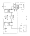
- FIG. 6 is a block diagram of a wireless communication BS sharing apparatus according to a third embodiment of the present invention.
- FIG. 7 is a block diagram of the wireless communication BS sharing apparatus illustrated in FIG. 6 to which a circulator is added;
- FIG. 8 is a block diagram of a wireless communication BS sharing apparatus according to a fourth embodiment of the present invention.
- FIG. 9 is a block diagram of the wireless communication BS sharing apparatus illustrated in FIG. 8 to which a circulator is added;
- FIG. 10 is a block diagram of a wireless communication BS sharing apparatus according to a fifth embodiment of the present invention.
- FIG. 11 is a block diagram of the wireless communication BS sharing apparatus illustrated in FIG. 10 to which a circulator is added.
- FIG. 2 is a block diagram of a wireless communication BS sharing apparatus according to an embodiment of the present invention.
- a wireless communication BS sharing apparatus 20 is so configured as to share an antenna between a main system 22 with a third duplexer 222 and a subsystem 24 with a fourth duplexer 242 .
- This BS sharing apparatus 20 includes the main system with the third duplexer, the subsystem with the fourth duplexer, a first hybrid coupler 202 for distributing a transmission signal received from the main system 22 through a first port and outputting the distributed transmission signals with different phases, a first duplexer 206 connected to a second port of the first hybrid coupler 202 , for filtering transmission and reception signals Rx 1 and Rx 1 of the main system 22 , a second duplexer 208 connected to a third port of the first hybrid coupler 202 , for filtering the transmission and reception signals Tx 1 and Rx 1 of the main system 22 , and a second hybrid coupler 204 with a fifth port connected to the subsystem, for receiving signals from the first and second duplexers 206 and 208 through sixth and seventh ports and combining the signals.
- the antenna is connected to an eighth port of the second hybrid coupler 204 .
- the first and second duplexers 206 and 208 include filters for passing only the transmission and reception frequency bands of the main system 22 . If the main system 22 is exchanged with the subsystem 24 in position, the first and second duplexers 206 and 208 may include filters for passing only the transmission and reception frequency bands of the subsystem 24 .
- the third and fourth duplexers 222 and 242 are full-band duplexers.
- the hybrid couplers characteristically function to partially extract specific signal power and to distribute one signal power into two or more particular signal powers. The latter function will be described in the present invention.
- a signal received through the first port is output through the second and third ports, its power being divided into two halves.
- the signal is not output through the fourth port.
- signals with a 90-degree phase difference are received through the second and third ports, they are combined and output.
- a signal received through the second port has a phase of 90 degrees and a signal received through the third port has a phase of 180 degrees, the two signals are combined and output through the first port, not through the fourth port.
- the two signals are combined and output through the fourth port, not through the first port.
- Such parts with the signal power distributing/combining function are a hybrid ring, a branch-line directional coupler, a 3-dB directional coupler, and a magic T.
- the first hybrid couple 202 receives through the first port the transmission signal TX 1 from the main system 22 which has passed the third duplexer 222 and distributes the received signal to the second and third ports, its phase being rotated by 90 degrees and 180 degrees, respectively for the second and third ports.
- the distributed signals have a phase difference of 90 degrees.
- the signals from the second and third ports pass through the first and second duplexers 206 and 208 that pass only the transmission signal Tx 1 of the main system 22 and are input to the sixth and seventh ports.
- the second hybrid coupler combines the signals received through the sixth and seventh ports and outputs the combined signal through the eighth port. This signal from the eighth port is radiated through the antenna.
- the second hybrid coupler 204 distributes a signal received from the antenna through the eighth port to the sixth and seventh ports, the phase of the signal being rotated by 90 degrees and 180 degrees for the sixth and seventh ports, respectively.
- the first hybrid coupler 202 receives through the second and third ports the signals from the sixth and seventh ports which have passed through the first and second duplexers 206 and 208 , combines the signals, and outputs the combined signal through the first port.
- the signal from the first port is received in the main system 22 through the third duplexer 222 .
- a transmission signal TX 2 from the subsystem 24 passes through the fourth duplexer 242 and is received at the second hybrid coupler 204 through the fifth port.
- the received signal is distributed to the sixth and seventh ports, its phase being rotated by 90 degrees and 180 degrees, respectively for the sixth and seventh ports.
- the distributed signals have a phase difference of 90 degrees.
- the signals from the sixth and seventh ports are fully reflected from the first and second duplexers 206 and 208 and fed back to the sixth and seventh ports.
- the feedback signals are combined and output through the eighth port. This signal from the eighth port is radiated through the antenna.
- the second hybrid coupler 204 distributes a signal received from the antenna through the eighth port to the sixth and seventh ports, the phase of the signal being rotated by 180 degrees and 900 degrees for the sixth and seventh ports, respectively.
- the signals from the sixth and seventh ports are fully reflected from the first and second duplexers 206 and 208 and fed back to the sixth and seventh ports.
- the feedback signals are combined and output through the fifth port. This signal from the fifth port is transferred to a receiver of the subsystem 24 through the fourth duplexer 242 .
- FIG. 4 is a block diagram of a wireless communication BS sharing apparatus according to another embodiment of the present invention.
- a wireless communication BS sharing apparatus 40 includes the main system with the third duplexer, the subsystem with the fourth duplexer, a first magic T 402 for distributing a transmission signal received from the third duplexer 222 of the main system 22 through a first port and outputting the distributed transmission signals with different phases, a first phase rotator 412 for receiving a signal from a second port of the first magic T 402 and rotating the phase of the received signal, a first duplexer 406 for filtering the signal received from the first phase rotator 412 , a second phase rotator 414 for rotating the signal received from the first duplexer 406 , a second duplexer 408 for filtering a signal received from a third port of the first magic T 402 , and a second magic T 404 having a fifth port connected to the fourth duplexer 242 of the subsystem 24 , for receiving the signals from
- the first and second duplexers 406 and 408 are so configured as to pass only the transmission and reception frequency bands of the main system 22 . If the main system 22 is exchanged with the subsystem 24 in position, the first and second duplexers 406 and 408 may include filters for passing only the transmission and reception frequency bands of the subsystem 24 .
- the third and fourth duplexers 222 and 242 are full-band duplexers.
- a signal received through the first port is distributed to the second and third ports with a phase difference of 180 degrees.
- a signal received through the fourth port is distributed to the second and third ports, with the same phase.
- signals with a phase difference of 180 degrees in the same frequency are received through the second and third ports, they are combined and output through the first port. If the same-phase signals are received through the second and third ports, they are combined and output through the fourth port.
- the transmission signal TX 1 from the main system 22 passes through the third duplexer 222 and is input to the first port of the first magic T 402 .
- the first magic T 402 distributes the received signal to the second and third ports, with a phase difference of 180 degrees.
- the signal from the third port passes through the second duplexer 408 and is input to the seventh port of the second magic T 404 .
- the phase of the signal from the second port is rotated by 90 degrees in the first phase rotator 412 .
- the signal from the first phase rotator 412 is phase-rotated by 90 degrees in the second phase rotator 414 and then output to the sixth port of the second magic T 404 .
- the signals received in the second magic T 404 through the sixth and seventh ports have the same phase.
- the second magic T 404 combines these signals and outputs the combined signal through the eighth port.
- the signal from the eighth port is radiated through the antenna.
- the second magic T 404 receives a signal from the antenna through the eighth port and distributes the signal to the sixth and seventh ports, with the same phase.
- the signal from the seventh port is provided to the third port of the first magic T 402 through the second duplexer 408 .
- the signal from the sixth port of the second magic T 404 is phase-rotated by 90 degrees in the second phase rotator 414 , passes through the first duplexer 406 , phase-rotated again by 90 degrees in the first phase rotator 412 , and then provided to the second port of the first magic T 402 .
- the first magic T 402 receives the signals with a phase difference of 180 degrees through the second and third ports, combines them, and outputs the combined signal through the first port.
- the signal from the first port is provided to a receiver of the main system 22 through the third duplexer 222 .
- the transmission signal TX 2 from the subsystem 24 passes through the fourth duplexer 242 and is provided to the fifth port of the second magic T 404 .
- the second magic T 404 distributes the received signal to the sixth and seventh ports, with a phase difference of 180 degrees.
- the signal from the seventh port is fully reflected from the second duplexer 208 and fed back to the seventh port.
- the signal from the sixth port is phase-rotated by 90 degrees in the second phase rotator 414 , it is also fully reflected form the first duplexer 406 , again phase-rotated by 90 degrees in the second phase rotator 414 , and fed back to the sixth port.
- the second magic T 404 receives the signals with the same phase through the sixth and seventh ports, combines them, and outputs the combined signal through the eighth port. This signal from the eighth port is radiated through the antenna.
- the second magic T 404 receives a signal from the antenna through the eighth port and distributes the received signal to the sixth and seventh ports, with the same phase.
- the signal from the seventh port is fully reflected from the second duplexer 208 and fed back to the seventh port.
- the signal from the sixth port is phase-rotated by 90 degrees in the second phase rotator 414 , it is also fully reflected form the first duplexer 406 , again phase-rotated by 90 degrees in the second phase rotator 414 , and fed back to the sixth port.
- the second magic T 404 receives the signals with a phase difference of 180 degrees through the sixth and seventh ports, combines them, and outputs the combined signal through the fifth port.
- This signal from the fifth port is provided to the receiver of the subsystem 24 through the fourth duplexer 242 .
- the load resistor TERM is provided at the fourth port, for isolation.
- first and second duplexers 206 , 208 , 406 and 408 are implemented by variable-frequency filters, instead of fixed-frequency filters.
- the present applicant has already filed applications for a variable-frequency filter for use in variable frequency bands, as Korean Patent Application No. 2003-58556, No. 2004-36623, and No. 2004-46103.
- an active action can be taken against a change in the transmission frequency TX 1 or TX 2 of the main system 22 or the subsystem 24 . That is, even though another system is added to an existing system or the frequency band of the existing system is changed, this situation can be dealt with without using additional equipment.
- FIG. 6 is a block diagram of a wireless communication BS sharing apparatus according to a third embodiment of the present invention.
- a wireless communication BS sharing apparatus 60 is so configured as to share an antenna between the main system 22 with the third duplexer 222 and a subsystem 26 .
- This BS sharing apparatus 60 includes the main system with the third duplexer, the subsystem, a first hybrid coupler 602 for distributing a transmission signal received from the third duplexer 222 through a first port and a signal received from the antenna through a fourth port and outputting the distributed signals with different phases, a first band-pass filter 606 for filtering a signal received from a second port of the first hybrid coupler 602 , a second band-pass filter 608 for filtering a signal received from a third port of the first hybrid coupler 602 , a second hybrid coupler 604 for receiving signals from the first and second band-pass filters 606 and 608 through sixth and seventh ports and combining the signals, a fourth duplexer 622 connected to a fifth port of the second hybrid coupler 604 and the subsystem 26 , a distributor 624 connected between a receiver Rx of the fourth duplexer 622 and the subsystem 26 , for distributing a signal received from the receiver Rx of the fourth duplexer 622 , and a reception filter
- the antenna is connected to an eighth port of the second hybrid coupler 604 .
- the receivers Rx of the third and fourth duplexers 222 and 622 , and the reception filter 626 can be implemented by filters that pass both reception frequencies of the main system 22 and the subsystem 26 , or full-band reception filters for passing the reception frequency band of the main system 22 and the subsystem 26 in a particular band (e.g. PCS band).
- the first and second band-pass filters 606 and 608 are so configured as to pass only the transmission frequency band of the main system 22 .
- the first and second duplexers 606 and 608 may include filters for passing only the transmission frequency band of the subsystem 26 .
- the fourth duplexer 622 may not be provided if it already exists in the subsystem 26 . Needless to say, the subsystem 26 must have the distributor 624 in this case.
- the first hybrid couple 602 receives through the first port the transmission signal TX 1 from the main system 22 which has passed the third duplexer 222 and distributes the received signal to the second and third ports, its phase being rotated by 90 degrees and 180 degrees, respectively for the second and third ports.
- the distributed signals have a phase difference of 90 degrees.
- the signals from the second and third ports pass through the first and second band-pass filters 606 and 608 that pass only the transmission signal Tx 1 of the main system 22 and are provided to the sixth and seventh ports of the second hybrid coupler 604 .
- the second hybrid coupler 604 combines the received signals and outputs the combined signal through the eighth port. This signal from the eighth port is radiated through the antenna.
- the second hybrid coupler 604 distributes a signal received from the antenna through the eighth port to the sixth and seventh ports, the phase of the signal being rotated by 180 degrees and 90 degrees for the sixth and seventh ports, respectively.
- the signals from the sixth and seventh ports are fully reflected from the first and second band-pass filters 606 and 608 and fed back to the sixth and seventh ports.
- the feedback signals are combined and output through the fifth port.
- the distributor 624 receives the signal from the fifth port through the fourth duplexer 622 and distributes the received signal.
- One of the distributed signals is provided to the subsystem 26 and the other is provided to the fourth port of the first hybrid coupler 602 through the reception filter 626 .
- the first hybrid coupler 602 distributes the received signal to the second and third ports with a phase difference of 90 degrees.
- the signals from the second and third ports are fully reflected form the first and second band-pass filters 606 and 608 and fed back to the second and third ports. These feedback signals are combined and output through the first port.
- the signal from the first port is received in the main system 22 through the third duplexer 222 .
- a transmission signal TX 2 from the subsystem 26 passes through the fourth duplexer 622 and is provided to the second hybrid coupler 604 through the fifth port.
- the second hybrid coupler 604 distributes the received signal to the sixth and seventh ports, its phase being rotated by 180 degrees and 90 degrees, respectively for the sixth and seventh ports.
- the distributed signals have a phase difference of 90 degrees.
- the signals from the sixth and seventh ports are fully reflected from the first and second band-pass filters 606 and 608 and fed back to the sixth and seventh ports.
- the feedback signals are combined and output through the eighth port.
- the signal from the eighth filter is radiated through the antenna.
- a signal received through the antenna is provided to the eight port of the second hybrid coupler 608 and distributed to the sixth and seventh ports, its phase being rotated by 180 degrees and 90 degrees, respectively for the sixth and seventh ports.
- the distributed signals have a phase difference of 90 degrees.
- the signals from the sixth and seventh ports are fully reflected from the first and second band-pass filters 606 and 608 and fed back to the sixth and seventh ports.
- the feedback signals are combined and output through the fifth port. This signal from the fifth port passes through the fourth duplexer 622 and is provided to the receiver of the subsystem 26 through the distributor 624 .
- a circulator 628 can be further provided between the reception filter 626 and the fourth port of the first hybrid coupler 602 , for isolation, as illustrated in FIG. 7 .
- FIG. 8 is a block diagram of a wireless communication BS sharing apparatus according to a fourth embodiment of the present invention.
- a wireless communication BS sharing apparatus 80 is so configured as to share an antenna between the main system 22 with the third duplexer 222 and the subsystem 26 .
- the BS sharing apparatus 80 includes the main system with the third duplexer, the subsystem, a first magic T 802 for distributing a transmission signal received from the third duplexer 222 through a first port to second and third ports, with different phases and distributing a signal received from the antenna through a fourth port to the second and third ports, with the same phase, a first phase rotator 812 for receiving the signal from the second port of the first magic T 802 and rotating the phase of the received signal, a first band-pass filter 806 for filtering the signal received from the first phase rotator 812 , a second phase rotator 814 for rotating the signal received from the first band-pass filter 806 , a second band-pass filter 808 for filtering the signal received from the third port of the first magic T 802 , and a second magic T 804 for receiving the signals from the second phase rotator 814 and the second band-pass filter 808 through sixth and seventh ports, respectively and combining the signals, a fourth duplexer 822 connected between a fifth port
- the antenna is connected to an eighth port of the second magic T 804 .
- the receivers Rx of the third and fourth duplexers 222 and 822 , and the reception filter 826 can be implemented by reception filters that pass no reception frequencies of the main system 22 and the subsystem 26 , or full-band filters that pass the reception frequency bands of the main system 22 and the subsystem 26 in a particular band (e.g. PCS band).
- the first and second band-pass filters 806 and 808 pass only the transmission frequency band of the main system 22 . If the main system 22 is exchanged with the subsystem 26 in position, the first and second band-pass filters 806 and 808 may pass only the transmission and reception frequency bands of the subsystem 26 . If a filter such as the fourth duplexer 822 already exists in the subsystem 26 , the fourth duplexer 622 may not be provided.
- the transmission signal TX 1 from the main system 22 passes through the third duplexer 222 and is provided to the first port of the first magic T 802 .
- the first magic T 802 distributes the received signal to the second and third ports, with a phase difference of 180 degrees.
- the signal from the third port is provided to the seventh port of the second magic T 804 through the second band-pass filter 808 .
- the phase of the signal from the second port is rotated by 90 degrees in the first phase rotator 812 .
- the signal from the first phase rotator 812 is phase-rotated by 90 degrees in the second phase rotator 808 and then output to the sixth port of the second magic T 804 .
- the signals received in the second magic T 804 through the sixth and seventh ports have the same phase.
- the second magic T 804 combines these signals and outputs the combined signal through the eighth port.
- the signal from the eighth port is radiated through the antenna.
- the second magic T 804 receives a signal from the antenna through the eighth port and distributes the signal to the sixth and seventh ports, with the same phase.
- the signal from the seventh port is fully reflected from the second band-pass filter 808 and fed back to the seventh port.
- the signal from the sixth port of the second magic T 804 is phase-rotated by 90 degrees in the second phase rotator 814 , reflected from the first band-pass filter 806 , phase-rotated again by 90 degrees in the second phase rotator 814 , and then provided to the sixth port of the second magic T 804 .
- the second magic T 804 receives the signals with a phase difference of 180 degrees through the sixth and seventh ports, combines them, and outputs the combined signal through the fifth port.
- the signal from the fifth port passes through the fourth duplexer 822 and is distributed as two signals in the distributor 824 .
- One of the distributed signals is provided to the subsystem 26 and the other is provided to the fourth port of the first magic T 802 through the reception filter 826 .
- the first magic T 802 distributes the signal received through the fourth port to the second and third ports, with the same phase.
- the signal from the third port is fully reflected from the second band-pass filter 808 and fed back to the third port.
- the signal from the second port is phase-rotated by 90 degrees in the first phase rotator 812 , it is also reflected from the first band-pass filter 806 , phase-rotated again by 90 degrees in the first phase rotator 812 , and then provided to the second port of the first magic T 802 .
- the first magic T 802 receives the signals with a phase difference of 180 degrees through the second and third ports, combines them, and outputs the combined signal through the first port.
- the signal from the first port passes through the third duplexer 222 and is provided to the receiver of the main system 22 through the third duplexer 222 .
- the transmission signal TX 2 from the subsystem 26 passes through the fourth duplexer 822 and is provided to the fifth port of the second magic T 804 .
- the second magic T 804 distributes the received signal to the sixth and seventh ports, with a phase difference of 180 degrees.
- the signal from the seventh port is fully reflected from the second band-pass filter 808 and fed back to the seventh port.
- the signal from the sixth port is phase-rotated by 90 degrees in the second phase rotator 814 , it is also fully reflected form the first band-pass filter 806 , again phase-rotated by 90 degrees in the second phase rotator 814 , and fed back to the sixth port.
- the second magic T 804 receives the signals with the same phase through the sixth and seventh ports, combines them, and outputs the combined signal through the eighth port. This signal from the eighth port is radiated through the antenna.
- the second magic T 804 receives a signal from the antenna through the eighth port and distributes the received signal to the sixth and seventh ports, with the same phase.
- the signal from the seventh port is fully reflected from the second band-pass filter 808 and fed back to the seventh port.
- the signal from the sixth port is phase-rotated by 90 degrees in the second phase rotator 814 , it is also fully reflected form the first band-pass filter 806 , again phase-rotated by 90 degrees in the second phase rotator 814 , and fed back to the sixth port.
- the second magic T 804 receives the signals with a phase difference of 180 degrees through the sixth and seventh ports, combines them, and outputs the combined signal through the fifth port.
- This signal from the fifth port is provided to the distributor 824 through the fourth duplexer 822 .
- the distributor 824 distributes the received signal and outputs one of two distributed signals to the receiver of the subsystem 26 .
- a circulator 828 can be further provided between the reception filter 826 and the fourth port of the first magic T 802 , for isolation, as illustrated in FIG. 9 .
- first and second band-pass filters 806 and 808 are implemented by variable-frequency filters, instead of fixed-frequency filters.
- an active action can be taken against a change in the transmission frequency TX 1 or TX 2 of the main system 22 or the subsystem 26 . That is, even though another BS system is added to an existing BS system or the frequency band of the existing BS system is changed, this situation can be dealt with without using additional equipment.
- FIG. 10 is a block diagram of a wireless communication BS sharing apparatus according to a fifth embodiment of the present invention.
- a wireless communication BS sharing apparatus 90 is so configured as to share an antenna between the main system 22 with the third duplexer 222 and the subsystem 26 .
- the BS sharing apparatus 90 includes a first magic T 902 for distributing a transmission signal received from the third duplexer 222 through a fourth port to third and fourth ports, with the same phase and distributing a signal received through a first port with different phases, a first phase rotator 912 for receiving the signal from the third port of the first magic T 902 and rotating the phase of the received signal, a second band-pass filter 908 for filtering the signal received from the first phase rotator 912 , a first band-pass filter 906 for filtering the signal received from the second port of the first magic T, a second phase rotator 914 for rotating the signal received from the first band-pass filter 906 , a second magic T 904 for receiving the signals from the second phase rotator 914 and the second band-pass filter 908 through sixth and seventh ports, respectively and combining the signals, a fourth duplexer 922 connected between a fifth port of the second magic T 904 and the subsystem 26 , a distributor 924 connected between a receiver Rx of the
- the antenna is connected to an eighth port of the second magic T 904 .
- the receivers Rx of the third and fourth duplexers 222 and 922 , and the reception filter 926 can be implemented by reception filters that pass no reception frequencies of the main system 22 and the subsystem 26 , or full-band filters that pass the reception frequency bands of the main system 22 and the subsystem 26 in a particular band (e.g. PCS band).
- the first and second band-pass filters 906 and 908 pass only the transmission frequency band of the main system 22 . If the main system 22 is exchanged with the subsystem 26 in position, the first and second band-pass filters 906 and 908 may pass only the transmission and reception frequency bands of the subsystem 26 . If a filter such as the fourth duplexer 922 already exists in the subsystem 26 , the fourth duplexer 922 may not be provided.
- the transmission signal TX 1 from the main system 22 is provided to the fourth port of the first magic T 902 through the third duplexer 222 .
- the first magic T 902 distributes the received signal to the second and third ports, with the same phase.
- the signal from the third port is phase-rotated by 90 degrees in the first phase rotator 912 and provided to the seventh port of the second magic T 904 through the second band-pass filter 908 .
- the signal from the second port After passing through the first band-pass filter 906 , the signal from the second port is phase-rotated by 90 degrees in the second phase rotator 914 and then provided to the sixth port of the second magic T 904 .
- the signals received in the second magic T 904 through the sixth and seventh ports have the same phase.
- the second magic T 904 combines these signals and outputs the combined signal through the eighth port.
- the signal from the eighth port is radiated through the antenna.
- the second magic T 04 receives a signal from the antenna through the eighth port and distributes the signal to the sixth and seventh ports, with the same phase.
- the signal from the seventh port is fully reflected from the second band-pass filter 908 and fed back to the seventh port.
- the signal from the sixth port of the second magic T 904 is phase-rotated by 90 degrees in the second phase rotator 914 , reflected from the first band-pass filter 906 , phase-rotated again by 90 degrees in the second phase rotator 914 , thus phase-rotated by 180 degrees in total and then provided to the sixth port of the second magic T 904 .
- the second magic T 804 receives the signals with a phase difference of 180 degrees through the sixth and seventh ports, combines them, and outputs the combined signal through the fifth port.
- the signal from the fifth port passes through the fourth duplexer 922 and is distributed as two signals in the distributor 924 .
- One of the distributed signals is provided to the subsystem 26 and the other is provided to the first port of the first magic T 902 through the reception filter 926 .
- the first magic T 902 distributes the signal received through the first port to the second and third ports, with a phase difference of 180 degrees.
- the signal from the second port is fully reflected from the first band-pass filter 906 and fed back to the second port.
- the signal from the third port is phase-rotated by 90 degrees in the first phase rotator 912 , it is also reflected from the first band-pass filter 906 , phase-rotated again by 90 degrees in the first phase rotator 912 , and then provided to the second port of the first magic T 802 .
- the first magic T 902 receives the signals with the same phase through the second and third ports, combines them, and outputs the combined signal through the fourth port.
- the signal from the fourth port passes through the third duplexer 222 and is provided to the receiver of the main system 22 through the third duplexer 222 .
- the transmission signal TX 2 from the subsystem 26 passes through the fourth duplexer 922 and is provided to the fifth port of the second magic T 904 .
- the second magic T 904 distributes the received signal to the sixth and seventh ports, with a phase difference of 180 degrees.
- the signal from the seventh port is fully reflected from the second band-pass filter 908 and fed back to the seventh port.
- the signal from the sixth port is phase-rotated by 90 degrees in the second phase rotator 914 , it is also fully reflected form the first band-pass filter 906 , again phase-rotated by 90 degrees in the second phase rotator 914 , and fed back to the sixth port.
- the second magic T 904 receives the signals with the same phase through the sixth and seventh ports, combines them, and outputs the combined signal through the eighth port. This signal from the eighth port is radiated through the antenna.
- the second magic T 904 receives a signal from the antenna through the eighth port and distributes the received signal to the sixth and seventh ports, with the same phase.
- the signal from the seventh port is fully reflected from the second band-pass filter 908 and fed back to the seventh port.
- the signal from the sixth port is phase-rotated by 90 degrees in the second phase rotator 914 , it is also fully reflected form the first band-pass filter 906 , again phase-rotated by 90 degrees in the second phase rotator 914 , and fed back to the sixth port.
- the second magic T 904 receives the signals with a phase difference of 180 degrees through the sixth and seventh ports, combines them, and outputs the combined signal through the fifth port.
- This signal from the fifth port is provided to the distributor 924 through the fourth duplexer 922 .
- the distributor 924 distributes the received signal and outputs one of two distributed signals to the receiver of the subsystem 26 .
- a circulator 928 can be further provided between the reception filter 926 and the fourth port of the first magic T 902 , for isolation, as illustrated in FIG. 11 .
- first and second band-pass filters 906 and 908 are implemented by variable-frequency filters, instead of fixed-frequency filters.
- an active action can be taken against a change in the transmission frequency TX 1 or TX 2 of the main system 22 or the subsystem 26 . That is, even though another BS system is added to an existing BS system or the frequency band of the existing BS system is changed, this situation can be dealt with without using additional equipment.
- the wireless communication BS sharing apparatus enables a main BS system and a sub-BS system with a different frequency band added to the main BS system to easily share an antenna and a feeder cable. Irrespective of the frequency band of the subsystem, the antenna and the feeder cable can be shared.
- the wireless communication BS sharing system can be simply implemented even for a plurality of subsystems. It can cope regardless of the frequency bands of the main system and the subsystem. Particularly when a frequency-variable filter is used, one model is sufficient for a variety of frequency combinations. Thus, different models need not be developed. In addition, products can be delivered in a short time, management cost is saved because many models need not be fabricated, and mass production is enabled, thereby reducing fabrication cost. Since frequency band can be changed while the wireless communication BS sharing apparatus is operated, an immediate action can be taken against changes between service providers or local frequency changes. As compared to the conventional technology, uninstallation and reinstallation are not required, thereby saving cost.
Landscapes
- Engineering & Computer Science (AREA)
- Computer Networks & Wireless Communication (AREA)
- Signal Processing (AREA)
- Transceivers (AREA)
Applications Claiming Priority (7)
| Application Number | Priority Date | Filing Date | Title |
|---|---|---|---|
| KR2004-118146 | 2004-12-31 | ||
| KR20040118146 | 2004-12-31 | ||
| KR118146/2004 | 2004-12-31 | ||
| KR34056/2005 | 2005-04-25 | ||
| KR1020050034056A KR100877359B1 (ko) | 2004-12-31 | 2005-04-25 | 무선통신 기지국 공용화 장치 |
| KR2005-34056 | 2005-04-25 | ||
| PCT/KR2005/004070 WO2006071005A1 (en) | 2004-12-31 | 2005-11-30 | Apparatus for using a wireless communication base station in common |
Related Parent Applications (1)
| Application Number | Title | Priority Date | Filing Date |
|---|---|---|---|
| PCT/KR2005/004070 Continuation WO2006071005A1 (en) | 2004-12-31 | 2005-11-30 | Apparatus for using a wireless communication base station in common |
Publications (2)
| Publication Number | Publication Date |
|---|---|
| US20080032745A1 US20080032745A1 (en) | 2008-02-07 |
| US8046027B2 true US8046027B2 (en) | 2011-10-25 |
Family
ID=36615095
Family Applications (1)
| Application Number | Title | Priority Date | Filing Date |
|---|---|---|---|
| US11/824,250 Active 2029-01-21 US8046027B2 (en) | 2004-12-31 | 2007-06-29 | Apparatus for using a wireless communication base station in common |
Country Status (3)
| Country | Link |
|---|---|
| US (1) | US8046027B2 (de) |
| EP (1) | EP1832014A4 (de) |
| WO (1) | WO2006071005A1 (de) |
Cited By (1)
| Publication number | Priority date | Publication date | Assignee | Title |
|---|---|---|---|---|
| US10686424B2 (en) | 2015-11-12 | 2020-06-16 | Telefonaktiebolaget Lm Ericsson (Publ) | Duplexer |
Families Citing this family (13)
| Publication number | Priority date | Publication date | Assignee | Title |
|---|---|---|---|---|
| CN1956349A (zh) * | 2006-09-26 | 2007-05-02 | 华为技术有限公司 | 无线信号接收系统、方法以及双工器 |
| JP5004707B2 (ja) | 2007-07-24 | 2012-08-22 | 株式会社エヌ・ティ・ティ・ドコモ | 無線基地局装置 |
| WO2009078095A1 (ja) * | 2007-12-18 | 2009-06-25 | Fujitsu Limited | デュプレクサ、およびデュプレクサを含むモジュール、通信機器 |
| JP5629774B2 (ja) * | 2009-09-21 | 2014-11-26 | ケーエムダブリュ・インコーポレーテッド | 無線通信基地局の共用化装置 |
| GB201119191D0 (en) * | 2011-11-07 | 2011-12-21 | Radio Design Ltd | Combining apparatus for use in signal transmitting and/or receiving apparatus |
| GB2496390B (en) * | 2011-11-08 | 2017-06-28 | Filtronic Wireless Ltd | A filter block and a signal transceiver comprising such a filter block |
| US9356643B2 (en) * | 2011-12-29 | 2016-05-31 | Rf Micro Devices, Inc. | RF duplexing device |
| US9319208B2 (en) | 2012-01-10 | 2016-04-19 | Rf Micro Devices, Inc. | RF duplexing device |
| JP5846019B2 (ja) | 2012-03-30 | 2016-01-20 | 富士通株式会社 | 無線装置 |
| DE102012107877B4 (de) | 2012-08-27 | 2016-01-07 | Epcos Ag | Duplexer |
| US9929850B2 (en) | 2013-04-17 | 2018-03-27 | Snaptrack, Inc. | Circuit arrangement |
| US10111670B2 (en) | 2015-05-01 | 2018-10-30 | DePuy Synthes Products, Inc. | Expandable vascular occlusion device with lead framing coil |
| WO2019149362A1 (en) * | 2018-02-01 | 2019-08-08 | Huawei Technologies Co., Ltd. | Radio frequency front end for wireless communication |
Citations (29)
| Publication number | Priority date | Publication date | Assignee | Title |
|---|---|---|---|---|
| JPH01319303A (ja) | 1988-06-21 | 1989-12-25 | Mitsubishi Electric Corp | フィルタ形電力合成器 |
| US5148128A (en) | 1991-10-25 | 1992-09-15 | Raytheon Company | RF digital phase shift modulators |
| JPH05145305A (ja) | 1991-11-18 | 1993-06-11 | Nippon Dengiyou Kosaku Kk | 空中線共用装置 |
| US5412354A (en) | 1994-06-02 | 1995-05-02 | Hughes Aircraft Company | Single layer double ring hybrid magic-tee |
| JPH07273505A (ja) | 1994-03-28 | 1995-10-20 | Nec Corp | 電力合成器 |
| US5809088A (en) | 1995-07-14 | 1998-09-15 | Samsung Electronics Co., Ltd. | Digital carrier wave restoring device and method for use in a television signal receiver |
| JPH11112201A (ja) | 1997-10-06 | 1999-04-23 | Nec Corp | 分波器 |
| CN2322267Y (zh) | 1997-12-31 | 1999-06-02 | 中国人民解放军信息工程学院 | 短波天线多路隔离耦合器 |
| US5930374A (en) | 1996-10-17 | 1999-07-27 | Aphex Systems, Ltd. | Phase coherent crossover |
| KR19990071228A (ko) | 1998-02-27 | 1999-09-15 | 서정욱 | 안테나를 공유하여 이종 이동전화 가입자를 수용하기 위한 기지국의 송수신장치 |
| JP2000236270A (ja) | 1999-02-17 | 2000-08-29 | Nippon Dengyo Kosaku Co Ltd | 空中線共用装置 |
| JP2000349508A (ja) | 1999-06-03 | 2000-12-15 | Murata Mfg Co Ltd | 周波数帯域可変フィルタ、デュプレクサおよび通信機 |
| WO2001035684A2 (en) | 1999-11-08 | 2001-05-17 | Qualcomm Incorporated | Non-bandlimiting antenna sharing method and apparatus for base stations |
| JP2002050909A (ja) | 2000-08-01 | 2002-02-15 | Nippon Dengyo Kosaku Co Ltd | 空中線共用装置 |
| US6411176B1 (en) | 1999-06-03 | 2002-06-25 | Murata Manufacturing Co., Ltd. | Voltage-controlled duplexer and communication apparatus |
| WO2002051017A2 (en) | 2000-12-19 | 2002-06-27 | Qualcomm Incorporated | Base station antenna sharing |
| US20030045244A1 (en) | 1999-08-03 | 2003-03-06 | Allied Signal, Inc. | Single antenna for receipt of signals from multiple communications systems |
| JP2003069308A (ja) | 2001-08-24 | 2003-03-07 | Nippon Dengyo Kosaku Co Ltd | 円形導波管共振器型帯域通過フィルタおよび空中線共用器 |
| US20030054861A1 (en) | 2001-09-17 | 2003-03-20 | Ulf Skarby | Sharing of antennas by base station nodes of telecommunications network |
| JP2003101451A (ja) | 2001-09-20 | 2003-04-04 | Japan Radio Co Ltd | 無線伝送システムにおける無線中継方法及び無線中継機 |
| US6567647B1 (en) | 1998-03-26 | 2003-05-20 | Ericsson Inc. | Low noise radio frequency transceivers including circulators |
| US20040020511A1 (en) | 2001-11-30 | 2004-02-05 | Sandhu Gurtej S. | Method of providing high flux of point of use activated reactive species for semiconductor processing |
| JP2004056243A (ja) | 2002-07-17 | 2004-02-19 | Nippon Dengyo Kosaku Co Ltd | 合波器 |
| KR20040020511A (ko) | 2002-08-30 | 2004-03-09 | 주식회사 현대시스콤 | 동기식 이동통신 기지국에서 송/수신 안테나 급전선과지피에스 안테나 급전선 공유장치 |
| US6710813B1 (en) | 2000-09-13 | 2004-03-23 | Spx Corporation | Multiplexer for adjacent NTSC and DTV channels |
| JP2004207979A (ja) | 2002-12-25 | 2004-07-22 | Nippon Dengyo Kosaku Co Ltd | 合波器 |
| KR20050020928A (ko) | 2003-08-23 | 2005-03-04 | 주식회사 케이엠더블유 | 무선 주파수 대역 가변 필터 |
| US20060133598A1 (en) | 2004-12-02 | 2006-06-22 | Chris Pagnanelli | Isolation of transmit and receive signals in full-duplex communication systems |
| KR200420511Y1 (ko) | 2006-01-16 | 2006-07-04 | 박대우 | 각도 조절이 가능한 칫솔 |
Family Cites Families (3)
| Publication number | Priority date | Publication date | Assignee | Title |
|---|---|---|---|---|
| KR100869178B1 (ko) | 2001-12-31 | 2008-11-21 | 서울산업대학교 산학협력단 | 골반근육 강화 운동기구 |
| KR100507095B1 (ko) | 2002-11-26 | 2005-08-09 | 현대자동차주식회사 | 차량의 냉각 팬 제어방법 |
| KR200436623Y1 (ko) | 2007-02-23 | 2007-09-12 | 이영수 | 신체부위 하중에 따라 독립스프링을 구분 설치한 침대매트리스 |
-
2005
- 2005-11-30 WO PCT/KR2005/004070 patent/WO2006071005A1/en not_active Ceased
- 2005-11-30 EP EP05818882A patent/EP1832014A4/de not_active Withdrawn
-
2007
- 2007-06-29 US US11/824,250 patent/US8046027B2/en active Active
Patent Citations (30)
| Publication number | Priority date | Publication date | Assignee | Title |
|---|---|---|---|---|
| JPH01319303A (ja) | 1988-06-21 | 1989-12-25 | Mitsubishi Electric Corp | フィルタ形電力合成器 |
| US5148128A (en) | 1991-10-25 | 1992-09-15 | Raytheon Company | RF digital phase shift modulators |
| JPH05145305A (ja) | 1991-11-18 | 1993-06-11 | Nippon Dengiyou Kosaku Kk | 空中線共用装置 |
| JPH07273505A (ja) | 1994-03-28 | 1995-10-20 | Nec Corp | 電力合成器 |
| US5412354A (en) | 1994-06-02 | 1995-05-02 | Hughes Aircraft Company | Single layer double ring hybrid magic-tee |
| US5809088A (en) | 1995-07-14 | 1998-09-15 | Samsung Electronics Co., Ltd. | Digital carrier wave restoring device and method for use in a television signal receiver |
| US5930374A (en) | 1996-10-17 | 1999-07-27 | Aphex Systems, Ltd. | Phase coherent crossover |
| JPH11112201A (ja) | 1997-10-06 | 1999-04-23 | Nec Corp | 分波器 |
| CN2322267Y (zh) | 1997-12-31 | 1999-06-02 | 中国人民解放军信息工程学院 | 短波天线多路隔离耦合器 |
| KR19990071228A (ko) | 1998-02-27 | 1999-09-15 | 서정욱 | 안테나를 공유하여 이종 이동전화 가입자를 수용하기 위한 기지국의 송수신장치 |
| US6567647B1 (en) | 1998-03-26 | 2003-05-20 | Ericsson Inc. | Low noise radio frequency transceivers including circulators |
| JP2000236270A (ja) | 1999-02-17 | 2000-08-29 | Nippon Dengyo Kosaku Co Ltd | 空中線共用装置 |
| US6411176B1 (en) | 1999-06-03 | 2002-06-25 | Murata Manufacturing Co., Ltd. | Voltage-controlled duplexer and communication apparatus |
| JP2000349508A (ja) | 1999-06-03 | 2000-12-15 | Murata Mfg Co Ltd | 周波数帯域可変フィルタ、デュプレクサおよび通信機 |
| US20030045244A1 (en) | 1999-08-03 | 2003-03-06 | Allied Signal, Inc. | Single antenna for receipt of signals from multiple communications systems |
| US6748197B2 (en) | 1999-08-03 | 2004-06-08 | Alliedsignal Inc. | Single antenna for receipt of signals from multiple communications systems |
| WO2001035684A2 (en) | 1999-11-08 | 2001-05-17 | Qualcomm Incorporated | Non-bandlimiting antenna sharing method and apparatus for base stations |
| JP2002050909A (ja) | 2000-08-01 | 2002-02-15 | Nippon Dengyo Kosaku Co Ltd | 空中線共用装置 |
| US6710813B1 (en) | 2000-09-13 | 2004-03-23 | Spx Corporation | Multiplexer for adjacent NTSC and DTV channels |
| WO2002051017A2 (en) | 2000-12-19 | 2002-06-27 | Qualcomm Incorporated | Base station antenna sharing |
| JP2003069308A (ja) | 2001-08-24 | 2003-03-07 | Nippon Dengyo Kosaku Co Ltd | 円形導波管共振器型帯域通過フィルタおよび空中線共用器 |
| US20030054861A1 (en) | 2001-09-17 | 2003-03-20 | Ulf Skarby | Sharing of antennas by base station nodes of telecommunications network |
| JP2003101451A (ja) | 2001-09-20 | 2003-04-04 | Japan Radio Co Ltd | 無線伝送システムにおける無線中継方法及び無線中継機 |
| US20040020511A1 (en) | 2001-11-30 | 2004-02-05 | Sandhu Gurtej S. | Method of providing high flux of point of use activated reactive species for semiconductor processing |
| JP2004056243A (ja) | 2002-07-17 | 2004-02-19 | Nippon Dengyo Kosaku Co Ltd | 合波器 |
| KR20040020511A (ko) | 2002-08-30 | 2004-03-09 | 주식회사 현대시스콤 | 동기식 이동통신 기지국에서 송/수신 안테나 급전선과지피에스 안테나 급전선 공유장치 |
| JP2004207979A (ja) | 2002-12-25 | 2004-07-22 | Nippon Dengyo Kosaku Co Ltd | 合波器 |
| KR20050020928A (ko) | 2003-08-23 | 2005-03-04 | 주식회사 케이엠더블유 | 무선 주파수 대역 가변 필터 |
| US20060133598A1 (en) | 2004-12-02 | 2006-06-22 | Chris Pagnanelli | Isolation of transmit and receive signals in full-duplex communication systems |
| KR200420511Y1 (ko) | 2006-01-16 | 2006-07-04 | 박대우 | 각도 조절이 가능한 칫솔 |
Cited By (2)
| Publication number | Priority date | Publication date | Assignee | Title |
|---|---|---|---|---|
| US10686424B2 (en) | 2015-11-12 | 2020-06-16 | Telefonaktiebolaget Lm Ericsson (Publ) | Duplexer |
| US10944378B2 (en) * | 2015-11-12 | 2021-03-09 | Telefonaktiebolaget Lm Ericsson (Publ) | Duplexer |
Also Published As
| Publication number | Publication date |
|---|---|
| US20080032745A1 (en) | 2008-02-07 |
| EP1832014A4 (de) | 2012-06-13 |
| WO2006071005A1 (en) | 2006-07-06 |
| EP1832014A1 (de) | 2007-09-12 |
Similar Documents
| Publication | Publication Date | Title |
|---|---|---|
| US8046027B2 (en) | Apparatus for using a wireless communication base station in common | |
| US8654685B2 (en) | Apparatus for sharing a wireless communication base station | |
| US7941187B2 (en) | Apparatus for using a wireless communication base station in common | |
| JP4320031B2 (ja) | アンテナに対して送受信器を作動させるための回路配置 | |
| US9800301B2 (en) | Antenna sharing device for wireless access node systems in wireless communication network | |
| JP4503653B2 (ja) | 無線通信基地局共用化装置 | |
| KR101375722B1 (ko) | 송수신 신호를 분리하는 고주파 전단장치 | |
| US10068479B2 (en) | Communication device for vehicle-to-X communication | |
| US8099133B2 (en) | Apparatus and a method for directing a received signal in an antenna system | |
| EP1476970B1 (de) | Verfahren und system zur übertragung von trägersignalen zwischen einem ersten und einem zweiten antennennetzwerk | |
| KR102081073B1 (ko) | 기지국 공용화 장치 | |
| US20220209811A1 (en) | Wireless device | |
| KR101582927B1 (ko) | 혼변조 왜곡을 방지하는 무선통합장치 | |
| KR102058060B1 (ko) | 무선통신 네트워크에서 무선 접속 노드 시스템의 안테나 공용화 장치 | |
| KR20150140255A (ko) | 혼변조 왜곡을 방지하는 무선통합장치 |
Legal Events
| Date | Code | Title | Description |
|---|---|---|---|
| AS | Assignment |
Owner name: KMW INC., KOREA, REPUBLIC OF Free format text: ASSIGNMENT OF ASSIGNORS INTEREST;ASSIGNORS:KIM, DUK-YONG;PARK, SANG-SIG;KIM, BYUNG-CHUL;AND OTHERS;REEL/FRAME:020044/0310 Effective date: 20070821 |
|
| STCF | Information on status: patent grant |
Free format text: PATENTED CASE |
|
| FPAY | Fee payment |
Year of fee payment: 4 |
|
| MAFP | Maintenance fee payment |
Free format text: PAYMENT OF MAINTENANCE FEE, 8TH YEAR, LARGE ENTITY (ORIGINAL EVENT CODE: M1552); ENTITY STATUS OF PATENT OWNER: LARGE ENTITY Year of fee payment: 8 |
|
| MAFP | Maintenance fee payment |
Free format text: PAYMENT OF MAINTENANCE FEE, 12TH YEAR, LARGE ENTITY (ORIGINAL EVENT CODE: M1553); ENTITY STATUS OF PATENT OWNER: LARGE ENTITY Year of fee payment: 12 |