US8061194B2 - Fluid flow monitoring - Google Patents
Fluid flow monitoring Download PDFInfo
- Publication number
- US8061194B2 US8061194B2 US12/377,467 US37746708A US8061194B2 US 8061194 B2 US8061194 B2 US 8061194B2 US 37746708 A US37746708 A US 37746708A US 8061194 B2 US8061194 B2 US 8061194B2
- Authority
- US
- United States
- Prior art keywords
- flow
- analogue signal
- correlation
- signal
- assessing
- Prior art date
- Legal status (The legal status is an assumption and is not a legal conclusion. Google has not performed a legal analysis and makes no representation as to the accuracy of the status listed.)
- Expired - Fee Related, expires
Links
- 239000012530 fluid Substances 0.000 title claims description 14
- 238000012544 monitoring process Methods 0.000 title description 3
- 238000001514 detection method Methods 0.000 claims description 12
- 238000000034 method Methods 0.000 claims description 12
- 230000008859 change Effects 0.000 claims description 7
- 230000008878 coupling Effects 0.000 claims description 6
- 238000010168 coupling process Methods 0.000 claims description 6
- 238000005859 coupling reaction Methods 0.000 claims description 6
- 230000010354 integration Effects 0.000 claims description 6
- 230000002596 correlated effect Effects 0.000 abstract description 2
- 239000003990 capacitor Substances 0.000 description 10
- 230000007246 mechanism Effects 0.000 description 10
- 230000003750 conditioning effect Effects 0.000 description 7
- 238000005259 measurement Methods 0.000 description 7
- 230000007704 transition Effects 0.000 description 6
- 238000010586 diagram Methods 0.000 description 4
- 238000004519 manufacturing process Methods 0.000 description 4
- 230000004044 response Effects 0.000 description 4
- 230000008901 benefit Effects 0.000 description 3
- 238000001914 filtration Methods 0.000 description 3
- 238000000926 separation method Methods 0.000 description 3
- 238000004458 analytical method Methods 0.000 description 2
- 238000010276 construction Methods 0.000 description 2
- 238000007599 discharging Methods 0.000 description 2
- 238000007689 inspection Methods 0.000 description 2
- 230000001133 acceleration Effects 0.000 description 1
- 230000005540 biological transmission Effects 0.000 description 1
- 238000004364 calculation method Methods 0.000 description 1
- 230000015556 catabolic process Effects 0.000 description 1
- 230000001427 coherent effect Effects 0.000 description 1
- 230000001143 conditioned effect Effects 0.000 description 1
- 238000010219 correlation analysis Methods 0.000 description 1
- 230000000875 corresponding effect Effects 0.000 description 1
- 238000006731 degradation reaction Methods 0.000 description 1
- 238000011161 development Methods 0.000 description 1
- 230000001747 exhibiting effect Effects 0.000 description 1
- 238000009499 grossing Methods 0.000 description 1
- 230000036039 immunity Effects 0.000 description 1
- 230000010355 oscillation Effects 0.000 description 1
- 230000003534 oscillatory effect Effects 0.000 description 1
- 230000008569 process Effects 0.000 description 1
- 230000009467 reduction Effects 0.000 description 1
- 238000005070 sampling Methods 0.000 description 1
- 230000035945 sensitivity Effects 0.000 description 1
- 238000012546 transfer Methods 0.000 description 1
Images


Classifications
-
- G—PHYSICS
- G01—MEASURING; TESTING
- G01P—MEASURING LINEAR OR ANGULAR SPEED, ACCELERATION, DECELERATION, OR SHOCK; INDICATING PRESENCE, ABSENCE, OR DIRECTION, OF MOVEMENT
- G01P5/00—Measuring speed of fluids, e.g. of air stream; Measuring speed of bodies relative to fluids, e.g. of ship, of aircraft
- G01P5/18—Measuring speed of fluids, e.g. of air stream; Measuring speed of bodies relative to fluids, e.g. of ship, of aircraft by measuring the time taken to traverse a fixed distance
- G01P5/22—Measuring speed of fluids, e.g. of air stream; Measuring speed of bodies relative to fluids, e.g. of ship, of aircraft by measuring the time taken to traverse a fixed distance using auto-correlation or cross-correlation detection means
-
- G—PHYSICS
- G01—MEASURING; TESTING
- G01F—MEASURING VOLUME, VOLUME FLOW, MASS FLOW OR LIQUID LEVEL; METERING BY VOLUME
- G01F1/00—Measuring the volume flow or mass flow of fluid or fluent solid material wherein the fluid passes through a meter in a continuous flow
- G01F1/68—Measuring the volume flow or mass flow of fluid or fluent solid material wherein the fluid passes through a meter in a continuous flow by using thermal effects
- G01F1/696—Circuits therefor, e.g. constant-current flow meters
-
- G—PHYSICS
- G01—MEASURING; TESTING
- G01P—MEASURING LINEAR OR ANGULAR SPEED, ACCELERATION, DECELERATION, OR SHOCK; INDICATING PRESENCE, ABSENCE, OR DIRECTION, OF MOVEMENT
- G01P5/00—Measuring speed of fluids, e.g. of air stream; Measuring speed of bodies relative to fluids, e.g. of ship, of aircraft
- G01P5/10—Measuring speed of fluids, e.g. of air stream; Measuring speed of bodies relative to fluids, e.g. of ship, of aircraft by measuring thermal variables
- G01P5/12—Measuring speed of fluids, e.g. of air stream; Measuring speed of bodies relative to fluids, e.g. of ship, of aircraft by measuring thermal variables using variation of resistance of a heated conductor
-
- G—PHYSICS
- G01—MEASURING; TESTING
- G01P—MEASURING LINEAR OR ANGULAR SPEED, ACCELERATION, DECELERATION, OR SHOCK; INDICATING PRESENCE, ABSENCE, OR DIRECTION, OF MOVEMENT
- G01P5/00—Measuring speed of fluids, e.g. of air stream; Measuring speed of bodies relative to fluids, e.g. of ship, of aircraft
- G01P5/14—Measuring speed of fluids, e.g. of air stream; Measuring speed of bodies relative to fluids, e.g. of ship, of aircraft by measuring differences of pressure in the fluid
Definitions
- the present invention relates to method and apparatus for monitoring fluid flow, particularly though not exclusively air flow over an aircraft wing surface.
- Anemometry devices for measuring wind speed by exposure of an electrically heated element to air flow are known.
- devices have been used in wind tunnels comprising a wire suspended between upstanding terminals.
- the wire is electrically energised and is mounted in an electronic circuit which maintains the wire at a constant current or a constant temperature/resistance.
- the circuit monitors consequent changes of voltage across the wire brought about by variations in the convective heat transfer rate as the speed of the flow under observation changes.
- Airflow over an aircraft wing is simply characterised by three flow states, namely laminar flow, which is usually desired, which breaks into turbulent flow above certain angles of incidence, and separated flow, which occurs as a transition from turbulent flow for still greater angles of incidence.
- laminar flow which is usually desired, which breaks into turbulent flow above certain angles of incidence
- separated flow which occurs as a transition from turbulent flow for still greater angles of incidence.
- transitional state there is a further minor flow state, named the transitional state, between laminar and turbulent flow, but its properties are not precisely defined.
- an appropriate statistical measure is that known as “intermittency”, which may be regarded, for the purposes of the present specification, as the quality of being intermittent; that is occurring at intervals, but subject to interruption and cessation for periods of time.
- This derived signal parameter has suitable characteristics, since the underlying physical phenomenon is that turbulent and separated flow is intermittent with high levels of turbulence (containing unsteady disturbances) interspersed with relatively quieter periods. However laminar flow is generally quiet all the time, and therefore may be distinguished. Further in certain circumstances the intermittency value for separated flow may be characteristically higher than the intermittency value for turbulent flow, resulting in a large and well-defined step at the onset of separated flow, and this may therefore be used as an indicator for distinguishing between separated and turbulent flow.
- a simple truth table may be constructed to summarise this behaviour, LOW indicates the signal is below a threshold value, HIGH indicated the signal is above the threshold value. (V) HIGH indicates the intermittency is above a second threshold level if this is well defined.
- a step of cross-correlation may therefore be carried out on signals from neighbouring sensors to distinguish between separated flow and, principally, turbulent flow.
- intermittency values may be used for cross-correlation purposes.
- the sensor output signal is frequency sensitive, perhaps exhibiting resonance at certain frequencies, and in particular having cross-correlation values which may be stronger in one or more frequency bands. Therefore it may be desirable to split the signals to be correlated into a number of frequency bands, and to correlate respective signals in the same frequency band.
- the present invention provides in a first aspect, a method of discriminating between separated flow and other flow states of a fluid at a predetermined location, comprising producing an electrical analogue signal representative of flow rate at each of a plurality of neighbouring positions at said location, assessing the correlation of said analogue signal at a first one of said positions with said analogue signal at a second one of said positions, and providing a flow signal indicative of whether the flow is separated in dependence upon said correlation.
- the invention provides apparatus for discriminating between separated flow and other flow states of a fluid at a predetermined location, comprising a plurality of sensor means disposed in an array at said location, each responsive to flow rate for producing an electrical analogue signal representative thereof, and assessing means for assessing the correlation of said analogue signal of a first one of said sensor means with said analogue signal of a second one of said sensor means to provide a flow signal indicative of flow state.
- Said assessing means may conveniently be arranged to correlate versions of each said analogue signal which represent intermittency of said analogue signal, such intermittent version being derived by detecting a designated parameter of the analogue signal to provide a detected version, and summing over time the detected version to provide an intermittency value.
- the invention has particular application to detection of flow state over an aircraft wing, it may be used in other applications, for example on turbine blades for vehicles or industrial processes, or in any industrial process where laminar flow is required over a surface.
- a particular advantage of the invention is that said flow signal may have just two values (single bit), i.e. separation is or is not present, so that this information may be instantly recognisable, e.g. to a pilot of an aircraft, an operator assessing operation of turbine fan blades, a wind tunnel operator or other industrial processes involving fluid flow.
- the device for sensing fluid flow may take any form, e.g. anemometer circuits with hot wires of films, sensors as described in WO2007/034240, microphones, or pressure transducers.
- An appropriate circuit is provided for giving an analogue output signal.
- the circuitry may be arranged to keep the flow sensor resistor at a constant temperature, and comprises a bridge circuit, containing the flow sensor resistor in one arm.
- An output signal is derived from opposing nodes of the bridge, and is coupled via an operational amplifier circuit to an output port. The output signal is fed back to a third node of the bridge for energising the flow sensor resistor, to maintain a constant temperature of the resistor.
- the analogue output signal may be fed to appropriate circuitry for assessing intermittency. As an initial stage, the signal is conditioned prior to signal analysis by appropriate signal conditioning circuitry. This may include low/high pass filters to limit response frequency range, and noise filters. Filters could be active or passive, but passive filtering is preferred for simplicity.
- the filtered signal is supplied to a detection means, which may include mechanisms for detecting one or more of:—varying signals, peaks of impulsive signals, slope detection or a high pass filtering.
- the detection means includes an AC coupling of the analogue signal (AC coupling gives an analogue output voltage that is proportional to the instantaneous rate of change of the input signal), for cutting out slowly varying signals that do not represent turbulence. This may be a straight forward capacitive coupling of a capacitor in the signal path, or a high pass RC filter, with a low value for pass frequency.
- rectification may be employed to prevent subsequent summing circuits being alternatively charged and discharged.
- a mechanism for producing a half wave rectified or unipolar version of said analogue signal is preferred—this may require just a single diode in the signal path of the analogue signal.
- Said summing means might comprise in some arrangements a shift register type mechanism for counting impulsive peaks detected by the detection means, and producing an output when a predetermined number are counted within a set time period.
- a simple RC integrating circuit is provided, with a suitable time constant so that an output of a predetermined level over a certain time period represents a turbulent condition.
- an integrator is clocked so as to integrate over a selected time period. At the end of the period a voltage appears at the output of the integrator which is related to the amount of noise on the signal for that period (the intermittency).
- a sample and hold circuit is clocked to sample the integrator output at the end of the selected time period.
- the outputs of the integrating circuit or sample and hold circuit of two adjacent sensors are fed to a comparator, the result of the comparison is applied to a thresholding circuit, which provides a single bit output signal representing whether there is sufficiently high correlation to indicate separated air flow.
- a multilevel thresholding operation may be employed to assign a degree of confidence to the correlation assessment.
- an array of flow rate mechanisms which may be anemometry devices, microphones, pressure transducers or other suitable devices are arranged in an array on the surface of an aircraft wing for example.
- Each flow rate mechanism has associated electrical circuitry to produce said output value representing intermittency.
- Said indication means may be associated with each flow rate mechanism; alternatively the indication means may be situated remote from the flow rate mechanisms, and may gather all the output values from the flow rate mechanisms, and rely on a voting mechanism etc, to produce an indication of whether the flow is separated.
- FIG. 1 is a graph of laminar flow as measured by a voltage output signal from an anemometry device over a time period of about 100 msec;
- FIG. 2 is a graph of turbulent flow as measured by a voltage output signal from an anemometry device over a time period of about 100 msec;
- FIG. 3 is a graph of separated flow as measured by a voltage output signal from an anemometry device over a time period of about 100 msec;
- FIG. 4 is a graph showing intermittency measurement values for two states of flow: laminar and turbulent;
- FIG. 5 is a graph showing intermittency measurement values for three states of flow: laminar, turbulent and separated;
- FIG. 6 is a graph showing cross-correlation measurement values between two adjacent sensors for three states of flow: laminar, turbulent and separated;
- FIG. 7 is a top plan view of a chip incorporating an array of several hot film flow sensors of the type described in WO2007034240;
- FIG. 8 is a schematic view of an array of hot film flow sensors of FIG. 7 , each with respective associated circuitry;
- FIG. 9 is a circuit diagram of a constant temperature bridge circuit for providing an analogue voltage output from a single sensor device of FIG. 7 ;
- FIG. 10 is a conceptual diagram of a more complex arrangement for measuring intermittency
- FIG. 11 is a circuit diagram of part of a preferred arrangement for measuring intermittency.
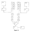
- FIG. 12 is a conceptual diagram of an embodiment of the invention, employing techniques of cross-correlation.
- This invention concerns the development of a device to provide a simple indication of the state of the airflow.
- the device provides flow state monitoring at selected locations on an air vehicle but the device could also be used on other vehicles types and to monitor industrial processes.
- the preferred embodiments use common circuit elements to perform operations directly on analogue flow sensor signals.
- the proposed device is therefore simple, cheap and uncomplicated to implement. Tens or hundreds of such devices may be required in service so the savings may be considerable. Additionally the device could be fabricated on an integrated circuit as part of the MEMS sensor and so be made small enough to be mounted with the sensor directly at the point of measurement. This has many advantages in terms of systems stability and immunity from interference or signal degradation.
- the functionality of the device could be extended to the detection of flow separation by dividing the input signals from adjacent sensors into several discrete frequency bands and comparing intermittency levels to provide a form of cross-correlation.
- FIGS. 1 to 6 are graphs taken from a measurement procedure, carried out on an array of hot flow film sensors as shown in FIG. 7 .
- FIG. 7 shows an integrated circuit chip 2 incorporating several air flow hot film sensors 4 , where air flow is measured by voltage change across the hot film.
- Each sensor comprises a hot film sense resistor 6 connected between vias 8 , which are connected to conductive terminal pillars 10 .
- the construction is described in more detail in WO2007/034240.
- the hot film is energised by an electrical circuit, described below, and the signal output from the sensor is in the form of an analogue voltage.
- the dimensions of the chip are 1350 ⁇ m long ⁇ 1500 ⁇ m wide ⁇ 250 ⁇ m thick. Thus the sensors are all located within a few millimeters of each other.
- the hot-film sensors were mounted on a leading-edge slat of a 2D high lift model in a wind tunnel and measurements taken at Mach 0.2 (68 m/s) giving a chord Reynolds number of ⁇ 3 million.
- the hot-film sampling frequency was 10 kHz, and a total of 1024 samples taken for each sensor, corresponding to just over 0.1 seconds.
- Data from hot-film sensors was collected, in the form of output voltages from each sensor. In FIGS. 1 to 3 , the mean voltage values have been subtracted from all the data supplied, so only the fluctuating component has been analysed.
- the flow over the slat is such that at below 5° the flow is laminar over the hot-film sensors. Above 5° and below 16° the flow is turbulent, and above 16° the flow is separated. The transitional flow state is not considered.
- the analogue output voltage is generally constant and not varying.
- the analogue output voltage for the case of turbulent flow is however extremely variable, resembling random noise.
- the analogue output voltage for the case of separated flow is generally similar to turbulent flow, but with signal amplitude much larger.
- the turbulent and separated flow voltage outputs have been analysed on the basis that flow is intermittent with high levels of turbulence interspersed with relatively quieter periods, but that laminar flow is essentially quiet all the time. Therefore, by filtering, smoothing and thresholding small time-slices of the signal so that the final result is either 0 (quiet) or 1 (noisy) and then calculating the proportion of time that the signal is noisy, a value called ‘intermittency’ can be calculated which varies between 0 and 1, with values close to zero being laminar, and values above zero but below 1 being turbulent or separated.
- FIG. 4 which plots intermittency value against angle of incidence of the leading-edge slat, that there is a step jump at an angle of 5°, where laminar flow changes to turbulent flow.
- intermittency provides a clear-cut way of differentiating between laminar and turbulent flow.
- FIG. 5 There is also a fairly clear change in intermittency values between turbulent and separated flows, as shown in FIG. 5 , where a step jump in intermittency value occurs at an angle of 16°.
- Intermittency rather than other measures such as standard deviation is that the critical values of Intermittency are not likely to change very much with changes in flow condition or noise, or sensor location. That is, for example it will probably always be the case that Intermittency will be less than 0.1 for laminar flow. It was also found, although not shown here that the choice of threshold value in the calculation of Intermittency was not particularly critical (variations of the value by a factor of 2 only made small differences), so any algorithm constructed in this way is likely to be very robust.
- Another measure which is employed in accordance with the invention is that of cross-correlation between neighbouring sensors, of an array of sensors. This is indicated graphically in FIG. 6 , for two adjacent sensors of the array of FIG. 7 . It will be noted that for turbulent flow, the cross-correlation is low, reflecting very small local disturbances in air flow, whereas for laminar and separated flow, which are characterised by more large scale flow states, the correlation is high. Thus a means is provided for distinguishing separated flow.
- FIG. 8 shows a schematic representation of part of the array of FIG. 7 wherein the flow sensors 4 are coupled to respective constant temperature bridge circuits 12 , which provide an analogue output voltage representing flow, to respective intermittency and cross-correlation analysis circuits 14 .
- the outputs 16 of the analysis circuits are supplied to an indicator circuit 18 , which provides an indication of whether the flow is in general separated.
- FIG. 9 An example of a constant temperature bridge circuit 12 is shown in FIG. 9 .
- Sense resistor 6 is connected in one arm of a bridge circuit 20 , which comprises fixed resistors 22 in the other three arms.
- An output taken from opposing nodes of the bridge circuit is supplied to the input of an operational amplifier 24 .
- the output of the amplifier 24 is fed via a diode 26 and an AC coupling capacitor 28 , to a circuit output 30 .
- a feedback path 32 from the diode 26 (the diode serving to stabilise the circuit) energises the bridge circuit 20 , and sense resistor 6 .
- the arrangement is such that when sense resistor 6 is exposed to airflow, and therefore cools, the value of its resistance changes by reason of the temperature coefficient of resistance. This creates a change in the output signal from the bridge circuit.
- the consequential output from amplifier 24 is fed back via path 32 to adjust the current supplied to the bridge 20 , and hence maintain the resistor at a constant temperature.
- FIG. 10 shows in conceptual form an arrangement for distinguishing turbulent flow from laminar and separated flow.
- the preferred embodiment uses MEMS hot film sensor 4 driving a constant temperature anemometer (CTA) with a frequency response up to 20 kHz.
- CTA constant temperature anemometer
- the anemometer output is an analogue voltage signal which is related transients in heat convection caused by small scale flow fluctuations in the flow boundary layer. This voltage can be calibrated to give an indication of the free stream velocity of the flow.
- a preferred embodiment includes a low pass filter which attenuates anything above the maximum response rate of the sensor/anemometer combination to reduce noise and disturbance from any high frequency oscillation of the anemometer circuitry.
- Other filters may be necessary depending on the application to limit the frequency range of the input signal.
- the filters could be of an active or passive nature and many common circuit elements exist for this purpose.
- the preferred embodiment would use simple resistor/capacitor networks for simplicity where this is possible.
- the filter output is fed through a capacitor to provide an AC coupled output, i.e. the output of the capacitor is nominally zero volts under steady conditions and under varying conditions a voltage appears across the capacitor that is proportional to the rate of change of the input signal.
- Rectification may be applied within the anemometer circuitry or in the signal conditioning circuitry.
- the elements 26 and 28 of the sense circuitry of FIG. 9 are employed for this purpose.
- This comprises a simple op-amp circuit or functionally similar unit.
- the sample period chosen to suit application, sensor frequency response and desired update intervals.
- a preferred embodiment uses 10-1000 ms.
- An AC coupled input is integrated over selected time period. At the end of the period a voltage appears at the output of the integrator which is related to the amount of noise on the signal for that period (the intermittency). After the output is sampled the integrator is reset and the next cycle begins. To establish the degree of intermittency the output of the signal conditioning stage is fed to an integrating amplifier for a predetermined period. At the end of this period the output voltage is fed to a sample and hold (S&H) circuit to store this voltage and provide input for the threshold detection stage until the next integration period is complete.
- S&H sample and hold
- Integrating amplifiers are a common circuit element often built around an operational amplifier. The integrating period will be selected according to the particular system under inspection but is likely to be of the order 1-1000 ms. After this period has elapsed the integrator will generate an output voltage that is proportional to the sum of the inputs over the period. This in turn will allow an indication to be made of the amount of noise detected during this period.
- An external clock may be required to synchronise the integrator and S&H stages, but in the preferred embodiment the two stages would be linked to provide this control.
- Integrator output is sampled at end of period and is held until the end of the next period. A similar result could also be achieved by latching the threshold detection stage.
- the S&H output voltage is fed to a threshold detection stage.
- This stage compares the voltage output with a pre-determined voltage level(s) set according to the needs of the system.
- the reference voltage(s) are set so that the output of the threshold stage changes state when the integrator voltage exceeds these point(s) and provides an output signal comprising a simple (i.e. single bit) indication of flow state.
- the use of multiple steps could allow a ‘level of confidence’ to be assigned to the state indication if desired.
- the threshold detection circuit could be made to ‘latch’ i.e. maintain its state until it receives a voltage outside of the currently held range so that the complexity of the integration/S&H stages could be reduced and if possible remove the need for a S&H stage altogether.
- Many common circuit elements could be used for this purpose but could include resistive bridges, zener diodes, transistor/diode junction voltage drop, Schmitt triggers etc.
- Threshold voltage(s) may be set according to application and may be derived from practical measurements.
- a single threshold may be used for laminar/turbulent transition indication, multiple thresholds may be used to assign a degree of confidence in the output.
- the output stage provides a signal or indication of flow state in a form suitable for the systems downstream of the device.
- Outputs may include fixed voltage/currents, characteristic frequencies etc.
- Threshold output may trigger a variety of output signals such as: Fixed output voltage level(s), characteristic frequencies or fixed currents for each state. Nature of output signal can be tailored to application, downstream hardware, transmission network etc.
- FIG. 11 shows a second arrangement for distinguishing turbulent flow from laminar flow, wherein the circuitry is made as simple as possible for cost reduction.
- a simple robust device that occupies very little space is desirable for airborne applications.
- a highly simplified but functionally equivalent circuit is desirable as a reduced component count will reduce the overall size and mass of each device. This would be especially important if 10s or 100s of devices are desired.
- the half wave rectified, AC coupled output of the signal conditioning stage could be passed through a simple series/parallel resistor capacitor network 64 . This would give a continuously integrated output.
- the integration period could be set by selecting the appropriate values for the resistors and capacitor to give the desired time constant (charging and discharging rates. This circuitry would not require additional external clock or S&H stages.
- the simple version of the device would use similar techniques to those already described with reference to FIG. 10 .
- FIG. 12 this shows a preferred embodiment of the invention, employing techniques of cross-correlation to distinguish between states of flow.
- Two adjacent sensors from the array of FIGS. 7 and 8 , together with associated bridge circuits, 412 A and 412 B are each coupled to a respective signal conditioning circuit 42 , which is similar to circuit 42 of FIG. 10 .
- Each circuit 42 is then fed to a bank of passband filters 701 - 705 , each having an adjacent frequency band, so that in this illustrative example, the signal bandwidth of 20 KHz is divided into five equal bands.
- the output from each passband filter is fed to a circuit 72 , which has an AC coupling and halfwave rectification function, to an integrating circuit 74 , which may be similar to that shown in FIG.
- circuits 74 (representing intermittency values of the signals) are compared in a comparator 80 , and the difference output value is applied to a threshold circuit 82 , which may be similar to circuit 50 of FIG. 10 , and which provides a single bit signal indicating whether there is correlation or not, i.e. separation or not.
- An output circuit 84 is provided for providing a flow output signal to a remote indicator device.
- Similar circuits are provided to process the outputs of the other passband filters, so that, in this embodiment, five different indicators are provided of correlation. These may be combined to provide an increased level of confidence in a transition from turbulent to separated flow.
- frequency bands may have an enhanced sensitivity to the transition, and these may be weighted more heavily in the combination with other frequency bands. Further similar comparisons may be generated with pairs of sensors which are next-nearest neighbour, etc., in the case a more extensive correlation may be desired.
- the circuit indicated in FIG. 12 for establishing correlation is designed to be simple, so as to reduce cost and size of integration. However, the complexity may be increased as desired, where a more accurate estimate of correlation is desired. For example the envelopes of the output signals over predetermined time intervals may be compared. Other mechanisms for establishing cross-correlation will be apparent to those skilled in the art. Further the more complex measures indicated in the description with reference to FIG. 10 to derive intermittency may be employed to replace the rectification and integration steps above.
Landscapes
- Physics & Mathematics (AREA)
- General Physics & Mathematics (AREA)
- Engineering & Computer Science (AREA)
- Aviation & Aerospace Engineering (AREA)
- Fluid Mechanics (AREA)
- Measuring Volume Flow (AREA)
- Aerodynamic Tests, Hydrodynamic Tests, Wind Tunnels, And Water Tanks (AREA)
Applications Claiming Priority (6)
| Application Number | Priority Date | Filing Date | Title |
|---|---|---|---|
| EP07270050.3 | 2007-09-12 | ||
| GB0717776A GB0717776D0 (en) | 2007-09-12 | 2007-09-12 | Fluid flow monitoring |
| EP07270050 | 2007-09-12 | ||
| GB0717776.9 | 2007-09-12 | ||
| EP07270050 | 2007-09-12 | ||
| PCT/GB2008/050810 WO2009034385A1 (fr) | 2007-09-12 | 2008-09-10 | Contrôle d'écoulement de fluide |
Publications (2)
| Publication Number | Publication Date |
|---|---|
| US20100275684A1 US20100275684A1 (en) | 2010-11-04 |
| US8061194B2 true US8061194B2 (en) | 2011-11-22 |
Family
ID=39963084
Family Applications (1)
| Application Number | Title | Priority Date | Filing Date |
|---|---|---|---|
| US12/377,467 Expired - Fee Related US8061194B2 (en) | 2007-09-12 | 2008-09-10 | Fluid flow monitoring |
Country Status (4)
| Country | Link |
|---|---|
| US (1) | US8061194B2 (fr) |
| EP (1) | EP2188640B1 (fr) |
| JP (1) | JP2010501879A (fr) |
| WO (1) | WO2009034385A1 (fr) |
Cited By (1)
| Publication number | Priority date | Publication date | Assignee | Title |
|---|---|---|---|---|
| US20160153825A1 (en) * | 2014-12-02 | 2016-06-02 | Tao Of Systems Integration, Inc. | Method and system for determining aerodynamic loads from downstream flow properties |
Families Citing this family (2)
| Publication number | Priority date | Publication date | Assignee | Title |
|---|---|---|---|---|
| JP5309818B2 (ja) * | 2008-09-10 | 2013-10-09 | トヨタ自動車株式会社 | 気流状態監視装置 |
| FR2944356B1 (fr) * | 2009-04-10 | 2011-06-24 | Thales Sa | Capteur optique de mesure de la vitesse d'un fluide le long d'une paroi et systeme comprenant plusieurs capteurs |
Citations (11)
| Publication number | Priority date | Publication date | Assignee | Title |
|---|---|---|---|---|
| US4061029A (en) | 1976-08-06 | 1977-12-06 | Nasa | Flow separation detector |
| US4727751A (en) | 1987-01-15 | 1988-03-01 | The United States Of America As Represented By The Administrator Of The National Aeronautics And Space Administration | Crossflow vorticity sensor |
| US4936146A (en) | 1988-06-07 | 1990-06-26 | The United States Of America As Represented By The Administrator Of The National Aeronautics And Space Administration | Method and apparatus for detecting laminar flow separation and reattachment |
| US5074147A (en) * | 1990-03-08 | 1991-12-24 | Analytical Services & Materials, Inc. | Flow rate measuring apparatus |
| US5218863A (en) | 1991-10-28 | 1993-06-15 | Mangalam Siva M | Instrumentation system for determining flow stagnation points |
| US5272915A (en) | 1992-01-23 | 1993-12-28 | The Boeing Company | Airflow sensing system |
| US6382024B1 (en) * | 2000-06-28 | 2002-05-07 | The United States Of America As Represented By The Administrator Of The National Aeronautics And Space Administration | Thermocouple boundary layer rake |
| US6471395B1 (en) * | 1999-02-18 | 2002-10-29 | Ifm Electronic Gmbh | Heat transfer monitoring/measuring device |
| WO2005022089A2 (fr) | 2003-09-02 | 2005-03-10 | Tao Of Systems Integration, Inc. | Procede et systeme permettant de localiser des indicateurs de caracteristiques d'ecoulement critique dans des regimes d'ecoulement tridimensionnels |
| WO2007034240A2 (fr) | 2005-09-20 | 2007-03-29 | Bae Systems Plc | Capteur |
| US7301352B1 (en) * | 2005-11-07 | 2007-11-27 | Sarma Garimella R | High sensitivity single or multi sensor interface circuit with constant voltage operation |
-
2008
- 2008-09-10 EP EP08788779.0A patent/EP2188640B1/fr active Active
- 2008-09-10 JP JP2009531927A patent/JP2010501879A/ja active Pending
- 2008-09-10 US US12/377,467 patent/US8061194B2/en not_active Expired - Fee Related
- 2008-09-10 WO PCT/GB2008/050810 patent/WO2009034385A1/fr not_active Ceased
Patent Citations (11)
| Publication number | Priority date | Publication date | Assignee | Title |
|---|---|---|---|---|
| US4061029A (en) | 1976-08-06 | 1977-12-06 | Nasa | Flow separation detector |
| US4727751A (en) | 1987-01-15 | 1988-03-01 | The United States Of America As Represented By The Administrator Of The National Aeronautics And Space Administration | Crossflow vorticity sensor |
| US4936146A (en) | 1988-06-07 | 1990-06-26 | The United States Of America As Represented By The Administrator Of The National Aeronautics And Space Administration | Method and apparatus for detecting laminar flow separation and reattachment |
| US5074147A (en) * | 1990-03-08 | 1991-12-24 | Analytical Services & Materials, Inc. | Flow rate measuring apparatus |
| US5218863A (en) | 1991-10-28 | 1993-06-15 | Mangalam Siva M | Instrumentation system for determining flow stagnation points |
| US5272915A (en) | 1992-01-23 | 1993-12-28 | The Boeing Company | Airflow sensing system |
| US6471395B1 (en) * | 1999-02-18 | 2002-10-29 | Ifm Electronic Gmbh | Heat transfer monitoring/measuring device |
| US6382024B1 (en) * | 2000-06-28 | 2002-05-07 | The United States Of America As Represented By The Administrator Of The National Aeronautics And Space Administration | Thermocouple boundary layer rake |
| WO2005022089A2 (fr) | 2003-09-02 | 2005-03-10 | Tao Of Systems Integration, Inc. | Procede et systeme permettant de localiser des indicateurs de caracteristiques d'ecoulement critique dans des regimes d'ecoulement tridimensionnels |
| WO2007034240A2 (fr) | 2005-09-20 | 2007-03-29 | Bae Systems Plc | Capteur |
| US7301352B1 (en) * | 2005-11-07 | 2007-11-27 | Sarma Garimella R | High sensitivity single or multi sensor interface circuit with constant voltage operation |
Non-Patent Citations (8)
| Title |
|---|
| European Search Report dated Apr. 17, 2008. |
| Lee et al., "Testing Unmanned Aerial Vehicle Airfoils" IEEE Instrumentation & Measurement Magazine, 2004, vol. 7, No. 3, pp. 32-37, XP-002504662. |
| Lennart Löfdahl et al., "MEMS applications in turbulence and flow control", XP-002475317, Progress in Aerospace Sciences, 1999 Elsevier Science Ltd, pp. 101-190. |
| Liu et al., "Detection of the Boundary-Layer Separation Point Based on the Flexible Sensor Arrays" Microsystem Technologies14, 2007, vol. 14, No. 1, pp. 1-6, XP-002504663. |
| Notification Concerning Transmittal of International Preliminary Report on Patentability (Forms PCT/IB/326 and PCT/IB/373) and the Written Opinion of the International Searching Authority (Form PCT/ISA/237) issued in corresponding International Application No. PCT/GB2008/050810 dated Mar. 25, 2010. |
| Notification of Transmittal of the International Search Report and the Written Opinion of the International Searching Authority (Forms PCT/ISA/220, PCT/ISA/210 and PCT/ISA/237) in the corresponding International Application No. PCT/GB2008/050810 dated Dec. 4, 2009. |
| S.M. Kumar et al., "MEMS Based Transducers for Boundary Layer Control", Department of Mechanical Engineering, Stanford University, 1999 IEEE, pp. 135-140. |
| United Kingdom Search Report dated Nov. 22, 2007. |
Cited By (2)
| Publication number | Priority date | Publication date | Assignee | Title |
|---|---|---|---|---|
| US20160153825A1 (en) * | 2014-12-02 | 2016-06-02 | Tao Of Systems Integration, Inc. | Method and system for determining aerodynamic loads from downstream flow properties |
| US9863974B2 (en) * | 2014-12-02 | 2018-01-09 | Tao Of Systems Integration, Inc. | Method and system for determining aerodynamic loads from downstream flow properties |
Also Published As
| Publication number | Publication date |
|---|---|
| EP2188640B1 (fr) | 2020-02-26 |
| EP2188640A1 (fr) | 2010-05-26 |
| WO2009034385A1 (fr) | 2009-03-19 |
| JP2010501879A (ja) | 2010-01-21 |
| US20100275684A1 (en) | 2010-11-04 |
Similar Documents
| Publication | Publication Date | Title |
|---|---|---|
| US7254520B2 (en) | Testing of wire systems and end devices installed in industrial processes | |
| US8322206B2 (en) | Apparatus and method for determining a fluid flow state | |
| US6973413B2 (en) | Instrument and process performance and reliability verification system | |
| JP6325004B2 (ja) | 改善されたセンサ診断を有するプロセス温度送信機 | |
| CN107036815A (zh) | 对轴承缺陷进行严重程度评估的方法和数据处理装置 | |
| CN101896807B (zh) | 用于表征空气流中荷电尘埃颗粒的尺寸分布的装置 | |
| CN108369109B (zh) | 用于监控至少两个冗余传感器的方法 | |
| US11187715B2 (en) | Multi-component fast-response velocity sensor | |
| US8061194B2 (en) | Fluid flow monitoring | |
| US20040068392A1 (en) | Control system and method for detecting plugging in differential pressure cells | |
| CA1251946A (fr) | Methode et dispositif de metrologie optique de l'ecoulement des fluides | |
| US20080190213A1 (en) | Zero Crossing Detection Of An Ultrasonic Signal With Variable Threshold Value | |
| CN109031996A (zh) | 用于现场设备的电流诊断 | |
| US10823595B2 (en) | Method for evaluating a frequency spectrum | |
| CN209485440U (zh) | 用于测量过程流体的流速的漩涡流量计 | |
| US20160266188A1 (en) | Device and Method for Detecting A Break Of At Least One Wired Sensor | |
| CN114018468A (zh) | 一种数字输出大气压力传感器 | |
| JPH10267803A (ja) | エアサンプリング式環境監視センサ | |
| CN117705657B (zh) | 一种颗粒粒径及对应颗粒数的算法 | |
| JP2004354280A (ja) | 導圧管詰まり検出器およびそれを内蔵した差圧・圧力伝送器 | |
| Chen et al. | Multi-channel signal processing method for vortex flowmeter based on parallel filtering | |
| Viana et al. | Reliable integration of thermal flow sensors into air data systems | |
| Jahanmiri | Turbulent-nonturbulent interface detection methods in transitional flows | |
| JPH03245018A (ja) | 計器信号による異常検出方法 | |
| DE102004017407A1 (de) | Luftprobenahmegerät mit Strömungsüberwachung |
Legal Events
| Date | Code | Title | Description |
|---|---|---|---|
| AS | Assignment |
Owner name: BAE SYSTEMS PLC, UNITED KINGDOM Free format text: ASSIGNMENT OF ASSIGNORS INTEREST;ASSIGNORS:GOUGH, DAVID WILLIAM;JOHNSON, GRAHAM ANDREW;WARSOP, CLYDE;AND OTHERS;SIGNING DATES FROM 20081013 TO 20081014;REEL/FRAME:022255/0824 |
|
| FEPP | Fee payment procedure |
Free format text: PAYOR NUMBER ASSIGNED (ORIGINAL EVENT CODE: ASPN); ENTITY STATUS OF PATENT OWNER: LARGE ENTITY |
|
| STCF | Information on status: patent grant |
Free format text: PATENTED CASE |
|
| FPAY | Fee payment |
Year of fee payment: 4 |
|
| MAFP | Maintenance fee payment |
Free format text: PAYMENT OF MAINTENANCE FEE, 8TH YEAR, LARGE ENTITY (ORIGINAL EVENT CODE: M1552); ENTITY STATUS OF PATENT OWNER: LARGE ENTITY Year of fee payment: 8 |
|
| FEPP | Fee payment procedure |
Free format text: MAINTENANCE FEE REMINDER MAILED (ORIGINAL EVENT CODE: REM.); ENTITY STATUS OF PATENT OWNER: LARGE ENTITY |
|
| LAPS | Lapse for failure to pay maintenance fees |
Free format text: PATENT EXPIRED FOR FAILURE TO PAY MAINTENANCE FEES (ORIGINAL EVENT CODE: EXP.); ENTITY STATUS OF PATENT OWNER: LARGE ENTITY |
|
| STCH | Information on status: patent discontinuation |
Free format text: PATENT EXPIRED DUE TO NONPAYMENT OF MAINTENANCE FEES UNDER 37 CFR 1.362 |
|
| FP | Lapsed due to failure to pay maintenance fee |
Effective date: 20231122 |