US8083007B2 - Electric power tool having speed reduction mechanism - Google Patents
Electric power tool having speed reduction mechanism Download PDFInfo
- Publication number
- US8083007B2 US8083007B2 US12/382,780 US38278009A US8083007B2 US 8083007 B2 US8083007 B2 US 8083007B2 US 38278009 A US38278009 A US 38278009A US 8083007 B2 US8083007 B2 US 8083007B2
- Authority
- US
- United States
- Prior art keywords
- operation lever
- unit
- pushed
- electric power
- motor
- Prior art date
- Legal status (The legal status is an assumption and is not a legal conclusion. Google has not performed a legal analysis and makes no representation as to the accuracy of the status listed.)
- Expired - Fee Related, expires
Links
Images




Classifications
-
- B—PERFORMING OPERATIONS; TRANSPORTING
- B25—HAND TOOLS; PORTABLE POWER-DRIVEN TOOLS; MANIPULATORS
- B25F—COMBINATION OR MULTI-PURPOSE TOOLS NOT OTHERWISE PROVIDED FOR; DETAILS OR COMPONENTS OF PORTABLE POWER-DRIVEN TOOLS NOT PARTICULARLY RELATED TO THE OPERATIONS PERFORMED AND NOT OTHERWISE PROVIDED FOR
- B25F5/00—Details or components of portable power-driven tools not particularly related to the operations performed and not otherwise provided for
- B25F5/001—Gearings, speed selectors, clutches or the like specially adapted for rotary tools
-
- Y—GENERAL TAGGING OF NEW TECHNOLOGICAL DEVELOPMENTS; GENERAL TAGGING OF CROSS-SECTIONAL TECHNOLOGIES SPANNING OVER SEVERAL SECTIONS OF THE IPC; TECHNICAL SUBJECTS COVERED BY FORMER USPC CROSS-REFERENCE ART COLLECTIONS [XRACs] AND DIGESTS
- Y10—TECHNICAL SUBJECTS COVERED BY FORMER USPC
- Y10T—TECHNICAL SUBJECTS COVERED BY FORMER US CLASSIFICATION
- Y10T74/00—Machine element or mechanism
- Y10T74/20—Control lever and linkage systems
- Y10T74/20012—Multiple controlled elements
- Y10T74/20018—Transmission control
- Y10T74/20085—Restriction of shift, gear selection, or gear engagement
- Y10T74/20098—Separate actuator to disengage restrictor
Definitions
- the present invention relates to an electric power tool, such as a drill driver, a disc saw or the like, which has a speed changing function performed by a speed reduction mechanism.
- This electric power tool includes a motor 101 as a driving power source, a speed reducer unit 102 for delivering the rotational power of the motor 101 at a reduced speed, a drive unit (not shown) for delivering the rotational power of the speed reducer unit 102 to a tip end tool, a resin-made housing 104 provided with a handle portion 104 a and arranged to contain the motor 101 and the speed reducer unit 102 therein, an operation lever 105 and a shift unit 105 a , both of which serve as a speed changing mechanism for changing the gear reduction ratio of the speed reducer unit 102 , the operation lever 105 being arranged in a position where it can be operated outside the housing 104 , a power switch 106 installed in the handle portion 104 a for switching on and off the power supply of the motor 101 , and a battery pack 107 engaged with the housing 104 for supplying electric power to the motor 101 .
- the operation lever 105 is designed to convert the tool operation state to a low-speed high-torque state in a high load condition (when the work load is heavy) but to a high-speed low-torque state in a low load condition (when the work load is light). This makes it possible for the electric power tool to perform a desired tightening task depending on the work load, thereby increasing the efficiency of work.
- the operation lever 105 may be operated during the work to change the gear reduction ratio. This may sometimes cause trouble to the electric power tool. More specifically, if the gear reduction ratio is changed with the operation lever 105 during the course of work, namely if the gear 102 a of the speed reducer unit 102 is shifted when in rotation, the mutually engageable gears may make contact with each other during their rotation and may be worn or damaged. This may be a cause of trouble in the electric power tool.
- the conventional solution to this problem is to increase the strength of gears, thereby preventing occurrence of trouble. In this case, however, the gears need to be made of high strength metal or formed into a big size, which leads to a problem of high cost and increased weight.
- the present invention provides an electric power tool capable of making it impossible to perform a speed changing operation until the pushing operation of an operation lever is detected, preventing itself from suffering from trouble which would otherwise occur due to the wear or damage of gears of a speed reducer unit caused by the speed changing operation performed during the course of work, enjoying enhanced reliability, reducing the strength required in the gears and assuring reduced cost and weight.
- the present invention further provides an electric power tool capable of making it possible to easily construct a slide restraint unit through the use of an operation lever and a housing, assuring increased operability, reliably restraining movement of the operation lever prior to a speed changing operation, preventing an erroneous operation which would otherwise occur when the operation lever is inadvertently touched, increasing the detection accuracy without having to use sensors in plural numbers, preventing wear of a detection member while prolonging the life span thereof, and preventing damage of precision electronic parts such as a sensor or a switch arranged below the operation lever even when a falling impact force or the like is applied to the operation lever.
- an electric power tool including: a motor as a driving power source for generating rotational power; a speed reducer unit arranged to deliver the rotational power of the motor and provided with two or more gears; a driving unit arranged to deliver the rotational power from the speed reducer unit to a tip end tool; a housing arranged to accommodate the motor, the speed reducer unit and the driving unit therein and provided with a handle portion; and a speed changing unit for changing a gear reduction ratio of the speed reducer unit, the speed changing unit arranged in such a position as to be operable outside the housing, wherein the speed changing unit comprises an operation lever slidingly operable in a speed changing direction when pushed, an operation detector unit for detecting the operation lever to control electric power supplied to the motor, a shift unit for changing the gear reduction ratio of the speed reducer unit in response to sliding movement of the operation lever, and a slide restraint unit for restraining the sliding operation of the operation lever until the operation detector unit detects the operation lever
- the slide restraint unit restrains the sliding operation of the operation lever and makes it impossible to perform a speed changing operation until the pushing operation of the operation lever is detected by the operation detector unit and until the electric power supplied to the motor is controlled to obtain the revolution number corresponding to the gear reduction ratio. This makes it possible to prevent the electric power tool from suffering from trouble which would otherwise occur due to the wear or damage of gears of the speed reducer unit caused by the speed changing operation performed during the course of work.
- the slide restraint unit may include a projection portion provided in one of mutually facing surfaces of the operation lever and the housing and a guide portion provided in the other surface, the projection portion and the guide portion being configured in such a manner as to restrain sliding movement of the operation lever in the speed changing direction when the push lever is in a non-pushed position but permit the sliding movement of the operation lever in the speed changing direction when the push lever is in a pushed position.
- the slide restraint unit may include a projection portion provided in one of mutually facing surfaces of the operation lever and the housing and a guide portion provided in the other surface, the projection portion and the guide portion being configured in such a manner as to restrain sliding movement of the operation lever in the speed changing direction when the push lever is in a non-pushed position but permit the sliding movement of the operation lever in the speed changing direction when the push lever is in a pushed position.
- the guide portion may include a slide operation groove extending in the speed changing direction and a pair of push operation grooves extending in a pushing direction of the operation lever from the opposite ends of the slide operation groove, the slide operation groove and the push operation grooves being continuously formed to have a substantially U-like shape. In this case, it is possible to simplify the configuration of the guide portion using the substantially U-shaped groove.
- the push operation grooves may be inclined at an obtuse angle with respect to the slide operation groove.
- the operation lever moves, when pushed, in the direction inclined at an obtuse angle with respect to the slide operation groove and not in the direction perpendicular to the slide operation groove. Therefore, the transition from the pushing operation to the sliding operation occurs smoothly, thereby enhancing the operability of the operation lever.
- the speed changing unit may further includes a resilient member for biasing the projection portion against the guide portion in a direction to restrain the movement of the operation lever and a restraint releasing unit for moving the projection portion to permit the movement of the operation lever when the operation lever is pushed.
- a resilient member for biasing the projection portion against the guide portion in a direction to restrain the movement of the operation lever
- a restraint releasing unit for moving the projection portion to permit the movement of the operation lever when the operation lever is pushed.
- the operation detector unit may be designed to detect the operation lever when the operation lever is in a generally middle position between a non-pushed position and a pushed position. In this case, if the operation lever is not pushed down by a predetermined amount, the operation detector unit fails to detect the pushing operation of the operation lever. This makes it possible to prevent an erroneous operation of the electric power tool which would otherwise occur when the operation lever is touched inadvertently.
- the operation lever may include an interrupter plate having a predetermined length in the speed changing direction, the operation detector unit including a sensor for optically detecting the interrupter plate when the operation lever is pushed.
- the operation detector unit including a sensor for optically detecting the interrupter plate when the operation lever is pushed.
- a single interrupter plate is sufficient to cover a plurality of pushing positions of the operation lever, because the interrupter plate extends in the speed changing direction. This eliminates the need to use sensors in plural numbers, while assuring reduced cost and weight.
- Use of the non-contact sensor assists in preventing wear of the interrupter plate and prolonging the life span thereof.
- the operation lever preferably has an operation surface depressed inwards from an outer surface of the housing. In this case, even if a falling impact force or the like is applied to the operation lever, the housing can first receive the impact force. This is because the operation surface of the operation lever is depressed. Therefore, it is possible to prevent damage of precision electronic parts such as a sensor or a switch arranged below the operation lever.
- the slide restraint unit restrains the sliding operation of the operation lever and makes it impossible to perform a speed changing operation until the pushing operation of the operation lever is detected to control the electric power supplied to the motor.
- This makes it possible to prevent the electric power tool from suffering from trouble which would otherwise occur due to the wear or damage of gears of the speed reducer unit caused by the speed changing operation performed during the course of work.
- it is possible to assure enhanced reliability and to reduce the strength required in the gears. Therefore, it becomes possible, for example, to change the material of gears from metal to resin, thereby reducing the cost and weight of the electric power tool.
- FIG. 1 is a side section view showing an electric power tool in accordance with one embodiment of the present invention
- FIG. 2 is an enlarged section view for explaining a speed changing mechanism employed in the electric power tool
- FIG. 3 is an exploded perspective view for explaining the speed changing mechanism employed in the electric power tool
- FIG. 4 is a perspective view showing the speed changing mechanism, with an operation lever removed for clarity;
- FIGS. 5A and 5B illustrate a projection portion kept in a non-pushed position, i.e., in a slide-restrained state, prior to changing the speed of the electric power tool;
- FIGS. 5C and 5D illustrate the projection portion moved to a pushed position and kept in a slide-permitted state prior to changing the speed of the electric power tool
- FIGS. 5E and 5F illustrate the projection portion slidingly operated to finish the speed changing operation
- FIGS. 5G and 5H illustrate the projection portion spring-biased into a non-pushed position and kept in a slide-restrained state after changing the speed of the electric power tool
- FIG. 6A is a perspective view corresponding to FIGS. 5A and 5B , which shows the projection portion kept in a non-pushed position, i.e., in a slide-restrained state, prior to changing the speed of the electric power tool
- FIG. 6B is a section view taken along line A-A in FIG. 6A
- FIG. 6C is a section view taken along line B-B in FIG. 6A
- FIG. 6D is a section view taken along line C-C in FIG. 6B ;
- FIG. 7A is a perspective view showing the projection portion pushed to a generally middle position but still kept in a slide-restrained state
- FIG. 7B is a section view taken along line D-D in FIG. 7A
- FIG. 7C is a section view taken along line E-E in FIG. 7A
- FIG. 7D is a section view taken along line F-F in FIG. 7B ;
- FIG. 8A is a perspective view corresponding to FIGS. 5C and 5D , which shows the projection portion moved to a pushed position and kept in a slide-permitted state
- FIG. 8B is a section view taken along line G-G in FIG. 8A
- FIG. 8C is a section view taken along line H-H in FIG. 8A
- FIG. 8D is a section view taken along line I-I in FIG. 8B ;
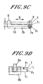
- FIG. 9A is a perspective view corresponding to FIGS. 5E and 5F , which shows the projection portion slidingly operated to finish the speed changing operation
- FIG. 9B is a section view taken along line J-J in FIG. 9A
- FIG. 9C is a section view taken along line K-K in FIG. 9A
- FIG. 9D is a section view taken along line L-L in FIG. 9B ;
- FIGS. 10A through 10H show another example of the guide portion of the speed changing mechanism
- FIGS. 10A and 10B illustrate the projection portion kept in a non-pushed position, i.e., in a slide-restrained state, prior to changing the speed of the electric power tool;
- FIGS. 10C and 10D illustrate the projection portion moved to a pushed position and kept in a slide-permitted state prior to changing the speed of the electric power tool
- FIGS. 10E and 10F illustrate the projection portion slidingly operated to finish the speed changing operation
- FIGS. 10G and 10H illustrate the projection portion spring-biased into a non-pushed position and kept in a slide-restrained state after changing the speed of the electric power tool
- FIG. 11A is a perspective view showing another example of the slide restraint unit, and FIG. 11B is a section view taken along line M-M in FIG. 11A ;
- FIG. 12A is a perspective view showing the slide restraint unit, with the push lever portion moved from the position shown in FIGS. 11A and 11B to a generally middle position, and FIG. 12B is a section view taken along line N-N in FIG. 12A ;
- FIG. 13A is a perspective view showing the slide restraint unit, with the push lever portion moved from the position shown in FIGS. 11A and 11B to a pushed position
- FIG. 13B is a section view taken along line P-P in FIG. 13A ;
- FIG. 14A is a perspective view showing still another example of the slide restraint unit, and FIG. 14B is a section view taken along line Q-Q in FIG. 14A ;
- FIG. 15 is a side section view showing a conventional electric power tool.
- FIGS. 16A and 16B are section views for explaining the conventional manner in which the tool operation state is converted from a low-speed high-torque state available in a high load condition (when the work load is heavy) to a high-speed low-torque state available in a low load condition (when the work load is light).
- the electric power tool 1 of the present embodiment essentially includes a motor 5 as a driving power source, a speed reducer unit 8 arranged to deliver the rotational power of the motor 5 and provided with two or more gears 8 a , a driving unit arranged to deliver the rotational power of the speed reducer unit 8 to a tip end tool, a bearing unit for rotatably supporting the driving unit, a housing 2 arranged to accommodate the motor 5 , the speed reducer unit 8 , the driving unit and the bearing unit therein and provided with a handle portion 2 a , and a speed changing mechanism 3 for changing the gear reduction ratio of the speed reducer unit 8 , the speed changing mechanism 3 being arranged in a position where it can be operated outside the housing 2 .
- reference numeral 106 designates a power switch for switching on and off the power supply of the motor 5 .
- a battery pack for supplying electric power to the motor 5 is omitted from illustration.
- the speed changing mechanism 3 is a slide-type operation switch 50 and is divided into an operation lever 4 (an upper layer portion) slidable in a speed changing direction R when in a pushed state and a lower layer portion 15 a as shown in FIG. 3 .
- the speed changing mechanism 3 includes an operation detector unit 6 for detecting the pushed position of the operation lever 4 and controlling the electric power supplied to the motor 5 so as to rotate the motor 5 at a revolution number corresponding to a gear reduction ratio, a shift unit 105 a (see FIG.
- Reference numeral 15 in the drawings designates a switch base.
- the speed changing direction R coincides with the axial direction of a rotation shaft of the motor 5 .
- the operation lever 4 is operated forwards and backwards as shown in FIGS. 2 and 3 and includes a slide lever portion 4 b slidable only in the speed changing direction R and a push lever portion 4 a that can be pushed downwards relative to the slide lever portion 4 b .
- a slide lever portion 4 b and the push lever portion 4 a are slidingly operated by pressing the operation surfaces 4 c with a finger, only the push lever portion 4 a is pushed downwards.
- a stepped portion 17 (see FIG. 5C and 7B ) for making it easy to slide the slide lever portion 4 b appear at the border between the operation surfaces 4 c .
- the push lever portion 4 a is biased upwards by a switch spring 18 .
- reference numeral 19 designates a guide shaft and reference numeral 60 designates a switch spring guide.
- An interrupter plate 6 a serving as a detection plate is installed to protrude downwards from the lower end of the push lever portion 4 a .
- the interrupter plate 6 a extends a predetermined length along the speed changing direction R and has, e.g., opening portions and non-opening portions (not shown) alternately arranged along the longitudinal direction thereof (i.e., the speed changing direction R).
- the operation surfaces 4 c of the operation lever 4 are depressed a predetermined depth W (see FIG. 2 ) from the outer surface of the housing 2 .
- a sensor stand 16 for holding a photo interrupter 6 b of the operation detector unit 6 is attached to the switch base 15 .
- the operation detector unit 6 detects the interrupter plate 6 a moved down together with the push lever portion 4 a when the latter is pushed. Using the detection results, the operation detector unit 6 controls the motor 5 in the below-mentioned manner so that the motor 5 can rotate at a revolution number corresponding to the gear reduction ratio.
- the slide restraint unit 7 restrains the operation lever 4 from performing the speed changing operation until the pushing operation of the push lever portion 4 a is detected by the photo interrupter 6 b .
- the slide restraint unit 7 of the present embodiment includes a pair of projection portions 7 a provided to the push lever portion 4 a and a pair of guide portions 7 b provided on the sliding surfaces of the housing 2 along which the operation lever 4 makes sliding movement.
- each of the guide portions 7 b includes, for example, a slide operation groove 10 extending in the speed changing direction R and a pair of push operation grooves 9 extending in a pushing direction S of the operation lever 4 from the opposite ends of the slide operation groove 10 .
- the slide operation groove 10 and the push operation grooves are continuously formed to have a substantially U-like shape.
- FIGS. 5A and 5B illustrate the projection portion 7 a kept in a slide-restrained state prior to changing the speed of the electric power tool 1 .
- FIGS. 5C and 5D illustrate the projection portion 7 a kept in a slide-permitted state.
- FIGS. 5E and 5F illustrate the projection portion 7 a slidingly operated to finish the speed changing operation.
- FIGS. 5G and 5H illustrate the projection portion 7 a spring-biased into the non-pushed position T and kept in the slide-restrained state after changing the speed of the electric power tool 1 .
- FIGS. 5A and 5B illustrate the projection portion 7 a kept in a slide-restrained state prior to changing the speed of the electric power tool 1 .
- FIGS. 5C and 5D illustrate the projection portion 7 a kept in a slide-permitted state.
- FIGS. 5E and 5F illustrate the projection portion 7 a slidingly operated to finish the speed changing operation.
- FIGS. 5G and 5H illustrate the projection portion 7 a spring-biased
- FIGS. 6A through 6D illustrate the positional relationship between the interrupter plate 6 a and the photo interrupter 6 b before the speed changing operation (or after the speed changing operation), which views correspond to FIGS. 5A and 5B (or FIGS. 5G and 5H ).
- reference letter “T” indicates the non-pushed position
- T 1 indicates the generally middle position where the interrupter plate 6 a is detectable by the photo interrupter 6 b
- P 1 indicates the push-in amount up to T 1
- T 2 indicates the pushed position where the sliding movement is permitted
- P 2 indicates the push-in amount up to T 2 .
- FIGS. 7A through 7D illustrate a state in which the push lever portion 4 a is pushed in up to the generally middle position T 1 where the interrupter plate 6 a is detectable by the photo interrupter 6 b .
- FIGS. 8A through 8D illustrate a state in which the push lever portion 4 a is pushed into a position where the sliding movement is permitted.
- FIGS. 9A through 9D illustrate the positional relationship between the interrupter plate 6 a and the photo interrupter 6 b after the speed changing operation, which views correspond to FIGS. 5E and 5F .
- the projection portion 7 a is moved down along the push operation groove 9 .
- the movement of the projection portion 7 a into the slide operation groove 10 is restrained when the push lever portion 4 a is in the generally middle position T 1 .
- the interrupter plate 6 a is detected by the photo interrupter 6 b .
- the photo interrupter 6 b detects whether the operation lever 4 is in a high-speed state or a low-speed state.
- a control unit (not shown) controls the electric power supplied to the motor 5 .
- the motor 5 When the high-speed state is detected, the motor 5 is converted from high speed rotation to low speed rotation. In contrast, when the low-speed state is detected, the motor 5 is converted from low speed rotation to high speed rotation.
- the operation lever 4 including the push lever portion 4 a and the slide lever portion 4 b is slidingly operated to perform the speed changing operation.
- the motor 5 When performing the speed changing operation, the motor 5 is already driven at a revolution number corresponding to the gear reduction ratio as mentioned above. Therefore, it is possible to prevent the gears of the speed reducer unit 8 from being worn or damaged by the mutual collision during their rotation, thereby avoiding occurrence of problems or trouble which would otherwise be caused by the speed changing operation performed during the course of work.
- the slide restraint unit 7 restrains the sliding movement of the operation lever 4 and makes it impossible to perform the speed changing operation until the pushing operation of the push lever portion 4 a of the operation lever 4 is detected by the operation detector unit 6 .
- the operation detector unit 6 performs its detection task in a reliable manner and the electric power supplied to the motor 5 is controlled so that the motor 5 can rotate at the revolution number corresponding to the gear reduction ratio. Therefore, it becomes possible to prevent the electric power tool from suffering from trouble which would otherwise occur due to the wear or damage of the gears 8 a of the speed reducer unit 8 caused by the speed changing operation performed during the course of work.
- the photo interrupter 6 b detects the push lever portion 4 a when the latter is in the generally middle position T 1 . In other words, the photo interrupter 6 b does not detect the push lever portion 4 a unless the latter is pushed down by a predetermined amount. This makes it possible to prevent an erroneous operation of the electric power tool which would otherwise occur when the push lever portion 4 a is touched inadvertently. Owing to the fact that the interrupter plate 6 a extends in the speed changing direction R, a single interrupter plate is sufficient to cover a plurality of pushing positions T 2 of the push lever portion 4 a .
- the photo interrupter 6 b This eliminates the need to use a sensor, e.g., the photo interrupter 6 b , in plural numbers, while assuring reduced cost and weight.
- Use of the non-contact sensor assists in preventing wear of the interrupter plate 6 a and prolonging the life span thereof. Since the photo interrupter 6 b is a non-contact sensor, it can be used for a long period of time.
- the lead wire through which to send a detection signal from the sensor to a power supply circuit of the motor 5 is kept stationary regardless of the operation of the operation lever 4 . This reduces the probability that the lead wire is flexed and eventually disconnected, thereby making it possible to increase reliability.
- the slide restraint unit 7 of the present embodiment includes the projection portions 7 a provided to the push lever portion 4 a of the operation lever 4 and the guide portions 7 b provided in the housing 2 .
- each of the guide portion 7 b includes the slide operation groove 10 extending in the speed changing direction R and the pair of push operation grooves 9 extending in the pushing direction S from the opposite ends of the slide operation groove 10 .
- the slide operation groove 10 and the push operation grooves are continuously formed to have a substantially U-like shape. This makes it possible simplify the configuration of the guide portion 7 b .
- the guide portions 7 b are provided in the housing 2 and the projection portions 7 a are provided to the operation lever 4 , it is possible to reduce the size of the slide-type operation switch 50 .
- the precision electronic parts e.g., the sensor such as the photo interrupter 6 b or the like and the switch such as the operation detector unit 6 or the like
- the operation surfaces 4 c of the operation lever 4 are depressed by a predetermined depth W (see FIG. 2 ). Therefore, the housing 2 can first receive the impact force. This makes it possible to prevent damage of the sensor.
- FIGS. 10A through 10H show another example of the substantially U-shaped grooves of the guide portion 7 b .
- a pair of push operation grooves 9 is inclined at an obtuse angle ⁇ with respect to a slide operation groove 10 .
- the remaining structures are the same as those of the embodiment shown in FIGS. 1 through 3 .
- the push operation grooves 9 extend continuously from the slide operation groove 10 in an upwardly diverging shape. As a result, when the push lever portion 4 a is pushed, it does not move down vertically but moves obliquely toward the slide operation groove 10 . Therefore, the transition from the pushing operation to the sliding operation occurs smoothly, thereby enhancing the operability of the operation lever 4 .
- FIGS. 11A , 11 B, 12 A, 12 B, 13 A and 13 B show another example of the guide portion 7 b .
- resilient bodies 12 for biasing the projection portions 7 a in a movement-restraining direction relative to the guide portions 7 b and restraint releasing units 13 for biasing the projection portions 7 a in a movement-permitting direction relative to the guide portions 7 b when the operation lever 4 is pushed.
- the remaining structures are the same as those of the embodiment shown in FIGS. 1 through 3 .
- a pair of left and right projection portions 7 a is arranged on the opposite sides of the sensor stand 16 as shown in FIG. 11B .
- the projection portions 7 a have the same structure.
- the sensor stand 16 has spring rests 70 arranged to support the tip ends of the coil springs.
- Triangular lug portions protrude upwards from the inner upper surfaces of the projection portions 7 a .
- Each of the lug portions has an outer tapering surface 13 a .
- Restraint releasing arms 13 b extend downwards from the lower opposite side surfaces of the push lever portion 4 a .
- the restraint releasing arms 13 b and the tapering surfaces 13 a of the lug portions constitute the restraint releasing units 13 .
- the projection portions 7 a are resiliently pressed against the guide portions 7 b by the coil springs as shown in FIG. 11B , thus restraining the sliding movement of the operation lever 4 .
- the push lever portion 4 a of the operation lever 4 is pushed, the restraint releasing arms 13 b are slidingly moved down over the tapering surfaces 13 a of the projection portions 7 a .
- the projection portions 7 a move away from the guide portions 7 b .
- the push lever portion 4 a reaches the generally middle position T 1 as shown in FIG. 12B , the interrupter plate 6 a is detected by the photo interrupter 6 b .
- the slide restraint unit 7 of this example is capable of bringing the projection portions 7 a from a movement-restrained state into a movement-permitted state in response to the pushing operation of the push lever portion 4 a of the operation lever 4 . This ensures that the transition from the pushing operation to the speed-changing sliding operation occurs in a smoother manner.
- Another advantage resides in that it is possible to easily construct the slide restraint unit 7 using the coil spring-biased projection portions 7 a provided in the operation lever 4 and the guide portions 7 b provided in the housing 2 .
- FIGS. 14A and 14B show an example in which the guide portions 7 b include grooves cut in the radial direction (i.e., the thickness direction) Y of the housing 2 .
- these grooves have a substantially U-like shape when seen from the inside of the housing 2 and are opened downwards.
- the remaining structures are the same as those of the embodiment shown in FIGS. 1 through 3 .
- projection portions 7 a protrude from the left and right end regions of the push lever portion 4 a .
- Each of the projection portions 7 a are formed into a generally L-like shape. The tip ends of the projection portions 7 a are inserted into the downwardly-opened guide portions 7 b of the housing 2 .
- the sensor stand 16 includes spring rests 70 provided at the left and right sides thereof. Coil springs as resilient bodies 12 for biasing the projection portions 7 a in a movement-restraining direction with respect to the guide portions 7 b are retained between the spring rests 70 and the lower surface of the push lever portion 4 a .
- the operation lever 4 of this example is in the non-pushed position T, the projection portions 7 a are resiliently pressed against the guide portions 7 b by the coil springs as shown in FIG. 14B , thus restraining the sliding movement of the operation lever 4 . If the push lever portion 4 a of the operation lever 4 is pushed, the coil springs are compressed and the tip ends of the projection portions 7 a are moved away from the guide portions 7 b .
- the interrupter plate 6 a is detected by the photo interrupter 6 b . If the push lever portion 4 a reaches the pushed position T 2 , the sliding movement of the projection portions 7 a relative to the guide portions 7 b is permitted so that the speed changing operation can be performed by slidingly operating the operation lever 4 .
- the slide restraint unit 7 of this example is capable of bringing the projection portions 7 a from a movement-restrained state into a movement-permitted state in response to the pushing operation of the push lever portion 4 a of the operation lever 4 .
- This ensures that the transition from the pushing operation to the speed-changing sliding operation occurs in a smoother manner.
- it is possible to easily construct the slide restraint unit 7 using the projection portions 7 a and the resilient bodies 12 provided to the operation lever 4 and the guide portions 7 b provided in the housing 2 . Owing to the fact that the guide portions 7 b are formed to extend in the radial direction (i.e., the thickness direction), it becomes easy to reduce the circumferential size of the housing 2 . Since the guide portions 7 b are opened downwards, it is possible to prevent dust from gathering in the guide portions 7 b.
- the operation lever 4 is divided into the slide lever portion 4 b and the push lever portion 4 a and only the push lever portion 4 a is pushed according to the foregoing embodiment, the present invention is not limited thereto.
- the operation lever 4 may be formed into a single piece so that the sliding operation can be performed while pushing the operation lever 4 as a whole.
- the photo interrupter 6 b is used as the operation detector unit 6 and the interrupter plate 6 a is used as the detected plate according to the foregoing embodiment, other sensors such as a magnetic sensor and the like may be used instead of the combination of the photo interrupter 6 b and the interrupter plate 6 a .
- a typical mechanical contact switch e.g., a tact switch, a limit switch or a micro switch.
- the speed changing direction R is the back-and-forth direction parallel to the axial direction D of the rotation shaft of the motor 5 according to the foregoing embodiment, the present invention is not limited thereto.
- the speed changing direction R may be the left-and-right direction perpendicular to the rotation shaft of the motor 5 .
- the guide portion 7 b may be a substantially U-shaped groove extending in the circumferential direction of the housing 2 . This assists in reducing the radial size of the housing 2 .
Landscapes
- Engineering & Computer Science (AREA)
- Mechanical Engineering (AREA)
- Portable Power Tools In General (AREA)
- Mechanical Control Devices (AREA)
Applications Claiming Priority (2)
| Application Number | Priority Date | Filing Date | Title |
|---|---|---|---|
| JP2008-102841 | 2008-04-10 | ||
| JP2008102841A JP4605242B2 (ja) | 2008-04-10 | 2008-04-10 | 電動工具 |
Publications (2)
| Publication Number | Publication Date |
|---|---|
| US20090255361A1 US20090255361A1 (en) | 2009-10-15 |
| US8083007B2 true US8083007B2 (en) | 2011-12-27 |
Family
ID=40679367
Family Applications (1)
| Application Number | Title | Priority Date | Filing Date |
|---|---|---|---|
| US12/382,780 Expired - Fee Related US8083007B2 (en) | 2008-04-10 | 2009-03-24 | Electric power tool having speed reduction mechanism |
Country Status (5)
| Country | Link |
|---|---|
| US (1) | US8083007B2 (de) |
| EP (1) | EP2108484B1 (de) |
| JP (1) | JP4605242B2 (de) |
| CN (1) | CN101554718B (de) |
| AT (1) | ATE516927T1 (de) |
Cited By (4)
| Publication number | Priority date | Publication date | Assignee | Title |
|---|---|---|---|---|
| US9108312B2 (en) | 2012-09-11 | 2015-08-18 | Milwaukee Electric Tool Corporation | Multi-stage transmission for a power tool |
| US9908228B2 (en) | 2012-10-19 | 2018-03-06 | Milwaukee Electric Tool Corporation | Hammer drill |
| US20250345914A1 (en) * | 2024-05-09 | 2025-11-13 | Makita Corporation | Power tool |
| US12587195B2 (en) | 2021-03-04 | 2026-03-24 | Snap-On Incorporated | Non-contact direction selector mechanism |
Families Citing this family (8)
| Publication number | Priority date | Publication date | Assignee | Title |
|---|---|---|---|---|
| CN102562958B (zh) * | 2010-12-29 | 2014-07-02 | 苏州宝时得电动工具有限公司 | 变速工具及其变速控制方法 |
| JP5764388B2 (ja) * | 2011-05-31 | 2015-08-19 | 佐鳥エス・テック株式会社 | 電動工具用トリガースイッチ |
| US10821591B2 (en) | 2012-11-13 | 2020-11-03 | Milwaukee Electric Tool Corporation | High-power cordless, hand-held power tool including a brushless direct current motor |
| CN103474272B (zh) * | 2013-09-04 | 2015-11-25 | 铁鎯电动工具有限公司 | 手持式电动工具轻触开关及其控制方法 |
| JP6481881B2 (ja) * | 2014-08-26 | 2019-03-13 | パナソニックIpマネジメント株式会社 | 電動工具 |
| JP6922221B2 (ja) * | 2016-12-29 | 2021-08-18 | マックス株式会社 | 結束機 |
| JP7027235B2 (ja) * | 2018-04-16 | 2022-03-01 | 株式会社マキタ | 電動工具 |
| CN110044411B (zh) * | 2019-04-01 | 2024-06-28 | 成都楠迪科技有限公司 | 一种可以同时测量扭力及转速的装置 |
Citations (24)
| Publication number | Priority date | Publication date | Assignee | Title |
|---|---|---|---|---|
| US3710873A (en) * | 1969-12-08 | 1973-01-16 | Desoutter Brothers Ltd | Impact wrench or screwdriver |
| FR2526348A1 (fr) | 1982-05-07 | 1983-11-10 | Black & Decker Inc | Perceuse electrique equipee d'un dispositif de commande de differentes fonctions |
| US4487270A (en) * | 1981-11-24 | 1984-12-11 | Black & Decker Inc. | Electric tool, particularly a handtool, with torque control |
| US4493223A (en) * | 1981-10-05 | 1985-01-15 | Matsushita Electric Works, Ltd. | Gear shifting speed change apparatus for a rotary electric tool |
| JPS61288909A (ja) | 1985-06-12 | 1986-12-19 | Makita Denki Seisakusho:Kk | 電動工具における変速装置 |
| JPS63185589A (ja) | 1987-01-26 | 1988-08-01 | 松下電工株式会社 | 電動工具 |
| US5056607A (en) * | 1989-05-25 | 1991-10-15 | Black & Decker Inc. | Mode change mechanism for power tools |
| US5083620A (en) * | 1989-12-28 | 1992-01-28 | Makita Electric Works, Ltd. | Cordless power driven tool |
| JPH0573343A (ja) | 1991-09-13 | 1993-03-26 | Nec Corp | データ転送処理装置 |
| JPH0580611A (ja) | 1991-09-24 | 1993-04-02 | Ricoh Co Ltd | 画像形成装置 |
| US5277527A (en) | 1991-03-29 | 1994-01-11 | Ryobi Limited | Torque adjustment device |
| US5339908A (en) | 1990-10-02 | 1994-08-23 | Ryobi Limited | Power tool |
| US5361853A (en) * | 1991-11-29 | 1994-11-08 | Ryobi Limited | Power tool |
| JPH07205050A (ja) | 1994-01-26 | 1995-08-08 | Matsushita Electric Works Ltd | 電動式回転工具 |
| US5738177A (en) * | 1995-07-28 | 1998-04-14 | Black & Decker Inc. | Production assembly tool |
| DE19919115A1 (de) | 1999-04-01 | 2000-11-02 | Mobiletron Electronics Co | Drehzahländerungs-Steuerstruktur für ein Elektrowerkzeug |
| US6536536B1 (en) * | 1999-04-29 | 2003-03-25 | Stephen F. Gass | Power tools |
| US20040188233A1 (en) | 2003-03-31 | 2004-09-30 | Armin Breitenmoser | Motor-driven hand-held tool with functional step display |
| US6836614B2 (en) * | 1993-07-06 | 2004-12-28 | Black & Decker Inc. | Electrical power tool having a motor control circuit for providing control over the torque output of the power tool |
| US6918449B2 (en) * | 2003-03-26 | 2005-07-19 | Matsushita Electric Works, Ltd. | Magnetic impact tool |
| US6971456B2 (en) * | 2002-09-10 | 2005-12-06 | Matsushita Electric Works, Ltd. | Electric power tool |
| JP2006150518A (ja) | 2004-11-30 | 2006-06-15 | Hitachi Koki Co Ltd | 電動工具 |
| WO2007025322A1 (en) | 2005-08-29 | 2007-03-08 | Demain Technology Pty Ltd | Power tool |
| US20090071673A1 (en) * | 2007-08-29 | 2009-03-19 | Positec Power Tools (Suzhou) Co., Ltd. | Power tool with signal generator |
Family Cites Families (1)
| Publication number | Priority date | Publication date | Assignee | Title |
|---|---|---|---|---|
| JP2585716Y2 (ja) * | 1992-03-13 | 1998-11-25 | 日立工機株式会社 | 電動工具の変速装置 |
-
2008
- 2008-04-10 JP JP2008102841A patent/JP4605242B2/ja not_active Expired - Fee Related
-
2009
- 2009-03-23 EP EP09004118A patent/EP2108484B1/de not_active Not-in-force
- 2009-03-23 AT AT09004118T patent/ATE516927T1/de not_active IP Right Cessation
- 2009-03-24 US US12/382,780 patent/US8083007B2/en not_active Expired - Fee Related
- 2009-03-31 CN CN200910132920.8A patent/CN101554718B/zh not_active Expired - Fee Related
Patent Citations (25)
| Publication number | Priority date | Publication date | Assignee | Title |
|---|---|---|---|---|
| US3710873A (en) * | 1969-12-08 | 1973-01-16 | Desoutter Brothers Ltd | Impact wrench or screwdriver |
| US4493223A (en) * | 1981-10-05 | 1985-01-15 | Matsushita Electric Works, Ltd. | Gear shifting speed change apparatus for a rotary electric tool |
| US4487270A (en) * | 1981-11-24 | 1984-12-11 | Black & Decker Inc. | Electric tool, particularly a handtool, with torque control |
| FR2526348A1 (fr) | 1982-05-07 | 1983-11-10 | Black & Decker Inc | Perceuse electrique equipee d'un dispositif de commande de differentes fonctions |
| JPS61288909A (ja) | 1985-06-12 | 1986-12-19 | Makita Denki Seisakusho:Kk | 電動工具における変速装置 |
| JPS63185589A (ja) | 1987-01-26 | 1988-08-01 | 松下電工株式会社 | 電動工具 |
| US5056607A (en) * | 1989-05-25 | 1991-10-15 | Black & Decker Inc. | Mode change mechanism for power tools |
| US5083620A (en) * | 1989-12-28 | 1992-01-28 | Makita Electric Works, Ltd. | Cordless power driven tool |
| US5339908A (en) | 1990-10-02 | 1994-08-23 | Ryobi Limited | Power tool |
| US5277527A (en) | 1991-03-29 | 1994-01-11 | Ryobi Limited | Torque adjustment device |
| JPH0573343A (ja) | 1991-09-13 | 1993-03-26 | Nec Corp | データ転送処理装置 |
| JPH0580611A (ja) | 1991-09-24 | 1993-04-02 | Ricoh Co Ltd | 画像形成装置 |
| US5361853A (en) * | 1991-11-29 | 1994-11-08 | Ryobi Limited | Power tool |
| US6836614B2 (en) * | 1993-07-06 | 2004-12-28 | Black & Decker Inc. | Electrical power tool having a motor control circuit for providing control over the torque output of the power tool |
| JPH07205050A (ja) | 1994-01-26 | 1995-08-08 | Matsushita Electric Works Ltd | 電動式回転工具 |
| US5738177A (en) * | 1995-07-28 | 1998-04-14 | Black & Decker Inc. | Production assembly tool |
| DE19919115A1 (de) | 1999-04-01 | 2000-11-02 | Mobiletron Electronics Co | Drehzahländerungs-Steuerstruktur für ein Elektrowerkzeug |
| US6186709B1 (en) | 1999-04-01 | 2001-02-13 | Mobiletron Electronics Co., Ltd. | Speed change control structure for an electric tool |
| US6536536B1 (en) * | 1999-04-29 | 2003-03-25 | Stephen F. Gass | Power tools |
| US6971456B2 (en) * | 2002-09-10 | 2005-12-06 | Matsushita Electric Works, Ltd. | Electric power tool |
| US6918449B2 (en) * | 2003-03-26 | 2005-07-19 | Matsushita Electric Works, Ltd. | Magnetic impact tool |
| US20040188233A1 (en) | 2003-03-31 | 2004-09-30 | Armin Breitenmoser | Motor-driven hand-held tool with functional step display |
| JP2006150518A (ja) | 2004-11-30 | 2006-06-15 | Hitachi Koki Co Ltd | 電動工具 |
| WO2007025322A1 (en) | 2005-08-29 | 2007-03-08 | Demain Technology Pty Ltd | Power tool |
| US20090071673A1 (en) * | 2007-08-29 | 2009-03-19 | Positec Power Tools (Suzhou) Co., Ltd. | Power tool with signal generator |
Non-Patent Citations (1)
| Title |
|---|
| The Japanese Office Action dated Dec. 15, 2009 and English summary thereof. |
Cited By (7)
| Publication number | Priority date | Publication date | Assignee | Title |
|---|---|---|---|---|
| US9108312B2 (en) | 2012-09-11 | 2015-08-18 | Milwaukee Electric Tool Corporation | Multi-stage transmission for a power tool |
| US9908228B2 (en) | 2012-10-19 | 2018-03-06 | Milwaukee Electric Tool Corporation | Hammer drill |
| US10888986B2 (en) | 2012-10-19 | 2021-01-12 | Milwaukee Electric Tool Corporation | Hammer drill |
| US11345009B2 (en) | 2012-10-19 | 2022-05-31 | Milwaukee Electric Tool Corporation | Hammer drill |
| US11826892B2 (en) | 2012-10-19 | 2023-11-28 | Milwaukee Electric Tool Corporation | Hammer drill |
| US12587195B2 (en) | 2021-03-04 | 2026-03-24 | Snap-On Incorporated | Non-contact direction selector mechanism |
| US20250345914A1 (en) * | 2024-05-09 | 2025-11-13 | Makita Corporation | Power tool |
Also Published As
| Publication number | Publication date |
|---|---|
| CN101554718A (zh) | 2009-10-14 |
| ATE516927T1 (de) | 2011-08-15 |
| JP4605242B2 (ja) | 2011-01-05 |
| EP2108484B1 (de) | 2011-07-20 |
| CN101554718B (zh) | 2012-08-22 |
| EP2108484A1 (de) | 2009-10-14 |
| JP2009248280A (ja) | 2009-10-29 |
| US20090255361A1 (en) | 2009-10-15 |
Similar Documents
| Publication | Publication Date | Title |
|---|---|---|
| US8083007B2 (en) | Electric power tool having speed reduction mechanism | |
| US7980320B2 (en) | Electric power tool with gear reduction unit | |
| US8713806B2 (en) | Power tool | |
| US6742601B2 (en) | Battery powered tools | |
| US8739417B2 (en) | Circular saw | |
| US8167183B2 (en) | Electric drive tool | |
| US8453901B2 (en) | Electric drive tool | |
| US8564236B2 (en) | Power tool | |
| US8469115B2 (en) | Electrical power tool | |
| JP2019155533A (ja) | ネジ締め工具 | |
| JP7513499B2 (ja) | ベルトサンダ | |
| EP2762278A2 (de) | Elektrisches Werkzeug | |
| CN212706493U (zh) | 电动工具 | |
| JP2009212004A (ja) | 磁気検出式入力装置 | |
| JP4950933B2 (ja) | スライド式操作スイッチ | |
| US6880420B2 (en) | Automatic control device for a motorized vehicle gearbox | |
| JP2022046337A (ja) | トリガスイッチ | |
| TW200623181A (en) | Lever driven electrical component | |
| WO2026023638A1 (ja) | 作業機 | |
| JP2023005977A (ja) | 作業機 | |
| JP2017095011A (ja) | シフトスイッチ装置 | |
| JP2023027867A (ja) | 光センサを用いたトリガースイッチを備えた電動工具 | |
| JP5020644B2 (ja) | 電動工具のスイッチ | |
| JP2022089588A (ja) | トリガスイッチ |
Legal Events
| Date | Code | Title | Description |
|---|---|---|---|
| AS | Assignment |
Owner name: PANASONIC ELECTRIC WORKS OC., LTD., JAPAN Free format text: ASSIGNMENT OF ASSIGNORS INTEREST;ASSIGNORS:INAGAKI, KENICHIRO;SEKINO, FUMIAKI;YAMADA, YUTAKA;REEL/FRAME:022484/0290;SIGNING DATES FROM 20090210 TO 20090213 Owner name: PANASONIC ELECTRIC WORKS OC., LTD., JAPAN Free format text: ASSIGNMENT OF ASSIGNORS INTEREST;ASSIGNORS:INAGAKI, KENICHIRO;SEKINO, FUMIAKI;YAMADA, YUTAKA;SIGNING DATES FROM 20090210 TO 20090213;REEL/FRAME:022484/0290 |
|
| FEPP | Fee payment procedure |
Free format text: PAYOR NUMBER ASSIGNED (ORIGINAL EVENT CODE: ASPN); ENTITY STATUS OF PATENT OWNER: LARGE ENTITY |
|
| STCF | Information on status: patent grant |
Free format text: PATENTED CASE |
|
| FPAY | Fee payment |
Year of fee payment: 4 |
|
| FEPP | Fee payment procedure |
Free format text: MAINTENANCE FEE REMINDER MAILED (ORIGINAL EVENT CODE: REM.); ENTITY STATUS OF PATENT OWNER: LARGE ENTITY |
|
| LAPS | Lapse for failure to pay maintenance fees |
Free format text: PATENT EXPIRED FOR FAILURE TO PAY MAINTENANCE FEES (ORIGINAL EVENT CODE: EXP.); ENTITY STATUS OF PATENT OWNER: LARGE ENTITY |
|
| STCH | Information on status: patent discontinuation |
Free format text: PATENT EXPIRED DUE TO NONPAYMENT OF MAINTENANCE FEES UNDER 37 CFR 1.362 |
|
| FP | Lapsed due to failure to pay maintenance fee |
Effective date: 20191227 |