US8220401B2 - Sewing machine for covering chain stitch - Google Patents
Sewing machine for covering chain stitch Download PDFInfo
- Publication number
- US8220401B2 US8220401B2 US12/567,101 US56710109A US8220401B2 US 8220401 B2 US8220401 B2 US 8220401B2 US 56710109 A US56710109 A US 56710109A US 8220401 B2 US8220401 B2 US 8220401B2
- Authority
- US
- United States
- Prior art keywords
- thread
- cover thread
- looper
- top cover
- needles
- Prior art date
- Legal status (The legal status is an assumption and is not a legal conclusion. Google has not performed a legal analysis and makes no representation as to the accuracy of the status listed.)
- Expired - Fee Related, expires
Links
Images


Classifications
-
- D—TEXTILES; PAPER
- D05—SEWING; EMBROIDERING; TUFTING
- D05B—SEWING
- D05B1/00—General types of sewing apparatus or machines without mechanism for lateral movement of the needle or the work or both
- D05B1/08—General types of sewing apparatus or machines without mechanism for lateral movement of the needle or the work or both for making multi-thread seams
-
- D—TEXTILES; PAPER
- D05—SEWING; EMBROIDERING; TUFTING
- D05B—SEWING
- D05B1/00—General types of sewing apparatus or machines without mechanism for lateral movement of the needle or the work or both
- D05B1/02—General types of sewing apparatus or machines without mechanism for lateral movement of the needle or the work or both for making single-thread seams
-
- D—TEXTILES; PAPER
- D05—SEWING; EMBROIDERING; TUFTING
- D05B—SEWING
- D05B53/00—Thread- or cord-laying mechanisms; Thread fingers
-
- D—TEXTILES; PAPER
- D05—SEWING; EMBROIDERING; TUFTING
- D05B—SEWING
- D05B57/00—Loop takers, e.g. loopers
- D05B57/02—Loop takers, e.g. loopers for chain-stitch sewing machines, e.g. oscillating
Definitions
- the present invention relates to a sewing machine for covering chain stitch having a cover thread looper which arranges a top cover thread on a surface of a cloth in which stitches are formed by a plurality of needles.
- a sewing machine for covering chain stitch described in Japanese Patent Publication Laid-Open No. 2008-142498 is widely employed.
- a stitch formed by the sewing machine for covering chain stitch has excellent elasticity and strength.
- the sewing machine for covering chain stitch includes a cover thread looper.
- the cover thread looper arranges a top cover thread on a surface of a cloth on which stitches are formed by a plurality of needles, so as to make the top cover thread regularly intertwine with the stitches.
- the top cover thread arranged by the cover thread looper makes appearance of the stitch excellent.
- FIG. 1 is an enlarged perspective view showing a needle area of a conventional sewing machine for covering chain stitch.
- the sewing machine for covering chain stitch includes four needles 41 a to 41 d arranged on a plane which substantially intersects with a sending direction (front and back direction) of a cloth 200 .
- the needles 41 a to 41 d are fixed to a lower end of a needle rod 4 through a needle stopper 45 .
- the needles 41 a to 41 d move upward and downward by vertical motion of the needle rod 4 .
- the needles 41 a to 41 d are provided with needle holes at their lower ends. Needle threads 42 a to 42 d are supplied from above so as to pass through the needle holes of the needles 41 a to 41 d, respectively, from the front side as shown in the drawing.
- the sewing machine for covering chain stitch includes a looper (not shown) in a bed which supports a lower side of the cloth 200 .
- the looper holds a looper thread and moves forward and rearward in an arranging direction (right and left direction) of the needles 41 a to 41 d.
- the forward and rearward movement of the looper is generated in synchronization with vertical movements of the needles 41 a to 41 d, and a stitch is formed on the cloth 200 .
- the sewing machine for covering chain stitch further includes a cover thread looper 90 and a cover thread guide 93 arranged on one side (right side) in the arranging direction of the needles 41 a to 41 d.
- the cover thread looper 90 is an arc member which swings in the right and left direction on the front side of the needles 41 a to 41 d .
- the cover thread looper 90 includes a thread hook 90 a inside of the tip end.
- a top cover thread 100 is hooked on the thread hook 90 a.
- the cover thread guide 93 includes a guide hole 93 a which is long in the front and back direction, and the guide hole 93 a is located on the upper side of the cover thread looper 90 .
- a front end of the guide hole 93 a is located frontward of positions where the needles 41 a to 41 d are arranged, and a back end of the guide hole 93 a is located backward of the positions where the needles 41 a to 41 d are arranged.
- the top cover thread 100 is supplied from above, passes through a small hole 44 a of the thread-guide member 44 provided on the needle stopper 45 as shown in the drawing.
- the top cover thread 100 is connected to the cloth 200 through a guide hole 93 a of the cover thread guide 93 .
- the top cover thread 100 is hooked on the thread hook 90 a of the cover thread looper 90 swinging below the cover thread guide 93 , and arranged on a surface of the cloth 200 .
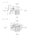
- FIG. 2A and FIG. 2B are explanatory diagrams showing movement of the cover thread looper 90 .
- the cover thread looper 90 swings between a receding position shown in FIG. 2A and a advancing position shown in FIG. 2B .
- the thread hook 90 a is opposed to a back side of the top cover thread 100 passing near a front end of the guide hole 93 a. If the advancing motion of the cover thread looper 90 is started, the top cover thread 100 is hooked on the thread hook 90 a on the tip end of the cover thread looper 90 , the cover thread looper 90 goes around to a front side of the needles 41 a to 41 d while the cover thread looper 90 is pulled out from the guide hole 93 a , and the cover thread looper 90 reaches the advancing position shown in FIG. 2B .
- top cover thread 100 An appropriate tension is applied to the top cover thread 100 .
- the top cover thread 100 slides in the guide hole 93 a as the cover thread looper 90 is pulled out. Then, the top cover thread 100 moves to a back end of the guide hole 93 a, and the top cover thread 100 is extended between the guide hole 93 a and the thread hook 90 a.
- the needles 41 a to 41 d are fixed to the needle stopper 45 such that their lower ends are opposing to the cover thread guide 93 and are sequentially positioned upward.
- the top cover thread 100 pulled out by the cover thread looper 90 is located above the lower ends of the left two needles 41 a and 41 b, and under the lower ends of the right two needles 41 c and 41 d. Therefore, the top cover thread 100 comes into contact with a front portion of the needle 41 b and is bent as shown in FIG. 2B .
- the top cover thread 100 passes on the back side of the needle 41 c and is continued to the guide hole 93 a of the cover thread guide 93 . In this state, the top cover thread 100 is pressed on a surface of the cloth 200 by the needle threads 42 a to 42 d of the needles 41 a to 41 d, and is arranged on the surface.
- FIG. 3 is a perspective view showing a covering chain stitch as viewed from a front of the cloth. As shown in the drawing, the seams of the needle threads 42 a to 42 d are arranged on the surface of the cloth 200 .
- the covering chain stitch is formed in an arrangement that the top cover thread 100 regularly waves across the seams.
- a hollow arrow shows a sending direction of the cloth 200 .
- the “thread-stitching” is a sewing failure generated when a needle pierces through the top cover thread 100 arranged on the cloth 200 as shown with a symbol “A” in FIG. 3 .
- the “stitch skipping” is a sewing failure generated when the top cover thread 100 comes across a seam at a wrong position as shown with a symbol “B” in FIG. 3 .
- FIG. 4 is an explanatory diagram showing a mechanism of generation of sewing failure.
- FIG. 4 shows a positional relationship between the needle thread 42 d of the needle 41 d located at the leftmost position in FIG. 2 , the cloth 200 and the top cover thread 100 from side.
- the needle 41 d in the drawing is located at the top dead center (the uppermost position), the needle thread 42 d extends diagonally downward backwardly from a needle hole of the needle 41 d, and the needle thread 42 d is continued to the cloth 200 (stitch on the cloth 200 ) in a state where an appropriate tension is applied to the needle thread 42 d.
- the top cover thread 100 is located under the tip end of the needle 41 d and behind the needle 41 d as described above.
- the needle thread 42 d extending from the needle 41 d toward the cloth 200 may come into contact with the top cover thread 100 located at such a position from behind.
- the tension of the top cover thread 100 is generally smaller than that of the needle thread 42 d.
- the top cover thread 100 is pushed by the needle thread 42 d which contacts the top cover thread 100 from behind, and the top cover thread 100 is moved frontward as shown with broken lines in FIG. 4 .
- This movement influences even a position behind the needle 41 c which is adjacent to the needle 41 d .
- the top cover thread 100 may pass directly below the needle 41 c as shown with broken lines in FIG. 2B or may pass through a location in front of the needle 41 c.
- the lowering needle 41 c pierces through the top cover thread 100 , and the “thread-stitching” is generated.
- the top cover thread 100 passes frontward the needle 41 c, the lowering needle 41 c passes behind the top cover thread 100 and the “stitch skipping” is generated.
- the present invention has been accomplished in view of the above circumstances, and it is an object of the invention to provide a sewing machine for covering chain stitch capable of reliably arranging a top cover thread at a predetermined position on a surface of a cloth, and capable of forming a stitch having excellent appearance without generating sewing failures such as “thread-stitching” and “stitch skipping”.
- a sewing machine for covering chain stitch of the first invention includes a plurality of needles arranged in a direction intersecting with a sending direction, a cover thread guide which is arranged on one side of the needles in an arrangement direction and which has a guide hole being long in a front and back direction, and a cover thread looper which is located below the cover thread guide and which moves frontward and backward so as to come across a front side of the needles, in which a top cover thread passing through the guide hole is caught by the advancing cover thread looper and is pulled out, the top cover thread being guided through the guide hole and being arranged on a surface of the cloth, wherein the sewing machine for covering chain stitch further includes a thread push member that moves frontward and backward at a location above the cover thread guide in association with the cover thread looper, pushes by the backward movement the top cover thread which passes through the guide hole, and forcibly moves the top cover thread to a back side of the guide hole.
- the thread push member moves frontward and backward at a location above the cover thread guide in association with the cover thread looper.
- the thread push member moves backward, it presses the top cover thread which passes through a guide hole of the cover thread guide.
- the top cover thread is forcibly moved to a location near a back end of the guide hole by the pushing action of the thread push member, the top cover thread keeps the moved position against a tension of the needle thread which comes into contact the top cover thread from behind, and the top cover thread is reliably arranged at a predetermined position on a surface of a cloth.
- the thread push member of the first invention is mounted on a drive shaft of the cover thread looper, and the sewing machine for covering chain stitch further includes a swinging rod swinging in accordance with repetitive pivot movement of the drive shaft.
- the thread push member is mounted on the top cover shaft which drives the cover thread looper, and a drive system for the cover thread looper and the thread push member are commonly used, and the object can be achieved with a simple structure.
- FIG. 1 is an enlarged perspective view showing needles of a conventional sewing machine for covering chain stitch
- FIGS. 2A and 2B are explanatory diagrams showing conventional movement of a cover thread looper
- FIG. 3 is a conventional perspective view showing a covering chain stitch as viewed from a surface of a cloth
- FIG. 4 is a conventional explanatory diagram showing a generation of sewing failure
- FIG. 5 is a perspective view showing an outward appearance of a sewing machine for covering chain stitch according to the present invention.
- FIG. 6 is a schematic perspective view showing the entire structure of a transmission mechanism to a needle rod
- FIG. 7 is a side view showing the transmission mechanism to the needle rod
- FIG. 8 is a perspective view showing a movement-converting mechanism and a top cover transmission mechanism
- FIG. 9 is an exploded perspective view showing the movement-converting mechanism and the top cover transmission mechanism
- FIG. 10 is an enlarged perspective view showing needles of the sewing machine for covering chain stitch of the present invention.
- FIG. 11 is an explanatory diagram showing movement of the needle, the cover thread looper and the thread push member
- FIG. 12 is an explanatory diagram showing movement of the needle, the cover thread looper and the thread push member
- FIG. 13 is an explanatory diagram showing movement of the needle, the cover thread looper and the thread push member
- FIG. 14 is an explanatory diagram showing movement of the needle, the cover thread looper and the thread push member
- FIG. 15 is an explanatory diagram showing movement of the needle, the cover thread looper and the thread push member
- FIG. 16 is an explanatory diagram showing movement of the needle, the cover thread looper and the thread push member.
- FIGS. 17A and 17B are explanatory diagrams showing the cover thread looper and the thread push member.
- FIG. 5 is a perspective view showing an outward appearance of a sewing machine for covering chain stitch according to the present invention.
- FIG. 6 is a schematic perspective view showing the entire structure of a transmission mechanism to a needle rod.
- FIG. 7 is a side view showing the transmission mechanism shown in FIG. 6 .
- the sewing machine for covering chain stitch shown in the drawings is constituted as a longitudinal cylindrical sewing machine in which a small-diameter cylindrical bed 2 projects from a lower portion of one side of a sewing machine body 1 , and a sewing machine arm 3 projects substantially in parallel to the cylindrical bed 2 above the cylindrical bed 2 on the same side.
- a needle plate 20 is provided on an upper surface of a tip end of the cylindrical bed 2 .
- a sending device and a looper (both not shown) are provided in the cylindrical bed 2 below the needle plate 20 .
- a needle rod 4 is supported on a tip end of the sewing machine aim 3 .
- Four needles 41 a to 41 d are mounted on a lower end of the needle rod 4 projecting downward from the sewing machine arm 3 through a needle stopper 45 (see FIG. 10 ).
- a press bar (not shown) is supported on the tip end of the sewing machine arm 3 . The press bar projects downward of the sewing machine arm 3 behind the needle rod 4 (on the side of a base end of the cylindrical bed 2 ), and a press metal 21 is mounted on this projecting end.
- the cloth 200 (see FIGS. 11 to 16 ) is sandwiched between the press metal 21 and the needle plate 20 , and is sent from a tip end side (front side) to a base end side (back side) of the cylindrical bed 2 by the operation of the sending device.
- the needles 41 a to 41 d are arranged in a direction intersecting with the sending direction of the cloth 200 .
- the needles 41 a to 41 d move upward and downward in synchronization with the sending movement of the cloth 200 .
- the looper moves forward and rearward in the arranging direction (right and left direction) of the needles 41 a to 41 d in synchronization with the sending movement of the cloth 200 .
- the cloth 200 is sewed by the operations of the needles 41 a to 41 d and the looper.
- a sewing machine main shaft 5 is provided at a lower portion in the sewing machine body 1 .
- the sewing machine main shaft 5 extends in the right and left direction.
- the sewing machine main shaft 5 is connected to an output end of the sewing machine motor (not shown) by a drive belt 51 which is wound around a drive pulley 50 of one end (left end).
- the sewing machine main shaft 5 is rotated and driven by the sewing machine motor through the drive belt 51 and the drive pulley 50 .
- a transmission shaft 6 is provided at an upper portion in the sewing machine body 1 .
- the transmission shaft 6 is substantially in parallel to the sewing machine main shaft 5 , and the transmission shaft 6 is supported at a position corresponding to a height of the projecting portion of the sewing machine arm 3 .
- a transmission belt 60 wound around a transmission pulley 61 of one end (right end) the transmission shaft 6 is connected to a transmission pulley 62 of the other end (right end) of the sewing machine main shaft 5 .
- the transmission shaft 6 is rotated around a center axis by rotation of the sewing machine main shaft 5 transmitted through the transmission belt 60 .
- a needle rod drive shaft 7 is provided near the needle rod 4 inside a tip end of the sewing machine aim 3 .
- the needle rod drive shaft 7 is in almost parallel to the sewing machine main shaft 5 and the transmission shaft 6 .
- the needle rod drive shaft 7 is connected to a transmission pulley 62 arranged on an end of the transmission shaft 6 on the same side in a side by side relation with the transmission pulley 61 by a transmission belt 70 wound around a transmission pulley 71 on one end (right end).
- the needle rod drive shaft 7 rotates around a center axis by rotation of the transmission shaft 6 transmitted through the transmission belt 70 .
- the needle rod drive shaft 7 is connected to the needle rod 4 through a movement-converting mechanism 8 shown in FIGS. 8 and 9 .
- the needle rod drive shaft 7 is connected to a top cover device 9 b by a top cover transmission mechanism 9 a shown in FIGS. 8 and 9 .
- FIG. 8 is a perspective view showing the movement-converting mechanism 8 and the top cover transmission mechanism 9 a.
- FIG. 9 is an exploded perspective view showing the movement-converting mechanism 8 and the top cover transmission mechanism 9 a.
- the movement-converting mechanism 8 includes a crank arm 80 and a needle swing aim 81 .
- a needle rod crank 72 having a predetermined eccentricity is provided at an intermediate portion of the needle rod drive shaft 7 as shown in FIG.
- a base end of the crank arm 80 is connected to the needle rod crank 72 .
- An intermediate portion of the needle swing arm 81 is supported by a support shaft 82 which is in parallel to the needle rod drive shaft 7 so that the needle swing arm 81 can swing around an axis of the support shaft 82 .
- One end of the needle swing arm 81 extending toward the needle rod drive shaft 7 is connected to a tip end of the crank arm 80 through a connecting shaft 83 , and the other end of the needle swing arm 81 extending toward the needle rod 4 is connected to a needle rod holder 40 fixed to an intermediate portion of the needle rod 4 through short links 84 .
- a needle stopper 45 is fixed to a lower end of the needle rod 4 .
- the four needles 41 a to 41 d are mounted on the needle stopper 45 in this order from left to right.
- a retainer 43 is mounted on the needle stopper 45 on the left side of the needle 41 a.
- the needles 41 a to 41 d and the retainer 43 mounted on the needle stopper 45 are moved upward and downward between the top dead center and the bottom dead center by the vertical movement of the needle rod 4 .
- the needles 41 a to 41 d moving upward and downward sew a cloth on the needle plate 20 in cooperation with the looper which moves forward and rearward.
- the top cover device 9 b includes a top cover shaft 9 , a cover thread looper 90 and a thread push member 94 .
- the top cover shaft 9 is supported by bearing bushes 91 and 92 at upper and lower walls of the sewing machine arm 3 , and the top cover shaft 9 can rotate around a vertical axis.
- the cover thread looper 90 includes a shaft portion extending downward from the looper stage 99 and a curved portion which is continued to a lower end of the shaft portion and curved into an arc shape on a plane (plane which is substantially in parallel to the needle plate 20 ) substantially intersecting with an axial direction.
- the curved portion of the cover thread looper 90 is provided with a thread hook 90 a which inwardly projects near the tip end.
- the thread push member 94 is mounted on a holding stage 95 which is integrally provided on the looper stage 99 .
- the thread push member 94 includes a connecting shaft 94 a extending downward from the holding stage 95 , and a swinging rod 94 b which is formed by bending a lower portion of the connecting shaft 94 a substantially at right angles and which is substantially in parallel to the needle plate 20 .
- the top cover transmission mechanism 9 a transmits rotation movement of the needle rod drive shaft 7 to the top cover shaft 9 , and repeatedly turns the top cover shaft 9 .
- the top cover transmission mechanism 9 a includes a top cover lever 92 b, a swing arm 91 a, a top cover crank arm 92 a and a connection link 98 a.
- the top cover lever 92 b is supported by a support shaft 82 which is common to the needle swing arm 81 . Thus, the top cover lever 92 b can swing around the support shaft 82 .
- a top cover crank 73 having a predetermined eccentricity is provided on an intermediate portion of the needle rod drive shaft 7 as shown in FIG. 9 .
- the top cover crank 73 is arranged on one side of the needle rod crank 72 in a side by side relation.
- a base portion of the top cover crank arm 92 a is connected to the top cover crank 73 .
- a tip end of the top cover crank arm 92 a extending frontward is connected to one end of the top cover lever 92 b.
- this connected position can be adjusted along a long hole 92 c formed in the top cover lever 92 b.
- a connection pin 97 a extending leftward substantially in parallel to the support shaft 82 is provided on the other end of the top cover lever 92 b extending downward from the supported position by the support shaft 82 .
- the swing aim 91 a is located between upper and lower bearing bushes 91 and 92 and fixed to the top cover shaft 9 . As shown in FIG. 9 , a tip end of the swing arm 91 a is provided with a connection pin 96 a which extends downward.
- the swing arm 91 a and the top cover lever 92 b are connected to each other through a connection link 98 a. Both ends of the connection link 98 a are fitted to the connection pin 96 a and the connection pin 97 a.
- the connection link 98 a and the connection pin 97 a are fitted to each other through a ball joint 97 b.
- top cover lever 92 b swings around the support shaft 82 , and one period of the top cover lever 92 b corresponds to one rotation of the needle rod drive shaft 7 .
- This swinging angle can be changed by adjusting a connected position between the top cover crank arm 92 a and the top cover lever 92 b.
- the swinging movement of the top cover lever 92 b generated in this manner is transmitted to the swing arm 91 a through the connection link 98 a, and the top cover shaft 9 on which the swing arm 91 a is mounted repeatedly turns through an angle corresponding to the swinging angle of the top cover lever 92 b.
- FIG. 10 is an enlarged perspective view showing the needles of the sewing machine for covering chain stitch of the present invention.
- the cover thread looper 90 mounted on the top cover shaft 9 is located on the right side of the rightmost needle 41 d as shown in FIG. 10 .
- the cover thread looper 90 swings in accordance with the repetitive pivot movement of the top cover shaft 9 .
- a tip end of the curved portion having the thread hook 90 a advances until it reaches a left position with respect to the left needle 41 a as coming across a front side of the arrangement positions of the needles 41 a to 41 d.
- a cover thread guide 93 similar to a guide of the conventional sewing machine for covering chain stitch is arranged at a position on the cover thread looper 90 .
- the cover thread guide 93 is mounted on a front surface of the sewing machine aim 3 as extending downward.
- the cover thread guide 93 includes a plate portion formed by bending a lower end thereof such as to intersect with the top cover shaft 9 (in parallel to the needle plate 20 ).
- the plate portion is provided with a guide hole 93 a which is long in the front and back direction.
- a front end of the guide hole 93 a is located frontward of the arrangement positions of the needles 41 a to 41 d, and a back end of the guide hole 93 a is located backward of the arrangement positions of the needles 41 a to 41 d.
- the swinging rod 94 b of the thread push member 94 mounted on the top cover shaft 9 is located at a higher position than the plate portion of the cover thread guide 93 , and a tip end of the swinging rod 94 b is located frontward of a front end of the guide hole 93 a.
- the swinging rod 94 b of the thread push member 94 located in such a position swings in synchronization with the cover thread looper 90 in accordance with repetitive pivot movement of the top cover shaft 9 .
- the swinging movement of the swinging rod 94 b is generated in a range which passes through an upper side of the guide hole 93 a provided in the cover thread guide 93 and reaching a back end portion from a front side frontward of a front end of the guide hole 93 a.
- FIGS. 11 to 16 are explanatory diagrams for explaining a series of movement of the needles 41 a to 41 d, the cover thread looper 90 and the thread push member 94 .
- FIG. 17A and FIG. 17B are explanatory diagrams showing the movement of the cover thread looper 90 and the thread push member 94 .
- FIG. 17A corresponds to FIG. 11
- FIG. 17B corresponds to FIG. 13 .
- the needles 41 a to 41 d move upward and downward between the top dead center and the bottom dead center, and the cover thread looper 90 and the thread push member 94 swing between the receding position shown in FIG. 17A and the advancing position shown in FIG 17 B in synchronization with the vertical movements of the needles 41 a to 41 d .
- the needles 41 a to 41 d are near the bottom dead center, and penetrate the cloth 200 as shown in FIG. 11 .
- the needles 41 a to 41 d are near the top dead center, and are separated above the cloth 200 by a predetermined distance as shown in FIG. 13 .
- the needles 41 a to 41 d are provided at their lower ends with needle holes.
- the needle threads 42 a to 42 d are supplied from above as shown in the drawings, and they respectively pass through the needle holes of the needles 41 a to 41 d from front side.
- the thread-guide member 44 extending upward of a front end of the guide hole 93 a of the cover thread guide 93 is mounted on a front surface of the needle stopper 45 which fixes the needles 41 a to 41 d.
- a small hole 44 a is formed and vertically penetrates at an extended end of the thread-guide member 44 .
- the top cover thread 100 is supplied from above, passes through the small hole 44 a formed at the thread-guide member 44 as shown in the drawing, passes through the guide hole 93 a of the cover thread guide 93 and is continued to the cloth 200 .
- the top cover thread 100 is hooked on the thread hook 90 a of the cover thread looper 90 swinging below the guide hole 93 a , and is arranged on the surface of the cloth 200 , as will be described later.
- the thread push member 94 swings above the guide hole 93 a and influences the top cover thread 100 , as will be described later.
- the thread hook 90 a is opposed to a back side of the top cover thread 100 passing near a front end of the guide hole 93 a as shown in FIG. 17A .
- the top cover thread 100 is hooked on the tip end thread hook 90 a.
- the top cover thread 100 is pulled out from the guide hole 93 a, goes around front of the needles 41 a to 41 d, and reaches the advancing position shown in FIG. 17B .
- An appropriate tension is applied to the top cover thread 100 .
- the top cover thread 100 slides in the guide hole 93 a by the tension, moves backward of the guide hole 93 a, and is tightened between the position after the movement and the thread hook 90 a.
- the cover thread looper 90 advances as shown with a solid arrow in
- FIG. 12 With this movement, the top cover thread 100 is hooked on the tip end thread hook 90 a, the top cover thread 100 is pulled out from the guide hole 93 a while the top cover thread 100 goes to front of the arrangement positions of the needles 41 a to 41 d from the side of the right needle 41 d.
- the swinging rod 94 b of the thread push member 94 swings as shown with a hollow arrow in FIG. 12 , and approaches the top cover thread 100 passing through the guide hole 93 a of the cover thread guide 93 from front.
- the needles 41 a to 41 d move upward together with the thread-guide member 44 , as shown by an arrow of broken line in FIG. 12 .
- the cover thread looper 90 When the needles 41 a to 41 d move upward and reach the top dead center, the cover thread looper 90 reaches the advancing position shown in FIGS. 13 and 17B . At that time, the thread hook 90 a of the cover thread looper 90 is located on a left and front side of the needle 41 a.
- the swinging rod 94 b of the thread push member 94 influences the top cover thread 100 above the guide hole 93 a, and the swinging rod 94 b pushes the top cover thread 100 backward.
- the top cover thread 100 is guided to a location near the back end of the guide hole 93 a by this pushing action, and the top cover thread 100 is prevented from moving frontward from this position.
- the top cover thread 100 can keeps a stable tightened attitude between a location near the back end of the guide hole 93 a and the thread hook 90 a of the cover thread looper 90 located at the advancing position. This tightened attitude is not varied by an external force applied to the top cover thread 100 backward.
- Positions of the lower ends of the four needles 41 a to 41 d are different from each other as described above.
- the lower ends of the left two needles 41 a and 41 b are located below the top cover thread 100
- the lower ends of the right two needles 41 c and 41 d are located above the top cover thread 100 . Therefore, the top cover thread 100 tightened between the guide hole 93 a and the thread hook 90 a comes into contact with a front portion of the needle 41 b and bends as shown in FIG. 17B , and the top cover thread 100 passes a back side of the needle 41 c and is continued to the guide hole 93 a of the cover thread guide 93 .
- the top cover thread 100 is further bent back at the thread hook 90 a , diagonally comes across a back side of the arrangement position of the needles 41 a to 41 d, and is continued to a stitch which was previously formed on the cloth 200 .
- the needles 41 a to 41 d move downward as shown by an arrow of broke line in FIG. 14 .
- the needle threads 42 a to 42 d and the top cover thread 100 are intertwined with each other.
- the cover thread looper 90 swings rightward as shown by a solid arrow in FIG. 14 , and the top cover thread 100 comes out from the thread hook 90 a.
- the swinging rod 94 b of the thread push member 94 swings frontward as shown by a hollow arrow in FIG. 14 .
- the pressure of the top cover thread 100 is released.
- the needles 41 a to 41 d further move downward and penetrate the cloth 200 as shown in FIG. 15 , return to the bottom dead center as shown in FIG. 16 , and press the top cover thread 100 against the surface of the cloth 200 .
- the cover thread looper 90 keeps swinging rightward, the thread hook 90 a of the cover thread looper 90 moves away from the front positions of the needles 41 a to 41 d, and returns to the receding position as shown in FIG. 16 .
- the swinging rod 94 b of the thread push member 94 keeps swinging frontward, moves away from the front end of the guide hole 93 a and returns to the receding position as shown in FIG. 16 .
- the needle thread 42 d extending from the needle hole of the right needle 41 d to the cloth 200 may come into contact with the top cover thread 100 passing the back side of the needles 41 a to 41 d from behind and may apply a frontward pushing force, as explained using FIG. 4 , when the needles 41 a to 41 d are at the top dead center.
- the top cover thread 100 is pushed backward by the swinging rod 94 b of the thread push member 94 , and is prevented from moving away from the vicinity of the back end of the guide hole 93 a formed in the cover thread guide 93 . Therefore, the top cover thread 100 is not moved frontward by a force applied from the needle thread 42 d which comes into contact from behind, and the tightened attitude of the top cover thread 100 is not varied.
- the thread push member 94 is mounted on the top cover shaft 9 which drives the cover thread looper 90 , and the thread push member 94 functions as the top cover shaft 9 and the drive mechanism and thus, the object can be achieved with a simple structure.
- the sewing machine for covering chain stitch having the four needles 41 a to 41 d is explained in this embodiment, the present invention can also be applied to a sewing machine for covering chain stitch having two or three needles or a multi-needle sewing machine for covering chain stitch having five or more needles and a similar effect can be obtained.
- the top cover thread passing through the guide hole of the cover thread guide is pressed by the thread push member which moves frontward and backward in association with the cover thread looper, and forcibly moves it backward of the guide hole.
- the top cover thread is arranged at a predetermined position on the surface of the cloth without being affected by contact with the needle thread. Therefore, it is possible to prevent the sewing failure such as “thread-stitching” and “stitch skipping” from being generated, and covering chain stitches can stably be formed with excellent appearance.
Landscapes
- Engineering & Computer Science (AREA)
- Textile Engineering (AREA)
- Sewing Machines And Sewing (AREA)
Applications Claiming Priority (2)
| Application Number | Priority Date | Filing Date | Title |
|---|---|---|---|
| JP2008248637A JP4725864B2 (ja) | 2008-09-26 | 2008-09-26 | 偏平縫いミシン |
| JP2008-248637 | 2008-09-26 |
Publications (2)
| Publication Number | Publication Date |
|---|---|
| US20100077949A1 US20100077949A1 (en) | 2010-04-01 |
| US8220401B2 true US8220401B2 (en) | 2012-07-17 |
Family
ID=42047953
Family Applications (1)
| Application Number | Title | Priority Date | Filing Date |
|---|---|---|---|
| US12/567,101 Expired - Fee Related US8220401B2 (en) | 2008-09-26 | 2009-09-25 | Sewing machine for covering chain stitch |
Country Status (5)
| Country | Link |
|---|---|
| US (1) | US8220401B2 (ja) |
| JP (1) | JP4725864B2 (ja) |
| KR (1) | KR101158515B1 (ja) |
| CN (2) | CN101684590B (ja) |
| TW (1) | TWI479061B (ja) |
Cited By (2)
| Publication number | Priority date | Publication date | Assignee | Title |
|---|---|---|---|---|
| US20160032507A1 (en) * | 2014-08-04 | 2016-02-04 | Toyoda Gosei Co., Ltd. | Stitch line forming method |
| US9297100B1 (en) * | 2014-11-05 | 2016-03-29 | Hsuan-Yi Wu | Six-needle eight-thread stitch configuration |
Families Citing this family (9)
| Publication number | Priority date | Publication date | Assignee | Title |
|---|---|---|---|---|
| JP4725864B2 (ja) * | 2008-09-26 | 2011-07-13 | ヤマトミシン製造株式会社 | 偏平縫いミシン |
| CN102514042B (zh) * | 2012-01-11 | 2013-01-09 | 宁波舒普机电科技有限公司 | 一种冲孔机的冲刀选择结构 |
| CN103572516B (zh) * | 2012-08-09 | 2015-07-29 | 曾贤长 | 缝纫机上环缝勾驱动结构 |
| CN103510277B (zh) * | 2013-09-18 | 2016-01-20 | 宁波凯信服饰股份有限公司 | 多针平缝机 |
| JP6406903B2 (ja) | 2014-07-15 | 2018-10-17 | 株式会社ゴールドウイン | 縫目構造 |
| GB2532023A (en) * | 2014-11-05 | 2016-05-11 | Hsuan-Yi Wu | Six-needle eight-thread stitch configuration |
| CN104846561B (zh) * | 2015-04-17 | 2017-11-14 | 苏州琼派瑞特电子科技有限公司 | 一种反手绷缝机 |
| CN104846567B (zh) * | 2015-04-17 | 2017-07-11 | 苏州琼派瑞特电子科技有限公司 | 一种反手绷缝机用花线结构 |
| JP7371915B2 (ja) * | 2020-03-26 | 2023-10-31 | オルガン針株式会社 | 偏平縫いミシン用針および偏平縫いミシンを使用した縫製方法 |
Citations (8)
| Publication number | Priority date | Publication date | Assignee | Title |
|---|---|---|---|---|
| US1405855A (en) * | 1917-07-18 | 1922-02-07 | Union Special Machine Co | Stitch-forming mechanism for sewing machines |
| US1855254A (en) * | 1928-07-19 | 1932-04-26 | Union Special Machine Co | Cross thread laying mechanism for sewing machines |
| JPS4994456A (ja) | 1972-10-20 | 1974-09-07 | ||
| JPH06327857A (ja) | 1993-05-17 | 1994-11-29 | Union Special Corp | カバー糸を備えた三針ステッチ |
| US6553927B1 (en) * | 2001-10-29 | 2003-04-29 | Hosei Mishin Seizo Kabushiki Kaisha | Spreader driving device of a sewing machine |
| US20060107885A1 (en) * | 2004-11-16 | 2006-05-25 | Shogo Hasegawa | Upper decorative stitching device |
| JP2006192189A (ja) | 2005-01-17 | 2006-07-27 | Juki Corp | ミシン及び縫い目の形成方法 |
| JP2008142498A (ja) | 2006-12-07 | 2008-06-26 | Yamato Sewing Mach Co Ltd | 上飾り機構付きミシン |
Family Cites Families (3)
| Publication number | Priority date | Publication date | Assignee | Title |
|---|---|---|---|---|
| GB2268940B (en) * | 1992-06-23 | 1996-06-05 | Ngai Keung Metal & Plastic Man | Sewing machine |
| CN2179395Y (zh) * | 1993-12-31 | 1994-10-12 | 湖南工业缝纫机厂 | 一种双针链式缝纫机 |
| JP4725864B2 (ja) * | 2008-09-26 | 2011-07-13 | ヤマトミシン製造株式会社 | 偏平縫いミシン |
-
2008
- 2008-09-26 JP JP2008248637A patent/JP4725864B2/ja active Active
-
2009
- 2009-09-04 TW TW098129843A patent/TWI479061B/zh active
- 2009-09-24 KR KR1020090090721A patent/KR101158515B1/ko active Active
- 2009-09-25 CN CN2009102044145A patent/CN101684590B/zh active Active
- 2009-09-25 CN CN2009201749197U patent/CN201525940U/zh not_active Expired - Lifetime
- 2009-09-25 US US12/567,101 patent/US8220401B2/en not_active Expired - Fee Related
Patent Citations (11)
| Publication number | Priority date | Publication date | Assignee | Title |
|---|---|---|---|---|
| US1405855A (en) * | 1917-07-18 | 1922-02-07 | Union Special Machine Co | Stitch-forming mechanism for sewing machines |
| US1855254A (en) * | 1928-07-19 | 1932-04-26 | Union Special Machine Co | Cross thread laying mechanism for sewing machines |
| JPS4994456A (ja) | 1972-10-20 | 1974-09-07 | ||
| US3882806A (en) | 1972-10-20 | 1975-05-13 | Rimoldi C Spa Virginio | Cover thread pulling and take-up device for multineedle sewing machines |
| JPH06327857A (ja) | 1993-05-17 | 1994-11-29 | Union Special Corp | カバー糸を備えた三針ステッチ |
| US5383414A (en) | 1993-05-17 | 1995-01-24 | Union Special Corporation | Apparatus for making a three needle stitch with cover thread |
| US5544604A (en) * | 1993-05-17 | 1996-08-13 | Union Special Corporation | Three needle stitch with cover thread |
| US6553927B1 (en) * | 2001-10-29 | 2003-04-29 | Hosei Mishin Seizo Kabushiki Kaisha | Spreader driving device of a sewing machine |
| US20060107885A1 (en) * | 2004-11-16 | 2006-05-25 | Shogo Hasegawa | Upper decorative stitching device |
| JP2006192189A (ja) | 2005-01-17 | 2006-07-27 | Juki Corp | ミシン及び縫い目の形成方法 |
| JP2008142498A (ja) | 2006-12-07 | 2008-06-26 | Yamato Sewing Mach Co Ltd | 上飾り機構付きミシン |
Cited By (3)
| Publication number | Priority date | Publication date | Assignee | Title |
|---|---|---|---|---|
| US20160032507A1 (en) * | 2014-08-04 | 2016-02-04 | Toyoda Gosei Co., Ltd. | Stitch line forming method |
| US9879366B2 (en) * | 2014-08-04 | 2018-01-30 | Toyoda Gosei Co., Ltd. | Stitch line forming method |
| US9297100B1 (en) * | 2014-11-05 | 2016-03-29 | Hsuan-Yi Wu | Six-needle eight-thread stitch configuration |
Also Published As
| Publication number | Publication date |
|---|---|
| KR20100035609A (ko) | 2010-04-05 |
| JP4725864B2 (ja) | 2011-07-13 |
| US20100077949A1 (en) | 2010-04-01 |
| CN101684590B (zh) | 2013-04-03 |
| CN201525940U (zh) | 2010-07-14 |
| TWI479061B (zh) | 2015-04-01 |
| TW201013000A (en) | 2010-04-01 |
| KR101158515B1 (ko) | 2012-06-20 |
| CN101684590A (zh) | 2010-03-31 |
| JP2010075543A (ja) | 2010-04-08 |
Similar Documents
| Publication | Publication Date | Title |
|---|---|---|
| US8220401B2 (en) | Sewing machine for covering chain stitch | |
| CN101778971B (zh) | 单线锁型缝纫手缝线迹形成方法以及缝纫机 | |
| WO2007088708A1 (ja) | 1本糸錠縫化ハンドステッチ形成方法及びミシン | |
| JP6045392B2 (ja) | ミシン | |
| US11326284B2 (en) | Double-needle lockstitch sewing machine | |
| CN103194860B (zh) | 纽扣孔锁边缝纫机 | |
| JP3872487B2 (ja) | 間歇ステッチ縫いミシン | |
| JP4296560B2 (ja) | 二重環縫いミシンの針糸案内装置 | |
| JP2001314681A (ja) | ミシン | |
| JP4196378B2 (ja) | ミシンの針受け装置 | |
| KR100723025B1 (ko) | 미싱 | |
| CN102653902B (zh) | 缝纫机 | |
| JP2009011595A (ja) | ミシン | |
| KR100648477B1 (ko) | 미싱의 바늘받이 장치 | |
| JP5545505B2 (ja) | 1本糸錠縫化ハンドステッチミシン | |
| US814642A (en) | Stitch-forming mechanism for sewing-machines. | |
| JP4615235B2 (ja) | 環縫いミシンのスリット付きルーパ及びスリット付きルーパを備えたミシン | |
| US1087298A (en) | Cord-guiding attachment for buttonhole-sewing machines. | |
| JP6537056B2 (ja) | 2本針本縫ミシン | |
| US245359A (en) | Ldtgbe | |
| USRE6933E (en) | Improvement in sewing-machines | |
| JPS6318517B2 (ja) | ||
| JP2013248131A (ja) | 穴かがりミシン |
Legal Events
| Date | Code | Title | Description |
|---|---|---|---|
| AS | Assignment |
Owner name: YAMATO MISHIN SEIZO KABUSHIKI KAISHA,JAPAN Free format text: ASSIGNMENT OF ASSIGNORS INTEREST;ASSIGNOR:HAYASHIDA, TAKAYUKI;REEL/FRAME:023316/0984 Effective date: 20090914 Owner name: YAMATO MISHIN SEIZO KABUSHIKI KAISHA, JAPAN Free format text: ASSIGNMENT OF ASSIGNORS INTEREST;ASSIGNOR:HAYASHIDA, TAKAYUKI;REEL/FRAME:023316/0984 Effective date: 20090914 |
|
| FEPP | Fee payment procedure |
Free format text: PAYOR NUMBER ASSIGNED (ORIGINAL EVENT CODE: ASPN); ENTITY STATUS OF PATENT OWNER: SMALL ENTITY |
|
| REMI | Maintenance fee reminder mailed | ||
| LAPS | Lapse for failure to pay maintenance fees | ||
| STCH | Information on status: patent discontinuation |
Free format text: PATENT EXPIRED DUE TO NONPAYMENT OF MAINTENANCE FEES UNDER 37 CFR 1.362 |
|
| STCH | Information on status: patent discontinuation |
Free format text: PATENT EXPIRED DUE TO NONPAYMENT OF MAINTENANCE FEES UNDER 37 CFR 1.362 |
|
| FP | Lapsed due to failure to pay maintenance fee |
Effective date: 20160717 |