US8337790B2 - System and method for purification of flue gases - Google Patents
System and method for purification of flue gases Download PDFInfo
- Publication number
- US8337790B2 US8337790B2 US12/798,580 US79858010A US8337790B2 US 8337790 B2 US8337790 B2 US 8337790B2 US 79858010 A US79858010 A US 79858010A US 8337790 B2 US8337790 B2 US 8337790B2
- Authority
- US
- United States
- Prior art keywords
- suspension
- level
- absorber
- absorption
- chamber
- Prior art date
- Legal status (The legal status is an assumption and is not a legal conclusion. Google has not performed a legal analysis and makes no representation as to the accuracy of the status listed.)
- Expired - Fee Related, expires
Links
- 238000000034 method Methods 0.000 title claims abstract description 56
- 239000003546 flue gas Substances 0.000 title claims abstract description 42
- 238000000746 purification Methods 0.000 title claims description 33
- 239000000725 suspension Substances 0.000 claims abstract description 137
- 239000006096 absorbing agent Substances 0.000 claims abstract description 76
- 238000006243 chemical reaction Methods 0.000 claims abstract description 71
- 238000010521 absorption reaction Methods 0.000 claims abstract description 61
- 239000007789 gas Substances 0.000 claims abstract description 55
- 230000003647 oxidation Effects 0.000 claims abstract description 51
- 238000007254 oxidation reaction Methods 0.000 claims abstract description 51
- 235000019738 Limestone Nutrition 0.000 claims abstract description 47
- 239000006028 limestone Substances 0.000 claims abstract description 47
- 238000005507 spraying Methods 0.000 claims abstract description 35
- 238000009434 installation Methods 0.000 claims abstract description 28
- 230000008569 process Effects 0.000 claims abstract description 25
- 235000008733 Citrus aurantifolia Nutrition 0.000 claims abstract description 21
- 235000011941 Tilia x europaea Nutrition 0.000 claims abstract description 21
- 239000004571 lime Substances 0.000 claims abstract description 21
- 239000002803 fossil fuel Substances 0.000 claims abstract description 11
- 238000005192 partition Methods 0.000 claims abstract description 8
- XLYOFNOQVPJJNP-UHFFFAOYSA-N water Substances O XLYOFNOQVPJJNP-UHFFFAOYSA-N 0.000 claims abstract description 7
- 238000007599 discharging Methods 0.000 claims abstract 2
- UGFAIRIUMAVXCW-UHFFFAOYSA-N Carbon monoxide Chemical compound [O+]#[C-] UGFAIRIUMAVXCW-UHFFFAOYSA-N 0.000 claims description 34
- CURLTUGMZLYLDI-UHFFFAOYSA-N Carbon dioxide Chemical compound O=C=O CURLTUGMZLYLDI-UHFFFAOYSA-N 0.000 claims description 24
- 229910052751 metal Inorganic materials 0.000 claims description 22
- 239000002184 metal Substances 0.000 claims description 22
- 229910002092 carbon dioxide Inorganic materials 0.000 claims description 21
- 239000012716 precipitator Substances 0.000 claims description 15
- 239000010440 gypsum Substances 0.000 claims description 12
- 229910052602 gypsum Inorganic materials 0.000 claims description 12
- 230000007246 mechanism Effects 0.000 claims description 11
- 238000000926 separation method Methods 0.000 claims description 11
- 239000007788 liquid Substances 0.000 claims description 10
- 238000003756 stirring Methods 0.000 claims description 10
- OSGAYBCDTDRGGQ-UHFFFAOYSA-L calcium sulfate Chemical compound [Ca+2].[O-]S([O-])(=O)=O OSGAYBCDTDRGGQ-UHFFFAOYSA-L 0.000 claims description 6
- GBAOBIBJACZTNA-UHFFFAOYSA-L calcium sulfite Chemical compound [Ca+2].[O-]S([O-])=O GBAOBIBJACZTNA-UHFFFAOYSA-L 0.000 claims description 5
- 235000010261 calcium sulphite Nutrition 0.000 claims description 5
- 230000002378 acidificating effect Effects 0.000 claims description 3
- 239000001569 carbon dioxide Substances 0.000 claims description 2
- 238000002347 injection Methods 0.000 claims 1
- 239000007924 injection Substances 0.000 claims 1
- 230000001105 regulatory effect Effects 0.000 claims 1
- RAHZWNYVWXNFOC-UHFFFAOYSA-N Sulphur dioxide Chemical compound O=S=O RAHZWNYVWXNFOC-UHFFFAOYSA-N 0.000 description 20
- 238000005201 scrubbing Methods 0.000 description 20
- 238000001556 precipitation Methods 0.000 description 19
- 230000009931 harmful effect Effects 0.000 description 13
- 239000003795 chemical substances by application Substances 0.000 description 9
- 235000012054 meals Nutrition 0.000 description 9
- 238000006477 desulfuration reaction Methods 0.000 description 7
- 230000023556 desulfurization Effects 0.000 description 7
- ODINCKMPIJJUCX-UHFFFAOYSA-N Calcium oxide Chemical compound [Ca]=O ODINCKMPIJJUCX-UHFFFAOYSA-N 0.000 description 6
- 239000000654 additive Substances 0.000 description 6
- 239000012530 fluid Substances 0.000 description 6
- 239000002002 slurry Substances 0.000 description 6
- QAOWNCQODCNURD-UHFFFAOYSA-L Sulfate Chemical compound [O-]S([O-])(=O)=O QAOWNCQODCNURD-UHFFFAOYSA-L 0.000 description 5
- LSNNMFCWUKXFEE-UHFFFAOYSA-N Sulfurous acid Chemical compound OS(O)=O LSNNMFCWUKXFEE-UHFFFAOYSA-N 0.000 description 5
- 230000000996 additive effect Effects 0.000 description 5
- 239000000126 substance Substances 0.000 description 5
- IJGRMHOSHXDMSA-UHFFFAOYSA-N Atomic nitrogen Chemical compound N#N IJGRMHOSHXDMSA-UHFFFAOYSA-N 0.000 description 4
- QVGXLLKOCUKJST-UHFFFAOYSA-N atomic oxygen Chemical compound [O] QVGXLLKOCUKJST-UHFFFAOYSA-N 0.000 description 4
- 239000000428 dust Substances 0.000 description 4
- VTHJTEIRLNZDEV-UHFFFAOYSA-L magnesium dihydroxide Chemical compound [OH-].[OH-].[Mg+2] VTHJTEIRLNZDEV-UHFFFAOYSA-L 0.000 description 4
- 239000000347 magnesium hydroxide Substances 0.000 description 4
- 229910001862 magnesium hydroxide Inorganic materials 0.000 description 4
- 239000001301 oxygen Substances 0.000 description 4
- 229910052760 oxygen Inorganic materials 0.000 description 4
- 239000007921 spray Substances 0.000 description 4
- AKEJUJNQAAGONA-UHFFFAOYSA-N sulfur trioxide Chemical compound O=S(=O)=O AKEJUJNQAAGONA-UHFFFAOYSA-N 0.000 description 4
- QAOWNCQODCNURD-UHFFFAOYSA-N Sulfuric acid Chemical compound OS(O)(=O)=O QAOWNCQODCNURD-UHFFFAOYSA-N 0.000 description 3
- 239000002250 absorbent Substances 0.000 description 3
- 230000002745 absorbent Effects 0.000 description 3
- AXCZMVOFGPJBDE-UHFFFAOYSA-L calcium dihydroxide Chemical compound [OH-].[OH-].[Ca+2] AXCZMVOFGPJBDE-UHFFFAOYSA-L 0.000 description 3
- 239000000292 calcium oxide Substances 0.000 description 3
- 235000012255 calcium oxide Nutrition 0.000 description 3
- 239000000356 contaminant Substances 0.000 description 3
- 238000002156 mixing Methods 0.000 description 3
- MWUXSHHQAYIFBG-UHFFFAOYSA-N nitrogen oxide Inorganic materials O=[N] MWUXSHHQAYIFBG-UHFFFAOYSA-N 0.000 description 3
- QGZKDVFQNNGYKY-UHFFFAOYSA-N Ammonia Chemical compound N QGZKDVFQNNGYKY-UHFFFAOYSA-N 0.000 description 2
- VTYYLEPIZMXCLO-UHFFFAOYSA-L Calcium carbonate Chemical compound [Ca+2].[O-]C([O-])=O VTYYLEPIZMXCLO-UHFFFAOYSA-L 0.000 description 2
- 239000000920 calcium hydroxide Substances 0.000 description 2
- 235000011116 calcium hydroxide Nutrition 0.000 description 2
- 229910001861 calcium hydroxide Inorganic materials 0.000 description 2
- 230000003197 catalytic effect Effects 0.000 description 2
- 238000002485 combustion reaction Methods 0.000 description 2
- 238000011109 contamination Methods 0.000 description 2
- 238000009826 distribution Methods 0.000 description 2
- 230000000694 effects Effects 0.000 description 2
- 239000000395 magnesium oxide Substances 0.000 description 2
- CPLXHLVBOLITMK-UHFFFAOYSA-N magnesium oxide Inorganic materials [Mg]=O CPLXHLVBOLITMK-UHFFFAOYSA-N 0.000 description 2
- AXZKOIWUVFPNLO-UHFFFAOYSA-N magnesium;oxygen(2-) Chemical compound [O-2].[Mg+2] AXZKOIWUVFPNLO-UHFFFAOYSA-N 0.000 description 2
- 229910052757 nitrogen Inorganic materials 0.000 description 2
- 230000008929 regeneration Effects 0.000 description 2
- 238000011069 regeneration method Methods 0.000 description 2
- BHPQYMZQTOCNFJ-UHFFFAOYSA-N Calcium cation Chemical compound [Ca+2] BHPQYMZQTOCNFJ-UHFFFAOYSA-N 0.000 description 1
- UXVMQQNJUSDDNG-UHFFFAOYSA-L Calcium chloride Chemical compound [Cl-].[Cl-].[Ca+2] UXVMQQNJUSDDNG-UHFFFAOYSA-L 0.000 description 1
- VEXZGXHMUGYJMC-UHFFFAOYSA-M Chloride anion Chemical compound [Cl-] VEXZGXHMUGYJMC-UHFFFAOYSA-M 0.000 description 1
- ZAMOUSCENKQFHK-UHFFFAOYSA-N Chlorine atom Chemical compound [Cl] ZAMOUSCENKQFHK-UHFFFAOYSA-N 0.000 description 1
- MYMOFIZGZYHOMD-UHFFFAOYSA-N Dioxygen Chemical compound O=O MYMOFIZGZYHOMD-UHFFFAOYSA-N 0.000 description 1
- 102000004190 Enzymes Human genes 0.000 description 1
- 108090000790 Enzymes Proteins 0.000 description 1
- GRYLNZFGIOXLOG-UHFFFAOYSA-N Nitric acid Chemical compound O[N+]([O-])=O GRYLNZFGIOXLOG-UHFFFAOYSA-N 0.000 description 1
- 239000002253 acid Substances 0.000 description 1
- 229910021529 ammonia Inorganic materials 0.000 description 1
- 150000003863 ammonium salts Chemical class 0.000 description 1
- 230000008901 benefit Effects 0.000 description 1
- 230000015572 biosynthetic process Effects 0.000 description 1
- 229910000019 calcium carbonate Inorganic materials 0.000 description 1
- 239000001110 calcium chloride Substances 0.000 description 1
- 229910001628 calcium chloride Inorganic materials 0.000 description 1
- 229910001424 calcium ion Inorganic materials 0.000 description 1
- 159000000007 calcium salts Chemical class 0.000 description 1
- 239000003054 catalyst Substances 0.000 description 1
- 239000000460 chlorine Substances 0.000 description 1
- 229910052801 chlorine Inorganic materials 0.000 description 1
- 238000004140 cleaning Methods 0.000 description 1
- 238000007872 degassing Methods 0.000 description 1
- 239000006185 dispersion Substances 0.000 description 1
- 239000010419 fine particle Substances 0.000 description 1
- 238000010304 firing Methods 0.000 description 1
- 150000002222 fluorine compounds Chemical class 0.000 description 1
- 239000010881 fly ash Substances 0.000 description 1
- 229910001385 heavy metal Inorganic materials 0.000 description 1
- -1 here Chemical compound 0.000 description 1
- 239000006194 liquid suspension Substances 0.000 description 1
- JESHZQPNPCJVNG-UHFFFAOYSA-L magnesium;sulfite Chemical compound [Mg+2].[O-]S([O-])=O JESHZQPNPCJVNG-UHFFFAOYSA-L 0.000 description 1
- 239000000463 material Substances 0.000 description 1
- 230000004048 modification Effects 0.000 description 1
- 238000012986 modification Methods 0.000 description 1
- 229910017604 nitric acid Inorganic materials 0.000 description 1
- 239000002245 particle Substances 0.000 description 1
- 238000002360 preparation method Methods 0.000 description 1
- 238000005086 pumping Methods 0.000 description 1
- 238000009420 retrofitting Methods 0.000 description 1
- 150000003839 salts Chemical class 0.000 description 1
- 238000007789 sealing Methods 0.000 description 1
- 239000007787 solid Substances 0.000 description 1
- 238000003860 storage Methods 0.000 description 1
- LSNNMFCWUKXFEE-UHFFFAOYSA-L sulfite Chemical class [O-]S([O-])=O LSNNMFCWUKXFEE-UHFFFAOYSA-L 0.000 description 1
- XTQHKBHJIVJGKJ-UHFFFAOYSA-N sulfur monoxide Chemical class S=O XTQHKBHJIVJGKJ-UHFFFAOYSA-N 0.000 description 1
- 229910052815 sulfur oxide Inorganic materials 0.000 description 1
- 239000002562 thickening agent Substances 0.000 description 1
Images

Classifications
-
- B—PERFORMING OPERATIONS; TRANSPORTING
- B01—PHYSICAL OR CHEMICAL PROCESSES OR APPARATUS IN GENERAL
- B01D—SEPARATION
- B01D53/00—Separation of gases or vapours; Recovering vapours of volatile solvents from gases; Chemical or biological purification of waste gases, e.g. engine exhaust gases, smoke, fumes, flue gases, aerosols
- B01D53/34—Chemical or biological purification of waste gases
- B01D53/46—Removing components of defined structure
- B01D53/48—Sulfur compounds
- B01D53/50—Sulfur oxides
- B01D53/501—Sulfur oxides by treating the gases with a solution or a suspension of an alkali or earth-alkali or ammonium compound
- B01D53/504—Sulfur oxides by treating the gases with a solution or a suspension of an alkali or earth-alkali or ammonium compound characterised by a specific device
-
- B—PERFORMING OPERATIONS; TRANSPORTING
- B01—PHYSICAL OR CHEMICAL PROCESSES OR APPARATUS IN GENERAL
- B01D—SEPARATION
- B01D53/00—Separation of gases or vapours; Recovering vapours of volatile solvents from gases; Chemical or biological purification of waste gases, e.g. engine exhaust gases, smoke, fumes, flue gases, aerosols
- B01D53/34—Chemical or biological purification of waste gases
- B01D53/46—Removing components of defined structure
- B01D53/48—Sulfur compounds
- B01D53/50—Sulfur oxides
- B01D53/501—Sulfur oxides by treating the gases with a solution or a suspension of an alkali or earth-alkali or ammonium compound
-
- B—PERFORMING OPERATIONS; TRANSPORTING
- B01—PHYSICAL OR CHEMICAL PROCESSES OR APPARATUS IN GENERAL
- B01D—SEPARATION
- B01D2257/00—Components to be removed
- B01D2257/50—Carbon oxides
- B01D2257/504—Carbon dioxide
Definitions
- the invention relates to a system and a method for purification of flue gases from power plants that work with fossil fuels, according to the oxyfuel process, and for retrofitting of power plants for preparation of the inclusion of a CO 2 absorption stage (post combustion).
- DE 43 31 415 C3 describes a device for treatment of a flue gas stream with scrubbing fluid in a container, a first spraying device for scrubbing fluid in the upper region of the container, a gas/liquid separation stage disposed below the spraying device, and a second spraying device disposed below the gas/liquid separation stage.
- the gas/liquid separation stage has at least multiple collection and drain gutters disposed essentially parallel at a distance from one another, which essentially extend more in the gas flow direction.
- the document describes the structure of an absorber used in general to purify gas, which is used for liquid cleaning of a flue gas.
- DE 10 2004 061 727 A1 describes a method for treatment of sulfur dioxide/sulfur trioxide loads in the CO 2 stream from a CO 2 -free power plant according to the oxyfuel process, whereby an additive is added to the CO 2 stream.
- the additive minimizes the harmful effect of sulfur dioxide/sulfur trioxide.
- DD 269 893 A1 describes a method and a system for additive suspension for flue gas desulfurization, whereby the suspension treatment is integrated into the flue gas desulfurization system.
- the additives are pneumatically conveyed into the container situated above the absorber, whereby the conveying air is guided in front of the absorption entry with an additive proportion, in a hot gas stream, and the additive suspension is applied directly to the absorber.
- DD 289 211 A5 describes a method for internal sulfite oxidation in wet flue gas desulfurization systems.
- the air introduced into the scrubbing suspension is introduced, at least in part, not in a separate oxidation stage, but rather into the connection line between scrubbing suspension conveying pump and distribution device.
- a flue gas stream occurs, which contains not only the harmful substances SO 2 , HCl, HF, various heavy metals, which must be precipitated out in the method, but also dust particles and mainly carbon dioxide.
- absorbers having different nozzle-spraying systems without contact installations, but also absorbers having nozzle-spraying systems and, in addition, contact installations having different structures are used. Also absorber systems having only contact installations are used.
- oxygen is introduced, in the form of compressed minuscule air bubbles, either in a separate oxidation container, through which the limestone suspension is passed from the absorber, or, more commonly nowadays, directly into the absorber sump in which the lime/limestone suspension is kept on hand, and dispersed.
- U.S. Pat. No. 5,630,991 A describes a method in which ammonium salts are used to increase the limestone meal solubility.
- the salts must subsequently be removed again, as ammonia, from the suspension that is passed out, in a separate reaction container, by raising the pH up to 11 to 12 with lime slurry.
- U.S. Pat. No. 5,213,782 A describes a method in which magnesium oxide and quicklime are used for desulfurization.
- the separate reaction container that is used has the task of acting as a thickener.
- an absorber having a spraying level is used, under which a tray is inserted.
- U.S. Pat. No. 5,084,255 A describes a system for purification of flue gas from power plants fired with fossil fuels.
- the system consists of multiple treatment stages, whereby a suspension with magnesium hydroxide is introduced into an absorber, in the upper region, as an absorption agent added to the raw gas, and an absorption suspension sump is present in the lower region, above which the feed for the raw gas is disposed.
- the absorber suspension is drawn off directly from the absorber sump, by means of circulation pumps, and introduced into the absorber again in the upper region, by way of spray levels, in a counter-stream to the raw gas.
- the absorption agent, magnesium hydroxide which is partly recovered in the regeneration process described below, is introduced directly into the absorber.
- the present invention therefore, here only a partial stream of the absorber suspension is passed to the oxidation container, and after oxidation, it is completely transferred to the second reaction container, for precipitation with calcium hydroxide to form gypsum.
- Removal of the gypsum from the process can take place only after the precipitation reaction, out of the second reaction container.
- the magnesium hydroxide that forms during the precipitation reaction is passed back to the absorber as an absorption agent.
- oxidation of the calcium sulfite to form gypsum, in the entire circulated absorber suspension takes place in the first chamber. It is also passed out there, by way of hydrocyclones.
- the second chamber serves only as a pump reservoir for the circulation pumps and for metering in absorbents.
- the absorber does not have any contact installation level through which raw gas flows and to which a suspension is applied. It is a further disadvantage of this system that multiple separate containers are needed for treatment, which are supplied with a partial suspension stream by way of pumps.
- DE 3136155 A1 describes a method in which a scrubbing suspension is produced from limestone meal and lime slurry.
- the suspension is passed to a spraying level in a scrubbing tower for desulfurization, by way of a circulation pump, whereby the flue gas flows through a gas/liquid contacting mechanism from top to bottom, in the same stream with the suspension that is nozzle-sprayed in, and leaves the scrubbing tower at the bottom, above the absorber suspension sump.
- the separate chambers serve for separate metering-in of limestone meal and quicklime or lime hydrate.
- the absorber suspension from the scrubbing tower flows into a first vessel, having an overflow to a second vessel, whereby a limestone slurry is passed to the first vessel, as an absorbent, but in substoichiometric manner, and in the second vessel, quicklime or slaked lime is added in such an amount that CO 2 that forms from the first chamber (carbonic acid) is neutralized to CaCO 3 .
- the absorption liquor from the second vessel that forms in this way is passed back to the nozzles of the absorption pipe, into the absorber.
- a further disadvantage of this prior art is that in both vessels, no feed of oxidation air, for example via a lance, and no exhaust vapor removal are provided, and that the absorption tower functions according to the same-current principle.
- EP 0 339 683 A2 a method is described, in which a partial stream of the absorber suspension has oxidation air applied to it in an oxidation container.
- magnesium hydroxide is used as an absorption agent.
- magnesium sulfite is oxidized to sulfate.
- the other stages serve for gypsum precipitation with lime slurry and for regeneration of the absorption agent, magnesium oxide.
- WO 88/07023 a method for catalytic oxidation is described.
- the method emphasizes catalytic oxidation of sulfites in a separate container, with enzymes as catalysts.
- a system for purification of flue gases from power plants fired with fossil fuels, particularly power plants that function according to the oxyfuel process consisting of multiple absorber stages.
- the system has an absorber having a line for the pure gas in the absorption hood.
- In the upper region of the absorber at least one contact installation level to which suspension is applied is disposed. Through this level the raw gas flows.
- the lower region of the absorber has an absorption suspension sump, above which the inflow for the raw gas is disposed.
- Oxidation air is introduced into the absorber suspension in a separate reaction container.
- the absorber sump of the absorber stands in connection with the separate reaction container.
- In the lower region of the separate reaction chamber is disposed an opening for passing out suspension with a line to a separation device.
- the system has another suspension container, and a hydrocyclone is provided as the separation device.
- the absorber has at least one contact installation to which suspension is applied, in the upper region, through which raw gas flows.
- the separate reaction container consists of two separate chambers separated by a partition wall with overflow, in the first chamber of which oxidation air is introduced into the absorber suspension by means of a lance.
- the absorption sump of the absorber stands in connection with the first chamber of the separate reaction container by means of a pipeline, which is connected with the hydrocyclone by means of an opening in the lower region, for passing out suspension by means of a line. From the upper run of the hydrocyclone, lines lead both to the first chamber and to the limestone suspension container.
- the second chamber of the separate reaction container stands in connection with the limestone suspension container.
- a gas exhaust hood is disposed above the two chambers of the separate reaction container, which hood draws off the exhaust vapor into an exhaust vapor hood.
- a line for suspension is disposed between at least one spraying level of the absorber and the second chamber of the separate reaction container.
- a feed for process water to a purification level is disposed above and below at least one droplet precipitator level and above the installation level and the spraying level.
- the raw gas to be purified flows through at least one installation level to which suspension is applied in the absorber, in a first purification stage, counter to the suspension direction.
- the acidic suspension that occurs in the absorption suspension sump is passed to the first chamber of the reaction container and treated with oxidation air, so that in a first stage, calcium sulfite is oxidized to form calcium sulfate, whereby suspension is drawn off in the lower region.
- the remaining suspension gets into the second chamber by means of flowing over the partition wall.
- Fresh limestone is passed to the second chamber, and the product of the second stage is passed to at least one spraying level of the absorber, as absorption suspension.
- the treated raw gas after the spraying level, is passed to a droplet precipitator level and to a purification level, before it leaves the absorber.
- the system according to the invention for purification of flue gas, consists of multiple absorption stages, in which raw gas is passed into the absorber.
- contact installations are provided, to which suspension is applied, whereby the contact installations or installation levels have raw gas flowing through them.
- the installation levels are gas-permeable and can represent sieves, perforated panels or metal sheets, or other suitable installations.
- the contact installations represent one perforated metal sheet or multiple, preferably two, perforated metal sheets. Dust precipitation in the absorber or spray tower is improved by means of the perforated metal sheets, because the flue gas velocity in the bores of the perforated metal sheets is significantly higher than the speed in front of the spraying levels.
- the absorption suspension which runs off counter to the flue gas stream, through the bottommost perforated metal sheet, and is finely distributed because of the higher flow speed of the flue gas in the bores, is collected in the absorption sump, which is situated in the lower part of the absorber.
- a stirring mechanism for example a slanted stirring mechanism, can be advantageously disposed in this part.
- a line leads to a separate reaction container, which consists of two chambers that are formed using a partition wall with an overflow.
- Absorption suspension from the sump flows into the first chamber, which is then separated, in gastight manner, from the absorber.
- oxidation air is introduced by way of a pipeline, preferably a lance, by means of a blower.
- a corresponding dimensioning of the connection line between absorber and reaction container prevents undesirable gas back-flow and thus contamination of the CO 2 -rich gas by means of air entry into the absorber.
- This arrangement represents a simple sealing possibility, by means of targeted discharge of suspension into the reaction container. Oxidation of the calcium sulfite to produce gypsum takes place by means of the introduction of the oxidation air into the absorption suspension, and driving out CO 2 by means of the air ensures optimal limestone solubility in the second chamber of the reaction container.
- the hydrocyclone separates a gypsum suspension and a thinner liquid that is passed back to the first chamber, but can also be passed to a limestone suspension container.
- the suspension in the second reaction chamber has a higher pH, due to introduction of the limestone suspension, so that the absorption suspension passed out of this chamber into the absorber can have a more intensive effect on the harmful gas precipitation.
- the absorption suspension is passed, by means of lines, to the spraying levels in the absorber, which are disposed above or partly between the contact installations, preferably the perforated metal sheets. It has proven to be advantageous to dispose a spraying level above the lowermost perforated metal sheet, and two spraying levels above the perforated metal sheet situated above it. Into these levels absorption suspension from the second chamber of the reaction container can be introduced.
- the CO 2 that has formed in the reaction container and the excess oxidation air in the reaction container are separately removed from the process, and therefore contamination of the CO 2 -rich gas is avoided in the oxyfuel process.
- gastight separation of flue gas and oxidation air is also achieved.
- This separation and removal can advantageously take place by way of an exhaust vapor hood.
- the gas drawn off can be passed to purification separately. It is advantageous to also use the exhaust vapor hood to draw off the gases that form in the lime/limestone suspension container.
- the limestone suspension container serves to produce a limestone suspension.
- Lime/limestone meal is introduced into the process fluid from a supply container, preferably a silo having a metering device.
- a screw conveyor is suitable as a metering device. It is advantageous if a stirring mechanism is disposed in the lime/limestone suspension container, which assures thorough mixing of lime/limestone meal and process water without upper run.
- the limestone suspension is conveyed into the second chamber of the reaction container by means of a limestone suspension pump.
- droplet precipitator levels are disposed, which lie above the contact installations, i.e. the perforated metal sheets. These droplet precipitator levels can be fine-precipitation or coarse-precipitation levels.
- the coarse droplet precipitation level is disposed below the fine droplet precipitation level, and all the levels are provided with purification levels, by way of which process water is introduced into the upper part of the absorber, and the purified flue gas leaves the absorber by way of the absorber hood.
- Oxidation of the sulfite to sulfate is improved by means of the introduction of oxidation air into the first stage of the reaction container, in which the reaction agent limestone is used up, to a great extent.
- Precipitation of SO 2 from the flue gas is improved by means of the introduction of fresh limestone suspension directly into the second stage of the reaction container, which serves as a source for the scrubbing suspension for the spraying levels.
- a uniform velocity distribution is achieved, already ahead of the spraying levels, by the use of the perforated metal sheet as a contact installation or multiple perforated metal sheets disposed one behind the other for flue gas purification.
- To the sheet or sheets suspension is applied from the spraying levels that lie above the sheet or sheets.
- additional precipitation levels are produced by means of the use of one or more perforated metal sheets for flue gas purification disposed one behind the other, to which suspension is applied from the spraying levels that lie above them, without an additional energy requirement for pumping the scrubbing suspension in circulation being needed.
- the excess oxidation air is drawn off from the reaction container, and the CO 2 that is driven out is drawn off, and purified separately, and passed out of the process, or passed back to the purified flue gas after purification.
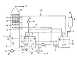
- FIGURE shows an embodiment variant of the system according to the invention.
- the system for purification of flue gas from fossil fuels consists essentially of an absorber 2 , the correspondingly dimensioned connection line to the reaction container, the reaction container 4 , consisting of two chambers 4 . 1 , 4 . 2 , next to which a lime or limestone suspension container 6 is situated, on the same level, above which a lime or limestone silo 8 for lime or limestone meal 16 is disposed, whereby the metering device 9 , a metering screw, meters lime or limestone meal 16 into the limestone suspension container 6 .
- Process water 15 is introduced into the container, and the stirring mechanism 17 ensures uniform, thorough mixing.
- a line that forms the inflow 24 to the hydrocyclone leads from first chamber 4 .
- reaction container 4 1 of reaction container 4 to the hydrocyclone 26 , with which gypsum suspension 27 is precipitated.
- the thin-liquid suspension is pumped back to first chamber 4 . 1 or to lime or limestone suspension container 6 in lines 25 for the upper run of hydrocyclone 26 .
- a hydrocyclone pump 23 is disposed in front of hydrocyclone 26 .
- Lines 13 for the limestone suspension lead from lime or limestone suspension container 6 containing the lime or limestone suspension 33 to second chamber 4 . 2 of reaction container 4 , whereby a circulation pump 7 for limestone suspension is disposed in these lines 13 .
- absorption suspension sump 30 In the lower part of absorber 2 , there is the absorption suspension sump 30 , into which a slanted stirring mechanism 17 projects, and from which pipelines 11 for the absorption suspension lead to reaction container 4 . Above absorption suspension sump 30 , the raw gas 1 is issued into absorber 2 . Above this location, two perforated metal sheets 18 are disposed, between which the first spraying level 19 is situated, whereby two additional spraying levels 19 are disposed above the second perforated metal sheet 18 . Lines for the absorption suspension 12 lead to the lower spraying levels 19 , on which lines a circulation pump 5 is situated, and which lines are connected with second chamber 4 . 2 of reaction container 4 .
- purification levels 32 are disposed, between which the precipitator level 20 for coarse droplets and the precipitator level 31 for fine droplets are situated, above which the absorber hood 34 for pure gas 3 is disposed.
- the purification levels 32 have process water 15 applied to them.
- a blower 21 serves for introduction of the oxidation air 22 into the absorption suspension, from which blower a line leads to the lance 28 that is disposed in first chamber 4 . 1 of reaction container 4 .
- An exhaust vapor blower is disposed above the two reaction chambers 4 . 1 , 4 . 2 , and lime/limestone suspension container 6 , with which the exhaust vapor hood 14 draws off exhaust vapors by means of a blower 10 .
- the raw gas 1 to be purified enters into absorber 2 and changes its flow direction upward after entering, and distributes itself uniformly over the absorber cross-section. Afterwards, it flows through a system of contact installations such as perforated metal sheets 18 and three spraying levels 19 equipped with the spray nozzles. These contact installations have circulating absorption and limestone scrubbing suspension applied to them. Pure gas 3 purified in this manner subsequently passes through the upper part of absorber 2 , droplet precipitator levels 20 , 31 , whereby the entrained droplets are effectively precipitated, and leaves absorber 2 through absorber hood 34 .
- the lower part of absorber 2 with absorption suspension sump 30 , is connected with the two-part reaction container 4 by means of pipeline 11 .
- the two-part division of reaction container 4 takes place by means of a partition wall 29 , which represents an overflow.
- stirring mechanisms 17 are disposed, which serve for suspension and dispersion.
- oxidation air 22 is introduced into first chamber 4 . 1 .
- the task of this oxidation air 22 consists in introducing an amount of air into the suspension that is independent of load, in order to oxidize the calcium sulfite that is formed during the SO 2 precipitation, to form calcium sulfate.
- the amount of compressed air 22 that is required for oxidation is independent of the SO 2 load and is made available by the blower 21 .
- a suspension is drawn off from the first chamber 4 . 1 , and gypsum suspension 27 is precipitated by means of hydrocyclone 26 .
- Second chamber 4 . 2 of reaction container 4 serves as a pump reservoir for the circulation pump 5 of the absorption suspension, which supplies spray levels 19 in absorber 2 that have been described.
- Second chamber 4 . 2 is equipped with a vertically disposed stirring mechanism 17 for suspension.
- first chamber 4 . 1 of reaction chamber 4 into second chamber 4 . 2 ensures quiet feed and degasification of the excess oxidation air 22 from the suspension and from this container part.
- Both container parts 4 . 1 , 4 . 2 are vented by means of an exhaust vapor hood with an integrated droplet precipitator, which is disposed centrally on the container roof.
- the gas that is drawn off which consists predominantly of oxidation air and CO 2 , is purified by the droplet precipitator and passed off separately, by way of the exhaust vapor blower 10 .
- the CO 2 contained in it can be separated in a further method step.
- the invention has the advantage that contaminants of the CO 2 -rich gas (flue gas from the oxyfuel process) are removed and avoided for one thing by efficient precipitation of the concentrated harmful gases and harmful substances from the flue gas, and for another, by avoiding the introduction of air into the harmful gas absorption stage, whereby the oxidation can take place at lower pH values by separation of the oxidation from the limestone metering, and therefore improved process management, improved and more cost-advantageous flue gas purification is achieved.
Landscapes
- Engineering & Computer Science (AREA)
- Chemical & Material Sciences (AREA)
- Health & Medical Sciences (AREA)
- Biomedical Technology (AREA)
- Environmental & Geological Engineering (AREA)
- Analytical Chemistry (AREA)
- General Chemical & Material Sciences (AREA)
- Oil, Petroleum & Natural Gas (AREA)
- Chemical Kinetics & Catalysis (AREA)
- Treating Waste Gases (AREA)
- Gas Separation By Absorption (AREA)
Applications Claiming Priority (4)
| Application Number | Priority Date | Filing Date | Title |
|---|---|---|---|
| DE102007050904 | 2007-10-23 | ||
| DE102007050904A DE102007050904B4 (de) | 2007-10-23 | 2007-10-23 | Anlage und Verfahren zur Reinigung von Rauchgasen |
| DE102007050904.0 | 2007-10-23 | ||
| PCT/DE2008/001605 WO2009052775A1 (de) | 2007-10-23 | 2008-10-06 | Anlage und verfahren zur reinigung von rauchgasen |
Related Parent Applications (1)
| Application Number | Title | Priority Date | Filing Date |
|---|---|---|---|
| PCT/DE2008/001605 Continuation WO2009052775A1 (de) | 2007-10-23 | 2008-10-06 | Anlage und verfahren zur reinigung von rauchgasen |
Publications (2)
| Publication Number | Publication Date |
|---|---|
| US20100221162A1 US20100221162A1 (en) | 2010-09-02 |
| US8337790B2 true US8337790B2 (en) | 2012-12-25 |
Family
ID=40386177
Family Applications (1)
| Application Number | Title | Priority Date | Filing Date |
|---|---|---|---|
| US12/798,580 Expired - Fee Related US8337790B2 (en) | 2007-10-23 | 2010-04-07 | System and method for purification of flue gases |
Country Status (8)
| Country | Link |
|---|---|
| US (1) | US8337790B2 (pl) |
| EP (1) | EP2207611B1 (pl) |
| CN (1) | CN101939080B (pl) |
| DE (1) | DE102007050904B4 (pl) |
| ES (1) | ES2530674T3 (pl) |
| PL (1) | PL2207611T3 (pl) |
| RU (1) | RU2459655C2 (pl) |
| WO (1) | WO2009052775A1 (pl) |
Cited By (4)
| Publication number | Priority date | Publication date | Assignee | Title |
|---|---|---|---|---|
| EP3069781A1 (en) | 2015-03-20 | 2016-09-21 | General Electric Technology GmbH | System for sulphur removal from a flue gas |
| US10016721B1 (en) | 2017-05-25 | 2018-07-10 | Jiangnan Environmental Protection Group Inc. | Ammonia-based desufurization process and apparatus |
| US10207220B2 (en) * | 2017-03-15 | 2019-02-19 | Jiangnan Environmental Protection Group Inc. | Method and apparatus for removing sulfur oxides from gas |
| US10245546B1 (en) | 2018-08-22 | 2019-04-02 | H & H Inventions & Enterprises, Inc. | Exhaust gas purification method and system |
Families Citing this family (16)
| Publication number | Priority date | Publication date | Assignee | Title |
|---|---|---|---|---|
| US8795416B2 (en) * | 2009-10-12 | 2014-08-05 | Babcock & Wilcox Power Generation Group, Inc. | Segregated in-situ forced oxidation wet flue gas desulfurization for oxygen-fired fossil fuel combustion |
| US8173090B2 (en) * | 2010-07-08 | 2012-05-08 | Air Products And Chemicals, Inc. | Sorbent use with oxyfuel sour compression |
| CA2816988A1 (en) * | 2010-11-05 | 2012-05-10 | Fluor Technologies Corporation | Flue gas diffuser objects |
| ES2610619T3 (es) | 2010-11-25 | 2017-04-28 | General Electric Technology Gmbh | Depurador en húmedo para eliminar dióxido de azufre de un gas de proceso |
| US20140314651A1 (en) * | 2013-02-27 | 2014-10-23 | Fuel Tech, Inc. | Process and Apparatus for Improving the Operation of Wet Scrubbers |
| WO2014152760A2 (en) | 2013-03-15 | 2014-09-25 | Oy Halton Group Ltd. | Water spray fume cleansing with demand-based operation |
| CN103657352B (zh) * | 2013-12-16 | 2015-07-29 | 华陆工程科技有限责任公司 | 高纯度硫化氢回收装置及回收方法 |
| EP3124096B1 (de) * | 2015-07-30 | 2019-03-13 | Steinmüller Babcock Environment GmbH | Kalkstein/kalkhydrat-rauchgasreinigungsanlage mit reingas-bypasskanal und sumpferweiterungssystem |
| CN105241998A (zh) * | 2015-09-07 | 2016-01-13 | 内蒙古科技大学 | 一种检测高温热解废气吸收装置吸收效果的试验系统 |
| CN107261992A (zh) * | 2016-04-07 | 2017-10-20 | 叶汉华 | 燃煤电厂烟气二氧化硫〔so2〕催化脱硫生产及工艺流程中的棱形催化塔和催化塔内设施的设计 |
| EP3706882A4 (en) * | 2017-11-08 | 2021-08-18 | BTU International, Inc. | DEVICES, SYSTEMS AND METHODS FOR REMOVING FLUX FROM A FURNACE PROCESS GAS |
| RU2679238C1 (ru) * | 2018-01-30 | 2019-02-06 | Кирилл Николаевич Войнов | Способ улавливания выхлопных газов |
| RU2656458C1 (ru) * | 2018-01-30 | 2018-06-05 | Кирилл Николаевич Войнов | Ловушка вредных испарений и запахов |
| GR1009733B (el) * | 2018-12-27 | 2020-05-15 | Δουσης, Ευαγγελος Γεωργιου | Συστημα αποθειωσης καυσαεριων σε υφισταμενη καπνοδοχο πλοιου |
| CN115920610A (zh) * | 2022-03-16 | 2023-04-07 | 金雪龙 | 一种煅烧co2气体减排吸收工艺 |
| CN115006988A (zh) * | 2022-07-06 | 2022-09-06 | 河南城建学院 | 一种脱硫脱硝除尘装置 |
Citations (27)
| Publication number | Priority date | Publication date | Assignee | Title |
|---|---|---|---|---|
| US2080779A (en) | 1937-05-18 | Purification of combustion gases | ||
| US3961018A (en) * | 1973-12-06 | 1976-06-01 | United Air Specialists, Inc. | Method for purification of gas streams by removal of acidic gases |
| DE2939744A1 (de) | 1979-10-01 | 1981-04-02 | Saarberg-Fernwärme GmbH, 6600 Saarbrücken | Verfahren zum entfernen von schadstoffen aus rauchgasen |
| US4263021A (en) * | 1972-12-05 | 1981-04-21 | The Babcock & Wilcox Company | Gas-liquid contact system |
| DE3136155A1 (de) | 1980-09-12 | 1982-04-01 | Mitsubishi Jukogyo K.K., Tokyo | Verfahren zur zufuehrung von absorbenzien beim nass-kalk-verfahren zur desulfurierung von abgas |
| US4340572A (en) * | 1978-05-19 | 1982-07-20 | Woodside Construction, Inc. | Process for recovering heat from stack or flue gas |
| US4687649A (en) | 1983-09-09 | 1987-08-18 | Babcock-Hitachi Kabushiki Kaisha | Flue gas desulfurization process |
| WO1988007023A1 (en) | 1987-03-13 | 1988-09-22 | Dansk Biologisk Produktion Amba | A method for the catalytic oxidation in aqueous medium of sulphite and/or bisulphite to sulphate |
| DD269893A1 (de) | 1987-12-30 | 1989-07-12 | Orgreb Inst Kraftwerke | Verfahren und anordnung zur additivsuspensionierung fuer die rauchgasentschwefelung |
| EP0339683A2 (en) | 1988-04-29 | 1989-11-02 | Dravo Lime Company | Process for desulphurisation of a sulphur dioxide-containing gas stream |
| DD289211A5 (de) | 1989-11-22 | 1991-04-25 | Th Zittau,De | Verfahren zur internen sulfitoxydation in nassen rauchgasentschwefelungsanlagen |
| US5084255A (en) | 1991-03-26 | 1992-01-28 | Dravco Lime Company | Sulfur dioxide removal process with gypsum and magnesium hydroxide production |
| US5213782A (en) | 1991-11-22 | 1993-05-25 | Electric Power Research Institute | Clear liquor scrubbing magnesium-enhanced lime flue gas desulfurization process |
| US5308509A (en) | 1993-03-08 | 1994-05-03 | The Babcock & Wilcox Company | FGD performance enhancement by hydroclone and recycling steps |
| DE4331415A1 (de) | 1993-09-15 | 1995-03-16 | Steinmueller Gmbh L & C | Verfahren und Vorrichtung zur Behandlung eines Gasstromes mit Waschflüssigkeit |
| US5486342A (en) * | 1994-06-13 | 1996-01-23 | Electric Power Research Institute | Clear liquor scrubbing of sulfur dioxide with forced oxidation in flue gas desulfurization system |
| US5630991A (en) | 1994-08-16 | 1997-05-20 | General Electric Co. | Limestone-based wet flue gas desulfurization process |
| US5635149A (en) * | 1994-06-09 | 1997-06-03 | Abb Environmental Systems Division Of Abb Flakt, Inc. | Wet scrubbing method and apparatus for removing sulfur oxides from combustion effluents |
| US5674459A (en) | 1994-09-08 | 1997-10-07 | The Babcock & Wilcox Company | Hydrogen peroxide for flue gas desulfurization |
| US5779999A (en) * | 1995-12-29 | 1998-07-14 | Marsulex Environmental Technologies, Llc | Method for scrubbing flue gases |
| US5787821A (en) * | 1996-02-13 | 1998-08-04 | The Babcock & Wilcox Company | High velocity integrated flue gas treatment scrubbing system |
| US6007783A (en) * | 1996-10-17 | 1999-12-28 | Mitsubishi Heavy Industries, Ltd. | Flue gas treating system and process |
| US6110256A (en) * | 1998-06-17 | 2000-08-29 | Croll Reynolds Clean Air Technologies, Inc. | Apparatus and method for removing particulates and corrosive gases from a gas stream |
| KR20010077204A (ko) * | 2000-02-01 | 2001-08-17 | 정영근 | 반건조 반응기 |
| DE102004061727A1 (de) | 2003-12-19 | 2005-07-28 | Technische Universität Dresden | Verfahren zur Behandlung der Schwefeldioxid/Schwefeltrioxid-Fracht im CO2-Stromes aus einem CO2-freien Kraftwerk |
| US20050271569A1 (en) * | 2002-09-24 | 2005-12-08 | Kvaerner Power Oy | Method and an apparatus for processing flue gas scrubber material flows |
| US7722843B1 (en) * | 2006-11-24 | 2010-05-25 | Srivats Srinivasachar | System and method for sequestration and separation of mercury in combustion exhaust gas aqueous scrubber systems |
Family Cites Families (5)
| Publication number | Priority date | Publication date | Assignee | Title |
|---|---|---|---|---|
| JPS5210838B2 (pl) * | 1971-11-11 | 1977-03-26 | ||
| NL9500215A (nl) * | 1995-02-06 | 1996-09-02 | Biostar Bv | Werkwijze voor het zuiveren van stikstofoxiden bevattend rookgas. |
| CN1087645C (zh) * | 1996-01-11 | 2002-07-17 | 彭斯干 | 烟气循环流化法脱硫工艺方法及装置 |
| CN1213580A (zh) * | 1997-10-05 | 1999-04-14 | 陈然振 | 副产石膏的烟气脱硫技术及装置 |
| CN1141168C (zh) * | 1998-04-01 | 2004-03-10 | 富兰克林·S·查默斯 | 处理由烟道气脱硫或其它来源产生的含硫物质的方法 |
-
2007
- 2007-10-23 DE DE102007050904A patent/DE102007050904B4/de not_active Expired - Fee Related
-
2008
- 2008-10-06 WO PCT/DE2008/001605 patent/WO2009052775A1/de not_active Ceased
- 2008-10-06 EP EP08842569.9A patent/EP2207611B1/de not_active Not-in-force
- 2008-10-06 ES ES08842569T patent/ES2530674T3/es active Active
- 2008-10-06 CN CN200880113003.9A patent/CN101939080B/zh not_active Expired - Fee Related
- 2008-10-06 RU RU2010120568/05A patent/RU2459655C2/ru active
- 2008-10-06 PL PL08842569T patent/PL2207611T3/pl unknown
-
2010
- 2010-04-07 US US12/798,580 patent/US8337790B2/en not_active Expired - Fee Related
Patent Citations (27)
| Publication number | Priority date | Publication date | Assignee | Title |
|---|---|---|---|---|
| US2080779A (en) | 1937-05-18 | Purification of combustion gases | ||
| US4263021A (en) * | 1972-12-05 | 1981-04-21 | The Babcock & Wilcox Company | Gas-liquid contact system |
| US3961018A (en) * | 1973-12-06 | 1976-06-01 | United Air Specialists, Inc. | Method for purification of gas streams by removal of acidic gases |
| US4340572A (en) * | 1978-05-19 | 1982-07-20 | Woodside Construction, Inc. | Process for recovering heat from stack or flue gas |
| DE2939744A1 (de) | 1979-10-01 | 1981-04-02 | Saarberg-Fernwärme GmbH, 6600 Saarbrücken | Verfahren zum entfernen von schadstoffen aus rauchgasen |
| DE3136155A1 (de) | 1980-09-12 | 1982-04-01 | Mitsubishi Jukogyo K.K., Tokyo | Verfahren zur zufuehrung von absorbenzien beim nass-kalk-verfahren zur desulfurierung von abgas |
| US4687649A (en) | 1983-09-09 | 1987-08-18 | Babcock-Hitachi Kabushiki Kaisha | Flue gas desulfurization process |
| WO1988007023A1 (en) | 1987-03-13 | 1988-09-22 | Dansk Biologisk Produktion Amba | A method for the catalytic oxidation in aqueous medium of sulphite and/or bisulphite to sulphate |
| DD269893A1 (de) | 1987-12-30 | 1989-07-12 | Orgreb Inst Kraftwerke | Verfahren und anordnung zur additivsuspensionierung fuer die rauchgasentschwefelung |
| EP0339683A2 (en) | 1988-04-29 | 1989-11-02 | Dravo Lime Company | Process for desulphurisation of a sulphur dioxide-containing gas stream |
| DD289211A5 (de) | 1989-11-22 | 1991-04-25 | Th Zittau,De | Verfahren zur internen sulfitoxydation in nassen rauchgasentschwefelungsanlagen |
| US5084255A (en) | 1991-03-26 | 1992-01-28 | Dravco Lime Company | Sulfur dioxide removal process with gypsum and magnesium hydroxide production |
| US5213782A (en) | 1991-11-22 | 1993-05-25 | Electric Power Research Institute | Clear liquor scrubbing magnesium-enhanced lime flue gas desulfurization process |
| US5308509A (en) | 1993-03-08 | 1994-05-03 | The Babcock & Wilcox Company | FGD performance enhancement by hydroclone and recycling steps |
| DE4331415A1 (de) | 1993-09-15 | 1995-03-16 | Steinmueller Gmbh L & C | Verfahren und Vorrichtung zur Behandlung eines Gasstromes mit Waschflüssigkeit |
| US5635149A (en) * | 1994-06-09 | 1997-06-03 | Abb Environmental Systems Division Of Abb Flakt, Inc. | Wet scrubbing method and apparatus for removing sulfur oxides from combustion effluents |
| US5486342A (en) * | 1994-06-13 | 1996-01-23 | Electric Power Research Institute | Clear liquor scrubbing of sulfur dioxide with forced oxidation in flue gas desulfurization system |
| US5630991A (en) | 1994-08-16 | 1997-05-20 | General Electric Co. | Limestone-based wet flue gas desulfurization process |
| US5674459A (en) | 1994-09-08 | 1997-10-07 | The Babcock & Wilcox Company | Hydrogen peroxide for flue gas desulfurization |
| US5779999A (en) * | 1995-12-29 | 1998-07-14 | Marsulex Environmental Technologies, Llc | Method for scrubbing flue gases |
| US5787821A (en) * | 1996-02-13 | 1998-08-04 | The Babcock & Wilcox Company | High velocity integrated flue gas treatment scrubbing system |
| US6007783A (en) * | 1996-10-17 | 1999-12-28 | Mitsubishi Heavy Industries, Ltd. | Flue gas treating system and process |
| US6110256A (en) * | 1998-06-17 | 2000-08-29 | Croll Reynolds Clean Air Technologies, Inc. | Apparatus and method for removing particulates and corrosive gases from a gas stream |
| KR20010077204A (ko) * | 2000-02-01 | 2001-08-17 | 정영근 | 반건조 반응기 |
| US20050271569A1 (en) * | 2002-09-24 | 2005-12-08 | Kvaerner Power Oy | Method and an apparatus for processing flue gas scrubber material flows |
| DE102004061727A1 (de) | 2003-12-19 | 2005-07-28 | Technische Universität Dresden | Verfahren zur Behandlung der Schwefeldioxid/Schwefeltrioxid-Fracht im CO2-Stromes aus einem CO2-freien Kraftwerk |
| US7722843B1 (en) * | 2006-11-24 | 2010-05-25 | Srivats Srinivasachar | System and method for sequestration and separation of mercury in combustion exhaust gas aqueous scrubber systems |
Non-Patent Citations (1)
| Title |
|---|
| International Search Report of PCT/DE2008/001605. |
Cited By (11)
| Publication number | Priority date | Publication date | Assignee | Title |
|---|---|---|---|---|
| EP3069781A1 (en) | 2015-03-20 | 2016-09-21 | General Electric Technology GmbH | System for sulphur removal from a flue gas |
| WO2016150801A1 (en) * | 2015-03-20 | 2016-09-29 | Alstom Technology Ltd | System for sulphur removal from a flue gas |
| US10040024B2 (en) | 2015-03-20 | 2018-08-07 | General Electric Technology Gmbh | System for sulphur removal from a flue gas |
| US10207220B2 (en) * | 2017-03-15 | 2019-02-19 | Jiangnan Environmental Protection Group Inc. | Method and apparatus for removing sulfur oxides from gas |
| US10016721B1 (en) | 2017-05-25 | 2018-07-10 | Jiangnan Environmental Protection Group Inc. | Ammonia-based desufurization process and apparatus |
| US10399033B2 (en) | 2017-05-25 | 2019-09-03 | Jiangnan Environmental Protection Group Inc. | Ammonia-based desulfurization process and apparatus |
| US10406478B2 (en) | 2017-05-25 | 2019-09-10 | Jiangnan Environmental Protection Group Inc. | Ammonia-based desulfurization process and apparatus |
| US10413865B2 (en) | 2017-05-25 | 2019-09-17 | Jiangnan Enviromental Protection Group Inc. | Ammonia-based desulfurization process and apparatus |
| US10561982B2 (en) | 2017-05-25 | 2020-02-18 | Jiangnan Environmental Protection Group Inc. | Ammonia-based desulfurization process and apparatus |
| US10245546B1 (en) | 2018-08-22 | 2019-04-02 | H & H Inventions & Enterprises, Inc. | Exhaust gas purification method and system |
| US10905993B2 (en) | 2018-08-22 | 2021-02-02 | H & H Inventions & Enterprises, Inc. | Exhaust gas purification method and system |
Also Published As
| Publication number | Publication date |
|---|---|
| EP2207611B1 (de) | 2014-12-10 |
| CN101939080A (zh) | 2011-01-05 |
| ES2530674T3 (es) | 2015-03-04 |
| RU2459655C2 (ru) | 2012-08-27 |
| US20100221162A1 (en) | 2010-09-02 |
| WO2009052775A1 (de) | 2009-04-30 |
| DE102007050904B4 (de) | 2013-07-25 |
| DE102007050904A1 (de) | 2009-05-07 |
| RU2010120568A (ru) | 2011-11-27 |
| CN101939080B (zh) | 2014-08-06 |
| PL2207611T3 (pl) | 2015-06-30 |
| EP2207611A1 (de) | 2010-07-21 |
Similar Documents
| Publication | Publication Date | Title |
|---|---|---|
| US20100221162A1 (en) | System and method for purification of flue gases | |
| KR100382444B1 (ko) | 연도기체세정장치 | |
| US5674459A (en) | Hydrogen peroxide for flue gas desulfurization | |
| RU2645987C2 (ru) | Способ и устройство для удаления примесей из выхлопных газов | |
| US6277343B1 (en) | Flue gas scrubbing method and apparatus therefor | |
| CN86106161A (zh) | 同时进行氧化硫吸收和生产硫酸铵的方法和设备 | |
| RU2149679C1 (ru) | Способ мокрой очистки и устройство для удаления оксидов серы из продуктов сгорания | |
| US6187278B1 (en) | Process for controlling ammonia slip in the reduction of sulfur dioxide emission | |
| US6254771B1 (en) | Method of processing desulfurization absorption liquid and apparatus therefor | |
| CN101306319A (zh) | 直排式烟气处理方法 | |
| US20030175193A1 (en) | FGD gypsum dewatering improvement through crystal habit modification by carboxylic acids | |
| KR100518049B1 (ko) | 연도 가스 세정 방법 | |
| EP2851345B1 (en) | Method and apparatus for catalyzing the oxidation of sulphite to sulphate in seawater aeration basins | |
| CN205461680U (zh) | 一种脱硫除尘装置 | |
| CN101279190A (zh) | 采用鼓泡段的直排式烟气处理方法及其设备 | |
| US20060210453A1 (en) | Flue gas purification device | |
| JPH11147022A (ja) | 排煙脱硫方法 |
Legal Events
| Date | Code | Title | Description |
|---|---|---|---|
| AS | Assignment |
Owner name: BABCOCK NOELL GMBH, GERMANY Free format text: ASSIGNMENT OF ASSIGNORS INTEREST;ASSIGNORS:WELP, HELMUT;SCHMIDT, THOMAS;REEL/FRAME:024236/0225 Effective date: 20100406 |
|
| STCF | Information on status: patent grant |
Free format text: PATENTED CASE |
|
| FPAY | Fee payment |
Year of fee payment: 4 |
|
| MAFP | Maintenance fee payment |
Free format text: PAYMENT OF MAINTENANCE FEE, 8TH YEAR, LARGE ENTITY (ORIGINAL EVENT CODE: M1552); ENTITY STATUS OF PATENT OWNER: LARGE ENTITY Year of fee payment: 8 |
|
| FEPP | Fee payment procedure |
Free format text: MAINTENANCE FEE REMINDER MAILED (ORIGINAL EVENT CODE: REM.); ENTITY STATUS OF PATENT OWNER: LARGE ENTITY |
|
| LAPS | Lapse for failure to pay maintenance fees |
Free format text: PATENT EXPIRED FOR FAILURE TO PAY MAINTENANCE FEES (ORIGINAL EVENT CODE: EXP.); ENTITY STATUS OF PATENT OWNER: LARGE ENTITY |
|
| STCH | Information on status: patent discontinuation |
Free format text: PATENT EXPIRED DUE TO NONPAYMENT OF MAINTENANCE FEES UNDER 37 CFR 1.362 |
|
| FP | Lapsed due to failure to pay maintenance fee |
Effective date: 20241225 |