US8422915B2 - Developer cartridge, developing device, and image forming apparatus having the same - Google Patents
Developer cartridge, developing device, and image forming apparatus having the same Download PDFInfo
- Publication number
- US8422915B2 US8422915B2 US12/240,716 US24071608A US8422915B2 US 8422915 B2 US8422915 B2 US 8422915B2 US 24071608 A US24071608 A US 24071608A US 8422915 B2 US8422915 B2 US 8422915B2
- Authority
- US
- United States
- Prior art keywords
- developer
- cartridge
- shutter
- transfer
- developing
- Prior art date
- Legal status (The legal status is an assumption and is not a legal conclusion. Google has not performed a legal analysis and makes no representation as to the accuracy of the status listed.)
- Expired - Fee Related, expires
Links
Images




Classifications
-
- G—PHYSICS
- G03—PHOTOGRAPHY; CINEMATOGRAPHY; ANALOGOUS TECHNIQUES USING WAVES OTHER THAN OPTICAL WAVES; ELECTROGRAPHY; HOLOGRAPHY
- G03G—ELECTROGRAPHY; ELECTROPHOTOGRAPHY; MAGNETOGRAPHY
- G03G15/00—Apparatus for electrographic processes using a charge pattern
- G03G15/06—Apparatus for electrographic processes using a charge pattern for developing
- G03G15/08—Apparatus for electrographic processes using a charge pattern for developing using a solid developer, e.g. powder developer
-
- G—PHYSICS
- G03—PHOTOGRAPHY; CINEMATOGRAPHY; ANALOGOUS TECHNIQUES USING WAVES OTHER THAN OPTICAL WAVES; ELECTROGRAPHY; HOLOGRAPHY
- G03G—ELECTROGRAPHY; ELECTROPHOTOGRAPHY; MAGNETOGRAPHY
- G03G15/00—Apparatus for electrographic processes using a charge pattern
- G03G15/06—Apparatus for electrographic processes using a charge pattern for developing
- G03G15/08—Apparatus for electrographic processes using a charge pattern for developing using a solid developer, e.g. powder developer
- G03G15/0822—Arrangements for preparing, mixing, supplying or dispensing developer
- G03G15/0844—Arrangements for purging used developer from the developing unit
-
- G—PHYSICS
- G03—PHOTOGRAPHY; CINEMATOGRAPHY; ANALOGOUS TECHNIQUES USING WAVES OTHER THAN OPTICAL WAVES; ELECTROGRAPHY; HOLOGRAPHY
- G03G—ELECTROGRAPHY; ELECTROPHOTOGRAPHY; MAGNETOGRAPHY
- G03G15/00—Apparatus for electrographic processes using a charge pattern
- G03G15/06—Apparatus for electrographic processes using a charge pattern for developing
- G03G15/08—Apparatus for electrographic processes using a charge pattern for developing using a solid developer, e.g. powder developer
- G03G15/0822—Arrangements for preparing, mixing, supplying or dispensing developer
- G03G15/0848—Arrangements for testing or measuring developer properties or quality, e.g. charge, size, flowability
- G03G15/0849—Detection or control means for the developer concentration
- G03G15/0855—Detection or control means for the developer concentration the concentration being measured by optical means
-
- G—PHYSICS
- G03—PHOTOGRAPHY; CINEMATOGRAPHY; ANALOGOUS TECHNIQUES USING WAVES OTHER THAN OPTICAL WAVES; ELECTROGRAPHY; HOLOGRAPHY
- G03G—ELECTROGRAPHY; ELECTROPHOTOGRAPHY; MAGNETOGRAPHY
- G03G15/00—Apparatus for electrographic processes using a charge pattern
- G03G15/06—Apparatus for electrographic processes using a charge pattern for developing
- G03G15/08—Apparatus for electrographic processes using a charge pattern for developing using a solid developer, e.g. powder developer
- G03G15/0822—Arrangements for preparing, mixing, supplying or dispensing developer
- G03G15/0865—Arrangements for supplying new developer
-
- G—PHYSICS
- G03—PHOTOGRAPHY; CINEMATOGRAPHY; ANALOGOUS TECHNIQUES USING WAVES OTHER THAN OPTICAL WAVES; ELECTROGRAPHY; HOLOGRAPHY
- G03G—ELECTROGRAPHY; ELECTROPHOTOGRAPHY; MAGNETOGRAPHY
- G03G15/00—Apparatus for electrographic processes using a charge pattern
- G03G15/06—Apparatus for electrographic processes using a charge pattern for developing
- G03G15/08—Apparatus for electrographic processes using a charge pattern for developing using a solid developer, e.g. powder developer
- G03G15/0822—Arrangements for preparing, mixing, supplying or dispensing developer
- G03G15/0865—Arrangements for supplying new developer
- G03G15/0875—Arrangements for supplying new developer cartridges having a box like shape
-
- G—PHYSICS
- G03—PHOTOGRAPHY; CINEMATOGRAPHY; ANALOGOUS TECHNIQUES USING WAVES OTHER THAN OPTICAL WAVES; ELECTROGRAPHY; HOLOGRAPHY
- G03G—ELECTROGRAPHY; ELECTROPHOTOGRAPHY; MAGNETOGRAPHY
- G03G15/00—Apparatus for electrographic processes using a charge pattern
- G03G15/06—Apparatus for electrographic processes using a charge pattern for developing
- G03G15/08—Apparatus for electrographic processes using a charge pattern for developing using a solid developer, e.g. powder developer
- G03G15/0822—Arrangements for preparing, mixing, supplying or dispensing developer
- G03G15/0877—Arrangements for metering and dispensing developer from a developer cartridge into the development unit
-
- G—PHYSICS
- G03—PHOTOGRAPHY; CINEMATOGRAPHY; ANALOGOUS TECHNIQUES USING WAVES OTHER THAN OPTICAL WAVES; ELECTROGRAPHY; HOLOGRAPHY
- G03G—ELECTROGRAPHY; ELECTROPHOTOGRAPHY; MAGNETOGRAPHY
- G03G15/00—Apparatus for electrographic processes using a charge pattern
- G03G15/06—Apparatus for electrographic processes using a charge pattern for developing
- G03G15/08—Apparatus for electrographic processes using a charge pattern for developing using a solid developer, e.g. powder developer
- G03G15/0822—Arrangements for preparing, mixing, supplying or dispensing developer
- G03G15/0877—Arrangements for metering and dispensing developer from a developer cartridge into the development unit
- G03G15/0881—Sealing of developer cartridges
- G03G15/0886—Sealing of developer cartridges by mechanical means, e.g. shutter, plug
-
- G—PHYSICS
- G03—PHOTOGRAPHY; CINEMATOGRAPHY; ANALOGOUS TECHNIQUES USING WAVES OTHER THAN OPTICAL WAVES; ELECTROGRAPHY; HOLOGRAPHY
- G03G—ELECTROGRAPHY; ELECTROPHOTOGRAPHY; MAGNETOGRAPHY
- G03G21/00—Arrangements not provided for by groups G03G13/00 - G03G19/00, e.g. cleaning, elimination of residual charge
- G03G21/10—Collecting or recycling waste developer
-
- G—PHYSICS
- G03—PHOTOGRAPHY; CINEMATOGRAPHY; ANALOGOUS TECHNIQUES USING WAVES OTHER THAN OPTICAL WAVES; ELECTROGRAPHY; HOLOGRAPHY
- G03G—ELECTROGRAPHY; ELECTROPHOTOGRAPHY; MAGNETOGRAPHY
- G03G21/00—Arrangements not provided for by groups G03G13/00 - G03G19/00, e.g. cleaning, elimination of residual charge
- G03G21/10—Collecting or recycling waste developer
- G03G21/12—Toner waste containers
-
- G—PHYSICS
- G03—PHOTOGRAPHY; CINEMATOGRAPHY; ANALOGOUS TECHNIQUES USING WAVES OTHER THAN OPTICAL WAVES; ELECTROGRAPHY; HOLOGRAPHY
- G03G—ELECTROGRAPHY; ELECTROPHOTOGRAPHY; MAGNETOGRAPHY
- G03G2215/00—Apparatus for electrophotographic processes
- G03G2215/06—Developing structures, details
- G03G2215/066—Toner cartridge or other attachable and detachable container for supplying developer material to replace the used material
- G03G2215/0692—Toner cartridge or other attachable and detachable container for supplying developer material to replace the used material using a slidable sealing member, e.g. shutter
Definitions
- the present invention relates to an image forming apparatus, and more particularly, to a developing device in an image forming apparatus having the same.
- An forming apparatus such as, for example, a printer, a photocopier, a facsimile machine, a multifunction peripheral, or the like, performs printing of images using developer. After repeated printing operations, the developer may be used up, and thus may need to be replenished.
- a developing cartridge containing storing the developer therein may need to be replaced.
- the developing cartridge may also include other components, such as, e.g., a developing roller and/or a supply roller, which may have relatively longer useful life. Replacement of the developing cartridge for the purpose of developer replenishment may thus be uneconomical.
- the present applicants have contemporaneously herewith suggested a separable type developing cartridge with a removable developer cartridge that allows the developer to be replenished with replacement of only the removable developer cartridge.
- the removable developer cartridge may alleviate the need for unnecessary replacement of the entire developing cartridge, the replacement of the removable developer cartridge may become messy as remaining developer often leaks out of the opening through which the developer is supplied outside the removable cartridge, and may result in contaminating other components of the image forming apparatus.
- FIG. 1 is a perspective view schematically illustrating an image forming apparatus according to an embodiment of the present invention
- FIG. 2 is a cross-section view schematically illustrating a developing device of FIG. 1 ;
- FIG. 3 is a perspective view schematically illustrating a collecting path formed in a developing device according to an embodiment of the invention
- FIG. 4 is a perspective view schematically illustrating a developer cartridge to be mounted in a developing cartridge according to an embodiment of the invention
- FIG. 5A through 5C are views illustrating opening operations of a first shutter member and a second shutter member according to an embodiment of the invention
- FIGS. 6A through 6C are views illustrating closing operations of the first and the second shutter members according to an embodiment of the invention.
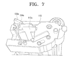
- FIG. 7 is a perspective view illustrating a locking protrusion of the developing cartridge according to an embodiment of the invention.
- FIGS. 8A and 8B are perspective views illustrating operations of a fourth shutter member according to an embodiment of the invention.
- FIGS. 9 and 10 are perspective views illustrating operations of a third shutter member according to an embodiment of the invention.
- FIGS. 11 and 12 are perspective views schematically illustrating a developing device according to an embodiment of the present invention.
- an image forming apparatus 1 may include an image forming apparatus body 10 and a developing device 100 .
- the image forming apparatus body 10 has a transfer path formed therein to transfer a printing medium using transferring means such as rollers and has various of parts housed therein for forming an image on the transferred printing medium.
- the developing device 100 enters the image forming apparatus body 10 in the direction R 2 (See FIG. 4 ), and may be mounted in the image forming apparatus body 10 .
- the developing device 100 may include a developing cartridge 110 , a developer containing unit 120 , and shutter units 130 as shown in FIG. 2 .
- the developing cartridge 110 may be employed to develop an electrostatic latent image formed on a photoconductive medium 20 with developer, and may include a developing roller 111 to develop the electrostatic latent image of the photoconductive medium 20 and a supply roller 112 to supply developer to the developing roller 111 . Also, the developing cartridge 110 may further include first and second agitating rollers 113 and 114 to agitate the developer in the developing cartridge 110 and to uniformly transfer the developer to the supply roller 112 .
- the photoconductive medium 20 may be mounted in the developing cartridge 110 , and also, a cleaning blade 21 for cleaning a remaining developer off the photoconductive medium 20 may be supported in the developing cartridge 110 .
- the photoconductive medium 20 and/or the cleaning blade 21 may be disposed in the image forming apparatus separately from the developing device 100 .
- the developer containing unit 120 may contain a quantity of developer therein, and, as shown in FIG. 4 , is removably mounted in the developing cartridge 110 .
- the developing cartridge 110 has a mounting recess 110 a (see FIG. 4 ) for accommodating the developer containing unit 120 .
- the mounting recess 110 a may be formed to extend along the length of, and from one end to the other end of, the developing cartridge 110 , penetrating through the developing cartridge 110 , and may have a predetermined depth. and a predetermined length parallel to the direction R 1 perpendicular to the mounting direction R 2 (see FIG. 4 ) of the developing cartridge 110 . Accordingly, the developer containing unit 120 enters the developing cartridge 110 in the direction of R 1 perpendicular to the mounting direction R 2 of the developing cartridge 110 .
- the developer containing unit 120 if the developer containing unit 120 is mounted in the developing cartridge 110 , the developer containing unit 120 forms a developer transfer paths T 1 and T 2 in association with the developing cartridge 110 .
- the developer containing unit 120 is a developer cartridge 121 that supplies the developer to the developing cartridge 110 , and may also collect waste developer discharged from the developing cartridge 110 .
- the developer transfer paths T 1 and T 2 formed between the developer cartridge 121 and the developing cartridge 110 are, respectively, a supply path T 1 , through which the developer is supplied from the developer cartridge 121 to the developing cartridge 110 , and a collecting path T 2 , through which waste developer discharged from the developing cartridge 110 is collected in the developer cartridge 121 .
- the supply path T 1 includes first and second transfer openings 122 and 116 , which are formed in the developer cartridge 121 and in the developing cartridge 110 , respectively, such that they face each other, and fluidly communicate with each other if the developer cartridge 121 is mounted in the developing cartridge 110 .
- the first transfer opening 122 serves as an outlet through which the developer is discharged from the developer cartridge 121
- the second transfer opening 116 serves as an inlet through which the developer flows into the developing cartridge 110 .
- the developer cartridge 121 may have a developer transfer member 124 rotatably formed therein to transfer the developer from the developer cartridge 121 to the supply path T 1 through the first transfer opening 122 .
- the collecting path T 2 may include third and fourth transfer openings 117 and 123 , which are formed in the developing cartridge 110 and in the developer cartridge 121 , respectively, such that they face, and fluidly communicate with, each other if the developer cartridge 121 is mounted in the developing cartridge 110 .
- the third transfer opening 117 serves as the waste developer outlet, through which the waste developer is discharged from the developing cartridge 110
- the fourth transfer opening 123 serves as the waste developer inlet, through which the waste developer flows into the developer cartridge 121 .
- the waste developer is developer that has been cleaned off the photoconductive medium 20 by the cleaning blade 21 , and, as shown in FIGS. 2 and 3 , is transferred to the collecting path T 2 by waste developer transferring mechanism 22 .
- the waste developer transferring mechanism 22 may include a waste developer transfer member 23 and a waste developer transfer pipe 24 .
- the supply path T 1 and the collecting path T 2 are formed in the proximity of the entering or leading end and an exiting or trailing end of the developer cartridge 121 , respectively, with reference to the mounting direction of the developer cartridge 121 .
- the shutter units 130 opens the developer transfer paths T 1 and T 2 only if the developer cartridge 121 is mounted in the developing cartridge 110 . That is, the shutter units 130 opens both the supply path T 1 and the collecting path T 2 if the developer cartridge 121 is mounted in the developing cartridge 110 , and conversely, closes both of them if the developer cartridge 121 is removed from the developing cartridge 110 .
- the shutter unit 130 includes first through fourth shutter members 131 , 132 , 133 , 134 corresponding to the first through fourth transfer openings 122 , 116 , 117 , 123 .
- the first and the second shutter members 131 , 132 are disposed in the developer cartridge 121 and the developing cartridge 110 , respectively, to open and close the first and the second transfer openings 122 and 116 , respectively.
- the third and the fourth shutter members 133 and 134 are disposed in the developing cartridge 110 and the developer cartridge 121 , respectively, to open and close the third and the fourth transfer openings 117 and 123 , respectively.
- the first, the second, and the fourth shutter members 131 , 132 , 134 open the first, the second, and the fourth transfer openings 122 , 116 , 123 if the developer cartridge 121 is mounted in the mounting recess 110 a of the developing cartridge 110 in the first direction R 1 .
- the third shutter member 133 opens the third transfer opening 116 if the developing cartridge 110 is mounted in the image forming apparatus body 10 in the second direction R 2 .
- the first through fourth shutter members 131 , 132 , 133 , 134 described above are elastically supported by first through fourth elastic members 135 , 136 , 137 , 138 , respectively, in directions of closing the first through the fourth transfer openings 122 , 116 , 117 , 123 .
- the first shutter member 131 is prevented from moving further in the direction R 1 by the locking projection 131 b formed in the proximity of the second transfer opening 116 of the developing cartridge 110 , thereby opening the first transfer opening 122 . That is, although the developer cartridge 121 moves in the first direction R 1 , the first shutter member 131 is interfered by the locking projection 131 b , and does not move in the first direction R 1 such that the first transfer opening 122 of the developer cartridge 121 is opened.
- the end of the first shutter member 131 which is brought into contact with the locking projection 131 b , is bent toward the developing cartridge 110 while the other end is supported by the first elastic member 135 .
- the guide lever 140 On the locking projection 131 b is disposed a guide lever 140 which is rotated by the interference from the developer cartridge 121 , and which assists the first shutter member 131 in opening and closing the first transfer opening 122 .
- the guide lever 140 includes first and second wings 141 and 142 rotating about a rotary shaft 140 a and a pressure protrusion 143 .
- the first wing 141 is rotated by the bent end of the first shutter member 131 in the first direction R 1 , and, as shown in FIG. 5C , has a length such that the first wing 141 is brought into contact with the bottom 121 c of the developer cartridge 121 facing the developing cartridge 110 .
- the second wing 142 may have a shorter length than that of the first wing 141 , and may be spaced from the first wing 141 at a predetermined angle. Therefore, the second wing 142 is not brought into contact with the bottom 121 c of the developer cartridge 121 when rotated to the position shown in FIG. 5C .
- the pressure protrusion 143 protrudes from the second wing 142 and presses the one end of the first shutter member 131 in the first direction R 1 if the first wing 141 is brought into contact with the bottom of the developer cartridge 121 .
- the second shutter member 132 is interfered by a leading end 121 a of the developer cartridge 121 with reference to the first direction R 1 , and thus moves in the first direction R 1 , thereby opening the second transfer opening 116 .
- the leading end 121 a which enters the mounting recess 110 a first with reference to the mounting direction of the developer cartridge 121 i.e. the direction R 1 , is brought into contact with the second shutter member 132 of the developing cartridge 110 , and the other end of the developer cartridge 121 is exposed to the outside through the mounting recess 110 a , and forms an outer wall together with the developing cartridge 110 as shown in FIG. 3 .
- the second shutter member 132 has an inclined surface 132 a to restore the guide lever 140 to the initial position. More specifically, as shown in FIG. 6C , if the leading end 121 a of the developer cartridge 121 moves in the direction R 3 opposite to the mounting direction R 1 , and thus the first wing 141 is released from the contact with the bottom of the developer cartridge 121 , the inclined surface 132 a of the second shutter member 132 , which is free from the contact force with the leading end 121 a of the developer cartridge 121 , is brought into contact with the first wing 141 , and thus, the first wing 141 is rotated in the direction R 3 opposite to the mounting direction R 1 , and is restored to the original position by a recovering force of the second shutter member 132 . For this, the inclined surface 132 a of the second shutter member 132 is inclined by a predetermined angle corresponding to the initial position of the first wing 141 .
- the third shutter member 133 opens the third transfer opening 116 as an interference member 133 a protruding from the third shutter member 133 is interfered by the image forming apparatus body 10 , and thus moves in the first direction R 1 . More specifically, if the developing cartridge 110 enters in the second direction R 2 and is mounted in the image forming apparatus body 10 with the developer cartridge 121 mounted therein, the interference member 133 a protruding from the developing cartridge 110 is brought into contact with the image forming apparatus body 10 and thus moves in the direction R 1 such that the third shutter member 122 opens the third transfer opening 116 .
- the fourth shutter member 134 moves in the direction R 3 opposite to the mounting direction R 1 by means of a locking protrusion 134 a formed on the developing cartridge 110 , thereby opening the fourth opening 123 .
- the bent end 131 a of the first shutter member 131 is brought into contact with the locking projection 131 b and thus is prevented from entering further in the first direction R 1 .
- the bent end 131 a of the first shutter member 131 is also brought into contact with the first wing 141 of the guide lever 140 and thus rotates the first wing 141 in the first direction R 1 as shown in FIGS. 5A and 5B .
- the developer cartridge 121 continues to enter in the first direction R 1 and thus moves the second shutter member 132 which is in contact with the leading end 121 a of the developer cartridge 121 in the first direction R 1 .
- the first and the second transfer openings 122 are 116 are opened by the first and the second shutter members 131 and 132 such that the supply path T 1 for transferring the developer from the developer cartridge 121 to the developing cartridge 110 is open.
- the first wing 141 which has rotated in contact with one end of the first shutter member 131 in the first direction R 1 , is in contact with the bottom of the developer cartridge 121 and is prevented from rotating in the first direction R 1 as shown in FIG. 5C . Accordingly, the one end of the first shutter member 131 is released from the contact with the first wing 141 , and, instead, is brought into contact with the pressure protrusion 143 protruding from the second wing 142 spaced from the first wing 141 by a predetermined angle.
- the bent end 131 a of the first shutter member 131 is fixedly at the location between the locking projection 131 b and the pressure protrusion 143 such that the first shutter member 131 is fixed at the position of opening the first transfer opening 122 .
- the fourth shutter member 134 is brought into contact with the locking protrusion 134 a formed on the developing cartridge 110 , and thus moves in the direction R 3 opposite the mounting direction R 1 , thereby opening the fourth transfer opening 123 .
- the first, the second, and the fourth transfer openings 122 , 116 and 123 are all open by the first, the second and the fourth shutter members 131 , 132 and 134 , respectively.
- the developing cartridge 110 enters the image forming apparatus body 10 in the second direction R 2 with the developer cartridge 121 mounted therein.
- the interference member 133 a protruding from the third shutter member 133 to protrude from the developing cartridge 110 is brought into contact with the image forming apparatus body 10 , thereby moving the third shutter member 133 in the first direction R 1 .
- the third transfer opening 116 becomes open by the third shutter member 133 such that the developer supply path T 1 and the collecting path T 2 between the developer cartridge 121 and the developing cartridge 110 are all open.
- the first and the second shutter members 131 and 132 open the first and the second transfer openings 122 and 116 in sequence in association with the mounting operation of the developer cartridge 121 , and then, the fourth transfer opening 123 of the developer cartridge 121 is opened by the fourth shutter member 134 .
- the third transfer opening 117 is opened by the third shutter member 133 such that the developer collecting path T 2 is finally opened. That is, the shutter units 130 opens the developer supply path T 1 first, and then opens the developer collecting path T 2 .
- the developing cartridge 110 is dismounted from the image forming apparatus body 10 in a direction R 4 opposite to the second direction R 2 , at which time, the interference member 133 a is released from the interference force from the image forming apparatus body 10 such that the interference member 133 a is restored to an initial position by an elastic force of the third elastic member 137 . Accordingly, the third shutter member 133 closes the third transfer opening 116 in association with the movement of the interference member 133 a.
- the developer cartridge 121 may be removed in the direction R 3 opposite to the mounting direction R 1 .
- the first, the second, and the fourth shutter members 131 , 132 and 134 being free from the mounting force between the developer cartridge 121 and the developing cartridge 110 , are released from the contacts with respect to the locking projection 131 b , the leading end 121 a of the developer cartridge 121 , and the locking protrusion 134 a , respectively. Accordingly, the first, the second, and the fourth shutter members 131 , 132 and 134 are restored into their respective initial positions by elastic bias from the first, the second and the fourth elastic members 135 , 136 and 138 .
- a recovering force of the second elastic member 136 for restoring the second shutter member 132 is exerted in the direction R 3 opposite to the mounting direction R 1 of the developer cartridge 121 , assisting in the dismounting the developer cartridge 121 from the developing cartridge 110 .
- the pressure protrusion 143 of the guide lever 140 presses and supports the bent end of the first shutter member 131 in the first direction R 1 until the first wing 141 is released from the contact with the bottom of the developing cartridge 121 . Consequently, the pulling by the guide lever 140 of first shutter member 131 in the first direction R 1 , in addition to the recovering force of the first elastic member 135 toward the first direction R 1 , acts to completely close the first transfer opening 122 .
- the contact force between the pressure protrusion 143 and the first shutter member 131 is maintained until the first wing 141 becomes free from the contact force with respect to the bottom 121 c of the developer cartridge 121 , and is rotated by the inclined surface 132 a of the second shutter member 132 in the opposite direction of the mounting direction R 1 to release the bent end 131 a of the first shutter member 131 from the pressure protrusion 143 .
- the inclined surface 132 a of the second shutter member 132 interferes with, and further rotates, the first wing 141 in the direction R 3 , thereby restoring the guide lever 140 to the initial position.
- the third transfer opening 117 of the developing cartridge 110 is first closed by the third shutter member 133 .
- the fourth transfer opening 123 is closed by the fourth shutter member 134 and then the first and the second transfer openings 122 and 116 are closed by the first and the second shutter members 131 and 132 . That is, as the developer cartridge 121 is dismounted, the developer collecting path T 2 is closed first and then the developer supply path T 1 is closed.
- FIGS. 11 and 12 illustrate an image forming apparatus according to another embodiment of the present invention.
- a developing device 200 of an image forming apparatus 1 is similar to the developing device 100 of the image forming apparatus of previously described embodiment in that it includes a developing cartridge, a developer containing unit 120 , and a shutter 130 .
- the elements similar to those of the previously embodiment are assigned with the same reference numerals, and were previously described with reference to FIGS. 1 through 10 .
- the developing device 200 includes a waste developer container 221 , which does not contain developer for supplying to the developing cartridge 110 , but has a structure for collecting waste developer discharged from the developing cartridge 110 .
- the waste developer container 221 includes only a collecting path T 2 as the developer transfer path.
- the developing device 200 may have a quantity of developer in the developing cartridge sufficient for printing a number of printing medium.
- a developer cartridge 121 as illustrated in the previous embodiments e.g., may be mounted in the mounting recess 110 a of the developing cartridge 110 , replacing the waste developer container 221 .
- the shutter unit 130 includes third and fourth shutter members 133 and 134 disposed in the developing cartridge 110 and the waste developer container 221 , respectively, to open and close the third and the fourth transfer openings 117 and 123 .
- the third and the fourth shutter members 133 and 134 opens the third and the fourth transfer openings 117 and 123 , respectively as the developing cartridge 110 is mounted in the image forming apparatus body 10 and the waste developer container 221 is mounted in the developing cartridge 10 .
- the third and the fourth shutter members 133 and 134 are elastically supported by third and fourth elastic members 137 and 138 in directions of closing the third and the fourth transfer openings 117 and 123 .
- the third and the fourth shutter members 133 and 134 are interfered by the image forming apparatus body 10 and by a locking protrusion 134 a formed on the developing cartridge 110 , respectively, and thus are made to move in the direction R 1 , thereby opening the third and the fourth transfer openings 117 and 123 .
- Operations of opening and closing the collecting path T 2 of the developing device 200 of the image forming apparatus 1 according to the embodiment shown in FIGS. 11 and 12 are similar to the operations of opening and closing the collecting path T 2 of the developing device 100 according to the embodiment described earlier, and thus detailed descriptions thereof will not be repeated.
- the image forming apparatus can be used economically.
- the transfer path for the developer is selectively opened and closed in association with operations of mounting and dismounting the developer cartridge 121 containing the developer and/or the waste developer container 221 in and from the developing cartridge 110 , a developer leak may be reduced during the replacement. Therefore, contaminations due to developer leak may be prevented.
Landscapes
- Physics & Mathematics (AREA)
- General Physics & Mathematics (AREA)
- Life Sciences & Earth Sciences (AREA)
- Engineering & Computer Science (AREA)
- Environmental & Geological Engineering (AREA)
- Sustainable Development (AREA)
- Dry Development In Electrophotography (AREA)
- Electrophotography Configuration And Component (AREA)
- Cleaning In Electrography (AREA)
Applications Claiming Priority (2)
| Application Number | Priority Date | Filing Date | Title |
|---|---|---|---|
| KR1020080016469A KR100912900B1 (ko) | 2008-02-22 | 2008-02-22 | 현상제카트리지, 현상장치 및 이를 포함하는 화상형성장치 |
| KR10-2008-0016469 | 2008-02-22 |
Publications (2)
| Publication Number | Publication Date |
|---|---|
| US20090214269A1 US20090214269A1 (en) | 2009-08-27 |
| US8422915B2 true US8422915B2 (en) | 2013-04-16 |
Family
ID=40626837
Family Applications (1)
| Application Number | Title | Priority Date | Filing Date |
|---|---|---|---|
| US12/240,716 Expired - Fee Related US8422915B2 (en) | 2008-02-22 | 2008-09-29 | Developer cartridge, developing device, and image forming apparatus having the same |
Country Status (7)
| Country | Link |
|---|---|
| US (1) | US8422915B2 (de) |
| EP (1) | EP2093626B1 (de) |
| KR (1) | KR100912900B1 (de) |
| CN (1) | CN101515135B (de) |
| BR (1) | BRPI0805399B1 (de) |
| ES (1) | ES2642048T3 (de) |
| RU (1) | RU2411564C2 (de) |
Cited By (1)
| Publication number | Priority date | Publication date | Assignee | Title |
|---|---|---|---|---|
| US11467516B2 (en) | 2012-06-03 | 2022-10-11 | Ricoh Company, Ltd. | Powder container and image forming apparatus |
Families Citing this family (15)
| Publication number | Priority date | Publication date | Assignee | Title |
|---|---|---|---|---|
| JP5531579B2 (ja) * | 2008-11-27 | 2014-06-25 | 株式会社リコー | 粉体補給装置、画像形成装置及び粉体容器 |
| JP5056929B2 (ja) * | 2010-09-27 | 2012-10-24 | 富士ゼロックス株式会社 | 粉体収容容器、画像形成装置 |
| JP5696935B2 (ja) * | 2011-02-21 | 2015-04-08 | 株式会社リコー | 粉体補給装置及び画像形成装置 |
| KR101532204B1 (ko) * | 2011-01-24 | 2015-06-29 | 삼성전자 주식회사 | 화상형성장치 |
| KR20140135347A (ko) * | 2013-05-16 | 2014-11-26 | 삼성전자주식회사 | 현상장치 및 이를 갖는 화상형성장치 |
| KR102048753B1 (ko) * | 2013-10-25 | 2019-11-27 | 휴렛-팩커드 디벨롭먼트 컴퍼니, 엘.피. | 화상 형성장치 및 화상 형성장치의 메인티넌스 방법 |
| KR20150098421A (ko) | 2014-02-20 | 2015-08-28 | 삼성전자주식회사 | 카트리지 유닛 및 이를 구비하는 전자사진방식 화상형성장치 |
| US9851657B2 (en) | 2014-08-22 | 2017-12-26 | Sharp Kabushiki Kaisha | Image forming apparatus |
| AU2015383280B2 (en) * | 2015-02-17 | 2018-01-18 | Kyocera Document Solutions Inc. | Developer container and image formation device equipped with same |
| JP7051347B2 (ja) | 2017-09-21 | 2022-04-11 | キヤノン株式会社 | 現像剤補給容器及び現像剤補給システム |
| JP7005249B2 (ja) * | 2017-09-21 | 2022-01-21 | キヤノン株式会社 | 現像剤補給容器及び現像剤補給システム |
| JP7119502B2 (ja) | 2018-03-30 | 2022-08-17 | ブラザー工業株式会社 | 現像カートリッジ |
| JP7484306B2 (ja) * | 2020-03-26 | 2024-05-16 | 富士フイルムビジネスイノベーション株式会社 | 回収容器及び粉体塗装装置 |
| CN111562731A (zh) * | 2020-06-09 | 2020-08-21 | 江西凯利德科技有限公司 | 显影剂供应装置 |
| US12140883B2 (en) | 2023-03-03 | 2024-11-12 | Lexmark International, Inc. | Toner container having a toner port shutter interface |
Citations (46)
| Publication number | Priority date | Publication date | Assignee | Title |
|---|---|---|---|---|
| JPS60238873A (ja) | 1984-05-11 | 1985-11-27 | Fuji Xerox Co Ltd | トナ−補給装置 |
| JPS6491164A (en) | 1987-10-02 | 1989-04-10 | Ricoh Kk | Developing device |
| US4967234A (en) | 1987-11-10 | 1990-10-30 | Ricoh Company, Ltd. | Image forming apparatus |
| US4974020A (en) | 1986-09-30 | 1990-11-27 | Mita Industrial Co. | Removable developing units for a copying machine and display for indicating the useful life of the machine |
| US4977429A (en) | 1988-11-08 | 1990-12-11 | Ricoh Company, Ltd. | Apparatus for supplying toner to an image forming apparatus |
| KR910001489A (ko) | 1989-06-01 | 1991-01-31 | 야마모또 다꾸마 | 전기식 사진 촬영 분야에 사용되는 현상 장치 |
| EP0672971A2 (de) | 1994-03-15 | 1995-09-20 | Canon Kabushiki Kaisha | Elektrophotographisches Bilderzeugungsgerät |
| US5479247A (en) | 1992-06-30 | 1995-12-26 | Fujitsu Limited | Developer cartridge and image forming apparatus using the same |
| US5493366A (en) | 1990-09-07 | 1996-02-20 | Konica Corporation | Image forming apparatus |
| US5499077A (en) | 1994-05-17 | 1996-03-12 | Brother Kogyo Kabushiki Kaisha | Toner level detecting device |
| JPH0922177A (ja) | 1995-07-04 | 1997-01-21 | Canon Inc | トナーカートリッジ、プロセスカートリッジ、トナーホッパー及び画像形成装置 |
| US5649264A (en) | 1993-11-18 | 1997-07-15 | Canon Kabushiki Kaisha | Developing unit having optical detection of a residual quantity of developer in a developer container |
| US5734953A (en) | 1995-02-17 | 1998-03-31 | Ricoh Company, Ltd. | Detachable toner supply and processing assembly for an image forming apparatus and having a shutter mechanism for toner flow control |
| JPH10142910A (ja) | 1996-11-08 | 1998-05-29 | Katsuragawa Electric Co Ltd | トナー供給方式 |
| US5848342A (en) | 1994-03-03 | 1998-12-08 | Kyocera Corporation | Residual toner collecting unit |
| JPH1124513A (ja) | 1997-06-27 | 1999-01-29 | Canon Inc | トナー補給装置及び電子写真画像形成装置 |
| US5960238A (en) | 1997-04-25 | 1999-09-28 | Nec Corporation | Method of supplying toner for process cartridge and process cartridge for image forming apparatus |
| JP2000075627A (ja) | 1998-09-02 | 2000-03-14 | Fuji Xerox Co Ltd | 現像装置 |
| JP2000075659A (ja) | 1998-08-31 | 2000-03-14 | Canon Inc | カラー電子写真画像形成装置及び現像カートリッジ |
| US6041212A (en) * | 1997-11-06 | 2000-03-21 | Mita Industrial Co., Ltd. | Toner replenishing device of image forming machine and toner cartridge for use therein |
| US6104888A (en) | 1997-11-12 | 2000-08-15 | Minolta Co., Ltd. | System for determining a characteristic of an image forming unit detachably mounted in an image forming apparatus |
| EP1103865A2 (de) | 1999-11-29 | 2001-05-30 | Canon Kabushiki Kaisha | Entwicklerzuführbehälter, Entwicklervorratsbehälter, Arbeitseinheit und Bilderzeugungsgerät |
| US20020085857A1 (en) | 2000-12-29 | 2002-07-04 | Kyung-Hwan Kim | Developing unit-toner cartridge assembly of image forming apparatus |
| US20020085887A1 (en) | 2000-09-01 | 2002-07-04 | Walter Aktiengesellschaft (Ag) | Metal cutting tool with direct cutting plate arrangement |
| US20020141788A1 (en) * | 2001-03-30 | 2002-10-03 | Canon Kabushiki Kaisha | Image forming apparatus and developer supplying container detachably attachable thereto |
| US20030161653A1 (en) | 1997-06-19 | 2003-08-28 | Canon Kabushiki Kaisha | Toner supply container and electrophotographic image forming apparatus |
| US20040001723A1 (en) | 2002-06-28 | 2004-01-01 | Minolta Company, Ltd. | Image forming apparatus and toner cartridge therefor |
| EP1437632A1 (de) | 1997-09-30 | 2004-07-14 | Canon Kabushiki Kaisha | Tonerbehälter, Tonerzuführssystem, Entwicklerbehälter und diesen verwendendes Bilderzeugungsgerät |
| US6792230B2 (en) | 2001-12-20 | 2004-09-14 | Fuji Xerox Co., Ltd | Image forming apparatus and process cartridge and developing unit for the image forming apparatus with efficient toner replenishing |
| JP2004264539A (ja) | 2003-02-28 | 2004-09-24 | Toshiba Tec Corp | トナーカートリッジ及び画像形成装置 |
| US20040223772A1 (en) | 2003-03-20 | 2004-11-11 | Seiko Epson Corporation | Image forming apparatus and a storage controlling method for information on an improper detachment of developer cartridge to be written in a cartridge storage means |
| US20050047821A1 (en) | 2003-08-29 | 2005-03-03 | Canon Kabushiki Kaisha | Process cartridge, mounting mechanism therefor and electrophotographic image forming apparatus |
| KR20050033796A (ko) | 2003-10-08 | 2005-04-13 | 캐논 가부시끼가이샤 | 프로세스 카트리지 및 전자사진 화상 형성 장치 |
| US20050095020A1 (en) | 2003-10-31 | 2005-05-05 | Eom Yoon-Seop | Apparatus for managing consumables of image forming apparatus |
| US20050254860A1 (en) | 2004-05-14 | 2005-11-17 | Fuji Xerox Co., Ltd. | Developer recovering mechanism and image forming apparatus |
| JP2005338329A (ja) | 2004-05-26 | 2005-12-08 | Fuji Xerox Co Ltd | プロセスカートリッジ及び画像形成装置 |
| RU2266553C2 (ru) | 2002-11-08 | 2005-12-20 | Кэнон Кабусики Кайся | Устройство формирования изображения, картридж, система формирования изображения и запоминающая среда для картриджа |
| JP2006091284A (ja) | 2004-09-22 | 2006-04-06 | Fuji Xerox Co Ltd | プロセスカートリッジ及びこれを有する画像形成装置 |
| KR20060034168A (ko) | 2004-10-18 | 2006-04-21 | 삼성전자주식회사 | 화상형성기기의 상형성장치 |
| JP2006309016A (ja) | 2005-04-28 | 2006-11-09 | Ricoh Co Ltd | 現像装置、プロセスカートリッジ及び画像形成装置 |
| KR20060128338A (ko) | 2005-06-10 | 2006-12-14 | 삼성전자주식회사 | 현상기 및 이를 채용한 칼라화상형성장치 |
| US20060285880A1 (en) | 2001-09-13 | 2006-12-21 | Brother Kogyo Kabushiki Kaisha | Image forming device and detachably loaded process unit |
| JP2007025511A (ja) | 2005-07-21 | 2007-02-01 | Oki Data Corp | 現像剤カートリッジ、現像装置、及び画像形成装置 |
| US20070071503A1 (en) * | 2005-09-21 | 2007-03-29 | Brother Kogyo Kabushiki Kaisha | Image forming device, developing device and toner cartridge |
| EP1840671A1 (de) | 2006-03-31 | 2007-10-03 | Oki Data Corporation | Tonerkartusche mit Speicherelement, Bildtrommeleinheit und Bilderzeugungsvorrichtung |
| US20080056772A1 (en) | 2006-08-29 | 2008-03-06 | Fuji Xerox Co., Ltd. | Developer transport apparatus and image forming apparatus |
Family Cites Families (4)
| Publication number | Priority date | Publication date | Assignee | Title |
|---|---|---|---|---|
| KR920010230B1 (ko) * | 1987-11-10 | 1992-11-21 | 가부시기가이샤 리코 | 화상형성장치 |
| JP3366295B2 (ja) * | 1998-10-12 | 2003-01-14 | コピア株式会社 | 画像形成装置 |
| EP1898274B1 (de) * | 2002-09-24 | 2011-04-20 | Ricoh Company, Ltd. | Bilderzeugungsvorrichtung mit einem Bildträgerelement und einem Schutzverschluss |
| KR100756044B1 (ko) * | 2005-08-29 | 2007-09-07 | 삼성전자주식회사 | 현상제통과 현상제 공급장치 및 이를 가지는 화상형성장치 |
-
2008
- 2008-02-22 KR KR1020080016469A patent/KR100912900B1/ko not_active Expired - Fee Related
- 2008-09-29 US US12/240,716 patent/US8422915B2/en not_active Expired - Fee Related
- 2008-11-11 CN CN2008101740154A patent/CN101515135B/zh not_active Expired - Fee Related
- 2008-12-09 RU RU2008148633/28A patent/RU2411564C2/ru active
- 2008-12-10 BR BRPI0805399-5A patent/BRPI0805399B1/pt not_active IP Right Cessation
-
2009
- 2009-02-11 ES ES09152577.4T patent/ES2642048T3/es active Active
- 2009-02-11 EP EP09152577.4A patent/EP2093626B1/de not_active Not-in-force
Patent Citations (58)
| Publication number | Priority date | Publication date | Assignee | Title |
|---|---|---|---|---|
| JPS60238873A (ja) | 1984-05-11 | 1985-11-27 | Fuji Xerox Co Ltd | トナ−補給装置 |
| EP0570993A1 (de) | 1986-09-30 | 1993-11-24 | Mita Industrial Co., Ltd. | Bilderzeugungsgerät |
| US4974020A (en) | 1986-09-30 | 1990-11-27 | Mita Industrial Co. | Removable developing units for a copying machine and display for indicating the useful life of the machine |
| JPS6491164A (en) | 1987-10-02 | 1989-04-10 | Ricoh Kk | Developing device |
| US4967234A (en) | 1987-11-10 | 1990-10-30 | Ricoh Company, Ltd. | Image forming apparatus |
| US4977429A (en) | 1988-11-08 | 1990-12-11 | Ricoh Company, Ltd. | Apparatus for supplying toner to an image forming apparatus |
| KR910001489A (ko) | 1989-06-01 | 1991-01-31 | 야마모또 다꾸마 | 전기식 사진 촬영 분야에 사용되는 현상 장치 |
| US5493366A (en) | 1990-09-07 | 1996-02-20 | Konica Corporation | Image forming apparatus |
| US5479247A (en) | 1992-06-30 | 1995-12-26 | Fujitsu Limited | Developer cartridge and image forming apparatus using the same |
| US5649264A (en) | 1993-11-18 | 1997-07-15 | Canon Kabushiki Kaisha | Developing unit having optical detection of a residual quantity of developer in a developer container |
| US5848342A (en) | 1994-03-03 | 1998-12-08 | Kyocera Corporation | Residual toner collecting unit |
| EP0672971A2 (de) | 1994-03-15 | 1995-09-20 | Canon Kabushiki Kaisha | Elektrophotographisches Bilderzeugungsgerät |
| US5589915A (en) | 1994-03-15 | 1996-12-31 | Canon Kabushiki Kaisha | Electrophotographic image forming apparatus with toner box exchange alarm feature |
| US5499077A (en) | 1994-05-17 | 1996-03-12 | Brother Kogyo Kabushiki Kaisha | Toner level detecting device |
| US5734953A (en) | 1995-02-17 | 1998-03-31 | Ricoh Company, Ltd. | Detachable toner supply and processing assembly for an image forming apparatus and having a shutter mechanism for toner flow control |
| JPH0922177A (ja) | 1995-07-04 | 1997-01-21 | Canon Inc | トナーカートリッジ、プロセスカートリッジ、トナーホッパー及び画像形成装置 |
| JPH10142910A (ja) | 1996-11-08 | 1998-05-29 | Katsuragawa Electric Co Ltd | トナー供給方式 |
| US5960238A (en) | 1997-04-25 | 1999-09-28 | Nec Corporation | Method of supplying toner for process cartridge and process cartridge for image forming apparatus |
| US20030161653A1 (en) | 1997-06-19 | 2003-08-28 | Canon Kabushiki Kaisha | Toner supply container and electrophotographic image forming apparatus |
| JPH1124513A (ja) | 1997-06-27 | 1999-01-29 | Canon Inc | トナー補給装置及び電子写真画像形成装置 |
| EP1437632A1 (de) | 1997-09-30 | 2004-07-14 | Canon Kabushiki Kaisha | Tonerbehälter, Tonerzuführssystem, Entwicklerbehälter und diesen verwendendes Bilderzeugungsgerät |
| US6041212A (en) * | 1997-11-06 | 2000-03-21 | Mita Industrial Co., Ltd. | Toner replenishing device of image forming machine and toner cartridge for use therein |
| US6104888A (en) | 1997-11-12 | 2000-08-15 | Minolta Co., Ltd. | System for determining a characteristic of an image forming unit detachably mounted in an image forming apparatus |
| US6151459A (en) | 1998-08-31 | 2000-11-21 | Canon Kabushiki Kaisha | Development cartridge and image forming apparatus |
| JP2000075659A (ja) | 1998-08-31 | 2000-03-14 | Canon Inc | カラー電子写真画像形成装置及び現像カートリッジ |
| JP2000075627A (ja) | 1998-09-02 | 2000-03-14 | Fuji Xerox Co Ltd | 現像装置 |
| EP1103865A2 (de) | 1999-11-29 | 2001-05-30 | Canon Kabushiki Kaisha | Entwicklerzuführbehälter, Entwicklervorratsbehälter, Arbeitseinheit und Bilderzeugungsgerät |
| CN1298126A (zh) | 1999-11-29 | 2001-06-06 | 佳能株式会社 | 显影剂供应盒,显影剂接收盒,操作盒和成象装置 |
| KR20010061976A (ko) | 1999-11-29 | 2001-07-07 | 미다라이 후지오 | 현상제 공급 카트리지, 현상제 수용 카트리지, 프로세스카트리지 및 화상 형성 장치 |
| US20020085887A1 (en) | 2000-09-01 | 2002-07-04 | Walter Aktiengesellschaft (Ag) | Metal cutting tool with direct cutting plate arrangement |
| US20020085857A1 (en) | 2000-12-29 | 2002-07-04 | Kyung-Hwan Kim | Developing unit-toner cartridge assembly of image forming apparatus |
| US20020141788A1 (en) * | 2001-03-30 | 2002-10-03 | Canon Kabushiki Kaisha | Image forming apparatus and developer supplying container detachably attachable thereto |
| US20060285880A1 (en) | 2001-09-13 | 2006-12-21 | Brother Kogyo Kabushiki Kaisha | Image forming device and detachably loaded process unit |
| US6792230B2 (en) | 2001-12-20 | 2004-09-14 | Fuji Xerox Co., Ltd | Image forming apparatus and process cartridge and developing unit for the image forming apparatus with efficient toner replenishing |
| US20040001723A1 (en) | 2002-06-28 | 2004-01-01 | Minolta Company, Ltd. | Image forming apparatus and toner cartridge therefor |
| RU2266553C2 (ru) | 2002-11-08 | 2005-12-20 | Кэнон Кабусики Кайся | Устройство формирования изображения, картридж, система формирования изображения и запоминающая среда для картриджа |
| JP2004264539A (ja) | 2003-02-28 | 2004-09-24 | Toshiba Tec Corp | トナーカートリッジ及び画像形成装置 |
| US20040223772A1 (en) | 2003-03-20 | 2004-11-11 | Seiko Epson Corporation | Image forming apparatus and a storage controlling method for information on an improper detachment of developer cartridge to be written in a cartridge storage means |
| US20060210285A1 (en) | 2003-03-20 | 2006-09-21 | Seiko Epson Corporation | Image forming apparatus and a storage controlling method for information on an improper detachment of a developer cartridge to be written in a cartridge storage means |
| US20050047821A1 (en) | 2003-08-29 | 2005-03-03 | Canon Kabushiki Kaisha | Process cartridge, mounting mechanism therefor and electrophotographic image forming apparatus |
| US7340197B2 (en) | 2003-08-29 | 2008-03-04 | Canon Kabushiki Kaisha | Process cartridge, mounting mechanism therefor and electrophotographic image forming apparatus |
| US20050260011A1 (en) | 2003-08-29 | 2005-11-24 | Canon Kabushiki Kaisha | Process cartridge, mounting mechanism therefor and electrophotographic image forming apparatus |
| US6980758B2 (en) | 2003-08-29 | 2005-12-27 | Canon Kabushiki Kaisha | Process cartridge, mounting mechanism therefor and electrophotographic image forming apparatus |
| KR20050033796A (ko) | 2003-10-08 | 2005-04-13 | 캐논 가부시끼가이샤 | 프로세스 카트리지 및 전자사진 화상 형성 장치 |
| EP1881378A1 (de) | 2003-10-08 | 2008-01-23 | Canon Kabushiki Kaisha | Prozesskartusche und Elektrophotographisches Bilderzeugungsgerät |
| US20050095020A1 (en) | 2003-10-31 | 2005-05-05 | Eom Yoon-Seop | Apparatus for managing consumables of image forming apparatus |
| US20050254860A1 (en) | 2004-05-14 | 2005-11-17 | Fuji Xerox Co., Ltd. | Developer recovering mechanism and image forming apparatus |
| JP2005326637A (ja) | 2004-05-14 | 2005-11-24 | Fuji Xerox Co Ltd | 現像剤回収機構及び画像形成装置 |
| JP2005338329A (ja) | 2004-05-26 | 2005-12-08 | Fuji Xerox Co Ltd | プロセスカートリッジ及び画像形成装置 |
| JP2006091284A (ja) | 2004-09-22 | 2006-04-06 | Fuji Xerox Co Ltd | プロセスカートリッジ及びこれを有する画像形成装置 |
| KR20060034168A (ko) | 2004-10-18 | 2006-04-21 | 삼성전자주식회사 | 화상형성기기의 상형성장치 |
| JP2006309016A (ja) | 2005-04-28 | 2006-11-09 | Ricoh Co Ltd | 現像装置、プロセスカートリッジ及び画像形成装置 |
| KR20060128338A (ko) | 2005-06-10 | 2006-12-14 | 삼성전자주식회사 | 현상기 및 이를 채용한 칼라화상형성장치 |
| JP2007025511A (ja) | 2005-07-21 | 2007-02-01 | Oki Data Corp | 現像剤カートリッジ、現像装置、及び画像形成装置 |
| US20070071503A1 (en) * | 2005-09-21 | 2007-03-29 | Brother Kogyo Kabushiki Kaisha | Image forming device, developing device and toner cartridge |
| EP1840671A1 (de) | 2006-03-31 | 2007-10-03 | Oki Data Corporation | Tonerkartusche mit Speicherelement, Bildtrommeleinheit und Bilderzeugungsvorrichtung |
| US20070230999A1 (en) | 2006-03-31 | 2007-10-04 | Oki Data Corportation | Toner Cartridge, Image Drum Unit and Image Forming Apparatus |
| US20080056772A1 (en) | 2006-08-29 | 2008-03-06 | Fuji Xerox Co., Ltd. | Developer transport apparatus and image forming apparatus |
Non-Patent Citations (48)
| Title |
|---|
| Chinese Office Action issued Apr. 5, 2012 in CN Application No. 200810174015.4. |
| CN Office Action issued Mar. 24, 2011 in CN Application No. 200810174015.4. |
| English abstract of KR 10-2006-0128338, published Dec. 14, 2006. |
| English language abstract of JP 01-091164, published Apr. 10, 1989. |
| English language abstract of JP 09-022177, published Jan. 21, 1997. |
| English language abstract of JP 2000-075659, published Mar. 14, 2000. |
| English language abstract of JP 2004-264539, published Sep. 24, 2004. |
| English language abstract of JP 2005-326637, mailed Nov. 24, 2005. |
| English language abstract of JP 2005-338329, published Dec. 8, 2005. |
| English language abstract of JP 2007-025511, published Feb. 1, 2007. |
| English language abstract of JP 60-238873, published Nov. 27, 1985. |
| English language abstract of KR 10-2001-0061976, published Jul. 7, 2001. |
| English language abstract of KR 10-2005-0033796, published Apr. 13, 2005. |
| English language abstract of KR 10-2006-0034168, published Apr. 21, 2006. |
| English Language abstract of KR 91-1489, published Jan. 31, 1991. |
| English language abstract of RU 2,266,553, published Apr. 20, 2005. |
| English language abstract of RU 2289835, published Dec. 20, 2006. |
| English language translation of Office Action issued in Russian patent application No. 2008148636, mailed Oct. 28, 2009. |
| English language translation of Office Action issued in Russian patent application No. 2008148667, mailed Dec. 11, 2009. |
| European Examination Report issued Apr. 23, 2012 in EP Application No. 09 152 557.4. |
| European Search Report issued Apr. 10, 2012 in EP Application No. 09152577.4. |
| European Search Report issued in EP 09 15 0144, issued Jan. 22, 2010. |
| European Search Report issued in EP 09150067.8, mailed Jun. 3, 2009. |
| European Search Report Issued in European Application No. 09 15 0066, mailed Jul. 29, 2009. |
| European Search Report issued in European Application No. 09 15 0141, mailed Apr. 14, 2009. |
| European Search Report Issued in European Application No. 09 15 2590, mailed Aug. 17, 2009. |
| Korean Office Action issued in Application No. 10-2008-0016455, issued Jan. 23, 2009. |
| Korean Office Action issued in Application No. 10-2008-0016464, mailed Feb. 6, 2009. |
| Korean Office Action issued in Application No. 10-2008-0016467, mailed Jan. 30, 2009. |
| Korean Office Action issued in Application No. 10-2008-0016469, mailed Feb. 6, 2009. |
| Korean Office Action issued in Application No. 10-2008-0016472, mailed Feb. 5, 2009. |
| Machine English language translation of JP 09-022177, published Jan. 21, 1997. |
| Machine English language translation of JP 10-142910, published May 29, 1998. |
| Machine English language translation of JP 11-24513, published Jan. 29, 1999. |
| Machine English language translation of JP 2000-075659, published Mar. 14, 2000. |
| Machine English language translation of JP 2000-75627, published Mar. 14, 2000. |
| Machine English language translation of JP 2004-264539, published Sep. 24, 2004. |
| Machine English language translation of JP 2005-326637, mailed Nov. 24, 2005. |
| Machine English language translation of JP 2005-338329, published Dec. 8, 2005. |
| Machine English language translation of JP 2007-025511, published Feb. 1, 2007. |
| Machine translation of JP 2006-309016. * |
| Notice of Allowance issued in Russian Application No. 2008148634, mailed Jan. 21, 2010. |
| Office Action issued in KR 10-32008-0016469, mailed Jun. 3, 2009. |
| Office Action issued in Russian patent application No. 2008148636, mailed Oct. 28, 2009. |
| Office Action issued in Russian patent application No. 2008148667, mailed Dec. 11, 2009. |
| Partial English language translation of Notice of Allowance issued in Russian Application No. 2008148634, mailed Jan. 21, 2010. |
| Russian Notice of Allowance issued Jul. 22, 2010 in RU Application No. 2008148622. |
| Russian Office Action dated May 4, 2010 issued in RU Application No. 2008148633. |
Cited By (1)
| Publication number | Priority date | Publication date | Assignee | Title |
|---|---|---|---|---|
| US11467516B2 (en) | 2012-06-03 | 2022-10-11 | Ricoh Company, Ltd. | Powder container and image forming apparatus |
Also Published As
| Publication number | Publication date |
|---|---|
| RU2411564C2 (ru) | 2011-02-10 |
| US20090214269A1 (en) | 2009-08-27 |
| BRPI0805399A2 (pt) | 2009-10-06 |
| RU2008148633A (ru) | 2010-06-20 |
| ES2642048T3 (es) | 2017-11-15 |
| BRPI0805399B1 (pt) | 2019-10-01 |
| EP2093626B1 (de) | 2017-08-09 |
| KR100912900B1 (ko) | 2009-08-20 |
| CN101515135A (zh) | 2009-08-26 |
| EP2093626A3 (de) | 2012-05-09 |
| CN101515135B (zh) | 2013-08-21 |
| EP2093626A2 (de) | 2009-08-26 |
Similar Documents
| Publication | Publication Date | Title |
|---|---|---|
| US8422915B2 (en) | Developer cartridge, developing device, and image forming apparatus having the same | |
| KR100362390B1 (ko) | 화상형성장치의 현상기-토너 카트리지 조립체 | |
| US8208836B2 (en) | Developer holding apparatus, developing apparatus, and image forming apparatus | |
| JP2001222160A (ja) | 現像剤補給カートリッジ、現像剤受入カートリッジ、プロセスカートリッジ及び画像形成装置 | |
| EP2237112B1 (de) | Entwicklerspeicherkörper, Bilderzeugungseinheit und Bilderzeugungsvorrichtung | |
| US7389067B2 (en) | Developer cartridge of an image forming apparatus for removably mounting | |
| US11656575B2 (en) | Image forming device | |
| JP2014232270A (ja) | 現像剤収容器、プロセスカートリッジ及び画像形成装置 | |
| KR20120121341A (ko) | 프로세스 카트리지 및 화상 형성 장치 | |
| JP6859824B2 (ja) | 画像形成装置 | |
| JP7131179B2 (ja) | 画像形成装置 | |
| JP2011118040A (ja) | 画像形成ユニット及び画像形成装置 | |
| US6934492B2 (en) | Toner supply container, image formation unit and image forming apparatus | |
| JP2017009931A (ja) | 画像形成装置 | |
| WO2014017358A1 (ja) | 画像形成装置 | |
| US8958719B2 (en) | Image forming apparatus having replaceable modules | |
| JPH10149078A (ja) | 電子写真装置 | |
| JPH1195638A (ja) | 作像ユニット | |
| JP2011215406A (ja) | 画像形成装置 | |
| JP2012242770A (ja) | 現像装置及びそれを備えた画像形成装置 | |
| KR100846834B1 (ko) | 토너 카트리지 | |
| KR100385047B1 (ko) | 레이저 프린터의 토너 카트리지 및 폐토너 회수시스템 | |
| JP2002072817A (ja) | 画像形成装置用ユニット、収納容器、画像形成装置用ユニットと収納容器のアセンブリ、および画像形成装置 | |
| US9213307B2 (en) | Drum cartridge with movable cleaning roller | |
| JP7501251B2 (ja) | 画像形成装置 |
Legal Events
| Date | Code | Title | Description |
|---|---|---|---|
| AS | Assignment |
Owner name: SAMSUNG ELECTRONICS CO., LTD., KOREA, REPUBLIC OF Free format text: ASSIGNMENT OF ASSIGNORS INTEREST;ASSIGNORS:CHOI, SAM-SEOK;LEE, SEUNG-GWEON;EUN, JONG-MOON;AND OTHERS;REEL/FRAME:021602/0168 Effective date: 20080923 |
|
| FEPP | Fee payment procedure |
Free format text: PAYOR NUMBER ASSIGNED (ORIGINAL EVENT CODE: ASPN); ENTITY STATUS OF PATENT OWNER: LARGE ENTITY |
|
| STCF | Information on status: patent grant |
Free format text: PATENTED CASE |
|
| FPAY | Fee payment |
Year of fee payment: 4 |
|
| AS | Assignment |
Owner name: S-PRINTING SOLUTION CO., LTD., KOREA, REPUBLIC OF Free format text: ASSIGNMENT OF ASSIGNORS INTEREST;ASSIGNOR:SAMSUNG ELECTRONICS CO., LTD;REEL/FRAME:041852/0125 Effective date: 20161104 |
|
| AS | Assignment |
Owner name: HP PRINTING KOREA CO., LTD., KOREA, REPUBLIC OF Free format text: CHANGE OF NAME;ASSIGNOR:S-PRINTING SOLUTION CO., LTD.;REEL/FRAME:047370/0405 Effective date: 20180316 |
|
| AS | Assignment |
Owner name: HP PRINTING KOREA CO., LTD., KOREA, REPUBLIC OF Free format text: CORRECTIVE ASSIGNMENT TO CORRECT THE DOCUMENTATION EVIDENCING THE CHANGE OF NAME PREVIOUSLY RECORDED ON REEL 047370 FRAME 0405. ASSIGNOR(S) HEREBY CONFIRMS THE CHANGE OF NAME;ASSIGNOR:S-PRINTING SOLUTION CO., LTD.;REEL/FRAME:047769/0001 Effective date: 20180316 |
|
| AS | Assignment |
Owner name: HP PRINTING KOREA CO., LTD., KOREA, REPUBLIC OF Free format text: CHANGE OF LEGAL ENTITY EFFECTIVE AUG. 31, 2018;ASSIGNOR:HP PRINTING KOREA CO., LTD.;REEL/FRAME:050938/0139 Effective date: 20190611 |
|
| AS | Assignment |
Owner name: HEWLETT-PACKARD DEVELOPMENT COMPANY, L.P., TEXAS Free format text: CONFIRMATORY ASSIGNMENT EFFECTIVE NOVEMBER 1, 2018;ASSIGNOR:HP PRINTING KOREA CO., LTD.;REEL/FRAME:050747/0080 Effective date: 20190826 |
|
| MAFP | Maintenance fee payment |
Free format text: PAYMENT OF MAINTENANCE FEE, 8TH YEAR, LARGE ENTITY (ORIGINAL EVENT CODE: M1552); ENTITY STATUS OF PATENT OWNER: LARGE ENTITY Year of fee payment: 8 |
|
| FEPP | Fee payment procedure |
Free format text: MAINTENANCE FEE REMINDER MAILED (ORIGINAL EVENT CODE: REM.); ENTITY STATUS OF PATENT OWNER: LARGE ENTITY |
|
| LAPS | Lapse for failure to pay maintenance fees |
Free format text: PATENT EXPIRED FOR FAILURE TO PAY MAINTENANCE FEES (ORIGINAL EVENT CODE: EXP.); ENTITY STATUS OF PATENT OWNER: LARGE ENTITY |
|
| STCH | Information on status: patent discontinuation |
Free format text: PATENT EXPIRED DUE TO NONPAYMENT OF MAINTENANCE FEES UNDER 37 CFR 1.362 |
|
| FP | Lapsed due to failure to pay maintenance fee |
Effective date: 20250416 |