US8460380B2 - Intervertebral implant and surgical method for spondylodesis of a lumbar vertebral column - Google Patents
Intervertebral implant and surgical method for spondylodesis of a lumbar vertebral column Download PDFInfo
- Publication number
- US8460380B2 US8460380B2 US11/500,707 US50070706A US8460380B2 US 8460380 B2 US8460380 B2 US 8460380B2 US 50070706 A US50070706 A US 50070706A US 8460380 B2 US8460380 B2 US 8460380B2
- Authority
- US
- United States
- Prior art keywords
- head
- implant
- basic structure
- central portion
- external thread
- Prior art date
- Legal status (The legal status is an assumption and is not a legal conclusion. Google has not performed a legal analysis and makes no representation as to the accuracy of the status listed.)
- Expired - Fee Related, expires
Links
Images


Classifications
-
- A—HUMAN NECESSITIES
- A61—MEDICAL OR VETERINARY SCIENCE; HYGIENE
- A61F—FILTERS IMPLANTABLE INTO BLOOD VESSELS; PROSTHESES; DEVICES PROVIDING PATENCY TO, OR PREVENTING COLLAPSING OF, TUBULAR STRUCTURES OF THE BODY, e.g. STENTS; ORTHOPAEDIC, NURSING OR CONTRACEPTIVE DEVICES; FOMENTATION; TREATMENT OR PROTECTION OF EYES OR EARS; BANDAGES, DRESSINGS OR ABSORBENT PADS; FIRST-AID KITS
- A61F2/00—Filters implantable into blood vessels; Prostheses, i.e. artificial substitutes or replacements for parts of the body; Appliances for connecting them with the body; Devices providing patency to, or preventing collapsing of, tubular structures of the body, e.g. stents
- A61F2/02—Prostheses implantable into the body
- A61F2/30—Joints
- A61F2/44—Joints for the spine, e.g. vertebrae, spinal discs
- A61F2/4455—Joints for the spine, e.g. vertebrae, spinal discs for the fusion of spinal bodies, e.g. intervertebral fusion of adjacent spinal bodies, e.g. fusion cages
- A61F2/446—Joints for the spine, e.g. vertebrae, spinal discs for the fusion of spinal bodies, e.g. intervertebral fusion of adjacent spinal bodies, e.g. fusion cages having a circular or elliptical cross-section substantially parallel to the axis of the spine, e.g. cylinders or frustocones
-
- A—HUMAN NECESSITIES
- A61—MEDICAL OR VETERINARY SCIENCE; HYGIENE
- A61F—FILTERS IMPLANTABLE INTO BLOOD VESSELS; PROSTHESES; DEVICES PROVIDING PATENCY TO, OR PREVENTING COLLAPSING OF, TUBULAR STRUCTURES OF THE BODY, e.g. STENTS; ORTHOPAEDIC, NURSING OR CONTRACEPTIVE DEVICES; FOMENTATION; TREATMENT OR PROTECTION OF EYES OR EARS; BANDAGES, DRESSINGS OR ABSORBENT PADS; FIRST-AID KITS
- A61F2/00—Filters implantable into blood vessels; Prostheses, i.e. artificial substitutes or replacements for parts of the body; Appliances for connecting them with the body; Devices providing patency to, or preventing collapsing of, tubular structures of the body, e.g. stents
- A61F2/02—Prostheses implantable into the body
- A61F2/30—Joints
- A61F2/46—Special tools for implanting artificial joints
- A61F2/4603—Special tools for implanting artificial joints for insertion or extraction of endoprosthetic joints or of accessories thereof
- A61F2/4611—Special tools for implanting artificial joints for insertion or extraction of endoprosthetic joints or of accessories thereof of spinal prostheses
-
- A—HUMAN NECESSITIES
- A61—MEDICAL OR VETERINARY SCIENCE; HYGIENE
- A61F—FILTERS IMPLANTABLE INTO BLOOD VESSELS; PROSTHESES; DEVICES PROVIDING PATENCY TO, OR PREVENTING COLLAPSING OF, TUBULAR STRUCTURES OF THE BODY, e.g. STENTS; ORTHOPAEDIC, NURSING OR CONTRACEPTIVE DEVICES; FOMENTATION; TREATMENT OR PROTECTION OF EYES OR EARS; BANDAGES, DRESSINGS OR ABSORBENT PADS; FIRST-AID KITS
- A61F2/00—Filters implantable into blood vessels; Prostheses, i.e. artificial substitutes or replacements for parts of the body; Appliances for connecting them with the body; Devices providing patency to, or preventing collapsing of, tubular structures of the body, e.g. stents
- A61F2/02—Prostheses implantable into the body
- A61F2/28—Bones
- A61F2002/2835—Bone graft implants for filling a bony defect or an endoprosthesis cavity, e.g. by synthetic material or biological material
-
- A—HUMAN NECESSITIES
- A61—MEDICAL OR VETERINARY SCIENCE; HYGIENE
- A61F—FILTERS IMPLANTABLE INTO BLOOD VESSELS; PROSTHESES; DEVICES PROVIDING PATENCY TO, OR PREVENTING COLLAPSING OF, TUBULAR STRUCTURES OF THE BODY, e.g. STENTS; ORTHOPAEDIC, NURSING OR CONTRACEPTIVE DEVICES; FOMENTATION; TREATMENT OR PROTECTION OF EYES OR EARS; BANDAGES, DRESSINGS OR ABSORBENT PADS; FIRST-AID KITS
- A61F2/00—Filters implantable into blood vessels; Prostheses, i.e. artificial substitutes or replacements for parts of the body; Appliances for connecting them with the body; Devices providing patency to, or preventing collapsing of, tubular structures of the body, e.g. stents
- A61F2/02—Prostheses implantable into the body
- A61F2/30—Joints
- A61F2002/30001—Additional features of subject-matter classified in A61F2/28, A61F2/30 and subgroups thereof
- A61F2002/30003—Material related properties of the prosthesis or of a coating on the prosthesis
- A61F2002/3006—Properties of materials and coating materials
- A61F2002/30062—(bio)absorbable, biodegradable, bioerodable, (bio)resorbable, resorptive
-
- A—HUMAN NECESSITIES
- A61—MEDICAL OR VETERINARY SCIENCE; HYGIENE
- A61F—FILTERS IMPLANTABLE INTO BLOOD VESSELS; PROSTHESES; DEVICES PROVIDING PATENCY TO, OR PREVENTING COLLAPSING OF, TUBULAR STRUCTURES OF THE BODY, e.g. STENTS; ORTHOPAEDIC, NURSING OR CONTRACEPTIVE DEVICES; FOMENTATION; TREATMENT OR PROTECTION OF EYES OR EARS; BANDAGES, DRESSINGS OR ABSORBENT PADS; FIRST-AID KITS
- A61F2/00—Filters implantable into blood vessels; Prostheses, i.e. artificial substitutes or replacements for parts of the body; Appliances for connecting them with the body; Devices providing patency to, or preventing collapsing of, tubular structures of the body, e.g. stents
- A61F2/02—Prostheses implantable into the body
- A61F2/30—Joints
- A61F2002/30001—Additional features of subject-matter classified in A61F2/28, A61F2/30 and subgroups thereof
- A61F2002/30108—Shapes
- A61F2002/3011—Cross-sections or two-dimensional shapes
- A61F2002/30138—Convex polygonal shapes
- A61F2002/30153—Convex polygonal shapes rectangular
-
- A—HUMAN NECESSITIES
- A61—MEDICAL OR VETERINARY SCIENCE; HYGIENE
- A61F—FILTERS IMPLANTABLE INTO BLOOD VESSELS; PROSTHESES; DEVICES PROVIDING PATENCY TO, OR PREVENTING COLLAPSING OF, TUBULAR STRUCTURES OF THE BODY, e.g. STENTS; ORTHOPAEDIC, NURSING OR CONTRACEPTIVE DEVICES; FOMENTATION; TREATMENT OR PROTECTION OF EYES OR EARS; BANDAGES, DRESSINGS OR ABSORBENT PADS; FIRST-AID KITS
- A61F2/00—Filters implantable into blood vessels; Prostheses, i.e. artificial substitutes or replacements for parts of the body; Appliances for connecting them with the body; Devices providing patency to, or preventing collapsing of, tubular structures of the body, e.g. stents
- A61F2/02—Prostheses implantable into the body
- A61F2/30—Joints
- A61F2002/30001—Additional features of subject-matter classified in A61F2/28, A61F2/30 and subgroups thereof
- A61F2002/30108—Shapes
- A61F2002/30199—Three-dimensional shapes
- A61F2002/30205—Three-dimensional shapes conical
-
- A—HUMAN NECESSITIES
- A61—MEDICAL OR VETERINARY SCIENCE; HYGIENE
- A61F—FILTERS IMPLANTABLE INTO BLOOD VESSELS; PROSTHESES; DEVICES PROVIDING PATENCY TO, OR PREVENTING COLLAPSING OF, TUBULAR STRUCTURES OF THE BODY, e.g. STENTS; ORTHOPAEDIC, NURSING OR CONTRACEPTIVE DEVICES; FOMENTATION; TREATMENT OR PROTECTION OF EYES OR EARS; BANDAGES, DRESSINGS OR ABSORBENT PADS; FIRST-AID KITS
- A61F2/00—Filters implantable into blood vessels; Prostheses, i.e. artificial substitutes or replacements for parts of the body; Appliances for connecting them with the body; Devices providing patency to, or preventing collapsing of, tubular structures of the body, e.g. stents
- A61F2/02—Prostheses implantable into the body
- A61F2/30—Joints
- A61F2002/30001—Additional features of subject-matter classified in A61F2/28, A61F2/30 and subgroups thereof
- A61F2002/30316—The prosthesis having different structural features at different locations within the same prosthesis; Connections between prosthetic parts; Special structural features of bone or joint prostheses not otherwise provided for
- A61F2002/30535—Special structural features of bone or joint prostheses not otherwise provided for
- A61F2002/30593—Special structural features of bone or joint prostheses not otherwise provided for hollow
-
- A—HUMAN NECESSITIES
- A61—MEDICAL OR VETERINARY SCIENCE; HYGIENE
- A61F—FILTERS IMPLANTABLE INTO BLOOD VESSELS; PROSTHESES; DEVICES PROVIDING PATENCY TO, OR PREVENTING COLLAPSING OF, TUBULAR STRUCTURES OF THE BODY, e.g. STENTS; ORTHOPAEDIC, NURSING OR CONTRACEPTIVE DEVICES; FOMENTATION; TREATMENT OR PROTECTION OF EYES OR EARS; BANDAGES, DRESSINGS OR ABSORBENT PADS; FIRST-AID KITS
- A61F2/00—Filters implantable into blood vessels; Prostheses, i.e. artificial substitutes or replacements for parts of the body; Appliances for connecting them with the body; Devices providing patency to, or preventing collapsing of, tubular structures of the body, e.g. stents
- A61F2/02—Prostheses implantable into the body
- A61F2/30—Joints
- A61F2002/30001—Additional features of subject-matter classified in A61F2/28, A61F2/30 and subgroups thereof
- A61F2002/30316—The prosthesis having different structural features at different locations within the same prosthesis; Connections between prosthetic parts; Special structural features of bone or joint prostheses not otherwise provided for
- A61F2002/30535—Special structural features of bone or joint prostheses not otherwise provided for
- A61F2002/30604—Special structural features of bone or joint prostheses not otherwise provided for modular
- A61F2002/30616—Sets comprising a plurality of prosthetic parts of different sizes or orientations
-
- A—HUMAN NECESSITIES
- A61—MEDICAL OR VETERINARY SCIENCE; HYGIENE
- A61F—FILTERS IMPLANTABLE INTO BLOOD VESSELS; PROSTHESES; DEVICES PROVIDING PATENCY TO, OR PREVENTING COLLAPSING OF, TUBULAR STRUCTURES OF THE BODY, e.g. STENTS; ORTHOPAEDIC, NURSING OR CONTRACEPTIVE DEVICES; FOMENTATION; TREATMENT OR PROTECTION OF EYES OR EARS; BANDAGES, DRESSINGS OR ABSORBENT PADS; FIRST-AID KITS
- A61F2/00—Filters implantable into blood vessels; Prostheses, i.e. artificial substitutes or replacements for parts of the body; Appliances for connecting them with the body; Devices providing patency to, or preventing collapsing of, tubular structures of the body, e.g. stents
- A61F2/02—Prostheses implantable into the body
- A61F2/30—Joints
- A61F2/30767—Special external or bone-contacting surface, e.g. coating for improving bone ingrowth
- A61F2/30771—Special external or bone-contacting surface, e.g. coating for improving bone ingrowth applied in original prostheses, e.g. holes or grooves
- A61F2002/30772—Apertures or holes, e.g. of circular cross section
- A61F2002/30784—Plurality of holes
-
- A—HUMAN NECESSITIES
- A61—MEDICAL OR VETERINARY SCIENCE; HYGIENE
- A61F—FILTERS IMPLANTABLE INTO BLOOD VESSELS; PROSTHESES; DEVICES PROVIDING PATENCY TO, OR PREVENTING COLLAPSING OF, TUBULAR STRUCTURES OF THE BODY, e.g. STENTS; ORTHOPAEDIC, NURSING OR CONTRACEPTIVE DEVICES; FOMENTATION; TREATMENT OR PROTECTION OF EYES OR EARS; BANDAGES, DRESSINGS OR ABSORBENT PADS; FIRST-AID KITS
- A61F2/00—Filters implantable into blood vessels; Prostheses, i.e. artificial substitutes or replacements for parts of the body; Appliances for connecting them with the body; Devices providing patency to, or preventing collapsing of, tubular structures of the body, e.g. stents
- A61F2/02—Prostheses implantable into the body
- A61F2/30—Joints
- A61F2/30767—Special external or bone-contacting surface, e.g. coating for improving bone ingrowth
- A61F2/30771—Special external or bone-contacting surface, e.g. coating for improving bone ingrowth applied in original prostheses, e.g. holes or grooves
- A61F2002/3085—Special external or bone-contacting surface, e.g. coating for improving bone ingrowth applied in original prostheses, e.g. holes or grooves with a threaded, e.g. self-tapping, bone-engaging surface, e.g. external surface
- A61F2002/30873—Threadings machined on non-cylindrical external surfaces
-
- A—HUMAN NECESSITIES
- A61—MEDICAL OR VETERINARY SCIENCE; HYGIENE
- A61F—FILTERS IMPLANTABLE INTO BLOOD VESSELS; PROSTHESES; DEVICES PROVIDING PATENCY TO, OR PREVENTING COLLAPSING OF, TUBULAR STRUCTURES OF THE BODY, e.g. STENTS; ORTHOPAEDIC, NURSING OR CONTRACEPTIVE DEVICES; FOMENTATION; TREATMENT OR PROTECTION OF EYES OR EARS; BANDAGES, DRESSINGS OR ABSORBENT PADS; FIRST-AID KITS
- A61F2210/00—Particular material properties of prostheses classified in groups A61F2/00 - A61F2/26 or A61F2/82 or A61F9/00 or A61F11/00 or subgroups thereof
- A61F2210/0004—Particular material properties of prostheses classified in groups A61F2/00 - A61F2/26 or A61F2/82 or A61F9/00 or A61F11/00 or subgroups thereof bioabsorbable
-
- A—HUMAN NECESSITIES
- A61—MEDICAL OR VETERINARY SCIENCE; HYGIENE
- A61F—FILTERS IMPLANTABLE INTO BLOOD VESSELS; PROSTHESES; DEVICES PROVIDING PATENCY TO, OR PREVENTING COLLAPSING OF, TUBULAR STRUCTURES OF THE BODY, e.g. STENTS; ORTHOPAEDIC, NURSING OR CONTRACEPTIVE DEVICES; FOMENTATION; TREATMENT OR PROTECTION OF EYES OR EARS; BANDAGES, DRESSINGS OR ABSORBENT PADS; FIRST-AID KITS
- A61F2230/00—Geometry of prostheses classified in groups A61F2/00 - A61F2/26 or A61F2/82 or A61F9/00 or A61F11/00 or subgroups thereof
- A61F2230/0002—Two-dimensional shapes, e.g. cross-sections
- A61F2230/0017—Angular shapes
- A61F2230/0019—Angular shapes rectangular
-
- A—HUMAN NECESSITIES
- A61—MEDICAL OR VETERINARY SCIENCE; HYGIENE
- A61F—FILTERS IMPLANTABLE INTO BLOOD VESSELS; PROSTHESES; DEVICES PROVIDING PATENCY TO, OR PREVENTING COLLAPSING OF, TUBULAR STRUCTURES OF THE BODY, e.g. STENTS; ORTHOPAEDIC, NURSING OR CONTRACEPTIVE DEVICES; FOMENTATION; TREATMENT OR PROTECTION OF EYES OR EARS; BANDAGES, DRESSINGS OR ABSORBENT PADS; FIRST-AID KITS
- A61F2230/00—Geometry of prostheses classified in groups A61F2/00 - A61F2/26 or A61F2/82 or A61F9/00 or A61F11/00 or subgroups thereof
- A61F2230/0063—Three-dimensional shapes
- A61F2230/0067—Three-dimensional shapes conical
-
- A—HUMAN NECESSITIES
- A61—MEDICAL OR VETERINARY SCIENCE; HYGIENE
- A61F—FILTERS IMPLANTABLE INTO BLOOD VESSELS; PROSTHESES; DEVICES PROVIDING PATENCY TO, OR PREVENTING COLLAPSING OF, TUBULAR STRUCTURES OF THE BODY, e.g. STENTS; ORTHOPAEDIC, NURSING OR CONTRACEPTIVE DEVICES; FOMENTATION; TREATMENT OR PROTECTION OF EYES OR EARS; BANDAGES, DRESSINGS OR ABSORBENT PADS; FIRST-AID KITS
- A61F2310/00—Prostheses classified in A61F2/28 or A61F2/30 - A61F2/44 being constructed from or coated with a particular material
- A61F2310/00005—The prosthesis being constructed from a particular material
- A61F2310/00011—Metals or alloys
- A61F2310/00017—Iron- or Fe-based alloys, e.g. stainless steel
-
- A—HUMAN NECESSITIES
- A61—MEDICAL OR VETERINARY SCIENCE; HYGIENE
- A61F—FILTERS IMPLANTABLE INTO BLOOD VESSELS; PROSTHESES; DEVICES PROVIDING PATENCY TO, OR PREVENTING COLLAPSING OF, TUBULAR STRUCTURES OF THE BODY, e.g. STENTS; ORTHOPAEDIC, NURSING OR CONTRACEPTIVE DEVICES; FOMENTATION; TREATMENT OR PROTECTION OF EYES OR EARS; BANDAGES, DRESSINGS OR ABSORBENT PADS; FIRST-AID KITS
- A61F2310/00—Prostheses classified in A61F2/28 or A61F2/30 - A61F2/44 being constructed from or coated with a particular material
- A61F2310/00005—The prosthesis being constructed from a particular material
- A61F2310/00011—Metals or alloys
- A61F2310/00023—Titanium or titanium-based alloys, e.g. Ti-Ni alloys
-
- A—HUMAN NECESSITIES
- A61—MEDICAL OR VETERINARY SCIENCE; HYGIENE
- A61F—FILTERS IMPLANTABLE INTO BLOOD VESSELS; PROSTHESES; DEVICES PROVIDING PATENCY TO, OR PREVENTING COLLAPSING OF, TUBULAR STRUCTURES OF THE BODY, e.g. STENTS; ORTHOPAEDIC, NURSING OR CONTRACEPTIVE DEVICES; FOMENTATION; TREATMENT OR PROTECTION OF EYES OR EARS; BANDAGES, DRESSINGS OR ABSORBENT PADS; FIRST-AID KITS
- A61F2310/00—Prostheses classified in A61F2/28 or A61F2/30 - A61F2/44 being constructed from or coated with a particular material
- A61F2310/00005—The prosthesis being constructed from a particular material
- A61F2310/00011—Metals or alloys
- A61F2310/00035—Other metals or alloys
- A61F2310/00047—Aluminium or Al-based alloys
-
- A—HUMAN NECESSITIES
- A61—MEDICAL OR VETERINARY SCIENCE; HYGIENE
- A61F—FILTERS IMPLANTABLE INTO BLOOD VESSELS; PROSTHESES; DEVICES PROVIDING PATENCY TO, OR PREVENTING COLLAPSING OF, TUBULAR STRUCTURES OF THE BODY, e.g. STENTS; ORTHOPAEDIC, NURSING OR CONTRACEPTIVE DEVICES; FOMENTATION; TREATMENT OR PROTECTION OF EYES OR EARS; BANDAGES, DRESSINGS OR ABSORBENT PADS; FIRST-AID KITS
- A61F2310/00—Prostheses classified in A61F2/28 or A61F2/30 - A61F2/44 being constructed from or coated with a particular material
- A61F2310/00005—The prosthesis being constructed from a particular material
- A61F2310/00179—Ceramics or ceramic-like structures
Definitions
- the invention relates to an intervertebral implant and to a method for spondylodesis of the lumbar vertebral column.
- German Patent No. DE 199 57 339 C2 describes an intervertebral implant comprising a head which has a conical portion with an external thread, a central portion with an external thread, and a basic structure.
- the central portion is formed by a plurality of struts extending from the head to the basic structure, and thus large-area windows remain open between the head, the strut and the basic structure.
- This known implant deliberately dispenses with the previously known sleeve-type form of intervertebral implants and instead uses a central portion with narrow struts which leave open an optimally large window.
- a large-area direct path from one vertebral body to another can be exposed in this manner for the spongiosa introduced into the intervertebral implant, and this allows a particularly good frictional connection and accelerates bone formation.
- X-ray examination during and after an operation is more easily possible with intervertebral implants of this type.
- the head comprises a cylindrical portion, which carries the external thread, and a conical, thread-free portion adjoining at the end region.
- an implant comprising a head which carries a conical portion and an external thread, a central portion formed on the head and which also carries an external thread, and a basic structure formed on the central portion.
- the central portion is formed by a plurality of struts extending from the head to the basic structure, so that large-area windows remain open between the head, the strut and the basic structure.
- the external thread of the head is formed on the conical portion, and the outer end region of the head is formed by a protective elevation which is convexly curved, viewed from the outside, and is free from sharp edges.
- the intervertebral implant according to the invention can be screwed into the compacta at the ventral circumference of the vertebral body, wherein, owing to the conicality, a corresponding distraction of the vertebral body takes place. If the protective elevation of the head is in the process moved beyond the ventral edge of the vertebral body, the risk of injuring the adjacent large vessels is reduced owing to its freedom from sharp edges. Rather, if necessary, the protective elevation edges the vessels away slightly from the vertebral bodies in a blunt manner.
- the intervertebral implant according to the invention may be exactly positioned on the edges of the vertebral body.
- the conical portion of the head may have an axial extension of at least 7 mm in order to be able to adequately transmit forces to the vertebral body at the ventral circumference thereof during the distraction procedure.
- the external thread on the head to comprise at least three full turns.
- the protective elevation of the head may have an axial extension of at least 5 mm.
- the protective elevation can have the form of a closed cap, or it may be annular with a central through-opening.
- the through-opening may be provided with an internal thread having a pitch that is oppositely inclined in comparison to the pitch of the external thread of the conical portion. This makes it possible to screw in an extractor instrument in those cases in which the intervertebral cage has to be removed after the implant surgery. This might be necessary, for example, if the intervertebral implant has not fused with the adjacent vertebral bodies.
- the basic structure of the intervertebral implant according to the invention may have an axial extension of at least 5 mm. This takes account of the anatomical fact that the compacta at the dorsal side of the vertebral body is thinner than at the ventral side.
- the basic structure which may be formed as a plate, may comprise an application device for a screw-in instrument. It may be coupled to the screw-in instrument merely with positive action of the surgeon and may likewise be released again merely with active involvement of the surgeon.
- Application devices of this type are known as such.
- the angle enclosed by the conical circumferential surface of the conical portion of the head and by an imaginary coaxial circumferential surface of a circular cylinder may be between 10° and 20°, and preferably be 15°, largely independently of the individual patient data.
- a particularly advantageous embodiment of the intervertebral implant according to the invention is characterised in that the central portion and the basic structure are conical in the opposite direction to the conical portion of the head.
- the conicality of the central portion and the basic structure thus determine the lordosis of the two vertebral bodies between which the intervertebral implant is inserted.
- the angle enclosed by the conical circumferential surface of the central portion and the basic structure and by an imaginary coaxial circumferential surface of a circular cylinder may be about 3° in one embodiment and in another embodiment be about 6°.
- the intervertebral implant can be made of different materials, in particular of stainless steel, carbon-ceramic material, aluminium alloys, titanium, plastics material, in particular polyisocyanate or the like.
- the intervertebral implant according to the invention can, however, also be produced from bioresorbable material, in particular polyactide.
- the intervertebral implant has a non-rotationally symmetrical cross-sectional shape in at least one axial region, it is secured against unintentional rotation after screwing-in. It is particularly advantageous here if the basic structure itself, which cooperates with the dorsal region of the compacta of the vertebral bodies, has non-rotationally symmetrical cross-sectional shape.
- the intervertebral implant is particularly gentle for the vessels if its protective elevation is polished.
- a surgical method which is gentle for the patient for spondylodesis of the lumbar vertebral column.
- the method comprises the following steps:
- This new method spares the patient owing to is microsurgical configuration and its application from the dorsal side, and causes only small wounds. The risk of infection is therefore considerably reduced. The patient is exposed to much less pain, and the time spent in hospital is considerably shorter.
- step a) If the patient has not already been pre-operated on, it may be necessary after step a) to thin out the Ligamentum flavum from the outside to the inside. An inner region is retained in the process however, so scar formation is largely avoided.
- the exposed bone fractions can be freshened, in other words superficially abraded, and this facilitates adherence with spongiosa introduced into the intervertebral space.
- intervertebral implants themselves should be filled with spongiosa before introduction into the intervertebral space.
- the intervertebral space itself is also preferably filled with spongiosa at the latest before introduction of the second intervertebral implant.
- the method according to the invention is particularly helpful if the new intervertebral implant is used which has been described above.
- This implant is then screwed in with distraction, in particular of the ventral region, until the transition line between the protective elevation and the conical region of the head is at the height of the apexes in the lateral image of the ventral circumference of the vertebral bodies.
- the ventral region of the vertebral body in particular may therefore also be distracted in the required manner without risk.
- the torque When screwing-in the intervertebral implant the torque may be measured. If a predetermined value of the torque is fallen below this means that the maximum diameter of the intervertebral implant used is too small and the distraction achieved is not sufficient. A different intervertebral implant with a larger maximum diameter is then selected.
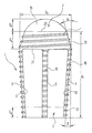
- FIG. 1 shows an intervertebral implant in a side view according to a first embodiment of the invention
- FIG. 2 is a bottom view of the intervertebral implant shown in FIG. 1 ;
- FIG. 3 schematically shows in a plan view two intervertebral implants implanted side by side between two vertebral bodies
- FIG. 4 shows on a slightly larger scale and in a side view an intervertebral implant between two vertebral bodies illustrated in section;
- FIG. 5 is a bottom view of an intervertebral implant according to a second embodiment of the invention.
- FIG. 1 shows an intervertebral implant designated in its entirety by reference numeral 1 .
- the implant comprises an (in the implanted state) ventrally-pointing head 2 and an (in the implanted state) dorsally-pointing base plate 3 which are connected to each other by four narrow struts 5 , 6 , 7 and 8 .
- Large-area windows 9 , 10 , 11 , 12 remain between the struts 5 , 6 , 7 , 8 , the head 2 and the base plate 3 .
- the head 2 of the intervertebral implant 1 comprises a conical portion 13 , which carries an external thread 14 , and a, viewed from the outside, convex protective cap 15 adjoining the conical portion 13 and forming the ventral end of the intervertebral implant 1 .
- the protective cap 15 which has a spherical cap surface in the embodiment shown, is polished for reasons which will be elucidated below. In particular, the cap 15 does not have any sharp edges.
- the arrow height D 3 of the protective cap 15 is at least 4 to 5 mm. The reason for this will also become clear below.
- the conical portion 13 has an axial length D.sub.4 which should not fall below 7 mm.
- the external thread 14 has at least three full turns inside the conical portion 13 .
- the angle ⁇ which the circumferential surface of the cone of the conical portion 13 encloses with an imaginary circumferential surface of a circular cylinder and which corresponds to half the cone angle is between 10° and 20°, preferably
- the struts 5 , 6 , 7 , 8 are also located on an imaginary surface of a circular cone which tapers in the opposite direction to the conical region 13 of the head 2 toward the dorsal end of the intervertebral implant 1 , located at the bottom in FIG. 1 .
- the angle ⁇ which the circumferential surface of this imaginary cone encloses with a circumferential surface of a circular cylinder and which corresponds to half the cone angle is about 6° or about 3°, depending on between which vertebral bodies the intervertebral implant 1 is to be inserted.
- the struts 5 , 6 , 7 , 8 also carry an external thread 16 which is constructed as a continuation of the external thread 14 on the conical region 13 of the head 2 .
- the struts 5 , 6 , 7 , 8 merge in one piece into the rounded corners of the base plate 3 , as becomes particularly clear from FIG. 2 .
- the bottom view of the base plate 3 is approximately square.
- the external thread 16 of the struts 5 , 6 , 7 , 8 continues in an external thread 17 on the rounded corners of the base plate 3 .
- FIG. 2 An application device for a screw-in instrument is worked into the lower side of the base plate 3 , as can be seen in FIG. 2 .
- the application device has the form of a cross groove 18 .
- the associated screw-in instrument which is not shown in the drawings, has a complementary cross-shaped axially extending projection and can be clicked into a latching device 19 which is schematically shown in the drawings as a circular hole.
- the latching device 19 is configured in such a way that the production of a connection between the screw-in instrument and the cross-groove 18 requires a positive action by the surgeon, and conversely release of the screw-in instrument from the base plate 3 can only take place with positive action by the surgeon and not unintentionally. Connections of this type are known per se and individually and so do not need to be described in more detail here.
- the axial extension D 5 of the base plate 3 should not fall below 4 mm.
- the intervertebral implant 1 does not substantially differ from patient to patient. Individual patient information flows into the dimensions of the intervertebral implant 1 in the following manner, however and must be taken preoperatively from CT scans or X-ray images:
- the axial distance D 1 between the dorsal, outer end face of the base plate 3 and the transition line 20 between the conical region 13 of the head 2 and the polished protective cap 15 corresponds, as may be gathered in particular from FIG. 4 , to the spacing between the dorsal outer edges of the vertebral bodies 30 , 31 to be connected and the opposing vertices 32 , 33 of the ventral edges of the vertebral bodies 30 , 31 in the lateral image.
- the implantation position of the intervertebral implant 1 is therefore such that the dorsal outer end face approximately aligns with the dorsal edges of the vertebral bodies 30 , 31 while the transition line 20 at the head 2 of the intervertebral implant 1 connects the vertices 32 , 33 of the two vertebral bodies 30 , 31 .
- the protective cap 15 of the head 2 projects in the process ventrally beyond the ventral edges of the vertebral bodies 30 , 31 .
- the intervertebral implant 1 can be made of different materials. On the one hand, as already described in the above-mentioned DE 199 57 339 C2, stainless steel or carbon-ceramic material may be considered. As a permanent material that remains in the body aluminium alloys, titanium and certain plastics materials, in particular polyisocyanate (PIC), are also suitable. Bioresorbable materials, such as polyactide in particular, in other words co-polymers of poly (L-lactide-co-D, L-lactide), as sold for example under the trade name Telamon®, may also be used, however.
- PIC polyisocyanate
- the largest diameter D 2 of the intervertebral implant 1 occurs, as becomes clear from the above description, at the transition line 21 between the head 2 and the struts 5 , 6 , 7 . It corresponds to the desired distraction between the adjacent vertebral bodies 30 , 31 and can be taken from the X-ray image, for example from neighbouring healthy segments. A whole set of intervertebral implants 1 which have to be kept ready by the surgeon is thus required with respect to dimension D 2 as well. A gradation of 2 mm is again sufficient. In practice dimensions D 2 of primarily 10, 12, 14 and 16 mm are considered.
- ventral end is not formed by a closed protective cap.
- the cap is replaced by a ring that has an opening and is convexly curved if viewed from the outside.
- the opening should not be larger than 5 mm.
- the outer face of such a protective ring pointing in the ventral direction should also be polished.
- the surgeon carries out spondylodesis using the described intervertebral implant 1 , of which two are required in each case, as follows:
- the individual items of information D 1 and D 2 of the intervertebral implants 1 to be used are determined preoperatively from the CT scans or X-ray images.
- the angle ⁇ is selected according to the desired lordosis of the vertebral bodies that are to be joined together.
- the operation is carried out by way of microsurgery from the dorsal side.
- the required access to the intervertebral space is obtained by partial removal of the small vertebral joints, wherein the Ligamentum flavum can largely be spared in the case of patients that have not been operated on already. This merely needs to be thinned out slightly from the outside to the inside, so that an inner layer is retained. Scar formation is thus avoided.
- the intervertebral space is then carefully freed from cartilage fractions of the deck plate and basal plate.
- the bone fractions are “freshened” in the process, i.e. thinly superficially abraded, wherein their load-bearing capacity is not damaged.
- a pre-distraction of the vertebral bodies 30 , 31 is then carried out using a distraction instrument which substantially attaches at the dorsal vertebral edges. The pre-distraction thus achieved is maintained by a sleeve provided with two attached spacer clips introduced into the intervertebral space when the distraction instrument is now removed again.
- a thread is then cut through this sleeve in the dorsal part of the intervertebral space.
- a first intervertebral implant 1 is now introduced through the sleeve head 2 first and by rotation screwed to the thread of the vertebral body 30 , 31 cut-in in advance, so that it moves axially in the ventral direction.
- the intervertebral implant 1 has been filled with spongiosa in advance.
- the intervertebral implant 1 is now rotated until the external thread 14 on the head 2 of the intervertebral implant 1 comes to rest against the compacta of the ventral circumference of the two vertebral bodies 30 , 31 .
- the external thread 14 cuts into the compacta of the ventral edges of the vertebral body 30 , 31 , wherein the conical shape of the conical region 13 of the head 2 provides a corresponding distraction of the ventral edges of the vertebral bodies 30 , 31 .
- the screwing-in movement of the intervertebral implant 1 is continued with X-ray observation until the transition line 20 comes to rest in the region of the vertices 32 , 33 of the two vertebral bodies 30 , 31 .
- the protective cap 15 of the head 2 may have pushed away the vena cava and the aorta, which extend in this direction, slightly in the ventral direction. However, the risk of injuring these vessels is small as the protective cap does not have any sharp edges.
- the remaining intervertebral space is now filled with spongiosa and a second intervertebral implant 1 ′ inserted next to the first intervertebral implant 1 in the above-described manner (cf. FIG. 3 ).
- the spacing between the two intervertebral implants 1 , 1 ′ should not be less than 1 cm.
- the second intervertebral implant 1 ′ has also already been filled with spongiosa before insertion.
- FIG. 5 is a bottom view similar to FIG. 2 of an intervertebral implant according to another embodiment of the invention.
- reference numerals augmented by 100 are used.
- the intervertebral implant 101 shown in FIG. 5 differs from the intervertebral implant 1 shown in FIGS. 1 to 4 only in that the base plate 103 is not square, but has a rectangular base geometry.
- the shorter lateral sides 131 , 132 have a lengths D 6
- the longer lateral sides 133 , 134 have a length D 7 >D 6 .
- the head of the intervertebral implant 101 has still a circular cross section.
- the struts 105 , 106 , 107 , 108 connecting the rotationally symmetric head with the rotationally asymmetric base plate 103 form different angles ⁇ in two orthogonal planes. More specifically, the angle ⁇ in one axial plane that vertically intersects the plane of the sheet is smaller than the angle ⁇ in a plane orthogonal thereto, i.e. in a plane intersecting the plane of the sheet horizontally.
- the selection of the angle ⁇ which finally becomes effective in that it determines the lordosis, depends on the angular orientation which the intervertebral implant 101 has in the intervertebral space after its insertion.
- the lordosis is, strictly speaking, not determined by the inclined struts 5 , 6 , 7 , 8 , but by the difference between the largest diameter of the head 2 and the diameter of the base plate 3 . This is because not the inclined struts 5 , 6 , 7 , 8 , but only the head 2 and the base plate 3 are usually in direct contact with the adjacent vertebral bodies.
- the two-fold rotational symmetry of the base plate 103 is mainly responsible for the different lordosis that may be obtained with the implant 103 in different angular positions.
- the grooves of the cross groove 118 have different lengths, too, and thus the cross groove does not have a fourfold, but only a twofold symmetry.
- the screw-in instrument which is not shown in the drawings, has a complementary cross-shaped axially extending projection with a twofold symmetry. This ensures that this instrument can be attached to the base plate 103 only in two different angular orientations. If the instrument is provided with an appropriate marking on its shaft, the surgeon can see with the help of the marking in which angular orientation the intervertebral implant 101 is positioned within the intervertebral space. For example, if the surgeon desires to obtain the first angle ⁇ 1 , he rotates the instruments until the marking indicates the correct position. If the surgeon desires to obtain the second angle ⁇ 2 , he simply rotates the instrument by 90°.
- the head has preferably a circular cross section, the provision of two different angles ⁇ 1 , ⁇ 2 does not impede the screwing-in of the intervertebral implant 101 into the intervertebral space. If the vertebral bodies 30 , 31 are pre-distracted by a sleeve as has been explained above, the screwing-in operation of the rotationally asymmetric central portion and base plate 103 are not impeded by the vertebral bodies 30 , 31 . After removal of the sleeve the vertebral bodies 30 , 31 will rest on the struts 105 , 106 , 107 , 108 with the angle ⁇ selected by the angular orientation of the intervertebral implant 103 .
- the base plate 103 as such may be rotationally symmetrical or may still have fourfold symmetry, but the struts 105 , 106 , 107 , 108 are connected to the base structure 103 such that nevertheless different angels ⁇ 1 , ⁇ 2 are obtained in two orthogonal planes, or the struts 105 , 106 , 107 , 108 are curved in different ways. It may also be envisioned to have three different angles ⁇ 1 , ⁇ 2 , ⁇ 3 that may be selected by rotating the implant by angles of 60°.
- a base plate having a hexagonal base geometry may be used in this context.
Landscapes
- Health & Medical Sciences (AREA)
- Engineering & Computer Science (AREA)
- Biomedical Technology (AREA)
- Neurology (AREA)
- Orthopedic Medicine & Surgery (AREA)
- Cardiology (AREA)
- Oral & Maxillofacial Surgery (AREA)
- Transplantation (AREA)
- Heart & Thoracic Surgery (AREA)
- Vascular Medicine (AREA)
- Life Sciences & Earth Sciences (AREA)
- Animal Behavior & Ethology (AREA)
- General Health & Medical Sciences (AREA)
- Public Health (AREA)
- Veterinary Medicine (AREA)
- Prostheses (AREA)
- Materials For Medical Uses (AREA)
- Surgical Instruments (AREA)
- Dental Preparations (AREA)
Applications Claiming Priority (1)
| Application Number | Priority Date | Filing Date | Title |
|---|---|---|---|
| PCT/EP2004/001359 WO2005082292A1 (de) | 2004-02-13 | 2004-02-13 | Zwischenwirbelimplantat sowie chirurgisches verfahren zur spondylodese der lendenwirbelsäule |
Related Parent Applications (1)
| Application Number | Title | Priority Date | Filing Date |
|---|---|---|---|
| PCT/EP2004/001359 Continuation-In-Part WO2005082292A1 (de) | 2004-02-13 | 2004-02-13 | Zwischenwirbelimplantat sowie chirurgisches verfahren zur spondylodese der lendenwirbelsäule |
Publications (2)
| Publication Number | Publication Date |
|---|---|
| US20070055374A1 US20070055374A1 (en) | 2007-03-08 |
| US8460380B2 true US8460380B2 (en) | 2013-06-11 |
Family
ID=34896208
Family Applications (1)
| Application Number | Title | Priority Date | Filing Date |
|---|---|---|---|
| US11/500,707 Expired - Fee Related US8460380B2 (en) | 2004-02-13 | 2006-08-08 | Intervertebral implant and surgical method for spondylodesis of a lumbar vertebral column |
Country Status (12)
| Country | Link |
|---|---|
| US (1) | US8460380B2 (ja) |
| EP (1) | EP1713421B1 (ja) |
| JP (1) | JP4620689B2 (ja) |
| CN (1) | CN100591305C (ja) |
| AT (1) | ATE489919T1 (ja) |
| AU (1) | AU2004316340B2 (ja) |
| BR (1) | BRPI0418538A (ja) |
| CA (1) | CA2555405C (ja) |
| DE (1) | DE502004011964D1 (ja) |
| DK (1) | DK1713421T3 (ja) |
| ES (1) | ES2357270T3 (ja) |
| WO (1) | WO2005082292A1 (ja) |
Cited By (1)
| Publication number | Priority date | Publication date | Assignee | Title |
|---|---|---|---|---|
| US20170156876A1 (en) * | 2014-06-06 | 2017-06-08 | In2Bones | Surgical implant, and associated installation tool, surgical kit and method of production |
Families Citing this family (25)
| Publication number | Priority date | Publication date | Assignee | Title |
|---|---|---|---|---|
| AU2003248714A1 (en) * | 2002-06-17 | 2003-12-31 | Trimedyne, Inc. | Devices and methods for minimally invasive treatment of degenerated spinal discs |
| US7648509B2 (en) * | 2003-03-10 | 2010-01-19 | Ilion Medical Llc | Sacroiliac joint immobilization |
| ATE489919T1 (de) | 2004-02-13 | 2010-12-15 | Jun Franz Copf | Zwischenwirbelimplantat zur spondylodese der lendenwirbelsäule |
| US20090024174A1 (en) * | 2007-07-17 | 2009-01-22 | Stark John G | Bone screws and particular applications to sacroiliac joint fusion |
| US8740912B2 (en) | 2008-02-27 | 2014-06-03 | Ilion Medical Llc | Tools for performing less invasive orthopedic joint procedures |
| PL215752B1 (pl) * | 2009-09-28 | 2014-01-31 | Lfc Spolka Z Ograniczona Odpowiedzialnoscia | Urzadzenie do chirurgicznego przemieszczania kregów |
| CA3002234C (en) | 2010-01-13 | 2020-07-28 | Jcbd, Llc | Sacroiliac joint fixation fusion system |
| US9333090B2 (en) | 2010-01-13 | 2016-05-10 | Jcbd, Llc | Systems for and methods of fusing a sacroiliac joint |
| US9788961B2 (en) | 2010-01-13 | 2017-10-17 | Jcbd, Llc | Sacroiliac joint implant system |
| US9421109B2 (en) | 2010-01-13 | 2016-08-23 | Jcbd, Llc | Systems and methods of fusing a sacroiliac joint |
| WO2014015309A1 (en) | 2012-07-20 | 2014-01-23 | Jcbd, Llc | Orthopedic anchoring system and methods |
| US9381045B2 (en) | 2010-01-13 | 2016-07-05 | Jcbd, Llc | Sacroiliac joint implant and sacroiliac joint instrument for fusing a sacroiliac joint |
| EP2538885A1 (en) | 2010-02-26 | 2013-01-02 | spontech spine intelligence group AG | Computer program for spine mobility simulation and spine simulation method |
| DE202010011948U1 (de) | 2010-08-28 | 2010-10-28 | Spontech Spine Intelligence Ag | Implantat-System für die Fusion von Wirbelkörpern |
| DE202010011993U1 (de) | 2010-08-30 | 2010-10-28 | Spontech Spine Intelligence Ag | Instrumentarium zum Eindrehen eines Impantats in ein Bandscheibenfach |
| DE102010035832A1 (de) | 2010-08-30 | 2012-03-01 | Spontech Spine Intelligence Group Ag | Instrumentarium zum Eindrehen eines Implantats in ein Bandscheibenfach |
| US8900309B2 (en) | 2010-08-31 | 2014-12-02 | Meditech Spine, Llc | Spinal implants |
| DE102011106172A1 (de) | 2011-07-01 | 2013-01-03 | Spontech Spine Intelligence Group Ag | System zur Fixierung zweier benachbarter Wirbel |
| US9717539B2 (en) | 2013-07-30 | 2017-08-01 | Jcbd, Llc | Implants, systems, and methods for fusing a sacroiliac joint |
| US9826986B2 (en) | 2013-07-30 | 2017-11-28 | Jcbd, Llc | Systems for and methods of preparing a sacroiliac joint for fusion |
| US10245087B2 (en) | 2013-03-15 | 2019-04-02 | Jcbd, Llc | Systems and methods for fusing a sacroiliac joint and anchoring an orthopedic appliance |
| US9510872B2 (en) | 2013-03-15 | 2016-12-06 | Jcbd, Llc | Spinal stabilization system |
| WO2015017593A1 (en) | 2013-07-30 | 2015-02-05 | Jcbd, Llc | Systems for and methods of fusing a sacroiliac joint |
| US9801546B2 (en) | 2014-05-27 | 2017-10-31 | Jcbd, Llc | Systems for and methods of diagnosing and treating a sacroiliac joint disorder |
| US10603055B2 (en) | 2017-09-15 | 2020-03-31 | Jcbd, Llc | Systems for and methods of preparing and fusing a sacroiliac joint |
Citations (64)
| Publication number | Priority date | Publication date | Assignee | Title |
|---|---|---|---|---|
| EP0637440A1 (fr) | 1993-08-06 | 1995-02-08 | Advanced Technical Fabrication | Implant intersomatique pour colonne vertebrale |
| FR2710519A1 (fr) | 1993-09-29 | 1995-04-07 | Robine Dominique | Cage intersomatique lombaire (CH). |
| WO1995025487A1 (en) | 1994-03-18 | 1995-09-28 | Madhavan Pisharodi | Middle expanded, removable intervertebral disk stabilizer and method of lumbar intervertebral disk stabilization |
| US5458638A (en) | 1989-07-06 | 1995-10-17 | Spine-Tech, Inc. | Non-threaded spinal implant |
| DE29600879U1 (de) | 1996-01-19 | 1996-03-28 | Howmedica GmbH, 24232 Schönkirchen | Wirbelsäulenimplantat |
| EP0716840A2 (en) | 1994-12-12 | 1996-06-19 | Surgical Dynamics, Inc. | Conically-shaped fusion cage and method of implantation |
| FR2729557A1 (fr) | 1995-01-24 | 1996-07-26 | Stryker Corp | Implant de type cage intersomatique, et instrumentation et procede pour sa pose |
| WO1996027348A1 (de) | 1995-03-08 | 1996-09-12 | Synthes Ag, Chur | Zwischenwirbel-implantat |
| FR2736538A1 (fr) | 1995-07-12 | 1997-01-17 | Gastambide Daniel | Cage intersomatique pour rachis lombaire |
| EP0781113A1 (en) | 1994-09-15 | 1997-07-02 | Surgical Dynamics, Inc. | Conically-shaped anterior fusion cage and method of implantation |
| DE29712331U1 (de) | 1997-02-28 | 1997-10-02 | Metrimed Orvosi Müszergyártó KFT, Hódmezövásárhely | Implantat zur Befestigung von Wirbeln |
| FR2753368A1 (fr) | 1996-09-13 | 1998-03-20 | Chauvin Jean Luc | Cage d'osteosynthese expansive |
| EP0831759A1 (en) | 1995-06-07 | 1998-04-01 | MICHELSON, Gary Karlin | Threaded frusto-conical interbody spinal fusion implants |
| EP0836457A1 (en) | 1995-06-07 | 1998-04-22 | MICHELSON, Gary Karlin | Frusto-conical interbody spinal fusion implants |
| US5749916A (en) | 1997-01-21 | 1998-05-12 | Spinal Innovations | Fusion implant |
| EP0844856A2 (de) | 1995-08-11 | 1998-06-03 | Bernhard Zientek | Zwischenwirbelimplantat, verfahren zum aufweiten und instrumente zum implantieren eines zwischenwirbelimplantats |
| US5766252A (en) | 1995-01-24 | 1998-06-16 | Osteonics Corp. | Interbody spinal prosthetic implant and method |
| FR2760355A1 (fr) | 1997-03-07 | 1998-09-11 | Serge Schrayer | Dispositif formant cage intersomatique a solidarisation provisoire interne d'un outil de vissage |
| FR2764795A1 (fr) | 1997-06-19 | 1998-12-24 | Sarl Sra | Cage intersomatique d'immobilisation du rachis et materiel ancillaire associe |
| US5865847A (en) | 1997-03-06 | 1999-02-02 | Sulzer Spine-Tech Inc. | Lordotic spinal implant |
| US5885299A (en) | 1994-09-15 | 1999-03-23 | Surgical Dynamics, Inc. | Apparatus and method for implant insertion |
| US5888228A (en) * | 1995-10-20 | 1999-03-30 | Synthes (U.S.A.) | Intervertebral implant with cage and rotating element |
| US5895427A (en) | 1989-07-06 | 1999-04-20 | Sulzer Spine-Tech Inc. | Method for spinal fixation |
| EP0912147A1 (de) | 1996-07-15 | 1999-05-06 | Aesculap AG & Co. KG | Implantat zur wirbelkörperfusion |
| US5980522A (en) * | 1994-07-22 | 1999-11-09 | Koros; Tibor | Expandable spinal implants |
| US6033405A (en) | 1994-09-15 | 2000-03-07 | Surgical Dynamics, Inc. | Apparatus and method for implant insertion |
| GB2345639A (en) | 1999-01-16 | 2000-07-19 | Corin Spinal Systems Limited | A spinal fusion implant |
| FR2789297A1 (fr) | 1999-02-04 | 2000-08-11 | Aesculap Ag & Co Kg | Vis de liaison rehabitable pour l'arthrodese d'une articulation osseuse, notamment pour la stabilisation de deux vertebres |
| DE20012236U1 (de) | 2000-07-14 | 2000-10-12 | Corin Spinal Systems Ltd., Cirencester, Gloucestershire | Implantat zur operativen Wirbelsäulenversteifung |
| US6168631B1 (en) | 1997-08-29 | 2001-01-02 | Kinetikos Medical, Inc. | Subtalar implant system and method for insertion and removal |
| US6210412B1 (en) | 1988-06-13 | 2001-04-03 | Gary Karlin Michelson | Method for inserting frusto-conical interbody spinal fusion implants |
| EP1103235A2 (de) | 1999-11-29 | 2001-05-30 | Franz Copf | Cageelement, sowie Satz von Cageelementen |
| EP1107711A1 (en) | 1998-08-28 | 2001-06-20 | Societe De Fabrication De Materiel Orthopedique Sofamor | Expandable interbody fusion cage |
| DE20004692U1 (de) | 2000-03-14 | 2001-07-26 | Sofamor Danek GmbH, 94469 Deggendorf | Wirbelimplantat zum Einschrauben in einen Wirbelzwischenraum |
| JP2001238891A (ja) | 2000-02-02 | 2001-09-04 | Chiichi Rin | 側片を有する脊椎の固定復位器 |
| US6290724B1 (en) * | 1998-05-27 | 2001-09-18 | Nuvasive, Inc. | Methods for separating and stabilizing adjacent vertebrae |
| US6447545B1 (en) | 2000-07-01 | 2002-09-10 | George W. Bagby | Self-aligning bone implant |
| US20020193881A1 (en) * | 1999-02-04 | 2002-12-19 | Shapiro David E. | Interbody fusion device with anti-rotation features |
| US20030009222A1 (en) | 1966-03-14 | 2003-01-09 | Hans-Joachim Fruh | Synthetic threaded vertebral implant |
| US6527773B1 (en) | 1999-10-07 | 2003-03-04 | Osteotech, Inc. | Cervical dowel and insertion tool |
| EP1290985A2 (en) | 2001-08-16 | 2003-03-12 | Iql Industrias Quirurgicas De Levante S.L. | Intersomatic cage for posterior fusion surgery to the lumbar column and for surgery involving the insertion of a transforaminal implant |
| US6562039B1 (en) * | 1999-12-10 | 2003-05-13 | Chao-Jan Wang | Spinal fixation and retrieval device |
| US6613091B1 (en) * | 1995-03-27 | 2003-09-02 | Sdgi Holdings, Inc. | Spinal fusion implants and tools for insertion and revision |
| US20030171813A1 (en) * | 2002-03-05 | 2003-09-11 | P. Douglas Kiester | Method and apparatus for providing an expandable spinal fusion cage |
| FR2841124A1 (fr) | 2002-06-25 | 2003-12-26 | Eurosurgical | Cage intersomatique reversible et son dispositif de mise en place entre le corps vertebraux d'une colonne vertebrale |
| EP1408891A1 (en) | 2001-07-24 | 2004-04-21 | Maurizio Fornari | Device for intersomatic stabilization using a mini-invasive approach |
| US6726722B2 (en) * | 2000-10-24 | 2004-04-27 | Howmedica Osteonics Corp. | Threaded apparatus for fusing adjacent bone structure |
| EP1415622A1 (de) | 2002-10-16 | 2004-05-06 | Advanced Medical Technologies AG | Spreizimplantat zur Anordnung zwischen Wirbeln der Wirbelsäule |
| EP1415623A1 (de) | 2002-10-16 | 2004-05-06 | Advanced Medical Technologies AG | Implantat für die Anordnung zwischen Wirbeln der Wirbelsäule |
| FR2848414A1 (fr) | 2002-12-17 | 2004-06-18 | Vitatech | Implant intersomatique pour vertebres |
| US6855166B2 (en) * | 1998-03-20 | 2005-02-15 | Zimmer Spine, Inc. | Intevertebral implant with reduced contact area and method |
| EP1525863A2 (en) | 1995-02-17 | 2005-04-27 | SDGI Holdings, Inc. | Arcuate ratcheted spinal fusion implant |
| US6923830B2 (en) * | 2002-02-02 | 2005-08-02 | Gary K. Michelson | Spinal fusion implant having deployable bone engaging projections |
| FR2870449A1 (fr) | 2004-05-19 | 2005-11-25 | Medicrea Sa | Implant intervertebral |
| EP1635743A1 (de) | 2003-06-24 | 2006-03-22 | Synthes AG Chur | Implantat für den zwischenwirbelraum |
| US20060116767A1 (en) * | 2002-11-14 | 2006-06-01 | Sepitec Foundation | Implant Used in Procedures for Stiffening the Vertebral Column |
| EP1713421A1 (de) | 2004-02-13 | 2006-10-25 | Copf jun., Franz | Zwischenwirbelimplantat sowie chirurgisches verfahren zur spondylodese der lendenwirbelsäule |
| EP1740129A1 (de) | 2004-04-26 | 2007-01-10 | Synthes GmbH | Zwischenwirbelprothese oder bandscheibenprothese |
| US7291149B1 (en) | 1995-06-07 | 2007-11-06 | Warsaw Orthopedic, Inc. | Method for inserting interbody spinal fusion implants |
| US20070267365A1 (en) | 2006-05-19 | 2007-11-22 | Kabushiki-Kaisha Spin | Merchandise display system |
| US7331996B2 (en) * | 2002-08-20 | 2008-02-19 | Showa Ika Kohgyo Co., Ltd. | Intervertebral spacer |
| US7400930B2 (en) * | 1996-08-13 | 2008-07-15 | Oratec Interventions, Inc. | Method for treating intervertebral discs |
| FR2920665A1 (fr) | 2007-09-10 | 2009-03-13 | Kiscomedica Sa | Cage intervertebrale. |
| US7655046B2 (en) * | 2005-01-20 | 2010-02-02 | Warsaw Orthopedic, Inc. | Expandable spinal fusion cage and associated instrumentation |
Family Cites Families (2)
| Publication number | Priority date | Publication date | Assignee | Title |
|---|---|---|---|---|
| US5782919A (en) * | 1995-03-27 | 1998-07-21 | Sdgi Holdings, Inc. | Interbody fusion device and method for restoration of normal spinal anatomy |
| JP3909323B2 (ja) * | 2003-11-04 | 2007-04-25 | キョンウォン・メディカル・カンパニー・リミティッド | 膨張型骨接合ケージ |
-
2004
- 2004-02-13 AT AT04710828T patent/ATE489919T1/de active
- 2004-02-13 BR BRPI0418538-2A patent/BRPI0418538A/pt not_active IP Right Cessation
- 2004-02-13 DK DK04710828.7T patent/DK1713421T3/da active
- 2004-02-13 WO PCT/EP2004/001359 patent/WO2005082292A1/de not_active Ceased
- 2004-02-13 JP JP2006552466A patent/JP4620689B2/ja not_active Expired - Fee Related
- 2004-02-13 CA CA2555405A patent/CA2555405C/en not_active Expired - Fee Related
- 2004-02-13 ES ES04710828T patent/ES2357270T3/es not_active Expired - Lifetime
- 2004-02-13 AU AU2004316340A patent/AU2004316340B2/en not_active Ceased
- 2004-02-13 EP EP04710828A patent/EP1713421B1/de not_active Expired - Lifetime
- 2004-02-13 DE DE502004011964T patent/DE502004011964D1/de not_active Expired - Lifetime
- 2004-02-13 CN CN200480041640A patent/CN100591305C/zh not_active Expired - Fee Related
-
2006
- 2006-08-08 US US11/500,707 patent/US8460380B2/en not_active Expired - Fee Related
Patent Citations (116)
| Publication number | Priority date | Publication date | Assignee | Title |
|---|---|---|---|---|
| US20030009222A1 (en) | 1966-03-14 | 2003-01-09 | Hans-Joachim Fruh | Synthetic threaded vertebral implant |
| US6210412B1 (en) | 1988-06-13 | 2001-04-03 | Gary Karlin Michelson | Method for inserting frusto-conical interbody spinal fusion implants |
| US6923810B1 (en) * | 1988-06-13 | 2005-08-02 | Gary Karlin Michelson | Frusto-conical interbody spinal fusion implants |
| US5895427A (en) | 1989-07-06 | 1999-04-20 | Sulzer Spine-Tech Inc. | Method for spinal fixation |
| US5458638A (en) | 1989-07-06 | 1995-10-17 | Spine-Tech, Inc. | Non-threaded spinal implant |
| US6287343B1 (en) | 1989-07-06 | 2001-09-11 | Sulzer Spine-Tech, Inc. | Threaded spinal implant with bone ingrowth openings |
| US5489308A (en) | 1989-07-06 | 1996-02-06 | Spine-Tech, Inc. | Spinal implant |
| US6149686A (en) | 1989-07-06 | 2000-11-21 | Sulzer Spine-Tech Inc. | Threaded spinal implant with bone ingrowth openings |
| US20020183846A1 (en) * | 1989-07-06 | 2002-12-05 | Sulzer Spine-Tech Inc. | Spinal implant |
| US6391058B1 (en) | 1989-07-06 | 2002-05-21 | Sulzer Spine-Tech Inc. | Threaded spinal implant with convex trailing surface |
| US5683463A (en) | 1993-08-06 | 1997-11-04 | Advanced Technical Fabrication | Intersomatic vertebral column implant |
| EP0637440A1 (fr) | 1993-08-06 | 1995-02-08 | Advanced Technical Fabrication | Implant intersomatique pour colonne vertebrale |
| FR2710519A1 (fr) | 1993-09-29 | 1995-04-07 | Robine Dominique | Cage intersomatique lombaire (CH). |
| US6093207A (en) * | 1994-03-18 | 2000-07-25 | Pisharodi; Madhavan | Middle expanded, removable intervertebral disk stabilizer disk |
| WO1995025487A1 (en) | 1994-03-18 | 1995-09-28 | Madhavan Pisharodi | Middle expanded, removable intervertebral disk stabilizer and method of lumbar intervertebral disk stabilization |
| US5980522A (en) * | 1994-07-22 | 1999-11-09 | Koros; Tibor | Expandable spinal implants |
| EP0781113A1 (en) | 1994-09-15 | 1997-07-02 | Surgical Dynamics, Inc. | Conically-shaped anterior fusion cage and method of implantation |
| US5885299A (en) | 1994-09-15 | 1999-03-23 | Surgical Dynamics, Inc. | Apparatus and method for implant insertion |
| US6033405A (en) | 1994-09-15 | 2000-03-07 | Surgical Dynamics, Inc. | Apparatus and method for implant insertion |
| US5906616A (en) * | 1994-09-15 | 1999-05-25 | Surgical Dynamics, Inc. | Conically shaped anterior fusion cage and method of implantation |
| US7608105B2 (en) * | 1994-09-15 | 2009-10-27 | Howmedica Osteonics Corp. | Methods of inserting conically-shaped fusion cages |
| EP1175878A2 (en) | 1994-12-12 | 2002-01-30 | Surgical Dynamics, Inc. | Conically-shaped fusion cage |
| EP0716840A2 (en) | 1994-12-12 | 1996-06-19 | Surgical Dynamics, Inc. | Conically-shaped fusion cage and method of implantation |
| FR2729557A1 (fr) | 1995-01-24 | 1996-07-26 | Stryker Corp | Implant de type cage intersomatique, et instrumentation et procede pour sa pose |
| US5766252A (en) | 1995-01-24 | 1998-06-16 | Osteonics Corp. | Interbody spinal prosthetic implant and method |
| WO1996022747A1 (fr) | 1995-01-24 | 1996-08-01 | Stryker Corporation | Implant de type cage intersomatique, et instrumentation et procede pour sa pose |
| EP1525863A2 (en) | 1995-02-17 | 2005-04-27 | SDGI Holdings, Inc. | Arcuate ratcheted spinal fusion implant |
| EP0758874A1 (de) | 1995-03-08 | 1997-02-26 | Synthes AG, Chur | Zwischenwirbel-implantat |
| US6059829A (en) | 1995-03-08 | 2000-05-09 | Synthese | Intervertebral implant |
| WO1996027348A1 (de) | 1995-03-08 | 1996-09-12 | Synthes Ag, Chur | Zwischenwirbel-implantat |
| US6613091B1 (en) * | 1995-03-27 | 2003-09-02 | Sdgi Holdings, Inc. | Spinal fusion implants and tools for insertion and revision |
| EP0836457A1 (en) | 1995-06-07 | 1998-04-22 | MICHELSON, Gary Karlin | Frusto-conical interbody spinal fusion implants |
| US7291149B1 (en) | 1995-06-07 | 2007-11-06 | Warsaw Orthopedic, Inc. | Method for inserting interbody spinal fusion implants |
| EP0831759A1 (en) | 1995-06-07 | 1998-04-01 | MICHELSON, Gary Karlin | Threaded frusto-conical interbody spinal fusion implants |
| EP1442732A1 (en) | 1995-06-07 | 2004-08-04 | MICHELSON, Gary Karlin | An interbody spinal fusion implant having bone engaging means with an increasing height |
| EP1400221A2 (en) | 1995-06-07 | 2004-03-24 | MICHELSON, Gary Karlin | An interbody spinal fusion implant having variable height threads |
| US20050165399A1 (en) | 1995-06-07 | 2005-07-28 | Michelson Gary K. | Frusto-conical spinal implant |
| US20050165489A1 (en) | 1995-06-07 | 2005-07-28 | Michelson Gary K. | Frusto-conical spinal implant |
| FR2736538A1 (fr) | 1995-07-12 | 1997-01-17 | Gastambide Daniel | Cage intersomatique pour rachis lombaire |
| EP0844856A2 (de) | 1995-08-11 | 1998-06-03 | Bernhard Zientek | Zwischenwirbelimplantat, verfahren zum aufweiten und instrumente zum implantieren eines zwischenwirbelimplantats |
| US6179873B1 (en) | 1995-08-11 | 2001-01-30 | Bernhard Zientek | Intervertebral implant, process for widening and instruments for implanting an intervertebral implant |
| US5888228A (en) * | 1995-10-20 | 1999-03-30 | Synthes (U.S.A.) | Intervertebral implant with cage and rotating element |
| EP0784967A2 (en) | 1996-01-19 | 1997-07-23 | Howmedica GmbH | Spine implant |
| DE29600879U1 (de) | 1996-01-19 | 1996-03-28 | Howmedica GmbH, 24232 Schönkirchen | Wirbelsäulenimplantat |
| US6019760A (en) | 1996-01-19 | 2000-02-01 | Howmedica Gmbh | Spine implant |
| US6210442B1 (en) | 1996-07-15 | 2001-04-03 | Aesculap Ag & Co. Kg | Implant for vertebral body fusion |
| EP0912147A1 (de) | 1996-07-15 | 1999-05-06 | Aesculap AG & Co. KG | Implantat zur wirbelkörperfusion |
| US7400930B2 (en) * | 1996-08-13 | 2008-07-15 | Oratec Interventions, Inc. | Method for treating intervertebral discs |
| US6129763A (en) | 1996-09-13 | 2000-10-10 | Chauvin; Jean-Luc | Expandable osteosynthesis cage |
| EP1014899A1 (fr) | 1996-09-13 | 2000-07-05 | Cage Concepts LLC | Cage d'osteosynthese expansive |
| US6371989B1 (en) | 1996-09-13 | 2002-04-16 | Jean-Luc Chauvin | Method of providing proper vertebral spacing |
| FR2753368A1 (fr) | 1996-09-13 | 1998-03-20 | Chauvin Jean Luc | Cage d'osteosynthese expansive |
| EP0853932A2 (en) | 1997-01-21 | 1998-07-22 | Spinal Innovations | Fusion implant |
| US5749916A (en) | 1997-01-21 | 1998-05-12 | Spinal Innovations | Fusion implant |
| US5976187A (en) | 1997-01-21 | 1999-11-02 | Spinal Innovations, L.L.C. | Fusion implant |
| DE29712331U1 (de) | 1997-02-28 | 1997-10-02 | Metrimed Orvosi Müszergyártó KFT, Hódmezövásárhely | Implantat zur Befestigung von Wirbeln |
| EP1011481A2 (en) | 1997-03-06 | 2000-06-28 | Sulzer Spine-Tech Inc. | Lordotic spinal implant |
| US5865847A (en) | 1997-03-06 | 1999-02-02 | Sulzer Spine-Tech Inc. | Lordotic spinal implant |
| US20030045938A1 (en) * | 1997-03-06 | 2003-03-06 | Sulzer Spine-Tech Inc. | Lordotic spinal implant |
| US5897593A (en) | 1997-03-06 | 1999-04-27 | Sulzer Spine-Tech Inc. | Lordotic spinal implant |
| US6165219A (en) | 1997-03-06 | 2000-12-26 | Sulzer Spine-Tech Inc. | Lordotic spinal implant |
| US7267689B2 (en) * | 1997-03-06 | 2007-09-11 | Zimmer Spine, Inc. | Lordotic spinal implant |
| US6740091B2 (en) | 1997-03-06 | 2004-05-25 | Sulzer Spine-Tech Inc. | Lordotic spinal implant |
| US6120506A (en) | 1997-03-06 | 2000-09-19 | Sulzer Spine-Tech Inc. | Lordotic spinal implant |
| FR2760355A1 (fr) | 1997-03-07 | 1998-09-11 | Serge Schrayer | Dispositif formant cage intersomatique a solidarisation provisoire interne d'un outil de vissage |
| FR2764795A1 (fr) | 1997-06-19 | 1998-12-24 | Sarl Sra | Cage intersomatique d'immobilisation du rachis et materiel ancillaire associe |
| US6168631B1 (en) | 1997-08-29 | 2001-01-02 | Kinetikos Medical, Inc. | Subtalar implant system and method for insertion and removal |
| US6855166B2 (en) * | 1998-03-20 | 2005-02-15 | Zimmer Spine, Inc. | Intevertebral implant with reduced contact area and method |
| US6290724B1 (en) * | 1998-05-27 | 2001-09-18 | Nuvasive, Inc. | Methods for separating and stabilizing adjacent vertebrae |
| EP1107711A1 (en) | 1998-08-28 | 2001-06-20 | Societe De Fabrication De Materiel Orthopedique Sofamor | Expandable interbody fusion cage |
| US6436140B1 (en) | 1998-08-28 | 2002-08-20 | Sofamor S.N.C. | Expandable interbody fusion cage and method for insertion |
| US7431735B2 (en) | 1998-08-28 | 2008-10-07 | Sofamor S.N.C. | Expandable interbody fusion cage |
| GB2345639A (en) | 1999-01-16 | 2000-07-19 | Corin Spinal Systems Limited | A spinal fusion implant |
| EP1148849A1 (fr) | 1999-02-04 | 2001-10-31 | Aesculap AG & Co. KG | Vis de liaison rehabitable pour l'arthrodese d'une articulation osseuse, notamment pour la stabilisation de deux vertebres |
| FR2789297A1 (fr) | 1999-02-04 | 2000-08-11 | Aesculap Ag & Co Kg | Vis de liaison rehabitable pour l'arthrodese d'une articulation osseuse, notamment pour la stabilisation de deux vertebres |
| US20020193881A1 (en) * | 1999-02-04 | 2002-12-19 | Shapiro David E. | Interbody fusion device with anti-rotation features |
| US6733504B2 (en) | 1999-10-07 | 2004-05-11 | Osteotech, Inc. | Cervical dowel and insertion tool |
| US6527773B1 (en) | 1999-10-07 | 2003-03-04 | Osteotech, Inc. | Cervical dowel and insertion tool |
| EP1103235A2 (de) | 1999-11-29 | 2001-05-30 | Franz Copf | Cageelement, sowie Satz von Cageelementen |
| DE19957339C2 (de) | 1999-11-29 | 2002-03-28 | Franz Copf | Cageelement, sowie Satz von Cageelementen |
| US6562039B1 (en) * | 1999-12-10 | 2003-05-13 | Chao-Jan Wang | Spinal fixation and retrieval device |
| US6730125B1 (en) * | 2000-02-02 | 2004-05-04 | Chih-I Lin | Spinal fixation and retrieval device having side pieces |
| JP2001238891A (ja) | 2000-02-02 | 2001-09-04 | Chiichi Rin | 側片を有する脊椎の固定復位器 |
| DE20004692U1 (de) | 2000-03-14 | 2001-07-26 | Sofamor Danek GmbH, 94469 Deggendorf | Wirbelimplantat zum Einschrauben in einen Wirbelzwischenraum |
| EP1265561A1 (en) | 2000-03-14 | 2002-12-18 | SDGI Holdings, Inc. | Synthetic threaded vertebral implant |
| US6447545B1 (en) | 2000-07-01 | 2002-09-10 | George W. Bagby | Self-aligning bone implant |
| EP1326559A2 (en) | 2000-07-01 | 2003-07-16 | George W. Bagby | Self-aligning and tapping bone joining implant |
| DE20012236U1 (de) | 2000-07-14 | 2000-10-12 | Corin Spinal Systems Ltd., Cirencester, Gloucestershire | Implantat zur operativen Wirbelsäulenversteifung |
| US6726722B2 (en) * | 2000-10-24 | 2004-04-27 | Howmedica Osteonics Corp. | Threaded apparatus for fusing adjacent bone structure |
| EP1408891A1 (en) | 2001-07-24 | 2004-04-21 | Maurizio Fornari | Device for intersomatic stabilization using a mini-invasive approach |
| US20040267365A1 (en) | 2001-07-24 | 2004-12-30 | Maurizio Fornari | Device for intersomatic stabilization using a mini-invasive approach |
| EP1290985A2 (en) | 2001-08-16 | 2003-03-12 | Iql Industrias Quirurgicas De Levante S.L. | Intersomatic cage for posterior fusion surgery to the lumbar column and for surgery involving the insertion of a transforaminal implant |
| EP1889587A2 (en) | 2001-08-16 | 2008-02-20 | Biomet Spain Orthopaedics S.L. | Intersomatic cage for posterior fusion surgery to the lumbar column and for surgery involving the insertion of a transforaminal implant |
| US6923830B2 (en) * | 2002-02-02 | 2005-08-02 | Gary K. Michelson | Spinal fusion implant having deployable bone engaging projections |
| US20030171813A1 (en) * | 2002-03-05 | 2003-09-11 | P. Douglas Kiester | Method and apparatus for providing an expandable spinal fusion cage |
| FR2841124A1 (fr) | 2002-06-25 | 2003-12-26 | Eurosurgical | Cage intersomatique reversible et son dispositif de mise en place entre le corps vertebraux d'une colonne vertebrale |
| WO2004000176A1 (fr) | 2002-06-25 | 2003-12-31 | Eurosurgical Sa | Cage intersomatique reversible et son dispositif de mise en place entre les corps vertebraux d'une colonne vertebrale |
| US7331996B2 (en) * | 2002-08-20 | 2008-02-19 | Showa Ika Kohgyo Co., Ltd. | Intervertebral spacer |
| EP1415623A1 (de) | 2002-10-16 | 2004-05-06 | Advanced Medical Technologies AG | Implantat für die Anordnung zwischen Wirbeln der Wirbelsäule |
| EP1415622A1 (de) | 2002-10-16 | 2004-05-06 | Advanced Medical Technologies AG | Spreizimplantat zur Anordnung zwischen Wirbeln der Wirbelsäule |
| US7220280B2 (en) | 2002-10-16 | 2007-05-22 | Advanced Medical Technologies Ag | Spreader implant for placement between vertebrae |
| US20040127993A1 (en) | 2002-10-16 | 2004-07-01 | Erich Kast | Spreader implant for placement between vertebrae |
| US20060116767A1 (en) * | 2002-11-14 | 2006-06-01 | Sepitec Foundation | Implant Used in Procedures for Stiffening the Vertebral Column |
| US20060085067A1 (en) | 2002-12-17 | 2006-04-20 | Thomas Gradel | Intervertebral implant |
| EP1585466A1 (fr) | 2002-12-17 | 2005-10-19 | Vitatech | Implant intersomatique pour vertebres |
| FR2848414A1 (fr) | 2002-12-17 | 2004-06-18 | Vitatech | Implant intersomatique pour vertebres |
| US20060195190A1 (en) | 2003-06-24 | 2006-08-31 | Beat Lechmann | Implant for intervertebral space |
| EP1635743A1 (de) | 2003-06-24 | 2006-03-22 | Synthes AG Chur | Implantat für den zwischenwirbelraum |
| US20070055374A1 (en) | 2004-02-13 | 2007-03-08 | Copf, Franz, Jr. | Intervertebral implant and surgical method for spondylodesis of a lumbar vertebral column |
| EP1713421A1 (de) | 2004-02-13 | 2006-10-25 | Copf jun., Franz | Zwischenwirbelimplantat sowie chirurgisches verfahren zur spondylodese der lendenwirbelsäule |
| US20080133015A1 (en) | 2004-04-26 | 2008-06-05 | Beat Lechmann | Intervertebral Prosthesis or Disk Prosthesis |
| EP1740129A1 (de) | 2004-04-26 | 2007-01-10 | Synthes GmbH | Zwischenwirbelprothese oder bandscheibenprothese |
| FR2870449A1 (fr) | 2004-05-19 | 2005-11-25 | Medicrea Sa | Implant intervertebral |
| US7655046B2 (en) * | 2005-01-20 | 2010-02-02 | Warsaw Orthopedic, Inc. | Expandable spinal fusion cage and associated instrumentation |
| US20070267365A1 (en) | 2006-05-19 | 2007-11-22 | Kabushiki-Kaisha Spin | Merchandise display system |
| FR2920665A1 (fr) | 2007-09-10 | 2009-03-13 | Kiscomedica Sa | Cage intervertebrale. |
Non-Patent Citations (1)
| Title |
|---|
| PCT International Search Report dated Aug. 5, 2004. |
Cited By (2)
| Publication number | Priority date | Publication date | Assignee | Title |
|---|---|---|---|---|
| US20170156876A1 (en) * | 2014-06-06 | 2017-06-08 | In2Bones | Surgical implant, and associated installation tool, surgical kit and method of production |
| US10136999B2 (en) * | 2014-06-06 | 2018-11-27 | In2Bones | Surgical implant, and associated installation tool, surgical kit and method of production |
Also Published As
| Publication number | Publication date |
|---|---|
| AU2004316340B2 (en) | 2011-03-10 |
| ES2357270T3 (es) | 2011-04-20 |
| US20070055374A1 (en) | 2007-03-08 |
| EP1713421A1 (de) | 2006-10-25 |
| CA2555405C (en) | 2011-01-18 |
| CN1913845A (zh) | 2007-02-14 |
| CN100591305C (zh) | 2010-02-24 |
| BRPI0418538A (pt) | 2007-05-22 |
| CA2555405A1 (en) | 2005-09-09 |
| AU2004316340A1 (en) | 2005-09-09 |
| WO2005082292A1 (de) | 2005-09-09 |
| AU2004316340A2 (en) | 2005-09-09 |
| JP4620689B2 (ja) | 2011-01-26 |
| DK1713421T3 (da) | 2011-03-21 |
| EP1713421B1 (de) | 2010-12-01 |
| DE502004011964D1 (de) | 2011-01-13 |
| JP2007521893A (ja) | 2007-08-09 |
| ATE489919T1 (de) | 2010-12-15 |
Similar Documents
| Publication | Publication Date | Title |
|---|---|---|
| US8460380B2 (en) | Intervertebral implant and surgical method for spondylodesis of a lumbar vertebral column | |
| US20230101457A1 (en) | Spinal implants configured for tissue sparing angle of insertion and related methods | |
| US10492928B2 (en) | Angling inserter tool for expandable vertebral implant | |
| JP5701880B2 (ja) | 棘突起固定移植片 | |
| US10363144B2 (en) | Expandable spinal implant | |
| EP0796593B1 (en) | Instrumentation for surgical implant insertion | |
| US9707091B2 (en) | Expandable vertebral implant | |
| JP3821876B2 (ja) | 癒着装置 | |
| AU2018351068B2 (en) | Porous implantable interbody devices | |
| US6616671B2 (en) | Instrument and method for implanting an interbody fusion device | |
| US20070270961A1 (en) | Spinal implant with deployable and retractable barbs | |
| WO2011088284A1 (en) | System and methods for minimally invasive spine surgery | |
| US20220151800A1 (en) | Curved expandable interbody devices and deployment tools | |
| US20240423679A1 (en) | Modular bone fastener assemblies with biased angle receivers | |
| US20080177266A1 (en) | Adjustable height rasp | |
| US10874526B1 (en) | Peripheral vertebral body spacer implant and insertion tool | |
| RU2373901C2 (ru) | Межпозвонковый имплантат, а также хирургический способ спондилодеза поясничного отдела позвоночника | |
| US20250186214A1 (en) | Inlay glenoid implants and methods | |
| US20230248532A1 (en) | Mammalian bony anchor | |
| EP3280361B1 (en) | Spinal implants configured for tissue sparing angle of insertion |
Legal Events
| Date | Code | Title | Description |
|---|---|---|---|
| AS | Assignment |
Owner name: COPF, FRANZ, JR., GERMANY Free format text: ASSIGNMENT OF ASSIGNORS INTEREST;ASSIGNOR:PINKOWSKI, WOLFHARD;REEL/FRAME:022272/0384 Effective date: 20060922 |
|
| STCF | Information on status: patent grant |
Free format text: PATENTED CASE |
|
| FEPP | Fee payment procedure |
Free format text: PAYOR NUMBER ASSIGNED (ORIGINAL EVENT CODE: ASPN); ENTITY STATUS OF PATENT OWNER: SMALL ENTITY |
|
| FPAY | Fee payment |
Year of fee payment: 4 |
|
| FEPP | Fee payment procedure |
Free format text: MAINTENANCE FEE REMINDER MAILED (ORIGINAL EVENT CODE: REM.); ENTITY STATUS OF PATENT OWNER: SMALL ENTITY |
|
| LAPS | Lapse for failure to pay maintenance fees |
Free format text: PATENT EXPIRED FOR FAILURE TO PAY MAINTENANCE FEES (ORIGINAL EVENT CODE: EXP.); ENTITY STATUS OF PATENT OWNER: SMALL ENTITY |
|
| STCH | Information on status: patent discontinuation |
Free format text: PATENT EXPIRED DUE TO NONPAYMENT OF MAINTENANCE FEES UNDER 37 CFR 1.362 |
|
| FP | Lapsed due to failure to pay maintenance fee |
Effective date: 20210611 |