US8612372B2 - Detection rule-generating facility - Google Patents
Detection rule-generating facility Download PDFInfo
- Publication number
- US8612372B2 US8612372B2 US12/479,058 US47905809A US8612372B2 US 8612372 B2 US8612372 B2 US 8612372B2 US 47905809 A US47905809 A US 47905809A US 8612372 B2 US8612372 B2 US 8612372B2
- Authority
- US
- United States
- Prior art keywords
- detection rule
- events
- event
- section
- components
- Prior art date
- Legal status (The legal status is an assumption and is not a legal conclusion. Google has not performed a legal analysis and makes no representation as to the accuracy of the status listed.)
- Expired - Fee Related, expires
Links
Images




Classifications
-
- G—PHYSICS
- G06—COMPUTING OR CALCULATING; COUNTING
- G06N—COMPUTING ARRANGEMENTS BASED ON SPECIFIC COMPUTATIONAL MODELS
- G06N5/00—Computing arrangements using knowledge-based models
- G06N5/02—Knowledge representation; Symbolic representation
- G06N5/022—Knowledge engineering; Knowledge acquisition
- G06N5/025—Extracting rules from data
-
- G—PHYSICS
- G06—COMPUTING OR CALCULATING; COUNTING
- G06F—ELECTRIC DIGITAL DATA PROCESSING
- G06F11/00—Error detection; Error correction; Monitoring
- G06F11/30—Monitoring
- G06F11/3003—Monitoring arrangements specially adapted to the computing system or computing system component being monitored
-
- G—PHYSICS
- G06—COMPUTING OR CALCULATING; COUNTING
- G06F—ELECTRIC DIGITAL DATA PROCESSING
- G06F9/00—Arrangements for program control, e.g. control units
- G06F9/06—Arrangements for program control, e.g. control units using stored programs, i.e. using an internal store of processing equipment to receive or retain programs
- G06F9/44—Arrangements for executing specific programs
-
- G—PHYSICS
- G06—COMPUTING OR CALCULATING; COUNTING
- G06F—ELECTRIC DIGITAL DATA PROCESSING
- G06F9/00—Arrangements for program control, e.g. control units
- G06F9/06—Arrangements for program control, e.g. control units using stored programs, i.e. using an internal store of processing equipment to receive or retain programs
- G06F9/46—Multiprogramming arrangements
- G06F9/54—Interprogram communication
- G06F9/542—Event management; Broadcasting; Multicasting; Notifications
Definitions
- Computer systems form an integral part of social infrastructure systems. Maintaining proper social infrastructure operation, however, requires considerable operation costs. Recently, autonomic computing systems have attracted attention as a technique for reducing operation costs while increasing system stability.
- Autonomic computing system is a generic term describing all major areas of technology for constructing a system-scale, self-managing environment. Generally, such a system aims to detect a problem or failure in the system and autonomously eliminate the same.
- Embodiments of the invention have been developed to generate event detection rules in a multiple-component computer system.
- an apparatus for generating event detection rules in a multiple-component computer system may include a configuration information-extracting section for acquiring system configuration information from a multiple-component computer system.
- the system configuration information may include related information that describes relationships among system components.
- the apparatus may further include a history information-collecting section for collecting history information from the multiple-component computer system, such as log information and/or failure information output from a component upon a system failure.
- a candidate event-identifying section may identify candidate events that may be selected by a user to generate a detection rule based on the system configuration information and the history information.
- a candidate event-presenting section may present the candidate events to a user for selection.
- FIG. 1 is a block diagram of one embodiment of a detection rule-generating apparatus in accordance with the invention.
- FIG. 2 is a functional block diagram illustrating a detection rule-generation in accordance with embodiments of the invention
- FIG. 3 is a functional block diagram illustrating detection rule updating in accordance with embodiments of the invention.
- FIG. 4 is an illustration of a screen displayed on a display device in accordance with certain embodiments of the invention.
- FIG. 5 illustrates typical rule patterns of detection rule generation in accordance with embodiments of the invention
- FIG. 6 is a flowchart showing a procedure for detection rule-generating processing by an apparatus in accordance with an embodiment of the invention
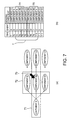
- FIG. 7 is an illustration of candidate events when a filter pattern is selected from the detection rules in accordance with certain embodiments.
- FIG. 8 is an illustration of candidate events when an ordered sequence pattern is selected from the detection rules in accordance with other embodiments.
- FIG. 9 is an illustration of candidate events when an unordered sequence pattern is selected from the detection rules in accordance with certain embodiments.
- FIG. 10 is an illustration of candidate events when a threshold pattern is selected from the detection rules in certain embodiments.
- FIG. 11 is a flowchart showing detection rule update processing by an apparatus in accordance with embodiments of the invention.
- FIG. 12 is a flowchart showing detection rule extracting processing by an apparatus in accordance with embodiments of the invention.
- FIG. 13 a flowchart showing detection rule extracting processing by an apparatus in accordance with embodiments of the invention.
- FIG. 14 illustrates a topology when the number of selected events is singular
- FIG. 15 illustrates a topology when the number of selected events is plural and the selected events are the same type
- FIG. 16 illustrates a topology when the number of selected events is plural and the selected events are different types
- FIG. 17 illustrates a topology when the number of selected events is plural, the relationship among components is uncorrelated, and the selected events are the same type
- FIG. 18 illustrates a topology when the number of selected events is plural, the relationship among components is uncorrelated, and the selected events are different types;
- FIG. 19 illustrates a topology when the number of selected events is plural, the relationship among components is parallel, and the selected events are of the same kind
- FIG. 20 illustrates a topology when the number of selected events is plural, the relationship among components is parallel, and the selected events are different types;
- FIG. 22 illustrates a topology when the number of selected events is plural, the relationship among components is not the perfect serial relationship, and the selected events are different types;
- FIG. 23 illustrates a topology when the number of selected events is plural, the relationship among components is a perfect serial relationship, and the selected events are the same kind;
- FIG. 24 illustrates a topology when the number of selected events is plural, the relationship among components is a perfect serial relationship, and the selected events are different types.
- embodiments of the invention may be embodied as an apparatus, method, or computer program product.
- the present invention may take the form of an entirely hardware embodiment, an entirely software embodiment (including firmware, resident software, micro-code, etc.) or an embodiment combining software and hardware elements.
- Hardware and/or software elements provided to perform various tasks may be generally referred to herein as “modules.”
- the present invention may take the form of a computer program product embodied in any tangible medium of expression having computer-usable program code embodied in the medium.
- the computer-usable or computer-readable medium may be, for example but not limited to, an electronic, magnetic, optical, electromagnetic, infrared, or semiconductor system, apparatus, device, or propagation medium.
- the computer-readable medium may include the following: an electrical connection having one or more wires, a portable computer diskette, a hard disk, a random access memory (“RAM”), a read-only memory (“ROM”), an erasable programmable read-only memory (“EPROM” or Flash memory), an optical fiber, a portable compact disc read-only memory (“CDROM”), an optical storage device, transmission media such as those supporting the Internet or an intranet, or a magnetic storage device.
- RAM random access memory
- ROM read-only memory
- EPROM erasable programmable read-only memory
- CDROM portable compact disc read-only memory
- CDROM compact disc read-only memory
- transmission media such as those supporting the Internet or an intranet, or a magnetic storage device.
- the computer-usable or computer-readable medium could even be paper or another suitable medium upon which the program is printed, as the program can be electronically captured, via, for instance, optical scanning of the paper or other medium, then compiled, interpreted, or otherwise processed in a suitable manner, if necessary, and then stored in a computer memory.
- a computer-usable or computer-readable medium may be any medium that can contain, store, communicate, propagate, or transport the program for use by or in connection with the instruction execution system, apparatus, or device.
- the computer-usable medium may include a propagated data signal with the computer-usable program code embodied therewith, either in baseband or as part of a carrier wave.
- the computer-usable program code may be transmitted using any appropriate medium, including but not limited to wireless, wireline, optical fiber cable, RF, etc.
- These computer program instructions may also be stored in a computer-readable medium that can direct a computer or other programmable data processing apparatus to function in a particular manner, such that the instructions stored in the computer-readable medium produce an article of manufacture including instruction means which implement the function/act specified in the flowchart and/or block diagram block or blocks.
- the computer program instructions may also be loaded onto a computer or other programmable data processing apparatus to cause a series of operational steps to be performed on the computer or other programmable apparatus to produce a computer implemented process such that the instructions which execute on the computer or other programmable apparatus provide processes for implementing the functions/acts specified in the flowchart and/or block diagram block or blocks.
- system configuration information refers broadly to information related to dependencies among multiple components that configure the system, as well as to information capable of deriving relations useful for failure analysis.
- System configuration information may include, for example, the relation of connection and communication, and the relation between subject and object of operations in accordance with commands or instructions.
- topology refers to a conceptual map showing connections and dependencies among components.
- system configuration information may include related information describing relationships among components, so that the detection rules can be generated to include not only the dependencies among components but also the related information. Further, candidate events may be presented based on the detection rules, thereby effectively supporting detection rule-generation work by a user, as well as reliably generating the detection rules of a certain level or higher without requiring the user to demonstrate a high level of skill in detection rule generation.
- FIG. 1 is a block diagram showing an exemplary detection rule-generating apparatus in accordance with an embodiment of the present invention.
- the detection rule-generating apparatus 1 may include a Central Processing Unit (“CPU”) 11 , a memory 12 , a storage device 13 , an I/O interface 14 , a communication interface 15 , a video interface 16 , a portable disk drive 17 , and an internal bus 18 for connecting the above-mentioned hardware components.
- CPU Central Processing Unit
- the storage device 13 may be configured as a built-in fixed storage device (hard disk), a ROM, or the like.
- the computer program 100 stored in the storage device 13 may be downloaded from a portable recording medium 90 , such as a DVD or CD-ROM, through the portable disk drive 17 .
- the portable recording medium 90 may store information, such as the program and data. This downloaded information may be loaded from the storage device 13 into the memory 12 at the time of execution.
- the computer program may be downloaded from an external computer connected to a network 2 through a communication interface 15 .
- the storage device 13 may include a symptom database 131 .
- a recommended action, a comment, or the like may be added to the symptom database 131 .
- a detection rule may be extracted according to the selected events. The detection rule may then be displayed on a display device 23 , together with a topology diagram of components.
- the storage device 13 may also include a configuration information storing section 132 for storing system configuration information of a system as a monitoring target to determine whether a failure has occurred, and a history information storing section 133 for storing history information, such as log information of the system, as the monitoring target and event information output when a failure has occurred.
- the configuration information storing section 132 may include a Change and Configuration Management Database (“CCMDB”) that includes dependency information and related information for components of a monitoring target system 200 .
- CCMDB Change and Configuration Management Database
- the topology diagram of components may be based on the system configuration information stored in the configuration information storing section 132 .
- the configuration information storing section 132 may be included in the storage device 13 , it may be provided separately from the detection rule-generating apparatus 1 , e.g., it may be provided by an external computer connected through the network 2 .
- the communication interface 15 may be connected to the internal bus 18 so that it can exchange data with the external computer via connection to an external network 2 such as the Internet, LAN, or WAN.
- the communication interface 15 may also be connected to the monitoring target system 200 through the network 2 , making it possible to acquire the system configuration information, history information, and the like at the time of a failure.
- FIG. 2 illustrates detection rule generation by a detection rule-generating apparatus in accordance with embodiments of the present invention.
- a configuration information-extracting section 201 may extract the system configuration information, including related information for components included in the monitoring target system 200 , and may store it in the configuration information-storing section 132 .
- the system configuration information may include, for example, relations between components in communication with one another, link-related information related to an operating/operated relationship, and the like.
- the system configuration information may be generated beforehand in the configuration information-storing section 132 , and the configuration information-extracting section 201 may be omitted.
- the configuration information-extracting section 201 and the configuration information-storing section 132 may not be indispensable to the detection rule-generating apparatus 1 in accordance with embodiments of the present invention.
- a configuration information-acquiring section 202 may acquire the system configuration information stored in the configuration information-storing section 132 .
- the system configuration information may be stored in the configuration information-storing section 132 associated with each monitoring target system 200 , and the configuration information-acquiring section 202 may acquire corresponding system configuration information according to the monitoring target system 200 .
- a history information-collecting section 203 may monitor the monitoring target system 200 at all times, collect history information such as output from each component included in the monitoring target system 200 and/or failure information such as event information output upon occurrence of a failure, and may store the history information in the history information-storing section 133 .
- the log information may not be limited to system logs output at all times, and may include message information output by interrupt processing or the like at the time of failure occurrence.
- history information collected in the history information-collecting section 203 often have different formats. As a result, such portions may not be used as-is for identifying candidate events. It may therefore be desirable to include a data format-converting section 209 to convert the portions of history information into a standard unified data format, and store them in the history information-storing section 133 .
- log information and/or failure information may be collected in a unified data format, thereby facilitating display and analysis of events included in the log information and/or failure information, and allowing candidate events to be identified more easily, as discussed in more detail below.
- a candidate event-identifying section 204 may identify candidate events based on the system configuration information acquired by the configuration information-acquiring section 202 and the history information stored in the history information-storing section 133 . Such candidate events may facilitate generating a detection rule for detecting an event causing a failure.
- a candidate event-presenting section 205 may present the identified candidate events on the display device 23 . This may allow a user to select an optimal event from the listed candidate events, thereby facilitating accuracy in generating a detection rule.
- a detection rule generating/storing section 206 may generate a detection rule based on system configuration information that includes the component from which the selected event has been sent. The detection rule may then be stored in the symptom database 131 .
- a candidate event-detecting section 207 may present, on the display device 23 through the candidate event-presenting section 205 , a next candidate event to be selected based on the generated detection rule and the stored history information. This may allow the user to select a more optimal event and generate the detection rule even more accurately.
- a detection rule-presenting section 208 may present, on the display device 23 , a detection rule that may be updated by selecting a candidate event, as discussed in more detail below.
- a detection rule may be updated by the detection rule-generating apparatus 1 in accordance with certain embodiments of the invention.
- An event selection-accepting section 301 may accept a user's selection of at least one event from an event list displayed on the display device 23 .
- the event may be selected using a pointing device, such as the mouse 22 , or by key input through the keyboard 21 .
- a detection rule-extracting section 302 may extract a detection rule according to a topology that includes one or more components corresponding to the accepted selected events.
- the extracted detection rule may be presented, by the detection rule-presenting section 208 , on part of a screen 40 of the display device 23 .
- An update section 303 may accept updates to the detection rule presented on the display device 23 , and may update the symptom database 131 .
- events included in the monitoring target system 200 may be listed.
- the event selection-accepting section 301 accepts the selection of candidate events from the events displayed in the event list-displaying area 43 .
- the candidate events that have been selected and accepted, and events having dependencies may be highlighted.
- the candidate events that have been accepted and an event having a dependency are indicated by a change in the display color, although such events may also be indicated by a change in brightness, or by any suitable method or means known to those in the art.
- the detection rules extracted by the detection rule-extracting section 302 may be displayed in the recommended information-displaying area 42 in order of priority. Then, if any of the displayed detection rules is selected using the pointing device, such as the mouse 22 , the topology diagram displayed in the topology diagram displaying area 41 may be changed.
- the recommended additional events may also be displayed in the recommended information-displaying area 42 . Therefore, when an additional event is selected through the update section 303 using the pointing device such as the mouse 22 , the additional event may be added to the topology diagram displayed in the topology diagram displaying area 41 such that the symptom database 131 may be updated.
- FIG. 5 illustrates typical rule patterns of the generated detection rules.
- FIG. 5( a ) illustrates a filter pattern
- FIG. 5( b ) illustrates a sequence pattern
- FIG. 5( c ) illustrates a threshold pattern, respectively.
- a filter pattern may provide a detection rule for checking whether an individual event matches each of the selected events. This may provide an effective detection rule when there is one selected and accepted event. As shown, event f has been selected as selected event ‘ 1 .’
- a sequence pattern may provide a detection rule for detecting the presence or absence of a sequence of events. This may provide an effective detection rule when there are multiple selected and accepted events. As shown, event ‘c’ corresponding to selected event ‘ 1 ,’ and event ‘e’ corresponding to selected event ‘ 2 ’ exist in this order among events existing within a certain fixed period T.
- a threshold pattern may provide a detection rule for comparing a certain numerical value with a threshold. This may provide an effective detection rule when there are multiple selected and accepted events. As shown, events ‘b,’ ‘d,’ ‘f,’ and ‘g’ corresponding to selected event ‘ 1 ,’ from among events ‘a’ to event ‘i,’ are counted. The events hatched in FIG. 5( c ) may be events corresponding to selected event ‘ 1 ’ within the certain fixed period T. Here, since the threshold is set to ‘four’ events, it may be confirmed that events are selected in a range equal to or greater than the threshold.
- FIG. 6 illustrates detection rule-generating processing by a detection rule-generating apparatus 1 in accordance with embodiments of the invention.
- the detection rule-generating apparatus 1 may acquire S 601 system configuration information, including related information for components included in the monitoring target system 200 .
- the system configuration information may be acquired beforehand and pre-stored in the configuration information-storing section 132 .
- the CPU 11 of the detection rule-generating apparatus 1 may monitor the monitoring target system 200 , collect S 602 history information and/or failure information, convert S 603 the data format to a standard unified data format, and store S 604 the history information in the history information-storing section 133 of the storage device 13 .
- the history information may include log information output from each component included in the monitoring target system 200 .
- the failure information may include event information output upon occurrence of a failure.
- the log information is not limited to system logs output, and may include message information output by interrupt processing at the time of a failure occurrence.
- the CPU 11 may identify S 605 candidate events based on the system configuration information stored in the configuration information-storing section 132 and the history information stored in the history information-storing section 133 . Either or both of the configuration information-storing section 132 and the history information-storing section 133 may be included in the storage device 13 . Then, the CPU 11 may output and display S 606 the identified candidate events on the display device 23 .
- This method of identifying the candidate events based on the system configuration information and the history information is not particularly limited. For simplicity, however, the procedure of identifying candidate events is described below with reference to the rule patterns of FIG. 5 .
- the sequence pattern may be further classified into two kinds of rule patterns.
- An ordered sequence pattern may have an identified order
- an unordered sequence pattern may have an order that is not identified.
- FIGS. 7( a ) and 7 ( b ) illustrate exemplary candidate events when a filter pattern is selected from the detection rules. Particularly, FIG. 7( a ) illustrates a topology diagram displayed in the topology diagram displaying area 41 . FIG. 7( b ) illustrates events displayed in the event list displaying area 43 .
- a selected event is component B 2 (indicated by arrow 73 )
- corresponding event B may also be selected and accepted in the event list-displaying area 43 .
- selected event B is indicated by highlighting or hatching.
- components A and C 2 may be selected as close components 71 that are close to and have dependencies with the component B 2 . Therefore, events existing within the certain fixed period T and corresponding to the selected components A and C 2 may become candidate events. Further, components B 1 , B 2 , and B 3 may be selected as the same kind of components 72 that are in a parallel relationship with the component B 2 . Therefore, events existing within the certain fixed period T and corresponding to the selected components B 1 , B 2 , and B 3 may also be candidate events. Thus, as shown in FIG. 7( b ), events C, D, E, D′, I, and C′ may be identified as candidate events corresponding to sending component groups 74 and 75 .
- FIG. 8 illustrates exemplary candidate events when the ordered sequence pattern is selected from the detection rules. Specifically, FIG. 8( a ) illustrates a topology diagram displayed in the topology diagram-displaying area 41 . FIG. 8( b ) illustrates events displayed in the event list-displaying area 43 .
- corresponding events C′ (the selection of which has been accepted through the component A) and D′ (the selection of which has been accepted through the component B 1 ) may be highlighted in the event list-displaying area 43 .
- both selected and accepted events may be indicated by hatching.
- components A, B 1 , and C 1 may be selected as component group 81 having a serial relationship with the components A and B 1 . Therefore, events existing within the certain fixed period T and corresponding to the selected components A, B 1 , and C 1 may be candidate events. Thus, events E, A′, K, and E may be identified as candidate events corresponding to sending component groups 83 and 84 , as shown in FIG. 8( b ).
- FIG. 9 illustrates exemplary candidate events when an unordered sequence pattern is selected from the detection rules. Specifically, FIG. 9( a ) illustrates a topology diagram displayed in the topology diagram-displaying area 41 . FIG. 9( b ) illustrates events displayed in the event list-displaying area 43 .
- event A′ the selection of which has been accepted through the component A
- event D′ the selection of which has been accepted through the component B 1
- event B the selection of which has been accepted through the component B 2
- event C′ the selection of which has been accepted through the component C 2
- the event group may be indicated by hatching.
- components A, B 1 , B 2 , B 3 , C 1 , and C 2 may be selected as a component group 91 having a serial or partially serial relationship with components A, B 1 , B 2 , and C 2 . Therefore, events existing within the certain fixed period T and corresponding to the selected components A, B 1 , B 2 , B 3 , C 1 , and C 2 may be candidate events. Thus, events D, I, and K may also be identified as candidate events corresponding to sending components 93 , 94 , and 95 , as shown in FIG. 9( b ).
- FIG. 10 illustrates exemplary candidate events when a threshold pattern is selected from the detection rules. Specifically, FIG. 10( a ) illustrates a topology diagram displayed in the topology diagram-displaying area 41 . FIG. 10( b ) illustrates events displayed in the event list-displaying area 43 .
- event B the selection of which has been accepted through the component C 2
- event I the selection of which has been accepted through the component C 3
- the selected and accepted events are indicated by hatching.
- components C 1 , C 2 , and C 3 may be selected as component group 101 having a parallel relationship with components C 2 and C 3 . Therefore, events existing within the certain fixed period T and corresponding to the selected components C 1 , C 2 , and C 3 may be candidate events. Events E, K, and E may be identified as candidate events corresponding to sending components 103 , 104 , and 105 as shown in FIG. 10( b ).
- FIG. 11 illustrates a procedure for detection rule update processing by a detection rule-generating apparatus 1 in accordance with embodiments of the present invention.
- the CPU 11 of the detection rule-generating apparatus 1 may accept S 1101 a user's event selection.
- the user's event selection may be made using a pointing device such as the mouse 22 , or by key input through the keyboard 21 .
- the CPU 11 may extract SI 102 a detection rule according to a topology including one or more components corresponding to the event or events that have been selected and accepted.
- the CPU 11 may display S 1103 the extracted detection rule on the display device 23 .
- the updated detection rule may then be accepted S 1104 , and the symptom database 131 may be updated S 1105 .
- detection rules may be easily updated according to the acceptance of selected events in this manner, detection rules may be generated that are more adapted to actual system configuration.
- FIGS. 12 and 13 illustrate a procedure of detection rule-extraction processing by a detection rule-generating apparatus 1 in accordance with embodiments of the present invention.
- the CPU 11 of the detection rule-generating apparatus 1 may determine S 1201 whether there are multiple selected and accepted events. If not, the CPU 11 may give priority to extraction of the filter pattern S 1202 . It is, of course, understood that the threshold pattern may be extracted in some embodiments.
- FIGS. 14( a ) and 14 ( b ) illustrate a topology when the number of selected events is singular. Specifically, FIG. 14( a ) illustrates an event including the event occurrence time. FIG. 14( b ) illustrates a topology diagram including the event occurrence time.
- the CPU 11 of the detection rule-generating apparatus 1 may determine S 1203 whether the number of components from which multiple selected events have been sent out is more than one. If not, the CPU 11 may utilize an event determination section, for example, to determine S 1204 whether the selected events are the same kind or type. If yes, the CPU 11 may give priority to extraction of the threshold pattern as the detection rule S 1205 . It is, of course, understood that the filter pattern may be extracted in some embodiments.
- FIGS. 15( a ) and 15 ( b ) illustrate a topology when the number of selected events is plural and the selected events are the same kind. Specifically, FIG. 15( a ) illustrates events including the event occurrence times. FIG. 15( b ) illustrates a topology diagram including the event occurrence times.
- the CPU 11 of the detection rule-generating apparatus 1 may extract S 1206 a sequence pattern as the detection rule.
- the ordered sequence pattern or the unordered sequence pattern may be extracted on a priority basis according to the presence or absence of ordering of selected events. However, since the selected events are different from each other, extraction of the ordered sequence pattern may be given priority.
- FIGS. 16( a ) and 16 ( b ) illustrate a topology when there are multiple selected events and the selected events are different kinds or types. Specifically, FIG. 16( a ) illustrates events including the event occurrence times. FIG. 16( b ) illustrates a topology diagram including the event occurrence times.
- the detection rule that considers the order of occurrence of events may be extracted. Therefore, a sequence pattern may be extracted as the detection rule.
- the CPU 11 of the detection rule-generating apparatus 1 may utilize a connection determination section, for example, to determine S 1207 whether the components are connected in a topology. If not, the CPU 11 may utilize a parallel relationship-determining section, for example, to determine S 1208 whether the relation between components is parallel.
- the CPU 11 may then utilize an event determination section, for example, to determine whether the selected events are the same kind or type. If yes, the CPU 11 may extract S 1210 the unordered sequence pattern as the detection rule. It is, of course, understood that the threshold pattern may be extracted or the ordered sequence pattern may be extracted in certain embodiments.
- FIGS. 17( a ) and 17 ( b ) illustrate a topology when the number of selected events is plural, the relationship among components is uncorrelated, and the selected events are of the same kind or type.
- FIG. 17( a ) illustrates events including the event occurrence times.
- FIG. 17( b ) illustrates a topology diagram including the event occurrence times.
- the CPU 11 of the detection rule-generating apparatus 1 may extract S 1211 a sequence pattern as the detection rule.
- either the ordered sequence pattern or the unordered sequence pattern may be extracted on a priority basis, according to the presence or absence of ordering of selected events.
- the unordered sequence pattern may be extracted.
- FIGS. 18( a ) and 18 ( b ) illustrate a topology when there are multiple selected events, the relationship among components is uncorrelated, and the selected events are different.
- FIG. 18( a ) illustrates events including the event occurrence times.
- FIG. 18( b ) illustrates a topology diagram including the event occurrence times.
- the CPU 11 of the detection rule-generating apparatus 1 may determine S 1212 whether the selected events are the same kind or type. If yes, the CPU 11 may extract S 1213 the threshold pattern as the detection rule. It is, of course, understood that an unordered sequence pattern or an ordered sequence pattern may be extracted in certain embodiments.
- FIGS. 19( a ) and 19 ( b ) illustrate a topology when the number of selected events is plural, the relationship among components is the parallel relationship, and the selected events are the same kind.
- FIG. 19( a ) illustrates events including the event occurrence times.
- FIG. 19( b ) illustrates a topology diagram including the event occurrence times.
- the CPU 11 of the detection rule-generating apparatus 1 may extract S 1214 an unordered sequence pattern as the detection rule. It is, of course, understood that the threshold pattern or the ordered sequence pattern may be extracted in certain embodiments.
- FIGS. 20( a ) and 20 ( b ) illustrate a topology when the number of selected events is plural, the relationship among components is parallel, and the selected events are different kinds or types.
- FIG. 20( a ) illustrates events including the event occurrence times.
- FIG. 20( b ) illustrates a topology diagram including the event occurrence times.
- the CPU 11 of the detection rule-generating apparatus 1 may then utilize a serial relationship-determining section, for example, to determine S 1301 whether the components are in a perfect serial relationship as shown in FIG. 13 . If it is determined that the components are not in the perfect serial relationship, the CPU 11 may then determine whether the selected events are the same kind or type.
- the CPU 11 may extract S 1303 the ordered sequence pattern as the detection rule. It is, of course, understood that the threshold pattern or the unordered sequence pattern may be extracted in certain embodiments.
- FIGS. 21( a ) and 21 ( b ) illustrates a topology when the number of selected events is plural, the relationship among components is not a perfect serial relationship, and the selected events are of the same kind or type. Specifically, FIG. 21 ( a ) illustrates events including the event occurrence times. FIG. 21( b ) illustrates a topology diagram including the event occurrence times.
- the CPU 11 of the detection rule-generating apparatus 1 may extract S 1304 a sequence pattern as the detection rule.
- either the ordered sequence pattern or the unordered sequence pattern may be extracted on a priority basis according to the presence or absence of ordering of selected events.
- the unordered sequence pattern may be extracted.
- FIGS. 22( a ) and 22 ( b ) illustrate a topology when the number of selected events is plural, the relationship among components is not a perfect serial relationship, and the selected events are different kinds. Specifically, FIG. 22( a ) illustrates events including the event occurrence times. FIG. 22( b ) illustrates a topology diagram including the event occurrence times.
- the CPU 11 of the detection rule-generating apparatus 1 may then determine whether the selected events are the same kind. If yes, the CPU 11 may extract S 1306 the ordered sequence pattern as the detection rule. It is, of course, understood that the threshold pattern or the unordered sequence pattern may be extracted in certain embodiments.
- FIGS. 23( a ) and 23 ( b ) illustrate a topology when the number of selected events is plural, the relationship among components is a perfect serial relationship, and the selected events are the same kind. Specifically, FIG. 23( a ) illustrates events including the event occurrence times. FIG. 23( b ) illustrates a topology diagram including the event occurrence times.
- event A from components A, B, and C in the serial relationship
- event B occurred at 10:10, 10:20, and 10:30, respectively
- the ordered sequence pattern may be extracted as the detection rule.
- the CPU 11 of the detection rule-generating apparatus 1 may extract S 1307 a sequence pattern as the detection rule.
- either the ordered sequence pattern or the unordered sequence pattern may be extracted on a priority basis according to the presence or absence of ordering of selected events.
- the ordered sequence pattern may be extracted.
- FIGS. 24( a ) and 24 ( b ) illustrate a topology when the number of selected events is plural, the relationship among components is a perfect serial relationship, and the selected events are different kinds. Specifically, FIG. 24( a ) illustrates events including the event occurrence times. FIG. 24( b ) illustrates a topology diagram including the event occurrence times.
- the detection rules for events causing failures may be generated to include not only the dependencies among components, but also the related information. Further, candidate events may be presented based on the detection rules to effectively support detection rule-generation work by a user, as well as to enable reliable generation of high-level detection rules without requiring a high degree of skill from the user.
- the present invention is not limited to the aforementioned embodiment, and various changes and modifications are possible within the scope of the present invention.
- the symptom database, the configuration information-storing section, and the history information-storing section may be included in the storage device of an external computer connected through a network to the detection rule-generating apparatus and read as necessary.
Landscapes
- Engineering & Computer Science (AREA)
- Theoretical Computer Science (AREA)
- General Engineering & Computer Science (AREA)
- Software Systems (AREA)
- Physics & Mathematics (AREA)
- General Physics & Mathematics (AREA)
- Mathematical Physics (AREA)
- Computing Systems (AREA)
- Data Mining & Analysis (AREA)
- Evolutionary Computation (AREA)
- Computational Linguistics (AREA)
- Artificial Intelligence (AREA)
- Quality & Reliability (AREA)
- Multimedia (AREA)
- Debugging And Monitoring (AREA)
- Information Retrieval, Db Structures And Fs Structures Therefor (AREA)
Applications Claiming Priority (2)
| Application Number | Priority Date | Filing Date | Title |
|---|---|---|---|
| JP2008221142 | 2008-08-29 | ||
| JP2008-221142 | 2008-08-29 |
Publications (2)
| Publication Number | Publication Date |
|---|---|
| US20100057667A1 US20100057667A1 (en) | 2010-03-04 |
| US8612372B2 true US8612372B2 (en) | 2013-12-17 |
Family
ID=41721302
Family Applications (1)
| Application Number | Title | Priority Date | Filing Date |
|---|---|---|---|
| US12/479,058 Expired - Fee Related US8612372B2 (en) | 2008-08-29 | 2009-06-05 | Detection rule-generating facility |
Country Status (6)
| Country | Link |
|---|---|
| US (1) | US8612372B2 (de) |
| EP (1) | EP2336889A4 (de) |
| JP (1) | JP5274565B2 (de) |
| KR (1) | KR20110048522A (de) |
| CN (1) | CN102138130A (de) |
| WO (1) | WO2010024133A1 (de) |
Cited By (2)
| Publication number | Priority date | Publication date | Assignee | Title |
|---|---|---|---|---|
| US20130339810A1 (en) * | 2010-12-13 | 2013-12-19 | Hitachi, Ltd. | Design Support System |
| US10572332B1 (en) * | 2017-10-30 | 2020-02-25 | Wells Fargo Bank, N.A. | Failure prediction system |
Families Citing this family (20)
| Publication number | Priority date | Publication date | Assignee | Title |
|---|---|---|---|---|
| JP5220556B2 (ja) * | 2008-10-30 | 2013-06-26 | インターナショナル・ビジネス・マシーンズ・コーポレーション | 障害イベントの検出を支援する装置、障害イベントの検出を支援する方法及びコンピュータプログラム |
| JP5258040B2 (ja) * | 2008-10-30 | 2013-08-07 | インターナショナル・ビジネス・マシーンズ・コーポレーション | 障害イベントの検出を支援する装置、障害イベントの検出を支援する方法及びコンピュータプログラム |
| JP5220555B2 (ja) * | 2008-10-30 | 2013-06-26 | インターナショナル・ビジネス・マシーンズ・コーポレーション | 障害イベントの検出を支援する装置、障害イベントの検出を支援する方法及びコンピュータプログラム |
| US9142965B2 (en) | 2011-07-28 | 2015-09-22 | Tigo Energy, Inc. | Systems and methods to combine strings of solar panels |
| US8793538B2 (en) | 2012-01-30 | 2014-07-29 | Hewlett-Packard Development Company, L.P. | System error response |
| JP6048038B2 (ja) * | 2012-09-27 | 2016-12-21 | 富士通株式会社 | 情報処理装置,プログラム,情報処理方法 |
| CN103888304B (zh) * | 2012-12-19 | 2017-08-04 | 华为技术有限公司 | 一种多节点应用的异常检测方法及相关装置 |
| US9088541B2 (en) | 2013-05-31 | 2015-07-21 | Catbird Networks, Inc. | Systems and methods for dynamic network security control and configuration |
| US9912549B2 (en) | 2013-06-14 | 2018-03-06 | Catbird Networks, Inc. | Systems and methods for network analysis and reporting |
| US11196636B2 (en) | 2013-06-14 | 2021-12-07 | Catbird Networks, Inc. | Systems and methods for network data flow aggregation |
| WO2015059791A1 (ja) * | 2013-10-24 | 2015-04-30 | 三菱電機株式会社 | 情報処理装置及び情報処理方法及びプログラム |
| JP6244992B2 (ja) | 2014-03-07 | 2017-12-13 | 富士通株式会社 | 構成情報管理プログラム、構成情報管理方法、及び構成情報管理装置 |
| US9965547B2 (en) | 2014-05-09 | 2018-05-08 | Camelot Uk Bidco Limited | System and methods for automating trademark and service mark searches |
| US11100124B2 (en) | 2014-05-09 | 2021-08-24 | Camelot Uk Bidco Limited | Systems and methods for similarity and context measures for trademark and service mark analysis and repository searches |
| US10565533B2 (en) | 2014-05-09 | 2020-02-18 | Camelot Uk Bidco Limited | Systems and methods for similarity and context measures for trademark and service mark analysis and repository searches |
| RU2679179C1 (ru) | 2014-09-05 | 2019-02-06 | Кэтбёрд Нэтворкс, Инк. | Системы и способы для создания и модификации списков управления доступом |
| JP6564305B2 (ja) * | 2015-10-30 | 2019-08-21 | 株式会社日立システムズ | 管理サーバ及びこれを用いた管理方法 |
| US10205736B2 (en) * | 2017-02-27 | 2019-02-12 | Catbird Networks, Inc. | Behavioral baselining of network systems |
| US11681710B2 (en) * | 2018-12-23 | 2023-06-20 | Microsoft Technology Licensing, Llc | Entity extraction rules harvesting and performance |
| US20210133622A1 (en) * | 2019-10-31 | 2021-05-06 | International Business Machines Corporation | Ml-based event handling |
Citations (9)
| Publication number | Priority date | Publication date | Assignee | Title |
|---|---|---|---|---|
| JP2001005692A (ja) | 1999-06-25 | 2001-01-12 | Toshiba Corp | 計算機システムおよびその保守管理システム並びに障害通知方法 |
| US20050086538A1 (en) * | 2002-05-28 | 2005-04-21 | Fujitsu Limited | Method and apparatus for detecting unauthorized-access, and computer product |
| JP2005316728A (ja) | 2004-04-28 | 2005-11-10 | Mitsubishi Electric Corp | 障害解析装置、障害解析方法及び障害解析プログラム |
| JP2007257184A (ja) | 2006-03-22 | 2007-10-04 | Nec Corp | 障害原因推定システム、方法、及び、プログラム |
| JP2008033725A (ja) | 2006-07-31 | 2008-02-14 | Nec Corp | 運用管理システム、監視装置、監視設定情報生成方法及びプログラム |
| JP2008041041A (ja) | 2006-08-10 | 2008-02-21 | Hitachi Information Systems Ltd | ログ通知条件定義支援装置とログ監視システムおよびプログラムとログ通知条件定義支援方法 |
| JP2008065688A (ja) | 2006-09-08 | 2008-03-21 | Toshiba Corp | 医療検査情報統合システム |
| US7433855B2 (en) * | 1995-04-21 | 2008-10-07 | Mci Communications Corporation | System and method for detecting and managing fraud |
| JP2008292902A (ja) | 2007-05-28 | 2008-12-04 | Canon Inc | 像振れ補正装置および撮像装置 |
Family Cites Families (5)
| Publication number | Priority date | Publication date | Assignee | Title |
|---|---|---|---|---|
| JPH0877010A (ja) * | 1994-09-07 | 1996-03-22 | Hitachi Ltd | データ分析方法および装置 |
| JPH08292902A (ja) * | 1995-04-20 | 1996-11-05 | Fuji Xerox Co Ltd | 情報処理装置 |
| JP4746850B2 (ja) * | 2004-06-21 | 2011-08-10 | 富士通株式会社 | パターン生成プログラム |
| JP2006031109A (ja) * | 2004-07-12 | 2006-02-02 | Ntt Docomo Inc | 管理システム及び管理方法 |
| JP2007172131A (ja) * | 2005-12-20 | 2007-07-05 | Nec Fielding Ltd | 障害予測システム、障害予測方法、障害予測プログラム |
-
2009
- 2009-06-05 US US12/479,058 patent/US8612372B2/en not_active Expired - Fee Related
- 2009-08-13 EP EP09809786.8A patent/EP2336889A4/de not_active Withdrawn
- 2009-08-13 WO PCT/JP2009/064308 patent/WO2010024133A1/ja not_active Ceased
- 2009-08-13 KR KR1020117003458A patent/KR20110048522A/ko not_active Ceased
- 2009-08-13 JP JP2010526651A patent/JP5274565B2/ja not_active Expired - Fee Related
- 2009-08-13 CN CN2009801340436A patent/CN102138130A/zh active Pending
Patent Citations (9)
| Publication number | Priority date | Publication date | Assignee | Title |
|---|---|---|---|---|
| US7433855B2 (en) * | 1995-04-21 | 2008-10-07 | Mci Communications Corporation | System and method for detecting and managing fraud |
| JP2001005692A (ja) | 1999-06-25 | 2001-01-12 | Toshiba Corp | 計算機システムおよびその保守管理システム並びに障害通知方法 |
| US20050086538A1 (en) * | 2002-05-28 | 2005-04-21 | Fujitsu Limited | Method and apparatus for detecting unauthorized-access, and computer product |
| JP2005316728A (ja) | 2004-04-28 | 2005-11-10 | Mitsubishi Electric Corp | 障害解析装置、障害解析方法及び障害解析プログラム |
| JP2007257184A (ja) | 2006-03-22 | 2007-10-04 | Nec Corp | 障害原因推定システム、方法、及び、プログラム |
| JP2008033725A (ja) | 2006-07-31 | 2008-02-14 | Nec Corp | 運用管理システム、監視装置、監視設定情報生成方法及びプログラム |
| JP2008041041A (ja) | 2006-08-10 | 2008-02-21 | Hitachi Information Systems Ltd | ログ通知条件定義支援装置とログ監視システムおよびプログラムとログ通知条件定義支援方法 |
| JP2008065688A (ja) | 2006-09-08 | 2008-03-21 | Toshiba Corp | 医療検査情報統合システム |
| JP2008292902A (ja) | 2007-05-28 | 2008-12-04 | Canon Inc | 像振れ補正装置および撮像装置 |
Non-Patent Citations (2)
| Title |
|---|
| Gujrati et al., A Meta-Learning Failure Predictor for Blue Gene/L Systems [online], 2007 [retrieved on Jan. 24, 2012]. Retrieved from the Internet:. * |
| Gujrati et al., A Meta-Learning Failure Predictor for Blue Gene/L Systems [online], 2007 [retrieved on Jan. 24, 2012]. Retrieved from the Internet:< URL: http://ieeexplore.ieee.org/xpls/abs—all.jsp?arnumber=4343847&tag=1>. * |
Cited By (4)
| Publication number | Priority date | Publication date | Assignee | Title |
|---|---|---|---|---|
| US20130339810A1 (en) * | 2010-12-13 | 2013-12-19 | Hitachi, Ltd. | Design Support System |
| US9146827B2 (en) * | 2010-12-13 | 2015-09-29 | Hitachi, Ltd. | Support system |
| US10572332B1 (en) * | 2017-10-30 | 2020-02-25 | Wells Fargo Bank, N.A. | Failure prediction system |
| US11231984B1 (en) | 2017-10-30 | 2022-01-25 | Wells Fargo Bank, N.A. | Failure prediction system |
Also Published As
| Publication number | Publication date |
|---|---|
| US20100057667A1 (en) | 2010-03-04 |
| JP5274565B2 (ja) | 2013-08-28 |
| KR20110048522A (ko) | 2011-05-11 |
| CN102138130A (zh) | 2011-07-27 |
| EP2336889A1 (de) | 2011-06-22 |
| EP2336889A4 (de) | 2016-07-27 |
| JPWO2010024133A1 (ja) | 2012-01-26 |
| WO2010024133A1 (ja) | 2010-03-04 |
Similar Documents
| Publication | Publication Date | Title |
|---|---|---|
| US20100057667A1 (en) | Detection rule-generating facility | |
| CN110928772B (zh) | 一种测试方法及装置 | |
| US7721158B2 (en) | Customization conflict detection and resolution | |
| JP5285084B2 (ja) | 検出イベントに応じたアクション実行を支援するシステム、検出イベントに応じたアクション実行を支援する方法、支援装置及びコンピュータプログラム | |
| US8762777B2 (en) | Supporting detection of failure event | |
| JP6919569B2 (ja) | ログ分析システム、方法、及び記録媒体 | |
| JP2018045403A (ja) | 異常検知システム及び異常検知方法 | |
| US20120143947A1 (en) | Method, apparatus, and program for usability analysis of web applications | |
| US10817140B2 (en) | Sequential data | |
| JP4458493B2 (ja) | ログ通知条件定義支援装置とログ監視システムおよびプログラムとログ通知条件定義支援方法 | |
| WO2018069950A1 (ja) | ログ分析方法、システムおよびプログラム | |
| JP2008134705A (ja) | データ処理方法及びデータ分析装置 | |
| CN119322733B (zh) | 基于人工智能的代码分析方法、装置、设备、存储介质 | |
| JP2017049639A (ja) | 評価プログラム、手順書評価方法、および評価装置 | |
| CN119829030A (zh) | 基于交互式模型的代码分析方法及其装置、电子设备 | |
| US20070299705A1 (en) | Method and apparatus for observation model validation | |
| US20150277858A1 (en) | Performance evaluation device, method, and medium for information system | |
| CN103605777A (zh) | 数据库索引处理方法和装置 | |
| JP6447111B2 (ja) | 共通化情報提供プログラム、共通化情報提供方法、および共通化情報提供装置 | |
| US9372746B2 (en) | Methods for identifying silent failures in an application and devices thereof | |
| JP2022140929A (ja) | 情報処理プログラム、情報処理方法、および情報処理装置 | |
| JP5197128B2 (ja) | 依存関係推定装置及び依存関係推定プログラム及び記録媒体 | |
| JPWO2019012572A1 (ja) | データリニエージ検出装置、データリニエージ検出方法、及びデータリニエージ検出プログラム | |
| JP4810113B2 (ja) | データベースチューニング装置及びデータベースチューニング方法並びにプログラム | |
| JP4663526B2 (ja) | 帳票作成支援装置、帳票作成支援方法、および帳票作成支援プログラム |
Legal Events
| Date | Code | Title | Description |
|---|---|---|---|
| AS | Assignment |
Owner name: INTERNATIONAL BUSINESS MACHINES CORPORATION,NEW YO Free format text: ASSIGNMENT OF ASSIGNORS INTEREST;ASSIGNORS:GOTOH, YASUHISA;KANEYASU, YUHSUKE;SIGNING DATES FROM 20090525 TO 20090527;REEL/FRAME:022788/0050 Owner name: INTERNATIONAL BUSINESS MACHINES CORPORATION, NEW Y Free format text: ASSIGNMENT OF ASSIGNORS INTEREST;ASSIGNORS:GOTOH, YASUHISA;KANEYASU, YUHSUKE;SIGNING DATES FROM 20090525 TO 20090527;REEL/FRAME:022788/0050 |
|
| REMI | Maintenance fee reminder mailed | ||
| LAPS | Lapse for failure to pay maintenance fees |
Free format text: PATENT EXPIRED FOR FAILURE TO PAY MAINTENANCE FEES (ORIGINAL EVENT CODE: EXP.) |
|
| STCH | Information on status: patent discontinuation |
Free format text: PATENT EXPIRED DUE TO NONPAYMENT OF MAINTENANCE FEES UNDER 37 CFR 1.362 |
|
| STCH | Information on status: patent discontinuation |
Free format text: PATENT EXPIRED DUE TO NONPAYMENT OF MAINTENANCE FEES UNDER 37 CFR 1.362 |
|
| FP | Lapsed due to failure to pay maintenance fee |
Effective date: 20171217 |