US8702828B2 - Flat bag for vacuum cleaners - Google Patents
Flat bag for vacuum cleaners Download PDFInfo
- Publication number
- US8702828B2 US8702828B2 US13/377,668 US201013377668A US8702828B2 US 8702828 B2 US8702828 B2 US 8702828B2 US 201013377668 A US201013377668 A US 201013377668A US 8702828 B2 US8702828 B2 US 8702828B2
- Authority
- US
- United States
- Prior art keywords
- flat bag
- bag
- diffuser
- bag according
- flat
- Prior art date
- Legal status (The legal status is an assumption and is not a legal conclusion. Google has not performed a legal analysis and makes no representation as to the accuracy of the status listed.)
- Active, expires
Links
Images


Classifications
-
- A—HUMAN NECESSITIES
- A47—FURNITURE; DOMESTIC ARTICLES OR APPLIANCES; COFFEE MILLS; SPICE MILLS; SUCTION CLEANERS IN GENERAL
- A47L—DOMESTIC WASHING OR CLEANING; SUCTION CLEANERS IN GENERAL
- A47L9/00—Details or accessories of suction cleaners, e.g. mechanical means for controlling the suction or for effecting pulsating action; Storing devices specially adapted to suction cleaners or parts thereof; Carrying-vehicles specially adapted for suction cleaners
- A47L9/10—Filters; Dust separators; Dust removal; Automatic exchange of filters
- A47L9/102—Dust separators
-
- A—HUMAN NECESSITIES
- A47—FURNITURE; DOMESTIC ARTICLES OR APPLIANCES; COFFEE MILLS; SPICE MILLS; SUCTION CLEANERS IN GENERAL
- A47L—DOMESTIC WASHING OR CLEANING; SUCTION CLEANERS IN GENERAL
- A47L9/00—Details or accessories of suction cleaners, e.g. mechanical means for controlling the suction or for effecting pulsating action; Storing devices specially adapted to suction cleaners or parts thereof; Carrying-vehicles specially adapted for suction cleaners
- A47L9/10—Filters; Dust separators; Dust removal; Automatic exchange of filters
- A47L9/14—Bags or the like; Rigid filtering receptacles; Attachment of, or closures for, bags or receptacles
Definitions
- the present invention relates to a flat bag for vacuum cleaners, which has, in the interior thereof, at least one diffuser which forms an intermediate plane and is made of strips of material and/or sheet materials with oblong-shaped flow openings, Such flat bags are distinguished by excellent dust storage capacity and extension of the useful life.
- EP 0 960 645 and EP 1 795 247 disclose nonwoven materials for vacuum cleaner bags having particularly good dust storage capacity.
- EP 1 787 560 shows flow distributors in the form of squares or strips of material which are fitted in the region of the inlet opening of the filter bag and are able to split and deflect the incoming airflow into partial flows.
- EP 1 804 635 the concept is developed with respect to a second flow distributor supplementing the function of the first flow distributor. From DE 20 2008 008 989 and DE 20 2008 003 248, combinations of two flow distributors with a spacing means are known.
- a filter bag which comprises a bag having an interior which is subdivided into at least two chambers.
- the subdivision is effected by a separating wall which is fixed at three side edges, a transition between the first and the second chamber being formed at the fourth side edge.
- the separating wall is welded to the filter layers only at one side edge for the entire length and is welded on the opposite side to a strip on the upper layer made of filter material.
- DE 20 2008 007 717 describes a filter bag in which a planar, multilayer filter insert which is connected at least partially to the filter bag walls is disposed in the interior. Dust is intended thereby to be incorporated between the at least two layers of the filter insert.
- the upper of the two layers can be perforated or slotted.
- the filter insert can be configured as a continuous strip which is fixed at two oppositely situated edges of the bag.
- DE 20 2007 010 692 relates to a filter bag in which a filler layer made of fibre- or yarn material extends between the two filter walls, which layer is connected to both filter walls and, when the bag is unfolded, is pulled apart such that a net-like structure is produced in the bag.
- a dust filter bag having a blocking wall part fitted in the interior is known from DE 20 2006 019 108.
- This blocking wall part is mounted in front of the inlet opening of the bag such that it bulges out during operation and forms two outlet openings through which the airflow is deflected. It is essential to the invention that the blocking wall part is mounted at a spacing relative to the bag seam and does not abut against the rear bag wall under the pressure of the airflow.
- a further air distributor is known from DE 10 2006 051 117. At least two material layers are thereby disposed one above the other between the bag walls, the layers having less extension in a first surface direction than the two bag walls and, in the surface direction orthogonal to the first surface direction, having the same extension as the bag walls. There may be mentioned as materials, microfibre nonwoven or paper.
- DE 2006 016 304 discloses a bag having at least one guide element, by means of which the incoming airflow can be deflected.
- the guide element is fixed adjacent to the inflow opening.
- a bag already found on the market of the company Miele has an arrangement of a deflection device which is fitted directly below the inlet opening.
- This deflection device consists of a sheet material which is fitted directly with the upper side of the bag on both sides of the inlet opening.
- the purpose of this deflection device resides in deflecting the airflow which is suctioned in through the inlet opening directly in the region of the inlet opening.
- This deflection device is configured such that it is welded directly to the bag wall at a spacing relative to the inlet opening on the basis of a prescribed length or area. The area of this deflection device is therefore below approx. 10% of the bag surface.
- This filter bag is sketched in FIG. 3 .
- this vacuum cleaner bag also has a second plane of flow directors.
- the present invention relates to a vacuum cleaner filter bag which ensures increased dust storage capacity and hence an extension of the useful life (lifespan). In addition, blockage of the inlet opening in the interior of the bag is intended to be prevented.
- a flat bag having a bag upper side and a bag underside
- at least one diffuser which forms an intermediate plane is disposed in the interior of the flat bag between the bag upper side and the bag underside and consists of at least two individual strips of material and/or sheet materials, disposed next to each other, which have oblong-shaped flow openings, the at least one diffuser being connected to the bag wall at least on one side.
- the diffusers which are formed from strips of material or sheet materials provided with flow openings thereby cause turbulence of the inflowing air which is laden with dirt and/or dust particles. Hence the lifespan of the bag can surprisingly be substantially extended.
- the flat bags according to the present invention include at least one diffuser in an intermediate plane for turbulence of the suctioned-in dust particles.
- this intermediate plane a curved or uncurved surface which is disposed between the bag upper side and underside forming the bag wall.
- the intermediate plane in the sense of the invention is hence defined by the arrangement of the diffuser in the interior of the filter bag by connecting the diffuser at at least 1 point of the bag wall.
- the diffuser made of a floppy material is thereby formed either from at least two strips of material, disposed next to each other, but can also consist of sheet materials which have flow openings in the sense of slots within these sheet materials.
- Such sheet materials hence have at least one slot or a cut which however is not impressed continuously over the entire sheet material so that, at the ends of the sheet material, i.e. wherever there is no slotting, cohesion of the sheet material is ensured.
- the geometric shape of the strips of material or the geometric shapes formed by the flow openings on the sheet material is thereby essentially irrelevant; thus the strips of material can for example be structured as strips or the sheet materials by straight slots, however likewise all other possible geometric shapes of strips of material or sheet materials are possible, for example also s-shaped strips or slot guides, but also through-openings etc.
- the diffuser in the form of sheet materials with oblong-shaped flow openings is disposed in the first plane directly below the filter bag upper side in the region of the inlet opening, this diffuser being mounted on the bag upper side on both sides and the area thereof being less than 10%, relative to the total bag surface, the width of the strips of material defined by the slots, relative to the diameter of the inflow opening, being defined at ⁇ 50%.
- the diffuser is therefore shorter than the total length or width of the flat bag. Both ends of the diffuser configured as a slotted sheet material are fixed directly on the bag upper side. The diffuser thereby covers the inlet opening completely.
- the filter bags have an excellent dust storage capacity and hence an increased lifespan. It can likewise be observed that blockages in the region of the air inlet of the bag—as can frequently be the case in the bags known from the state of the art according to FIG. 3 —could be avoided.
- the strips of material are disposed moveably relative to each other; it is likewise possible that the strips of the material are at a spacing relative to each other or that the flow openings of the sheet materials are dimensioned such that the resulting strips of material are at a spacing relative to each other.
- the width of the strips of material is 2 mm to at most 50% of the width of the bag upper side. Particularly preferred widths of the strips of material are thereby of orders of magnitude between 5 and 35% of the width of the bag. The same applies for the arrangement of the oblong flow openings relative to each other in the sheet materials, the flow openings defining the width of the strip.
- the oblong-shaped flow openings of the sheet materials are linear.
- the flow openings can for example have a parallel or meandering or zigzag configuration, furthermore helical lines are likewise conceivable.
- the linear, oblong flow openings have a different length within the sheet material.
- This embodiment of the invention is useful when at least two flow openings are present on the sheet material. These flow openings can thereby have a different length, which leads to improved stability of the diffuser.
- the at least one diffuser is mounted on the bag wall on both sides.
- the diffuser is hence fixed respectively on the bag upper side or bag underside. Fixing is thereby effected preferably respectively in the end region of the diffuser so that this is connected merely at points to the bag wall and is flexible in the region situated therebetween because of the floppy material and can be moved by the inflowing air.
- the diffuser has approximately the same length and/or width as the bag upper- or underside. Fixing of the diffuser in this case can be effected then expediently by introducing the ends of the diffuser between the upper- and underside of the filter bag and fixing them together with the upper- and underside to form the finished bag. Fixing of the diffuser is thereby effected therefore at the same time as the gluing or welding step for the production of the filter bag itself. In this respect, this possibility for the fixing enables an extremely economical and simple production of the filter bag.
- the diffuser is narrower and/or shorter than the bag upper- or underside. It is further possible here that the diffuser has a greater length and/or width than the bag upper- or underside and is present folded. Folding of the diffuser is effected expediently when the length of the diffuser is greater than the dimensioning of the length and/or width of the filter bag. Folding is then effected expediently in zigzag form, for example partial overlapping of the strips of the diffuser one above the other being effected with a diffuser in strip shape. In this respect, an increase in the engagement surface for the inflowing air is made possible, which leads to a further improvement in the properties of the filter bag.
- a further embodiment of the present invention provides that the diffuser in the form of strips of material is configured turned and/or twisted.
- an increase in the engagement surface for the inflowing air is effected, the same advantages resulting as were described already in the folded shape of the diffuser.
- the diffuser in the form of strips of material is formed by filament bundles or bundles of foil strips.
- the strips of material themselves are formed from a large number of filaments or threads or the like.
- At least two diffusers respectively in the intermediate plane can be disposed respectively relative to each other such that the strips of material and/or the oblong flow openings are not disposed parallel to each other, e.g. orthogonally, but also in arrangements deviating herefrom.
- the airflows entering into the filter bag can be made to swirl specifically.
- the floppy materials of the diffuser thereby consist preferably of air-permeable materials and/or of air-impermeable materials.
- air-impermeable materials in particular foils, for example plastic material foils (e.g. PE or PP).
- air-permeable materials preferably laminates of air-permeable materials and/or air-impermeable materials provided with flow openings.
- the diffuser is connected to the bag wall via an adhesive point and/or weld points.
- the flat bag is formed by two webs made of the filter material which are welded together in the edge region.
- the flat bag can thereby be configured in any geometric shapes, in particular square, hexagonal or octagonal configurations are hereby possible.
- the diffuser is connected to the edge region of the flat bag.
- the present flat bag according to the invention is a side-folded bag.
- the diffuser is hereby preferably connected to the side fold of the flat bag.
- the inside of the filter bag upper side has a foil (e.g. a PE foil) in the region of the air inlet opening.
- a foil e.g. a PE foil
- This foil can be glued or welded for example.
- the filter bags used in the examples are represented for illustration of the arrangement of the diffusers in the interior in the subsequently illustrated Figures.
- the bags are thereby observed in projection with a view on the bag upper side from the bag underside.
- all the diffusers are formed from strips of a three-layered nonwoven material.
- an arrangement of the diffusers “longitudinally” means a vertical arrangement of the diffusers represented in the Figures, whilst “transversely” means a horizontal arrangement of the diffusers inside the filter bag. A differentiation in this respect is necessary since the inlet opening is disposed asymmetrically relative to the centre of mass of the filter bag.
- FIG. 1 shows a filter bag without diffusers in the interior (comparative example 1*).
- FIG. 2 shows a filter bag which contains an additional continuous nonwoven layer (270 mm width) (not according to the invention, comparative example 2*).
- the layer D 1 is thereby mounted continuously on two edges.
- FIG. 3 shows the initially mentioned filter bag having two flow directors SR 1 (5 ⁇ 15 mm foil) and SR 2 (5 ⁇ 25 mm nonwoven), both flow directors being disposed longitudinally in the filter bag.
- FIG. 4 shows a filter bag according to the invention with a longitudinally disposed diffuser (11 ⁇ 22 mm) (example 4).
- FIG. 5 shows a filter bag according to the invention with a transversely disposed diffuser (22 ⁇ 11 mm) (example 5).
- FIG. 6 shows a filter bag according to the invention with a diffuser formed from polypropylene filaments (example 6).
- FIG. 7 shows a filter bag according to the invention with a longitudinally disposed diffuser (10 ⁇ 11 mm) (example 7).
- FIG. 8 shows a filter bag according to the invention with a transversely disposed diffuser (10 ⁇ 11 mm) (example 8).
- FIG. 9 shows a filter bag according to the invention with a longitudinally disposed diffuser (3 ⁇ 90 mm) (example 9).
- FIG. 10 shows a filter bag according to the invention with a longitudinally disposed diffuser (4 ⁇ 67.5 mm) (example 10).
- FIG. 11 shows a filter bag according to the invention with a longitudinally disposed diffuser (5 ⁇ 54 mm) (example 11).
- FIG. 12 shows a filter bag according to the invention with a longitudinally disposed diffuser (7 ⁇ 38 mm) (example 12).
- FIG. 13 shows a filter bag according to the invention with a longitudinally disposed diffuser (9 ⁇ 30 mm) (example 13).
- FIG. 14 shows a filter bag according to the invention with a longitudinally disposed diffuser (11 ⁇ 22 mm) (example 14).
- FIG. 15 shows a filter bag according to the invention with a longitudinally disposed diffuser (24 ⁇ 5 mm) (example 15).
- FIG. 16 shows a filter bag according to the invention with a transversely disposed diffuser (3 ⁇ 90 mm) (example 16).
- FIG. 17 shows a filter bag according to the invention with a transversely disposed diffuser (4 ⁇ 54 mm) (example 17).
- FIG. 18 shows a filter bag according to the invention with a transversely disposed diffuser (7 ⁇ 38 mm) (example 18).
- FIG. 19 shows a filter bag according to the invention with a transversely disposed diffuser (9 ⁇ 30 mm) (example 19).
- FIG. 20 shows a filter bag according to the invention with a transversely disposed diffuser (11 ⁇ 22 mm) (example 20).
- FIG. 21 shows a filter bag according to the invention with a transversely disposed diffuser (24 ⁇ 11 mm) (example 21).
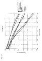
- FIG. 22 shows selected test results with the filter bags according to the invention which are compared with the filter bags according to comparative examples 1* to 3*.
- the filter bags represented in FIGS. 1 to 21 were measured in a test series (implemented with a vacuum cleaner by Miele, type 5210) with defined quantities of DMT-standard dust type 8 (50-400 g, respectively in 50 g interval steps).
- DMT-standard dust type 8 50-400 g, respectively in 50 g interval steps.
- the measurement values are indicated for the filter bags in Table 1.
- the two lower lines of the table respectively show the measured pressure loss in % after picking up 200 or 400 g DMT-standard dust, this value being determined by the measured pressure value after picking up the respective quantity of dust, relative to the measured pressure, in the case of the dust filter bag inserted in the vacuum cleaner without having previously picked up dust.
- the dust filter bags according to the invention have a significantly increased lifespan or dust pick-up capacity relative to the filter bags according to comparative examples 1* and 2*.
- the filter bag of comparative example 3* known from the state of the art see FIG.
- filter bags according to the invention for the most part likewise improved test results with respect to the dust storage capacity and lifespan can be established, whilst many filter bags according to the invention, with respect to the dust pick-up capacity and lifespan, are almost equal to the filter bag according to comparative example 3*.
- FIG. 22 selected test results with the filter bags according to the invention are compared with the filter bags according to comparative examples 1* to 3*.
- a comparison of the obtained measurement values with comparative examples 1* to 3* takes place respectively. It can be detected clearly that the filter bags according to the invention are clearly superior to the filter bags according to the comparative examples 1* and 2* with respect to the pressure decrease in the case of a previously defined picked-up quantity of dust, whilst equal results or slight improvements can be observed with respect to the filter bag according to comparative example 3*.
Landscapes
- Engineering & Computer Science (AREA)
- Mechanical Engineering (AREA)
- Filtering Of Dispersed Particles In Gases (AREA)
- Filters For Electric Vacuum Cleaners (AREA)
- Filtering Materials (AREA)
- Bag Frames (AREA)
Applications Claiming Priority (4)
| Application Number | Priority Date | Filing Date | Title |
|---|---|---|---|
| EP09008064 | 2009-06-19 | ||
| EP09008064.9 | 2009-06-19 | ||
| EP09008064.9A EP2263507B1 (de) | 2009-06-19 | 2009-06-19 | Flachbeutel für staubsauger |
| PCT/EP2010/003018 WO2010145740A1 (de) | 2009-06-19 | 2010-05-17 | Flachbeutel für staubsauger |
Publications (2)
| Publication Number | Publication Date |
|---|---|
| US20120272628A1 US20120272628A1 (en) | 2012-11-01 |
| US8702828B2 true US8702828B2 (en) | 2014-04-22 |
Family
ID=41259437
Family Applications (1)
| Application Number | Title | Priority Date | Filing Date |
|---|---|---|---|
| US13/377,668 Active 2030-07-02 US8702828B2 (en) | 2009-06-19 | 2010-05-17 | Flat bag for vacuum cleaners |
Country Status (9)
| Country | Link |
|---|---|
| US (1) | US8702828B2 (de) |
| EP (4) | EP2263507B1 (de) |
| CN (1) | CN102802484B (de) |
| AU (1) | AU2010262163B2 (de) |
| DE (1) | DE202010018626U1 (de) |
| DK (3) | DK3195782T3 (de) |
| ES (4) | ES2694479T3 (de) |
| PL (3) | PL3195782T3 (de) |
| WO (1) | WO2010145740A1 (de) |
Cited By (1)
| Publication number | Priority date | Publication date | Assignee | Title |
|---|---|---|---|---|
| US20130047563A1 (en) * | 2010-03-19 | 2013-02-28 | Ralf Sauer | Vacuum Cleaner Filter Bag |
Families Citing this family (12)
| Publication number | Priority date | Publication date | Assignee | Title |
|---|---|---|---|---|
| ES2713045T3 (es) | 2011-03-22 | 2019-05-17 | Eurofilters Nv | Dispositivo ecológicamente eficiente para la aspiración de polvo |
| DE202011108953U1 (de) | 2011-12-02 | 2012-01-19 | Branofilter Gmbh | Staubfilterbeutel mit einer Staubfängereinlage |
| DE102011120688B4 (de) | 2011-12-02 | 2019-05-16 | Branofilter Gmbh | Staubfilterbeutel mit einer Staubfängereinlage |
| EP2644077A1 (de) | 2012-03-27 | 2013-10-02 | Jan Schultink | Verfahren zum Optimieren einer Vorrichtung zum Staubsaugen mit Hand-, Kompakt oder Upright-Staubsaugergerät und Filterbeutel |
| EP2644075A1 (de) | 2012-03-27 | 2013-10-02 | Jan Schultink | Verfahren zum Optimieren einer Vorrichtung zum Staubsaugen mit Boden- oder Upright-Staubsaugergerät und Filterbeutel |
| DE102013100795A1 (de) * | 2013-01-28 | 2014-07-31 | Miele & Cie. Kg | Filterbeutel für Staubsauger |
| ES2566904T3 (es) | 2013-03-15 | 2016-04-18 | Eurofilters Holding N.V. | Bolsa de filtro de aspirador |
| CN104116462B (zh) * | 2013-04-26 | 2017-06-30 | 天佑电器(苏州)有限公司 | 过滤袋及具有该过滤袋的吸尘器 |
| EP2835087B1 (de) | 2013-08-09 | 2018-10-10 | Eurofilters N.V. | Staubsaugerfilterbeutel mit beabstandungselement |
| EP3305155B1 (de) | 2016-10-06 | 2019-05-22 | Eurofilters N.V. | Staubsaugerfilterbeutel mit recycliertem textilmaterialien und/oder baumwolllinters |
| US12016515B2 (en) | 2016-03-17 | 2024-06-25 | Eurofilters N.V. | Vacuum cleaner filter bag with recycled textile materials and/or cotton liners |
| DK3219376T3 (en) | 2016-03-17 | 2019-01-14 | Eurofilters Nv | Vacuum cleaner filter bag of recycled plastics |
Citations (17)
| Publication number | Priority date | Publication date | Assignee | Title |
|---|---|---|---|---|
| US2732911A (en) | 1956-01-31 | Disposable dust bags for vacuum cleaners | ||
| EP0960645A2 (de) | 1998-05-11 | 1999-12-01 | Airflo Europe N.V. | Staubfilterbeutel für einen Staubsauger oder Filter, und Verfahren zum Filtern eines Gases |
| US6063171A (en) | 1998-11-16 | 2000-05-16 | Electrolux Llc | Bactericidal vacuum cleaner filter bag |
| DE202006016304U1 (de) | 2006-10-23 | 2006-12-21 | Wolf Gmbh & Co. Kg | Filterbeutel |
| DE202006016303U1 (de) | 2006-10-23 | 2006-12-21 | Wolf Gmbh & Co. Kg | Filterbeutel |
| DE202006019108U1 (de) | 2006-12-19 | 2007-02-22 | Branofilter Gmbh | Staubfilterbeutel |
| EP1787560A1 (de) | 2005-11-22 | 2007-05-23 | Eurofilters Holding N.V | Staubsaugerfilterbeutel mit Ablenkvorrichtung |
| EP1795247A1 (de) | 2005-12-12 | 2007-06-13 | Eurofilters N.V. | Filterbeutel für einen Staubsauger sowie dessen Verwendung |
| EP1804635A1 (de) | 2005-11-22 | 2007-07-11 | Eurofilters Holding N.V | Staubsaugerfilterbeutel und verwendung eines staubsaugefilterbeutels |
| DE202007010692U1 (de) | 2007-08-01 | 2007-10-04 | Branofilter Gmbh | Filtervorrichtung in Gestalt eines Staubfilterbeutels oder einer Filtertasche |
| DE102006051117B3 (de) | 2005-10-14 | 2008-01-31 | Papierverarbeitung Görlitz GmbH | Staubfilterbeutel für Staubsauger |
| DE202008003248U1 (de) | 2008-03-07 | 2008-05-08 | Eurofilters Holding N.V. | Staubsaugerfilterbeutel |
| DE202008007717U1 (de) | 2008-06-10 | 2008-08-07 | Wolf Pvg Gmbh & Co. Kg | Filterbeutel |
| US8066803B2 (en) * | 2006-11-03 | 2011-11-29 | Eurofilters Holding N.V. | Vacuum cleaner filter bag |
| US8092562B2 (en) * | 2006-04-25 | 2012-01-10 | Eurofilters Holding N.V. | Holding plate for a vacuum cleaner filter bag |
| US8372174B2 (en) * | 2008-03-07 | 2013-02-12 | Eurofilters Holding N.V. | Vacuum filter cleaner bag |
| US8449639B2 (en) * | 2007-08-17 | 2013-05-28 | Eurofilters Holding N.V. | Vacuum cleaner filter bag |
Family Cites Families (5)
| Publication number | Priority date | Publication date | Assignee | Title |
|---|---|---|---|---|
| US3370405A (en) * | 1964-12-18 | 1968-02-27 | Studley Paper Company Inc | Vacuum cleaner filter bags and method of manufacturing same |
| US5647881A (en) * | 1995-04-20 | 1997-07-15 | Minnesota Mining And Manufacturing Company | Shock resistant high efficiency vacuum cleaner filter bag |
| JP4200980B2 (ja) | 2005-04-13 | 2008-12-24 | 株式会社デンソー | 車載用衝突物判定装置 |
| DE102008045683B4 (de) | 2008-09-04 | 2012-08-16 | Branofilter Gmbh | Staubfilterbeuteleinrichtung für einen Staubsauger |
| DE102008061250C5 (de) † | 2008-12-10 | 2018-12-20 | Wolf Pvg Gmbh & Co. Kg | Staubsaugerbeutel und Verfahren zur Herstellung eines Staubsaugerbeutels |
-
2009
- 2009-06-19 ES ES09008064.9T patent/ES2694479T3/es active Active
- 2009-06-19 ES ES18196359T patent/ES2876248T3/es active Active
- 2009-06-19 DK DK17160494.5T patent/DK3195782T3/en active
- 2009-06-19 EP EP09008064.9A patent/EP2263507B1/de active Active
- 2009-06-19 EP EP18196359.6A patent/EP3443880B1/de active Active
- 2009-06-19 DK DK09008064.9T patent/DK2263507T3/en active
- 2009-06-19 ES ES17160494T patent/ES2716753T3/es active Active
- 2009-06-19 PL PL17160494T patent/PL3195782T3/pl unknown
- 2009-06-19 PL PL18196359T patent/PL3443880T3/pl unknown
- 2009-06-19 DK DK18196359.6T patent/DK3443880T3/da active
- 2009-06-19 PL PL09008064T patent/PL2263507T3/pl unknown
- 2009-06-19 EP EP17160494.5A patent/EP3195782B1/de active Active
-
2010
- 2010-05-17 AU AU2010262163A patent/AU2010262163B2/en active Active
- 2010-05-17 CN CN201080027292.8A patent/CN102802484B/zh active Active
- 2010-05-17 WO PCT/EP2010/003018 patent/WO2010145740A1/de not_active Ceased
- 2010-05-17 US US13/377,668 patent/US8702828B2/en active Active
- 2010-05-17 ES ES10721327T patent/ES2595602T5/es active Active
- 2010-05-17 EP EP10721327.4A patent/EP2442702B2/de active Active
- 2010-05-17 DE DE202010018626.9U patent/DE202010018626U1/de not_active Expired - Lifetime
Patent Citations (20)
| Publication number | Priority date | Publication date | Assignee | Title |
|---|---|---|---|---|
| US2732911A (en) | 1956-01-31 | Disposable dust bags for vacuum cleaners | ||
| EP0960645A2 (de) | 1998-05-11 | 1999-12-01 | Airflo Europe N.V. | Staubfilterbeutel für einen Staubsauger oder Filter, und Verfahren zum Filtern eines Gases |
| US6063171A (en) | 1998-11-16 | 2000-05-16 | Electrolux Llc | Bactericidal vacuum cleaner filter bag |
| DE102006051117B3 (de) | 2005-10-14 | 2008-01-31 | Papierverarbeitung Görlitz GmbH | Staubfilterbeutel für Staubsauger |
| EP1787560A1 (de) | 2005-11-22 | 2007-05-23 | Eurofilters Holding N.V | Staubsaugerfilterbeutel mit Ablenkvorrichtung |
| EP1804635A1 (de) | 2005-11-22 | 2007-07-11 | Eurofilters Holding N.V | Staubsaugerfilterbeutel und verwendung eines staubsaugefilterbeutels |
| EP1795247A1 (de) | 2005-12-12 | 2007-06-13 | Eurofilters N.V. | Filterbeutel für einen Staubsauger sowie dessen Verwendung |
| US8092562B2 (en) * | 2006-04-25 | 2012-01-10 | Eurofilters Holding N.V. | Holding plate for a vacuum cleaner filter bag |
| DE202006016304U1 (de) | 2006-10-23 | 2006-12-21 | Wolf Gmbh & Co. Kg | Filterbeutel |
| DE202006016303U1 (de) | 2006-10-23 | 2006-12-21 | Wolf Gmbh & Co. Kg | Filterbeutel |
| US8066803B2 (en) * | 2006-11-03 | 2011-11-29 | Eurofilters Holding N.V. | Vacuum cleaner filter bag |
| DE202006019108U1 (de) | 2006-12-19 | 2007-02-22 | Branofilter Gmbh | Staubfilterbeutel |
| DE202007010692U1 (de) | 2007-08-01 | 2007-10-04 | Branofilter Gmbh | Filtervorrichtung in Gestalt eines Staubfilterbeutels oder einer Filtertasche |
| US8449639B2 (en) * | 2007-08-17 | 2013-05-28 | Eurofilters Holding N.V. | Vacuum cleaner filter bag |
| DE202008003248U1 (de) | 2008-03-07 | 2008-05-08 | Eurofilters Holding N.V. | Staubsaugerfilterbeutel |
| DE202008008989U1 (de) | 2008-03-07 | 2008-09-04 | Eurofilters Holding N.V. | Staubsaugerfilterbeutel |
| US8372174B2 (en) * | 2008-03-07 | 2013-02-12 | Eurofilters Holding N.V. | Vacuum filter cleaner bag |
| DE202008007717U1 (de) | 2008-06-10 | 2008-08-07 | Wolf Pvg Gmbh & Co. Kg | Filterbeutel |
| US20090301043A1 (en) | 2008-06-10 | 2009-12-10 | Wolf Pvg Gmbh & Co. Kg | Filter bag |
| US8236078B2 (en) * | 2008-06-10 | 2012-08-07 | Wolf Pvg Gmbh & Co. Kg | Filter bag |
Cited By (6)
| Publication number | Priority date | Publication date | Assignee | Title |
|---|---|---|---|---|
| US20130047563A1 (en) * | 2010-03-19 | 2013-02-28 | Ralf Sauer | Vacuum Cleaner Filter Bag |
| US20130055900A1 (en) * | 2010-03-19 | 2013-03-07 | Ralf Sauer | Vacuum Cleaner Filter Bag |
| US20130061566A1 (en) * | 2010-03-19 | 2013-03-14 | Ralf Sauer | Vacuum Cleaner Filter Bag |
| US10178932B2 (en) * | 2010-03-19 | 2019-01-15 | Eurofilters Holding N.V. | Vacuum cleaner filter bag |
| US10182691B2 (en) * | 2010-03-19 | 2019-01-22 | Eurofilters Holding N.V. | Vacuum cleaner filter bag |
| US10188248B2 (en) * | 2010-03-19 | 2019-01-29 | Eurofilters Holding N.V. | Vacuum cleaner filter bag |
Also Published As
| Publication number | Publication date |
|---|---|
| CN102802484B (zh) | 2016-08-03 |
| AU2010262163A1 (en) | 2012-01-19 |
| EP2442702A1 (de) | 2012-04-25 |
| ES2595602T3 (es) | 2017-01-02 |
| DK2263507T3 (en) | 2019-01-14 |
| DE202010018626U1 (de) | 2019-05-09 |
| DK3443880T3 (da) | 2021-07-26 |
| WO2010145740A1 (de) | 2010-12-23 |
| AU2010262163B2 (en) | 2016-03-24 |
| DK3195782T3 (en) | 2019-04-15 |
| CN102802484A (zh) | 2012-11-28 |
| EP2442702B2 (de) | 2023-01-11 |
| ES2694479T3 (es) | 2018-12-21 |
| EP3195782A1 (de) | 2017-07-26 |
| EP3443880B1 (de) | 2021-05-12 |
| EP2263507B1 (de) | 2018-09-19 |
| US20120272628A1 (en) | 2012-11-01 |
| PL3195782T3 (pl) | 2019-07-31 |
| ES2595602T5 (es) | 2023-03-30 |
| EP3443880A1 (de) | 2019-02-20 |
| EP2263507A1 (de) | 2010-12-22 |
| EP2442702B1 (de) | 2016-08-31 |
| EP3195782B1 (de) | 2019-01-09 |
| PL3443880T3 (pl) | 2021-12-06 |
| ES2716753T3 (es) | 2019-06-14 |
| PL2263507T3 (pl) | 2019-02-28 |
| ES2876248T3 (es) | 2021-11-12 |
Similar Documents
| Publication | Publication Date | Title |
|---|---|---|
| US8702827B2 (en) | Flat bag for vacuum cleaners | |
| US20120272628A1 (en) | Flat bag for vacuum cleaners | |
| US8372174B2 (en) | Vacuum filter cleaner bag | |
| US10178932B2 (en) | Vacuum cleaner filter bag | |
| US8758465B2 (en) | Block-base bag for vacuum cleaners | |
| US8974566B2 (en) | Vacuum cleaner filter bag having a side fold | |
| US20080314005A1 (en) | Vacuum Cleaner Filter Bag and Use of Said Bag | |
| US20140075713A1 (en) | Ecologically Efficient Vacuuming Device | |
| NZ615445B2 (en) | Ecologically efficient vacuuming device |
Legal Events
| Date | Code | Title | Description |
|---|---|---|---|
| AS | Assignment |
Owner name: EUROFILTERS HOLDING N. V., BELGIUM Free format text: ASSIGNMENT OF ASSIGNORS INTEREST;ASSIGNORS:SCHULTINK, JAN;SAUER, RALF;REEL/FRAME:028683/0222 Effective date: 20111221 |
|
| STCF | Information on status: patent grant |
Free format text: PATENTED CASE |
|
| MAFP | Maintenance fee payment |
Free format text: PAYMENT OF MAINTENANCE FEE, 4TH YEAR, LARGE ENTITY (ORIGINAL EVENT CODE: M1551) Year of fee payment: 4 |
|
| MAFP | Maintenance fee payment |
Free format text: PAYMENT OF MAINTENANCE FEE, 8TH YEAR, LARGE ENTITY (ORIGINAL EVENT CODE: M1552); ENTITY STATUS OF PATENT OWNER: LARGE ENTITY Year of fee payment: 8 |
|
| MAFP | Maintenance fee payment |
Free format text: PAYMENT OF MAINTENANCE FEE, 12TH YEAR, LARGE ENTITY (ORIGINAL EVENT CODE: M1553); ENTITY STATUS OF PATENT OWNER: LARGE ENTITY Year of fee payment: 12 |