US8714365B2 - Fruit handling equipment - Google Patents
Fruit handling equipment Download PDFInfo
- Publication number
- US8714365B2 US8714365B2 US13/145,150 US201013145150A US8714365B2 US 8714365 B2 US8714365 B2 US 8714365B2 US 201013145150 A US201013145150 A US 201013145150A US 8714365 B2 US8714365 B2 US 8714365B2
- Authority
- US
- United States
- Prior art keywords
- fruit
- carriage
- handling equipment
- conveyor
- cup
- Prior art date
- Legal status (The legal status is an assumption and is not a legal conclusion. Google has not performed a legal analysis and makes no representation as to the accuracy of the status listed.)
- Active, expires
Links
Images


Classifications
-
- B—PERFORMING OPERATIONS; TRANSPORTING
- B65—CONVEYING; PACKING; STORING; HANDLING THIN OR FILAMENTARY MATERIAL
- B65G—TRANSPORT OR STORAGE DEVICES, e.g. CONVEYORS FOR LOADING OR TIPPING, SHOP CONVEYOR SYSTEMS OR PNEUMATIC TUBE CONVEYORS
- B65G47/00—Article or material-handling devices associated with conveyors; Methods employing such devices
- B65G47/74—Feeding, transfer, or discharging devices of particular kinds or types
- B65G47/94—Devices for flexing or tilting travelling structures; Throw-off carriages
- B65G47/96—Devices for tilting links or platform
- B65G47/962—Devices for tilting links or platform tilting about an axis substantially parallel to the conveying direction
- B65G47/965—Devices for tilting links or platform tilting about an axis substantially parallel to the conveying direction tilting about a sided-axis, i.e. the axis is not located near the center-line of the load-carrier
-
- B—PERFORMING OPERATIONS; TRANSPORTING
- B07—SEPARATING SOLIDS FROM SOLIDS; SORTING
- B07C—POSTAL SORTING; SORTING INDIVIDUAL ARTICLES, OR BULK MATERIAL FIT TO BE SORTED PIECE-MEAL, e.g. BY PICKING
- B07C5/00—Sorting according to a characteristic or feature of the articles or material being sorted, e.g. by control effected by devices which detect or measure such characteristic or feature; Sorting by manually actuated devices, e.g. switches
- B07C5/36—Sorting apparatus characterised by the means used for distribution
-
- B—PERFORMING OPERATIONS; TRANSPORTING
- B65—CONVEYING; PACKING; STORING; HANDLING THIN OR FILAMENTARY MATERIAL
- B65G—TRANSPORT OR STORAGE DEVICES, e.g. CONVEYORS FOR LOADING OR TIPPING, SHOP CONVEYOR SYSTEMS OR PNEUMATIC TUBE CONVEYORS
- B65G17/00—Conveyors having an endless traction element, e.g. a chain, transmitting movement to a continuous or substantially-continuous load-carrying surface or to a series of individual load-carriers; Endless-chain conveyors in which the chains form the load-carrying surface
- B65G17/24—Conveyors having an endless traction element, e.g. a chain, transmitting movement to a continuous or substantially-continuous load-carrying surface or to a series of individual load-carriers; Endless-chain conveyors in which the chains form the load-carrying surface comprising a series of rollers which are moved, e.g. over a supporting surface, by the traction element to effect conveyance of loads or load-carriers
-
- B—PERFORMING OPERATIONS; TRANSPORTING
- B65—CONVEYING; PACKING; STORING; HANDLING THIN OR FILAMENTARY MATERIAL
- B65G—TRANSPORT OR STORAGE DEVICES, e.g. CONVEYORS FOR LOADING OR TIPPING, SHOP CONVEYOR SYSTEMS OR PNEUMATIC TUBE CONVEYORS
- B65G23/00—Driving gear for endless conveyors; Belt- or chain-tensioning arrangements
- B65G23/02—Belt- or chain-engaging elements
- B65G23/04—Drums, rollers, or wheels
- B65G23/06—Drums, rollers, or wheels with projections engaging abutments on belts or chains, e.g. sprocket wheels
-
- B—PERFORMING OPERATIONS; TRANSPORTING
- B65—CONVEYING; PACKING; STORING; HANDLING THIN OR FILAMENTARY MATERIAL
- B65G—TRANSPORT OR STORAGE DEVICES, e.g. CONVEYORS FOR LOADING OR TIPPING, SHOP CONVEYOR SYSTEMS OR PNEUMATIC TUBE CONVEYORS
- B65G23/00—Driving gear for endless conveyors; Belt- or chain-tensioning arrangements
- B65G23/02—Belt- or chain-engaging elements
- B65G23/14—Endless driving elements extending parallel to belt or chain
- B65G23/16—Endless driving elements extending parallel to belt or chain with dogs engaging abutments on belts or chains
-
- B—PERFORMING OPERATIONS; TRANSPORTING
- B65—CONVEYING; PACKING; STORING; HANDLING THIN OR FILAMENTARY MATERIAL
- B65G—TRANSPORT OR STORAGE DEVICES, e.g. CONVEYORS FOR LOADING OR TIPPING, SHOP CONVEYOR SYSTEMS OR PNEUMATIC TUBE CONVEYORS
- B65G47/00—Article or material-handling devices associated with conveyors; Methods employing such devices
- B65G47/34—Devices for discharging articles or materials from conveyor
- B65G47/46—Devices for discharging articles or materials from conveyor and distributing, e.g. automatically, to desired points
- B65G47/50—Devices for discharging articles or materials from conveyor and distributing, e.g. automatically, to desired points according to destination signals stored in separate systems
- B65G47/503—Devices for discharging articles or materials from conveyor and distributing, e.g. automatically, to desired points according to destination signals stored in separate systems the system comprising endless moving means
-
- B—PERFORMING OPERATIONS; TRANSPORTING
- B65—CONVEYING; PACKING; STORING; HANDLING THIN OR FILAMENTARY MATERIAL
- B65G—TRANSPORT OR STORAGE DEVICES, e.g. CONVEYORS FOR LOADING OR TIPPING, SHOP CONVEYOR SYSTEMS OR PNEUMATIC TUBE CONVEYORS
- B65G2201/00—Indexing codes relating to handling devices, e.g. conveyors, characterised by the type of product or load being conveyed or handled
- B65G2201/02—Articles
- B65G2201/0202—Agricultural and processed food products
- B65G2201/0211—Fruits and vegetables
-
- B—PERFORMING OPERATIONS; TRANSPORTING
- B65—CONVEYING; PACKING; STORING; HANDLING THIN OR FILAMENTARY MATERIAL
- B65G—TRANSPORT OR STORAGE DEVICES, e.g. CONVEYORS FOR LOADING OR TIPPING, SHOP CONVEYOR SYSTEMS OR PNEUMATIC TUBE CONVEYORS
- B65G2203/00—Indexing code relating to control or detection of the articles or the load carriers during conveying
- B65G2203/02—Control or detection
- B65G2203/0208—Control or detection relating to the transported articles
- B65G2203/0216—Codes or marks on the article
-
- B—PERFORMING OPERATIONS; TRANSPORTING
- B65—CONVEYING; PACKING; STORING; HANDLING THIN OR FILAMENTARY MATERIAL
- B65G—TRANSPORT OR STORAGE DEVICES, e.g. CONVEYORS FOR LOADING OR TIPPING, SHOP CONVEYOR SYSTEMS OR PNEUMATIC TUBE CONVEYORS
- B65G2203/00—Indexing code relating to control or detection of the articles or the load carriers during conveying
- B65G2203/02—Control or detection
- B65G2203/0208—Control or detection relating to the transported articles
- B65G2203/0258—Weight of the article
-
- B—PERFORMING OPERATIONS; TRANSPORTING
- B65—CONVEYING; PACKING; STORING; HANDLING THIN OR FILAMENTARY MATERIAL
- B65G—TRANSPORT OR STORAGE DEVICES, e.g. CONVEYORS FOR LOADING OR TIPPING, SHOP CONVEYOR SYSTEMS OR PNEUMATIC TUBE CONVEYORS
- B65G2203/00—Indexing code relating to control or detection of the articles or the load carriers during conveying
- B65G2203/04—Detection means
- B65G2203/041—Camera
-
- B—PERFORMING OPERATIONS; TRANSPORTING
- B65—CONVEYING; PACKING; STORING; HANDLING THIN OR FILAMENTARY MATERIAL
- B65G—TRANSPORT OR STORAGE DEVICES, e.g. CONVEYORS FOR LOADING OR TIPPING, SHOP CONVEYOR SYSTEMS OR PNEUMATIC TUBE CONVEYORS
- B65G2203/00—Indexing code relating to control or detection of the articles or the load carriers during conveying
- B65G2203/04—Detection means
- B65G2203/042—Sensors
Definitions
- This invention relates to fruit handling equipment and, in particular, relates to a conveyor system which carries fruit that is rotated past a photographic zone, weighed at a weighing zone and then ejected into appropriately positioned bins in dependence on the characteristics of the fruit as determined by the images taken at the photographic zone and the weight recorded at the weighing zone.
- fruit as used herein embraces part spherical fruit and vegetables such as citrus fruits, apples, potatoes, tomatoes, and like shaped articles.
- Equipment of this kind usually utilises a series of carriages which are clipped onto a chain driven by sprockets.
- the carriages carry cups which support the fruit.
- a series of rotating rollers are arranged to rotate the fruit clear of the cups through a photographic zone.
- the fruit is then carried by the cups over a weighing zone in which the weight of each fruit is monitored.
- the cups are usually designed to pivot outwardly to cause the fruit to be ejected at appropriate positions along the conveyor determined by a computer that stores the data from the photographic and weighing zones.
- Equipment of this kind is very complex and thus expensive.
- the timing of the operation of components of the equipment is critical and thus setting up the equipment is a lengthy operation for a skilled individual.
- the power consumption of the motors which drive the sprockets is significant.
- a fruit handling equipment comprising a first conveyor adapted to transport a line of single pieces of fruit past a camera, over a load cell and through an ejection zone to eject the fruit at predetermined positions along the conveyor, and a second conveyor adapted to mesh with the first conveyor to lift the fruit off the first conveyor and rotate the fruit as it moves past the camera, characterised in that the first conveyor is a chain of fruit carrying carriages pivotally secured end-to-end to define a closed loop, and the second conveyor comprises a plurality of roller supports pivotally secured end-to-end to define a shorter closed loop, whereby each carriage pulls the adjacent meshing roller support.
- the fruit carrying carriages interlink with the roller carriages and the first conveyor drives the second conveyor.
- the respective carriages have interfitting formations which accurately line up the carriages and roller supports as the conveyor integrates.
- the fruit carrying carriages and roller supports are manufactured in plastics.
- a fruit handling equipment comprising a conveyor having a plurality of linked carriages, each supporting a fruit carrying cup supported in a cantilever fashion from each side of the carriage, each cup having a latching mechanism operable to hold the cup in a fruit carrying mode and releasable to cause the cup to pivot to a delatched position to eject the fruit, and remotely controllable means in each carriage to release the latching mechanism.
- each carriage carries a radio controlled solenoid to trigger release of the latching mechanism.
- the solenoid may be powered by induction.
- FIG. 1 is a side elevational view schematically showing a two lanes of fruit handling equipment
- FIG. 2 is a perspective view of the pair of lanes illustrating the inter-engagement of two conveyors forming part of the fruit handling equipment;
- FIG. 3 a is a perspective view of a roller assembly
- FIG. 3 b is a side elevational view of the roller assembly
- FIG. 3 c is a plan view of the roller assembly
- FIG. 3 d is an end elevational view of the roller assembly
- FIG. 4 a is a perspective view of a cup carriage assembly with the cups in a latched position
- FIG. 4 b is a perspective view of the cup carriage assembly with one cup unlatched
- FIG. 4 c is a sectioned perspective view of the cup carriage assembly with components removed to illustrate the latching assembly
- FIG. 5 a is a plan view of one side of the cup carriage assembly
- FIG. 5 b is a sectional view taken along the lines A-A of FIG. 5 a;
- FIG. 5 c is the same section view but showing a cup in a delatched positioned
- FIG. 6 is a section view taken along the lines A-A of FIG. 5 a showing the cup in a weighing position
- FIG. 7 a is a plan view of the cup carriage conveyor superimposed with the roller conveyor
- FIG. 7 b is a cross sectional view taken through the lines A-A of FIG. 7 a;
- FIG. 7 c is a side elevational view of the assembly shown in FIG. 7 a;
- FIG. 8 is a plan view showing part of a sprocket driving the cup carriage assemblies
- FIG. 9 is a cross sectional view taken along the lines A-A of FIG. 8 and a partial section view taken along the lines BB of FIG. 8 ;
- FIG. 10 is a perspective view of a cup carriage running on a rail of the conveyor
- FIG. 11 is a sectional view of the carriage running on the rail
- FIG. 12 is a schematic circuit diagram illustrating the association of a radio transceiver and power supply with the fruit handling equipment.
- FIG. 13 illustrates the electrical circuitry carried by each carriage.
- the fruit handling equipment of the preferred embodiment essentially comprises a series of parallel lanes each comprising a main conveyor 10 of interlinked fruit carrying carriage assemblies 20 that integrates with a second roller conveyor 11 at one end.
- a pair of lanes is illustrated in FIGS. 1 and 2 .
- the roller conveyor comprising a closed loop of pivotally interconnected roller assemblies 40 .
- the roller conveyor 11 is arranged to freely rotate around semi-circular guide drums 12 , 13 positioned at each end of the conveyor 11 whereby as the main conveyor 10 returns, the carriage assemblies 20 mesh with the roller assemblies 40 to pass together through a photographic zone A near the end 15 of the main conveyor 10 .
- the roller conveyor 11 descends a ramp 19 to disengage from the cup carriage assemblies 20 to return around the semi-circular guide drum 13 .
- the fruit carrying carriage assemblies 20 of the main conveyor 10 then continue to pass through a weighing zone B to an ejection zone C to return on the underside of the main conveyor 10 as shown in FIG. 1 .
- the portion of the conveyor between the carriage and drum assembly separation and end 16 of the conveyor 10 is referred to as the active zone (AZ).
- the main conveyor 10 is driven at one end 16 by a metal sprocket 17 with plastic tipped teeth 18 and runs at the other end 15 integrated with the roller conveyor 11 on the drum 12 .
- the integration of the two conveyors 10 and 11 ensures that the main conveyor 10 drives the roller conveyor 11 around the drums 12 , 13 .
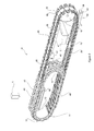
- each roller assembly 40 of the roller conveyor 11 comprises a roller support 41 having two pairs of parallel flanges 42 , 43 which extend in opposite directions parallel to the longitudinal axis of the conveyor 11 .
- the flanges 42 , 43 support each end of a spindle 44 which supports a roller 45 .
- the roller 45 comprises two frusto-conical central members 46 , 47 and two larger tapered outer members 48 , 49 defining gaps therebetween.
- roller conveyor is made up of a series of interlinked roller assemblies 40 joined through the spindles 44 to provide a series of pivotal links forming the closed loop which constitutes the roller conveyor 11 .
- the roller support has an upstanding tooth 98 designed to fit in the slot 62 created between 2 adjacent carriages 20 thereby locating each roller assembly with respect to the carriage conveyor 10 when the two conveyors merge as shown in FIG. 7 b .
- the leading vertical flange 96 of the carriage 20 acts against the upstanding tooth 98 of the roller support causing the roller conveyor 11 to be driven by the main conveyor 10 .
- the main conveyor 10 is constituted by a series of links made up by interconnection of the fruit carrying carriage assemblies 20 .
- Each carriage assembly 20 as shown in FIGS. 4 to 6 , comprises a central carriage 21 which pivotally supports a pair of laterally extending radius arms 22 on each side, each radius arm 22 in turn supporting a fruit carrying cup 23 .
- the carriage 21 is of rectangular profile with a substantially planar underside 24 and an open recess 28 covered by a removable cover 29 with a pair of outwardly extending flanges 25 at one end supporting a pair of wheels 26 on an axle 27 .
- the radius arm 22 comprises a curved beam with a T-shaped mounting flange 33 on one end which is pivotally secured across the side of the carriage 21 .
- the opposite end of the radius arm pivotally supports one end of the cup 23 through an elongate pivot 39 .
- the underside of the cup has two spaced legs 34 , 35 that are arranged to extend freely through a pair of spaced apertures 36 , 37 in the curved beam 22 of the radius arm.
- the pivotal connection of the radius arm 22 to the carriage 21 allows the cup to be supported in a fruit carrying position shown in FIG. 4 a and an ejection position shown in FIG. 4 b in which the radius arm 22 pivots downwardly to eject fruit carried by the cup 23 .
- each cup 23 comprises a dished recess defined by five fingers 30 to define gaps 31 therebetween.
- the gaps 31 between the fingers 30 of the dish-shaped cup 23 are designed so that when the two conveyors are integrated and the roller assemblies 40 are superimposed on the carriage assemblies 20 the upper surfaces of each roller 45 can extend through the gaps 31 to engage the underside of the fruit to lift the fruit clear of the cup 23 for rotation through the photographic zone A as shown in FIGS. 1 and 2 .
- the conveyors 10 and 11 part causing the rollers 45 to be lowered, as shown in FIG. 8 , so that a single piece of fruit then rests on the dish-shaped cup 23 .
- the radius arm 22 has a downwardly extending foot 38 that engages a latching mechanism 50 mounted in the recess 28 of the carriage 21 to control the position of the cup 23 relative to the carriage 21 .
- the latching mechanism 50 is a long piece of plastic moulding which includes an L-shaped latching arm 51 that is pivotally secured to the base of the carriage and a trailing detent 52 that is flexibly formed integrally with the rest of the moulding.
- the detent 52 has a trailing abutment 53 behind a shoulder 54 which is arranged to engage the base 55 of a well 70 formed in the centre of the cover 29 of the carriage.
- the L-shaped arm 51 accommodates the base of the foot 38 of the radius arm 22 and, as shown in FIG.
- the cups 23 remain in the unlatched configuration as they round the end 16 of the conveyor 10 . As they invert, gravity causes the cups 23 to return to the longitudinal position and an inclined plastic ramp 75 on the return consolidates the latching mechanism 50 of each cup 23 .
- each carriage assemblies 20 When the main conveyor 10 is assembled, the carriage assemblies 20 are pivotally interconnected through the shaft 27 on the wheels 26 so that there is wheeled support at each end of each carriage 21 .
- These wheels 26 are arranged to run on tracks 60 , 61 that are formed by open rectangular aluminium beams 60 , 61 which are located on the underside of the top of the main conveyor 10 and on the underside of the return, as shown in FIGS. 1 and 2 .
- each beam 60 , 61 has an open top with inturned flanges 68 , 69 that support the wheels 26 .
- the position of the wheels 26 in the carriage is such that, as the carriage assemblies 20 invert on the return, the wheels 26 engage the lower track 61 .
- the adjacent ends of the carriages 21 defines a rectangular slot 62 having a vertical flange 96 which, as shown in FIG. 9 , engages the teeth 18 of the drive sprocket 17 rotating in a clockwise direction to impart drive to the main carriage conveyor 10 .
- the vertical slot 62 also serves to engage with the upstanding tooth 98 on the roller supports to align and integrate the carriages 21 with the roller assembly so that the axes of the carriage wheels 26 coincide with the axes of the roller spindles 44 , thus aligning the axes of the pivot points of the links in both conveyors.
- the action of the leading vertical flange 96 of the slot 62 on the upstanding tooth 98 of the meshed roller support forces the roller conveyor 11 to move in unison with the main carriage conveyor.
- the inverted carriage assemblies 20 support the roller assemblies 40 on the track 61 .
- the roller assemblies in turn support the carriage assemblies 20 .
- a pair of driven belts 9 are positioned on each side of the conveyors 10 and 11 to engage the underside of the rollers 45 to cause them to rotate about their axes to in turn rotate the fruit as it is lifted clear of the carrying cups 23 as the two inter-engaged conveyors move past the photographic zone A.
- the belts 9 provide the support for the assembly of the two conveyors 10 and 11 .
- At least one CCD camera is located in the photographic zone A to view the rotating fruit as it passes that zone and to forward a digital signal to a computer.
- the spaced legs 34 , 35 on the underside of each cup 23 are arranged to engage a load cell 67 arranged in the path of the underside of the conveyor 11 at the weighing zone B. As shown in FIG. 6 , the load cell 67 lifts the cup 23 off the carriage 21 and ensures that there is no component of the horizontal movement distorting the actual weight measured by the load cell.
- the two-point weighing legs 34 , 35 ensure that each piece of fruit is accurately weighed as it passes over the load cell 67 . The data is then fed to the computer.
- the recess 28 which is formed in the carriage 21 , has a base that supports a first circuit board 71 and the well 70 that is positioned internally of the cover 29 houses a solenoid 72 with an upper circuit board 73 positioned on the top of the solenoid 72 .
- the solenoid has a plunger 74 that operates to push down against the abutment 53 of the detent 52 to release the latching mechanism as shown in FIGS. 5 c and 11 .
- the power to drive the solenoid 72 , the radio signal which activates the solenoid and the circuit associated with the release mechanism is illustrated in FIGS. 12 and 13 .
- the well 70 is closed off by a lid 76 which sits flush with the cover 29 of the carriage 21 .
- the cover 29 and lid 76 and the associated well 70 ensure that the latching mechanism and solenoid release and associated circuit board 73 are housed in a clean discrete area where they will not be subjected to dust and debris which is often present in apparatus such as this.
- the release of the cups 23 to the unlatched position is triggered by a remote activation system that operates on the use of a radio frequency signal to activate the solenoid.
- the section of the conveyor between the position where the rollers part from the carriages to the drive by the main sprocket is defined as the active zone (AZ) of the conveyor. It is in this zone that power is supplied to the carriages together with carefully controlled radio waves to trigger release of the latching mechanisms.
- the electrical circuitry is illustrated in FIGS. 12 and 13 .
- each rail 60 in the active zone AZ of the conveyor has transversely positioned spaced brackets 80 which have upstanding lugs 81 that support a wire coil 82 in the form a rectangular frame closed at one end.
- This coil 82 is positioned adjacent the flanges 68 , 69 which support the wheels 26 of the carriage 21 .
- the lugs 81 also supports a centrally positioned co-axial antenna cable 84 which is again positioned just under the carriage 21 .
- the first lower circuit board 71 on the base of the carriage 21 is wired to the upper circuit board 73 positioned above the solenoid 72 in the well 70 .
- the power is supplied to the solenoids by magnetic resonance inductive coupling between a long static power source coil, that is the wire coil 82 , and a small coil 85 mounted on the lower circuit board 71 in each carriage 21 .
- the magnetic inductive coupling is particularly desirable because there are no wearing parts.
- the static coil 82 is coupled to a tuning capacitor 87 as shown in FIG. 12 to cause the coil to resonate at a frequency matched by a AC power source.
- the small coil carried in the base of the carriages 21 is tuned by capacitor 86 to resonate at the same frequency as the power supply so that, as the coil passes over the static coil, energy is transferred to the moving coil.
- the AC power from the small coil on the lower circuit board 71 is rectified and regulated to supply DC power to a super capacitor 88 on the upper circuit board 73 , see circuit diagram in FIG. 13 .
- each carriage could be powered by an electronic storage device such as capacitor or battery contained in each carriage.
- the preferred method of charging the storage device is an electromagnetic coil contained in the carriage passing over a magnetic field on the conveyor which causes and electrical current to be generated in the carriage coil.
- Other methods include microwaves, electromagnetic induction, or direct driven using the motion of the conveyor carriage.
- the power may be supplied via a direct electrical contact with a supply source i.e. using brushes, pins or through the wheels.
- the power may also be supplied via a replaceable battery or other storage device.
- the radio frequency (RF) system comprises a base RF transceiver per row of carriages. Each transmitter serves two lanes and is controlled by the computer. Each carriage carries a transceiver. To minimise transmission distance from the base to the receivers, the co-axial antenna 84 runs parallel to and immediately below the carriage bases. This configuration minimises RF power and reduces the likelihood of interference between adjacent pairs of lanes. It is also understood that the use of slightly different carrier frequencies on adjacent lanes further reduces interference issues.
- the RF activity is restricted to the active section of the conveyor.
- the RF system On each remote circuit board, at the point where the capacitor charging ceases, just prior to the main drive sprocket, the RF system is switched off and the processor enters a low power consumption sleep mode. At the recommencement of charging, the processor is woken and the RF system reactivated at the start of the active zone (where the rollers separate from the carriages). As the length of the conveyor where the RF system is active corresponds with the charging zone, the super capacitor 88 remains fully charged. This capacitor is required as a buffer for the electronics when in sleep mode and for a short, high powered burst to operate solenoids S 1 and S 2 . The capacitor also maintains power to the circuit boards during short breaks in conveyor operation.
- the link (carriage assembly 20 ) houses an electronic circuit that can receive and process radio signals (or other type of electromagnetic signal) from the main conveyor controller which would be coupled to the computer.
- This signal tells the link when or where to delatch the cups.
- the conveyor controller tells the link when to drop by calculating or identifying its location and then sending the signal to delatch the cups when the link is in position at the drop point. Alternatively the conveyor controller may send the signal to the link to delatch at a predetermined location.
- the link then senses (by barcode and optical sensor, RFID tag, counting pulses to measure distance or time or other suitable means) when it has reached the correct location and delatches.
- the drive system has been specifically designed to eliminate chordal action which usually results in significant oscillation in conveyor velocity due to the large pitch conveyor chain being positioned around a relatively small drive sprocket.
- the drive sprocket 17 which directly drives the carriages 21 has sixteen teeth, each of which is covered with a plastics tip 18 to reduce noise and wear.
- a pulsing action is generated which can cause between 1% and 1.5% speed change. This is usually referred to as jitter.
- a separate smaller chain drive 92 is provided in which the output sprocket 93 on an electric motor (not shown) is coupled to a smaller drive sprocket 94 mounted on a shaft 95 which is common to the main driving sprocket 17 .
- a conventional chain 92 effects this drive.
- the smaller drive sprocket 94 is also designed to have sixteen teeth but operates at a different pitch.
- the drive to the smaller drive sprocket 94 introduces jitter in the same way that the main drive introduces jitter.
- the jitter of the smaller drive sprocket 94 is arranged to be timed to be inverse to the jitter caused by the main sprocket 17 so that the two jitters balance to provide a smooth drive.
- the majority of the components of this conveyor are manufactured from plastics.
- the plastics components are designed to be produced through a simple moulding process and the use of plastic componentry to make up the links of the two conveyors substantially reduces the overall weight of the assembly by doing away with a conventional chain to, in turn, substantially reduce the power required to drive the assembly.
- the assembly is also designed to reduce drag.
- the carriages run on wheels that engage a track even in the return configuration, see FIG. 2 . It is estimated that the assembly will operate on 25% of the power used to drive similar such assemblies.
- the use of plastics for the componentry of the assembly also substantially reduces the noise of the equipment in operation. The noise can be further reduced by coating the portion of the track which engages the wheels of the carriages and, as described earlier, coating the tips of the drive sprockets.
- Conveyors of this kind are usually 50-60 m in length and thus providing a much smaller roller conveyor of about 8 m in length substantially reduces the number of components and complexity of the arrangement.
- the inter-engagement of the two conveyors is shown with reference to FIG. 7 .
- the axes of the wheels 26 on the cup carriage assemblies 40 are arranged to align with the axes of the rollers 45 on the roller assemblies 40 .
- the underside of each roller support 41 has a central portion which defines a centrally positioned, upstanding trapezoid tooth 98 that is arranged to be a sliding fit against a vertical flange 96 at either end of the carriage 21 .
- the vertical flanges 96 of adjacent carriages 21 define leading and trailing walls of the slot 62 which accommodates the trapezoidal teeth 98 of the roller support 41 as shown in FIG. 7 b .
- the upturned roller conveyor 11 engages and supports the carriage 21 of the main conveyor 10 , causing the axles 27 , 44 of the wheels 26 and rollers 45 to align and bringing the two conveyors into a meshed configuration. Alignment of the axes of the pivot points of the roller carriages with axes of the roller assemblies when the two conveyors are meshed allows the meshed section of conveyors to flex and travel around the semicircular drive drums without any longitudinal movement between the two conveyors.
- the location of the tooth 98 against the flange 96 takes up any slack in the pivots between carriages 21 and roller supports 41 and ensures that the two conveyors 10 , 11 are accurately aligned when they come together.
- the action of the leading vertical flange 96 of the slot 62 against the tooth 98 of the roller support 41 allows the main carriage conveyor 10 to impart the driving force to the roller conveyor 11 thereby allowing the single drive sprocket 17 to power both conveyors
- the roller conveyor 11 simply drops away from the underside of the cup conveyor 10 , see FIGS. 7 b and 7 c .
- the all plastics componentry reduces the running resistance and the reduction in the number of rollers reduces the load on the main conveyor thus substantially reducing the power needed to drive the assembly. It is envisaged that the equipment described above is cheaper to build, simpler to assemble and maintain and uses substantially less energy. The assembly is quieter, more efficient and more reliable and, in consequence, easier to service. It is thought that the accuracy of the equipment will be also enhanced.
Landscapes
- Engineering & Computer Science (AREA)
- Mechanical Engineering (AREA)
- Attitude Control For Articles On Conveyors (AREA)
- Sorting Of Articles (AREA)
Applications Claiming Priority (3)
| Application Number | Priority Date | Filing Date | Title |
|---|---|---|---|
| AU2009900276A AU2009900276A0 (en) | 2009-01-23 | Fruit Handling Equipment | |
| AU2009900276 | 2009-01-23 | ||
| PCT/AU2010/000063 WO2010083567A1 (en) | 2009-01-23 | 2010-01-22 | Fruit handling equipment |
Publications (2)
| Publication Number | Publication Date |
|---|---|
| US20110309004A1 US20110309004A1 (en) | 2011-12-22 |
| US8714365B2 true US8714365B2 (en) | 2014-05-06 |
Family
ID=42355439
Family Applications (1)
| Application Number | Title | Priority Date | Filing Date |
|---|---|---|---|
| US13/145,150 Active 2030-07-02 US8714365B2 (en) | 2009-01-23 | 2010-01-22 | Fruit handling equipment |
Country Status (9)
| Country | Link |
|---|---|
| US (1) | US8714365B2 (de) |
| EP (1) | EP2389331B1 (de) |
| CN (1) | CN102292274B (de) |
| AU (1) | AU2010206498B2 (de) |
| CL (1) | CL2011001771A1 (de) |
| ES (1) | ES2640398T3 (de) |
| NZ (1) | NZ594445A (de) |
| WO (1) | WO2010083567A1 (de) |
| ZA (1) | ZA201105800B (de) |
Cited By (7)
| Publication number | Priority date | Publication date | Assignee | Title |
|---|---|---|---|---|
| US10094701B2 (en) * | 2015-04-17 | 2018-10-09 | Maf Agrobotic | Device for transporting objects and conveying and weighing device provided with such transporting devices |
| US20190135545A1 (en) * | 2016-04-28 | 2019-05-09 | Wrh Walter Reist Holding Ag | A conveying appliance with a conveying member |
| WO2019104238A1 (en) * | 2017-11-22 | 2019-05-31 | Lorin Reed | Improved produce conveying and sizing equipment |
| US20210284454A1 (en) * | 2020-03-12 | 2021-09-16 | Brown International Corporation, Llc | Systems and Methods for Moving Objects Along a Predetermined Path |
| US20220219207A1 (en) * | 2021-01-11 | 2022-07-14 | Durand-Wayland, Inc. | Produce sorting systems and methods |
| WO2023016806A1 (en) * | 2021-08-10 | 2023-02-16 | Unitec S.P.A. | Station for the conveyance and measurement of horticultural products |
| US20230192408A1 (en) * | 2021-10-05 | 2023-06-22 | Roller Conveyor, LLC | Systems and methods of sorting and conveying produce |
Families Citing this family (18)
| Publication number | Priority date | Publication date | Assignee | Title |
|---|---|---|---|---|
| NL2003516C2 (nl) * | 2009-09-21 | 2011-03-22 | Greefs Wagen Carrosserie | Transportinrichting voor het transporteren van een product, en sorteerinrichting en werkwijze daarvoor. |
| WO2013131141A1 (en) * | 2012-03-07 | 2013-09-12 | Ottimo Design Pty Ltd | Fruit handling equipment |
| ITMO20120158A1 (it) * | 2012-06-19 | 2013-12-20 | Charlotte Anna Maria Liedl | Apparecchiatura per la selezione di prodotti agricoli. |
| JP2015533649A (ja) * | 2012-11-08 | 2015-11-26 | コンパック テクノロジーズ リミティド | 格付け装置のための物品搬送器 |
| US10093490B2 (en) * | 2014-09-17 | 2018-10-09 | Unitec S.P.A. | Conveyor apparatus for the transportation and weighing of agricultural products |
| ITUB20152968A1 (it) * | 2015-08-06 | 2017-02-06 | Unitec Spa | Gruppo, e procedimento, di trattamento di prodotti ortofrutticoli. |
| CN105057226A (zh) * | 2015-08-13 | 2015-11-18 | 苏州华拓信息技术有限公司 | 瓜类农产品分拣方法 |
| ITUB20160534A1 (it) * | 2016-01-20 | 2017-07-20 | Unitec Spa | Unita' di trasporto discreto, per mirtilli e simili prodotti ortoffrutticoli |
| EP3478607B1 (de) * | 2016-07-01 | 2024-08-07 | Compac Technologies Limited | Fördersystem und artikelträger dafür |
| CN108325865B (zh) * | 2018-03-12 | 2024-03-19 | 浙江大学 | 用于果蔬分选的单链双托式果杯装置 |
| IT201800006633A1 (it) * | 2018-06-25 | 2019-12-25 | Macchina di etichettaggio | |
| CN109719041B (zh) * | 2019-02-28 | 2024-08-09 | 广东力生智能有限公司 | 分拣机台车翻盘机构 |
| CN110340029A (zh) * | 2019-07-17 | 2019-10-18 | 朱二 | 大水果分级输送单元 |
| CN110813782A (zh) * | 2019-11-19 | 2020-02-21 | 龙口市汇源果蔬有限公司 | 苹果分级分选系统及方法 |
| EP3915823A1 (de) * | 2020-05-27 | 2021-12-01 | Fast Man Service | System zur kontaktlosen übertragung elektrischer energie an ein fahrzeug |
| ES2826673B2 (es) * | 2020-11-11 | 2021-07-05 | Iczia Eng S L | Maquina de transporte para frutas y verduras |
| AU2022294702A1 (en) | 2021-06-18 | 2024-01-25 | Ottimo Design Pty Ltd | Fruit sorting equipment |
| CN115676252A (zh) * | 2022-10-26 | 2023-02-03 | 济宁落陵新型矿用产品有限公司 | 一种锚杆自动顶料装置及其使用方法 |
Citations (9)
| Publication number | Priority date | Publication date | Assignee | Title |
|---|---|---|---|---|
| US4825999A (en) * | 1987-05-21 | 1989-05-02 | Cannon Usa, Inc. | Chain drive apparatus |
| US5324143A (en) * | 1993-01-28 | 1994-06-28 | Sanders Kenneth L | Pneumatic grain conveyor and related method |
| US5611419A (en) * | 1995-01-24 | 1997-03-18 | Sunkist Growers, Inc. | Monorail conveyor system |
| US5626238A (en) | 1994-03-03 | 1997-05-06 | Materiel Pour L'arboriculturefruitiere (Societe Anonyme) | Device for conveying products, in particular fruit, adapted to sort these products as a function of predetermined selection criteria |
| US5878863A (en) * | 1994-08-24 | 1999-03-09 | Colour Vision Systems Pty Ltd. | Conveying system for foodstuffs |
| US6079542A (en) * | 1998-02-20 | 2000-06-27 | Agri-Tech, Inc. | Object sorter and sizer |
| US6246023B1 (en) * | 1999-02-22 | 2001-06-12 | Siemens Electrocom, L.P. | Segmented tilt tray sorter |
| US6374983B1 (en) * | 1999-06-29 | 2002-04-23 | Romana Amaducci Morigi | Conveyor for the selection of fruit |
| US7222715B2 (en) * | 2002-06-26 | 2007-05-29 | Color Vision Systems Pty Ltd | Fruit handling equipment |
Family Cites Families (7)
| Publication number | Priority date | Publication date | Assignee | Title |
|---|---|---|---|---|
| JPS58135026A (ja) * | 1982-02-02 | 1983-08-11 | Maki Seisakusho:Kk | コンベア装置 |
| DE3336013C2 (de) * | 1983-10-04 | 1986-10-02 | Maschinenfabrik Hennecke Gmbh, 5090 Leverkusen | Doppeltransportband zum kontinuierlichen Herstellen von mit Deckschichten kaschierten, in situ geschäumten Schaumstoffbahnen aus einem fließfähigen Reaktionsgemisch |
| EP0267790A3 (de) * | 1986-11-12 | 1990-01-17 | Lockwood Graders (U.K.) Limited | Verfahren und Vorrichtung zum Sortieren von Gegenständen |
| US4872564A (en) * | 1987-06-30 | 1989-10-10 | Staalkat B.V. | Method of, and apparatus for, automatically checking eggs for flaws and blemishes, such as cracks, blood, dirt, a leak, aberrant form and the like |
| CH683989A5 (de) * | 1991-07-12 | 1994-06-30 | Daverio Ag | Antrieb einer endlosen Transportkette. |
| GB0023370D0 (en) * | 2000-09-23 | 2000-11-08 | Logan Fabricom Ltd | A material sortation system |
| NZ523931A (en) * | 2003-01-31 | 2005-06-24 | Anzpac Systems Ltd | Article carrier for a grading apparatus |
-
2010
- 2010-01-22 US US13/145,150 patent/US8714365B2/en active Active
- 2010-01-22 EP EP10733149.8A patent/EP2389331B1/de active Active
- 2010-01-22 CN CN201080005261.2A patent/CN102292274B/zh not_active Expired - Fee Related
- 2010-01-22 WO PCT/AU2010/000063 patent/WO2010083567A1/en not_active Ceased
- 2010-01-22 NZ NZ594445A patent/NZ594445A/xx not_active IP Right Cessation
- 2010-01-22 ES ES10733149.8T patent/ES2640398T3/es active Active
- 2010-01-22 AU AU2010206498A patent/AU2010206498B2/en active Active
-
2011
- 2011-07-21 CL CL2011001771A patent/CL2011001771A1/es unknown
- 2011-08-08 ZA ZA2011/05800A patent/ZA201105800B/en unknown
Patent Citations (9)
| Publication number | Priority date | Publication date | Assignee | Title |
|---|---|---|---|---|
| US4825999A (en) * | 1987-05-21 | 1989-05-02 | Cannon Usa, Inc. | Chain drive apparatus |
| US5324143A (en) * | 1993-01-28 | 1994-06-28 | Sanders Kenneth L | Pneumatic grain conveyor and related method |
| US5626238A (en) | 1994-03-03 | 1997-05-06 | Materiel Pour L'arboriculturefruitiere (Societe Anonyme) | Device for conveying products, in particular fruit, adapted to sort these products as a function of predetermined selection criteria |
| US5878863A (en) * | 1994-08-24 | 1999-03-09 | Colour Vision Systems Pty Ltd. | Conveying system for foodstuffs |
| US5611419A (en) * | 1995-01-24 | 1997-03-18 | Sunkist Growers, Inc. | Monorail conveyor system |
| US6079542A (en) * | 1998-02-20 | 2000-06-27 | Agri-Tech, Inc. | Object sorter and sizer |
| US6246023B1 (en) * | 1999-02-22 | 2001-06-12 | Siemens Electrocom, L.P. | Segmented tilt tray sorter |
| US6374983B1 (en) * | 1999-06-29 | 2002-04-23 | Romana Amaducci Morigi | Conveyor for the selection of fruit |
| US7222715B2 (en) * | 2002-06-26 | 2007-05-29 | Color Vision Systems Pty Ltd | Fruit handling equipment |
Non-Patent Citations (2)
| Title |
|---|
| International Preliminary Report on Patentability for PCT/AU2010/000063. |
| International Search Report for PCT/AU2010/000063. |
Cited By (14)
| Publication number | Priority date | Publication date | Assignee | Title |
|---|---|---|---|---|
| US10094701B2 (en) * | 2015-04-17 | 2018-10-09 | Maf Agrobotic | Device for transporting objects and conveying and weighing device provided with such transporting devices |
| US20190135545A1 (en) * | 2016-04-28 | 2019-05-09 | Wrh Walter Reist Holding Ag | A conveying appliance with a conveying member |
| US10532888B2 (en) * | 2016-04-28 | 2020-01-14 | Wrh Walter Reist Holding Ag | Covering appliance with a conveying member |
| US11319157B2 (en) | 2017-11-22 | 2022-05-03 | Lorin Reed | Produce conveying and sizing equipment |
| WO2019104238A1 (en) * | 2017-11-22 | 2019-05-31 | Lorin Reed | Improved produce conveying and sizing equipment |
| US10618740B2 (en) | 2017-11-22 | 2020-04-14 | Lorin Reed | Produce conveying and sizing equipment |
| US10934098B2 (en) | 2017-11-22 | 2021-03-02 | Lorin Reed | Methods of conveying and sizing produce |
| US20210284454A1 (en) * | 2020-03-12 | 2021-09-16 | Brown International Corporation, Llc | Systems and Methods for Moving Objects Along a Predetermined Path |
| US11577913B2 (en) * | 2020-03-12 | 2023-02-14 | Brown International Corporation, Llc | Systems and methods for moving objects along a predetermined path |
| US20220219207A1 (en) * | 2021-01-11 | 2022-07-14 | Durand-Wayland, Inc. | Produce sorting systems and methods |
| US11529653B2 (en) * | 2021-01-11 | 2022-12-20 | Durand-Wayland, Inc. | Produce sorting systems and methods |
| WO2023016806A1 (en) * | 2021-08-10 | 2023-02-16 | Unitec S.P.A. | Station for the conveyance and measurement of horticultural products |
| US12358726B2 (en) | 2021-08-10 | 2025-07-15 | Unitec S.P.A. | Station for the conveyance and measurement of horticultural products |
| US20230192408A1 (en) * | 2021-10-05 | 2023-06-22 | Roller Conveyor, LLC | Systems and methods of sorting and conveying produce |
Also Published As
| Publication number | Publication date |
|---|---|
| CN102292274B (zh) | 2014-07-02 |
| ZA201105800B (en) | 2012-03-28 |
| WO2010083567A1 (en) | 2010-07-29 |
| EP2389331B1 (de) | 2017-06-21 |
| ES2640398T3 (es) | 2017-11-02 |
| US20110309004A1 (en) | 2011-12-22 |
| AU2010206498A1 (en) | 2011-08-04 |
| CL2011001771A1 (es) | 2011-11-11 |
| CN102292274A (zh) | 2011-12-21 |
| EP2389331A4 (de) | 2016-05-25 |
| AU2010206498B2 (en) | 2014-04-17 |
| EP2389331A1 (de) | 2011-11-30 |
| NZ594445A (en) | 2013-01-25 |
Similar Documents
| Publication | Publication Date | Title |
|---|---|---|
| US8714365B2 (en) | Fruit handling equipment | |
| US9409716B2 (en) | Cross belt slat sorter | |
| EP2337756B1 (de) | Spiralförderband | |
| US6371032B1 (en) | Trolley with passive discharge mechanism | |
| CN108961553B (zh) | 一种自助售货机的取货装置、自助售货机及取货方法 | |
| US5677516A (en) | Article weighing and sorting apparatus with improved weigh cup | |
| US6079542A (en) | Object sorter and sizer | |
| CN112246657B (zh) | 分拣输送装置以及分拣输送系统 | |
| JPS6231617A (ja) | アキユミユレ−テイングコンベヤ | |
| WO2009049202A1 (en) | Method and apparatus for weighing fruit on a conveyor | |
| WO2013131141A1 (en) | Fruit handling equipment | |
| CN213079174U (zh) | 一种水果分级机 | |
| US3930595A (en) | Article feeding device | |
| EP0393773A1 (de) | Förderer | |
| CN210534898U (zh) | 自动售货机取货兜斗车 | |
| CN218568123U (zh) | 一种自动售货机及机器人送货机 | |
| CN218023641U (zh) | 轨道上行桥接设备及吊挂系统 | |
| JP2589607B2 (ja) | 品物の計重・仕分装置 | |
| CN223847515U (zh) | 一种分拣设备、分拣小车以及分拣装置 | |
| US4592434A (en) | Machines for weighing and selecting market garden produce and the like | |
| CN223792285U (zh) | 一种可实现物体平稳运输的滚筒输送机 | |
| CN216728307U (zh) | 一种农产品检测平台 | |
| CN221274194U (zh) | 用于小体积圆形产品的链传动滚轮输送设备 | |
| JP2633112B2 (ja) | バケットコンベヤにおけるバケット | |
| JP2633105B2 (ja) | バケットコンベヤ |
Legal Events
| Date | Code | Title | Description |
|---|---|---|---|
| AS | Assignment |
Owner name: MAF AGROBOTIC S.A.S., FRANCE Free format text: ASSIGNMENT OF ASSIGNORS INTEREST;ASSIGNOR:MORLEY, BRUCE THOMAS;REEL/FRAME:026727/0478 Effective date: 20110711 |
|
| AS | Assignment |
Owner name: MAF AGROBOTIC, FRANCE Free format text: CORRECTIVE ASSIGNMENT TO CORRECT THE ASSIGNEE NAME PREVIOUSLY RECORDED ON REEL 026727 FRAME 0478. ASSIGNOR(S) HEREBY CONFIRMS THE ASSIGNEES NAME SHOULD CORRECTLY APPEAR AS MAF AGROBOTIC;ASSIGNOR:MORLEY, BRUCE THOMAS;REEL/FRAME:032389/0604 Effective date: 20110711 |
|
| STCF | Information on status: patent grant |
Free format text: PATENTED CASE |
|
| MAFP | Maintenance fee payment |
Free format text: PAYMENT OF MAINTENANCE FEE, 4TH YEAR, LARGE ENTITY (ORIGINAL EVENT CODE: M1551) Year of fee payment: 4 |
|
| MAFP | Maintenance fee payment |
Free format text: PAYMENT OF MAINTENANCE FEE, 8TH YEAR, LARGE ENTITY (ORIGINAL EVENT CODE: M1552); ENTITY STATUS OF PATENT OWNER: LARGE ENTITY Year of fee payment: 8 |
|
| FEPP | Fee payment procedure |
Free format text: MAINTENANCE FEE REMINDER MAILED (ORIGINAL EVENT CODE: REM.); ENTITY STATUS OF PATENT OWNER: LARGE ENTITY |