US8764945B2 - Industrial continuous cracking device of rubber - Google Patents
Industrial continuous cracking device of rubber Download PDFInfo
- Publication number
- US8764945B2 US8764945B2 US12/735,315 US73531510A US8764945B2 US 8764945 B2 US8764945 B2 US 8764945B2 US 73531510 A US73531510 A US 73531510A US 8764945 B2 US8764945 B2 US 8764945B2
- Authority
- US
- United States
- Prior art keywords
- internal cylinder
- cylinder
- cracking device
- recited
- heat
- Prior art date
- Legal status (The legal status is an assumption and is not a legal conclusion. Google has not performed a legal analysis and makes no representation as to the accuracy of the status listed.)
- Active, expires
Links
Images

Classifications
-
- C—CHEMISTRY; METALLURGY
- C10—PETROLEUM, GAS OR COKE INDUSTRIES; TECHNICAL GASES CONTAINING CARBON MONOXIDE; FUELS; LUBRICANTS; PEAT
- C10G—CRACKING HYDROCARBON OILS; PRODUCTION OF LIQUID HYDROCARBON MIXTURES, e.g. BY DESTRUCTIVE HYDROGENATION, OLIGOMERISATION, POLYMERISATION; RECOVERY OF HYDROCARBON OILS FROM OIL-SHALE, OIL-SAND, OR GASES; REFINING MIXTURES MAINLY CONSISTING OF HYDROCARBONS; REFORMING OF NAPHTHA; MINERAL WAXES
- C10G1/00—Production of liquid hydrocarbon mixtures from oil-shale, oil-sand, or non-melting solid carbonaceous or similar materials, e.g. wood, coal
- C10G1/10—Production of liquid hydrocarbon mixtures from oil-shale, oil-sand, or non-melting solid carbonaceous or similar materials, e.g. wood, coal from rubber or rubber waste
-
- C—CHEMISTRY; METALLURGY
- C10—PETROLEUM, GAS OR COKE INDUSTRIES; TECHNICAL GASES CONTAINING CARBON MONOXIDE; FUELS; LUBRICANTS; PEAT
- C10B—DESTRUCTIVE DISTILLATION OF CARBONACEOUS MATERIALS FOR PRODUCTION OF GAS, COKE, TAR, OR SIMILAR MATERIALS
- C10B47/00—Destructive distillation of solid carbonaceous materials with indirect heating, e.g. by external combustion
- C10B47/28—Other processes
- C10B47/32—Other processes in ovens with mechanical conveying means
- C10B47/44—Other processes in ovens with mechanical conveying means with conveyor-screws
-
- C—CHEMISTRY; METALLURGY
- C10—PETROLEUM, GAS OR COKE INDUSTRIES; TECHNICAL GASES CONTAINING CARBON MONOXIDE; FUELS; LUBRICANTS; PEAT
- C10B—DESTRUCTIVE DISTILLATION OF CARBONACEOUS MATERIALS FOR PRODUCTION OF GAS, COKE, TAR, OR SIMILAR MATERIALS
- C10B53/00—Destructive distillation, specially adapted for particular solid raw materials or solid raw materials in special form
- C10B53/07—Destructive distillation, specially adapted for particular solid raw materials or solid raw materials in special form of solid raw materials consisting of synthetic polymeric materials, e.g. tyres
-
- Y—GENERAL TAGGING OF NEW TECHNOLOGICAL DEVELOPMENTS; GENERAL TAGGING OF CROSS-SECTIONAL TECHNOLOGIES SPANNING OVER SEVERAL SECTIONS OF THE IPC; TECHNICAL SUBJECTS COVERED BY FORMER USPC CROSS-REFERENCE ART COLLECTIONS [XRACs] AND DIGESTS
- Y02—TECHNOLOGIES OR APPLICATIONS FOR MITIGATION OR ADAPTATION AGAINST CLIMATE CHANGE
- Y02P—CLIMATE CHANGE MITIGATION TECHNOLOGIES IN THE PRODUCTION OR PROCESSING OF GOODS
- Y02P20/00—Technologies relating to chemical industry
- Y02P20/141—Feedstock
- Y02P20/143—Feedstock the feedstock being recycled material, e.g. plastics
Definitions
- This invention relates to a cracking device of rubber, which can realize the continuous industrial production of rubber cracking.
- the purpose of this invention is: opening a continuous cracking device of rubber, which has a simple configuration, higher heat efficiency.
- the technical program of this invention is as following: It includes the outer cylinder and the internal cylinder, and the internal cylinder has promoting mechanism inside; the heating mechanism is fixed in the outer cylinder or the internal cylinder, wherein the heat plates are fixed with internal cylinder.
- These heat plates can adopt many kinds of forms, such as separative plates, intermittent or continuous helical ribbon, and so on. According to the instances of other structures of the equipment, these heat plates can not only be fixed in the internal cylinder, but also can be fixed on the wall of the internal cylinder.
- the structures mentioned in this invention not only can help the internal cylinder absorb more heat energy to satisfy the demand of the cracking reaction, but also can store heat energy to ensure the stabilization of the internal cylinder's cracking temperature and the continuation of the feeding heat.
- the simple structures adopted in this invention realizes the effects of improving the heat efficiency, saving energy and reducing the running cost.
- the heating mechanism if the heating mechanism is fixed in the internal cylinder, it can be fixed below the axis direction of the internal cylinder, that is, the heating mechanism is inclined to the reactant, because this structure is propitious to fully exerting the heating efficiency of the heating mechanism.
- the concrete structures of this invention can be designed as following: the internal cylinder passes through the outer cylinder and connects with the shell cover via the movable seal; the feeding inlet, the oil-gas outlet and the ash outlet are fixed in the shell cover. In this way, the internal cylinder can be driven directly by the power mechanism, and the feeding inlet, the oil-gas outlet and the ash outlet that are connected with the cavity, can be fixed in the immovable shell cover.
- the method mentioned above is convenient to the equipments' connection with the outside mechanisms.
- the feeding guide plates can be fixed on the top of the heating mechanism or below the inner end of the feeding inlet. What's more, these guide plates can adopt the form of inclining to the two sides of the heating mechanism.
- the outer cylinder's heating mechanism can use the hot-wind tube, which is fixed under the internal cylinder; the wind inlet is fixed on the bottom of the outer cylinder, and the smoke outlet is fixed on the back-end of the outer cylinder following the raw material's moving direction.
- the hot-gas can heat the whole cylinder and lessen the phenomenon that the heat energy is unevenly distributed.
- the foreside of the hot-wind tube can be fixed with the air volume control board, which can regulate the inner temperature of the cylinder.
- This air volume control board can be made the structure of controlling the whole wind volume of the hot-wind tube, and it can also be a set of air volume control boards, which are fixed on the foreside of the hot-wind tube following the axes direction of the outer cylinder's main part. Furthermore, the foreside of every air volume control board is fixed on the hot-wind tube's sidewall through the axis.
- the air volume control board is horizontally set following the cylinder's axes direction, the ventilation volume in the outer cylinder and the internal cylinder is the least, and the ventilation volume gradually becomes lagger with the gradient's increasing in the range of 90 degrees. Finally, the heat supply gradually becomes more and more.
- the pushing mechanism can be the screw or the helical ribbon fixed in the inner wall of the internal cylinder.
- the cracking device of rubber need not adopt the gradient structure form, which indicates this invention's characters of simple structures.
- this invention Compared with present technology, this invention has following advantages: the structure is more simple, the heat efficiency is higher, the consuming energy is much less and the running cost is much lower.
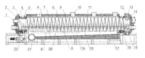
- FIG. 1 is the on-state cutaway view of the example 8 of this invention.
- This example includes the outer cylinder and the internal cylinder.
- the outer cylinder has the heating mechanism, and this heating mechanism can be realized by using the following method: the outer cylinder is designed as two layers structure and the heat carrier is circulating between the two layers.
- the internal cylinder has the feeding inlet, the ash outlet and the oil-gas outlet, and the heating plates are alternately fixed in the internal cylinder. Furthermore, the heating plate uses the different material inlaid in the wall of the internal cylinder.
- the screw is fixed in the internal cylinder for pushing the raw material.
- the rest parts of this example adopt the present technology.
- This example includes the outer cylinder and the internal cylinder.
- the outer cylinder has the heating mechanism, and this heating mechanism can be the electric-heating mechanism, which is fixed in the outer cylinder.
- the internal cylinder has the feeding inlet, the ash outlet and the oil-gas outlet, and the heating plates are alternately fixed in the internal cylinder. Furthermore, the heating plate is set in the outer wall of the internal cylinder. The screw is fixed in the internal cylinder for pushing the raw material.
- the rest parts of this example adopt the present technology.
- This example includes the outer cylinder and the internal cylinder.
- the outer cylinder has the heating mechanism, and this heating mechanism can be realized by using the following method: the gas inlet and the smoke outlet are fixed in the outer cylinder, and the hot wind is passed into the outer cylinder through the hot-wind inlet for heating the internal cylinder.
- the internal cylinder has the feeding inlet, the ash outlet and the oil-gas outlet, and the annular heating plates are alternately fixed in the internal cylinder.
- the helical ribbon is fixed in the internal cylinder's inner wall for pushing the raw material.
- This example includes the outer cylinder and the internal cylinder.
- the outer cylinder has the heating mechanism, and this heating mechanism can be realized by using the following method: the gas inlet and the smoke outlet are fixed in the outer cylinder, and the air volume control board is also fixed in the outer cylinder.
- the internal cylinder has the feeding inlet, the ash outlet and the oil-gas outlet, and the spiral heating plates are alternately fixed in the internal cylinder. Furthermore, the heating plate is set in the outer wall of the internal cylinder.
- the helical ribbon is fixed in the internal cylinder for pushing the raw material.
- the lower part of the outer cylinder is the hot-wind tube with the gas inlet, and the foreside of the hot-wind tube is fixed with a set of air volume control boards following the outer cylinder's axes direction. Furthermore, the smoke outlets are distributed at the end of the outer cylinder.
- the heating mechanism is fixed in the internal cylinder, and this heating mechanism is the tube with the hot fluid (it can be gas or liquid) or the electric-heating mechanism.
- the heating mechanism of the internal cylinder is inclined to the bottom of the internal cylinder, which is closing to the cracking product.
- the internal cylinder can be fully heated.
- this example includes the bracket 17 , inside which hot-wind tube 19 is fixed, and hot-wind tube 19 has the wind inlet 21 .
- the outer cylinder 6 is fixed on the top of the bracket 17 , the outer cylinder 6 and the hot-wind tube 19 are encircled by the heat preservation layer 11 , and the outer cylinder 6 's bottom space is connected with the hot-wind tube 19 .
- a set of air volume control boards 20 are fixed in the hot-wind tube 19 following the axes direction of the outer cylinder 6 , and the foreside of every air volume control board 20 are fixed on the hot-wind tube 19 's sidewall through the axis.
- the smoke outlet 10 is fixed on the right top of the outer cylinder 6 .
- the internal cylinder 7 is fixed on the inside of the outer cylinder 6 , and the two ends of the internal cylinder 7 through the outer are fixed on the left and right shell cover by moving seal. Furthermore, the prolongation out of the outer cylinder 6 is connected with the power mechanism by the sprocket wheel 5 .
- the continuous helical heat plate 8 is fixed on the internal cylinder's outer surface of the internal cylinder 7 , which is fixed inside the outer cylinder 6 .
- the helical ribbon 9 is fixed in the internal cylinder 7 for pushing the raw material's movement from the left part to the right part, the cracking reaction will take place in this movement from left to right.
- the heat carrier fluid's heat tube 18 passes through the internal cylinder 7 , and the two ends of the tube are fixed on the two shell covers 3 and 12 .
- the heat tube 18 is inclining to the bottom of the internal cylinder 7 .
- the feeding inlet 1 is fixed on the left shell cover 3 , and it is on the top of the heat tube 18 .
- the lambdoidal feeding guide plates 2 are fixed on the feeding inlet 1 's inner end and the top of the heat tube 18 , and these feeding guide plates transport the raw material from the sides of the heat tube 18 to the internal cylinder 7 .
- the right shell cover 12 of this example has the smoke outlet 13 , the oil-gas outlet 14 and the ash outlet 15 .
- the raw material is added to the internal cylinder 7 through the feeding inlet 1 , and slides into the bottom of the internal cylinder 7 following the feeding guide plate 2 .
- the raw material moves from the left to the right in the helical ribbon 9 's operation.
- the hot wind is emitted into the outer cylinder 6 through the hot-wind tube 19 to heat the internal cylinder 7 via the outer cylinder's bottom placket, further, to heat the raw material in the heat plate 8 and the internal cylinder 7 .
- the heat plate will ensure the internal cylinder temperature's stabilization, while the raw material will be cracked in this process.
- the oil-gas produced in the cracking process is emitted through the oil-gas outlet, which is closed the right shell cover. Furthermore, the cracking product, such as carbon black, is discharged via the ash outlet.
- the raw material is continuously transported into the internal cylinder through the feeding inlet, while the products are continuously discharged via the oil-gas outlet and the ash outlet, thus realizes the continuous cracking of rubber.
Landscapes
- Chemical & Material Sciences (AREA)
- Engineering & Computer Science (AREA)
- Oil, Petroleum & Natural Gas (AREA)
- Organic Chemistry (AREA)
- Materials Engineering (AREA)
- Life Sciences & Earth Sciences (AREA)
- Combustion & Propulsion (AREA)
- Wood Science & Technology (AREA)
- Chemical Kinetics & Catalysis (AREA)
- General Chemical & Material Sciences (AREA)
- Processing Of Solid Wastes (AREA)
- Production Of Liquid Hydrocarbon Mixture For Refining Petroleum (AREA)
- Separation, Recovery Or Treatment Of Waste Materials Containing Plastics (AREA)
- Processing And Handling Of Plastics And Other Materials For Molding In General (AREA)
Applications Claiming Priority (4)
| Application Number | Priority Date | Filing Date | Title |
|---|---|---|---|
| CN2007101158987A CN101469081B (zh) | 2007-12-29 | 2007-12-29 | 工业连续化橡胶裂解器 |
| CN200710115898 | 2007-12-29 | ||
| CN200710115898.7 | 2007-12-29 | ||
| PCT/CN2007/003894 WO2009086655A1 (fr) | 2007-12-29 | 2007-12-29 | Appareillage de pyrolyse industriellement continu |
Publications (2)
| Publication Number | Publication Date |
|---|---|
| US20100282589A1 US20100282589A1 (en) | 2010-11-11 |
| US8764945B2 true US8764945B2 (en) | 2014-07-01 |
Family
ID=40826897
Family Applications (1)
| Application Number | Title | Priority Date | Filing Date |
|---|---|---|---|
| US12/735,315 Active 2030-01-19 US8764945B2 (en) | 2007-12-29 | 2007-12-29 | Industrial continuous cracking device of rubber |
Country Status (6)
| Country | Link |
|---|---|
| US (1) | US8764945B2 (fr) |
| EP (1) | EP2236582A4 (fr) |
| JP (1) | JP5291118B2 (fr) |
| CN (1) | CN101469081B (fr) |
| CA (1) | CA2728584C (fr) |
| WO (1) | WO2009086655A1 (fr) |
Cited By (1)
| Publication number | Priority date | Publication date | Assignee | Title |
|---|---|---|---|---|
| US11326106B2 (en) * | 2018-09-28 | 2022-05-10 | Niutech Environment Technology Corporation | Solid hazardous waste pyrolysis process and full-set equipment |
Families Citing this family (14)
| Publication number | Priority date | Publication date | Assignee | Title |
|---|---|---|---|---|
| CN104250557A (zh) * | 2013-06-26 | 2014-12-31 | 窦洪波 | 废有机物裂解反应器 |
| CN106190219B (zh) * | 2016-08-31 | 2018-08-07 | 广东新生环保科技股份有限公司 | 一种有机高分子废弃物料的分解方法 |
| CN108911458B (zh) * | 2018-08-13 | 2023-09-08 | 济南恒誉环保科技股份有限公司 | 一种油泥裂解装置 |
| CN109092865B (zh) * | 2018-09-28 | 2023-11-17 | 济南恒誉环保科技股份有限公司 | 一种固体危废裂解装置 |
| CN111073676A (zh) * | 2019-12-30 | 2020-04-28 | 济南恒誉环保科技股份有限公司 | 一种工业连续化同轴多腔裂解器 |
| CN112143509B (zh) * | 2020-09-11 | 2021-05-28 | 内蒙古汉生源科技有限公司 | 一种煤炭焦化处理方法 |
| CN112391183A (zh) * | 2020-12-14 | 2021-02-23 | 双星集团有限责任公司 | 一种新型废旧橡塑连续化内旋式双螺旋热裂解系统 |
| CN114653308A (zh) * | 2020-12-22 | 2022-06-24 | 北京汇潮云集科技有限公司 | 一种具有破碎功能的烘干设备及裂解系统 |
| CN114653309A (zh) * | 2020-12-22 | 2022-06-24 | 北京汇潮云集科技有限公司 | 一种烘干设备及裂解系统 |
| CN114713144A (zh) * | 2020-12-22 | 2022-07-08 | 北京汇潮云集科技有限公司 | 一种裂解设备 |
| CN114713138A (zh) * | 2020-12-22 | 2022-07-08 | 北京汇潮云集科技有限公司 | 一种先内后外加热式烘干设备及裂解系统 |
| WO2022233455A1 (fr) | 2021-05-07 | 2022-11-10 | Knauf Gips Kg | Panneau de gypse léger résistant à l'affaissement à haute température |
| CN113999546B (zh) * | 2021-10-09 | 2022-08-23 | 济南恒誉环保科技股份有限公司 | 一种裂解炭黑二次处理工艺及装置 |
| CN113862010A (zh) * | 2021-10-26 | 2021-12-31 | 北京新风航天装备有限公司 | 一种撬装式有机固废热解装置 |
Citations (3)
| Publication number | Priority date | Publication date | Assignee | Title |
|---|---|---|---|---|
| US1587256A (en) * | 1924-04-09 | 1926-06-01 | Foulk | Rotary oil-shale retort |
| US1748178A (en) * | 1923-10-12 | 1930-02-25 | Hume Walter Reginald | Rotary retort |
| CN101074384A (zh) * | 2007-04-28 | 2007-11-21 | 牛斌 | 回转式自动裂解工艺及裂解器 |
Family Cites Families (11)
| Publication number | Priority date | Publication date | Assignee | Title |
|---|---|---|---|---|
| CH113119A (fr) * | 1925-01-30 | 1926-02-16 | Emilien Bornand | Four. |
| JP3629045B2 (ja) * | 1994-08-22 | 2005-03-16 | 株式会社チサキ | 可燃固体のガス化装置 |
| JP3889124B2 (ja) * | 1997-08-08 | 2007-03-07 | 健 黒木 | 廃棄プラスチックの連続油化装置、廃棄プラスチックの連続油化方法 |
| JP2000292067A (ja) * | 1999-04-05 | 2000-10-20 | Ishikawajima Harima Heavy Ind Co Ltd | 外熱式キルン |
| CN2451587Y (zh) * | 2000-10-11 | 2001-10-03 | 贾卧龙 | 废塑料炼油反应釜 |
| CN2564575Y (zh) * | 2002-07-16 | 2003-08-06 | 上海绿人生态经济科技有限公司 | 具有螺旋气流导板的热裂解炉 |
| CN2671681Y (zh) * | 2003-11-18 | 2005-01-19 | 严绥 | 带有金属导热翅片熔盐夹套的反应釜 |
| KR100787958B1 (ko) * | 2004-09-25 | 2007-12-31 | 구재완 | 폐합성 고분자화합물의 연속식 열분해 시스템 |
| CN2878390Y (zh) * | 2006-04-07 | 2007-03-14 | 王新明 | 多功能全自动远程恒温供热废旧轮胎裂化装置 |
| CN1952045A (zh) * | 2006-09-29 | 2007-04-25 | 浙江大学 | 废旧钢丝胎料块连续热裂解的卧式回转圆筒结构裂解炉 |
| CN200995997Y (zh) * | 2007-01-31 | 2007-12-26 | 宜兴市昌华过滤器材有限公司 | 卧式推进裂解炉 |
-
2007
- 2007-12-29 CA CA2728584A patent/CA2728584C/fr active Active
- 2007-12-29 US US12/735,315 patent/US8764945B2/en active Active
- 2007-12-29 EP EP07855894A patent/EP2236582A4/fr not_active Ceased
- 2007-12-29 CN CN2007101158987A patent/CN101469081B/zh active Active
- 2007-12-29 JP JP2010539987A patent/JP5291118B2/ja not_active Expired - Fee Related
- 2007-12-29 WO PCT/CN2007/003894 patent/WO2009086655A1/fr not_active Ceased
Patent Citations (3)
| Publication number | Priority date | Publication date | Assignee | Title |
|---|---|---|---|---|
| US1748178A (en) * | 1923-10-12 | 1930-02-25 | Hume Walter Reginald | Rotary retort |
| US1587256A (en) * | 1924-04-09 | 1926-06-01 | Foulk | Rotary oil-shale retort |
| CN101074384A (zh) * | 2007-04-28 | 2007-11-21 | 牛斌 | 回转式自动裂解工艺及裂解器 |
Cited By (1)
| Publication number | Priority date | Publication date | Assignee | Title |
|---|---|---|---|---|
| US11326106B2 (en) * | 2018-09-28 | 2022-05-10 | Niutech Environment Technology Corporation | Solid hazardous waste pyrolysis process and full-set equipment |
Also Published As
| Publication number | Publication date |
|---|---|
| US20100282589A1 (en) | 2010-11-11 |
| JP5291118B2 (ja) | 2013-09-18 |
| CN101469081B (zh) | 2012-07-04 |
| CA2728584A1 (fr) | 2009-07-16 |
| CA2728584C (fr) | 2012-10-23 |
| JP2011509319A (ja) | 2011-03-24 |
| EP2236582A1 (fr) | 2010-10-06 |
| EP2236582A4 (fr) | 2013-03-27 |
| CN101469081A (zh) | 2009-07-01 |
| WO2009086655A1 (fr) | 2009-07-16 |
Similar Documents
| Publication | Publication Date | Title |
|---|---|---|
| US8764945B2 (en) | Industrial continuous cracking device of rubber | |
| EP2233439B1 (fr) | Equipement industriel pour le craquage en continu de matière plastique | |
| CN106811217B (zh) | 一种生物质气化设备及生物质气化工艺 | |
| CN107022362B (zh) | 生物质或有机垃圾转化设备及转化工艺 | |
| CN202393244U (zh) | 一种高效物料预热输送装置 | |
| CN212512643U (zh) | 一种热交换面积可变的上升管换热器 | |
| CN110256876A (zh) | 一种裂解炉及裂解系统 | |
| CN106430184A (zh) | 一种化学法制活性炭的多层链板式活化炉 | |
| CN203095995U (zh) | 一种有机物质微波热裂解装置 | |
| CN201254557Y (zh) | 工业连续化橡胶裂解器 | |
| CN221619467U (zh) | 一种粉末活性炭连续化微波再生装置 | |
| CN103450913B (zh) | 一种垃圾热裂解机 | |
| CN207646040U (zh) | 工业连续化污油泥热分解撬装设备 | |
| CN206094897U (zh) | 一种煅烧炉 | |
| CN116808974A (zh) | 一种具有多层温度可控功能的氯化用化工反应器 | |
| CN222864943U (zh) | 一种高效热解生物炭热回收装置 | |
| CN105542831A (zh) | 胶粒反应裂解釜 | |
| CN111486737B (zh) | 一种热交换面积可变的上升管换热器 | |
| CN223538036U (zh) | 一种轻烧氧化镁生产用回转窑 | |
| CN222086784U (zh) | 一种卧式汽封冷却器 | |
| CN221028241U (zh) | 微波热解炉 | |
| CN222789260U (zh) | 一种节能连续式微波流化活性炭再生活化设备 | |
| CN219488586U (zh) | 一种pe管加工用上料设备 | |
| CN220242162U (zh) | 一种钢丝网骨架聚乙烯复合管道的冷却设备 | |
| CN115790186B (zh) | 一种余热利用设备及其使用方法 |
Legal Events
| Date | Code | Title | Description |
|---|---|---|---|
| STCF | Information on status: patent grant |
Free format text: PATENTED CASE |
|
| AS | Assignment |
Owner name: NIUTECH ENVIRONMENT TECHNOLOGY CORPORATION, CHINA Free format text: ASSIGNMENT OF ASSIGNORS INTEREST;ASSIGNOR:NIU, BIN;REEL/FRAME:037471/0345 Effective date: 20160108 |
|
| FPAY | Fee payment |
Year of fee payment: 4 |
|
| MAFP | Maintenance fee payment |
Free format text: PAYMENT OF MAINTENANCE FEE, 8TH YR, SMALL ENTITY (ORIGINAL EVENT CODE: M2552); ENTITY STATUS OF PATENT OWNER: SMALL ENTITY Year of fee payment: 8 |
|
| MAFP | Maintenance fee payment |
Free format text: PAYMENT OF MAINTENANCE FEE, 12TH YR, SMALL ENTITY (ORIGINAL EVENT CODE: M2553); ENTITY STATUS OF PATENT OWNER: SMALL ENTITY Year of fee payment: 12 |