US8790576B2 - Vessel treatment machine - Google Patents
Vessel treatment machine Download PDFInfo
- Publication number
- US8790576B2 US8790576B2 US12/920,896 US92089609A US8790576B2 US 8790576 B2 US8790576 B2 US 8790576B2 US 92089609 A US92089609 A US 92089609A US 8790576 B2 US8790576 B2 US 8790576B2
- Authority
- US
- United States
- Prior art keywords
- chamber
- control valve
- supply line
- gas
- liquid
- Prior art date
- Legal status (The legal status is an assumption and is not a legal conclusion. Google has not performed a legal analysis and makes no representation as to the accuracy of the status listed.)
- Expired - Fee Related, expires
Links
Images


Classifications
-
- A—HUMAN NECESSITIES
- A61—MEDICAL OR VETERINARY SCIENCE; HYGIENE
- A61L—METHODS OR APPARATUS FOR STERILISING MATERIALS OR OBJECTS IN GENERAL; DISINFECTION, STERILISATION OR DEODORISATION OF AIR; CHEMICAL ASPECTS OF BANDAGES, DRESSINGS, ABSORBENT PADS OR SURGICAL ARTICLES; MATERIALS FOR BANDAGES, DRESSINGS, ABSORBENT PADS OR SURGICAL ARTICLES
- A61L2/00—Disinfection or sterilisation of materials or objects, in general; Accessories therefor
- A61L2/16—Disinfection or sterilisation of materials or objects, in general; Accessories therefor using chemical substances
- A61L2/18—Liquid substances
- A61L2/186—Peroxide solutions
-
- A—HUMAN NECESSITIES
- A61—MEDICAL OR VETERINARY SCIENCE; HYGIENE
- A61L—METHODS OR APPARATUS FOR STERILISING MATERIALS OR OBJECTS IN GENERAL; DISINFECTION, STERILISATION OR DEODORISATION OF AIR; CHEMICAL ASPECTS OF BANDAGES, DRESSINGS, ABSORBENT PADS OR SURGICAL ARTICLES; MATERIALS FOR BANDAGES, DRESSINGS, ABSORBENT PADS OR SURGICAL ARTICLES
- A61L2/00—Disinfection or sterilisation of materials or objects, in general; Accessories therefor
- A61L2/16—Disinfection or sterilisation of materials or objects, in general; Accessories therefor using chemical substances
- A61L2/20—Gaseous substances, e.g. vapours
- A61L2/208—Hydrogen peroxide
-
- A—HUMAN NECESSITIES
- A61—MEDICAL OR VETERINARY SCIENCE; HYGIENE
- A61L—METHODS OR APPARATUS FOR STERILISING MATERIALS OR OBJECTS IN GENERAL; DISINFECTION, STERILISATION OR DEODORISATION OF AIR; CHEMICAL ASPECTS OF BANDAGES, DRESSINGS, ABSORBENT PADS OR SURGICAL ARTICLES; MATERIALS FOR BANDAGES, DRESSINGS, ABSORBENT PADS OR SURGICAL ARTICLES
- A61L2/00—Disinfection or sterilisation of materials or objects, in general; Accessories therefor
- A61L2/24—Apparatus using programmed or automatic operation
-
- B—PERFORMING OPERATIONS; TRANSPORTING
- B01—PHYSICAL OR CHEMICAL PROCESSES OR APPARATUS IN GENERAL
- B01D—SEPARATION
- B01D27/00—Cartridge filters of the throw-away type
- B01D27/08—Construction of the casing
-
- B—PERFORMING OPERATIONS; TRANSPORTING
- B01—PHYSICAL OR CHEMICAL PROCESSES OR APPARATUS IN GENERAL
- B01D—SEPARATION
- B01D27/00—Cartridge filters of the throw-away type
- B01D27/10—Safety devices, e.g. by-passes
- B01D27/103—Bypass or safety valves
-
- B—PERFORMING OPERATIONS; TRANSPORTING
- B01—PHYSICAL OR CHEMICAL PROCESSES OR APPARATUS IN GENERAL
- B01D—SEPARATION
- B01D27/00—Cartridge filters of the throw-away type
- B01D27/10—Safety devices, e.g. by-passes
- B01D27/106—Anti-leakage or anti-return valves
-
- B—PERFORMING OPERATIONS; TRANSPORTING
- B01—PHYSICAL OR CHEMICAL PROCESSES OR APPARATUS IN GENERAL
- B01D—SEPARATION
- B01D35/00—Filtering devices having features not specifically covered by groups B01D24/00 - B01D33/00, or for applications not specifically covered by groups B01D24/00 - B01D33/00; Auxiliary devices for filtration; Filter housing constructions
- B01D35/30—Filter housing constructions
- B01D35/306—Filter mounting adapter
-
- B—PERFORMING OPERATIONS; TRANSPORTING
- B65—CONVEYING; PACKING; STORING; HANDLING THIN OR FILAMENTARY MATERIAL
- B65B—MACHINES, APPARATUS OR DEVICES FOR, OR METHODS OF, PACKAGING ARTICLES OR MATERIALS; UNPACKING
- B65B55/00—Preserving, protecting or purifying packages or package contents in association with packaging
- B65B55/02—Sterilising, e.g. of complete packages
- B65B55/04—Sterilising wrappers or receptacles prior to, or during, packaging
- B65B55/10—Sterilising wrappers or receptacles prior to, or during, packaging by liquids or gases
-
- A—HUMAN NECESSITIES
- A61—MEDICAL OR VETERINARY SCIENCE; HYGIENE
- A61L—METHODS OR APPARATUS FOR STERILISING MATERIALS OR OBJECTS IN GENERAL; DISINFECTION, STERILISATION OR DEODORISATION OF AIR; CHEMICAL ASPECTS OF BANDAGES, DRESSINGS, ABSORBENT PADS OR SURGICAL ARTICLES; MATERIALS FOR BANDAGES, DRESSINGS, ABSORBENT PADS OR SURGICAL ARTICLES
- A61L2103/00—Materials or objects being the target of disinfection or sterilisation
- A61L2103/23—Containers other than laboratory or medical, e.g. bottles or mail
-
- B—PERFORMING OPERATIONS; TRANSPORTING
- B01—PHYSICAL OR CHEMICAL PROCESSES OR APPARATUS IN GENERAL
- B01D—SEPARATION
- B01D2201/00—Details relating to filtering apparatus
- B01D2201/34—Seals or gaskets for filtering elements
Definitions
- the invention relates to a vessel treatment machine for sterilizing containers by means of a sterilizing liquid, said vessel treatment machine having at least one liquid supply line and one or more gas supply lines, in addition at least one mixing chamber for producing a liquid/gas mixture, and at least one valve in the liquid supply line.
- Such a vessel treatment machine is described in the main in WO 03/030950 A1. Similar developments are the object of DE 10 2004 029 803 B4.
- the vessel treatment machine is routinely such a machine that is used in the beverage industry, i.e. as is used when filling beverages into bottles, cans or general containers that are made, for example, of plastics material, metal, glass etc.
- liquid hydrogen peroxide H 2 O 2 is routinely added as sterilizing liquid in a finely atomized form to an air flow in the mixing chamber. Subsequently, said liquid/gas mixture or hydrogen peroxide/air mixture may be supplied to an evaporator in which the still liquid H 2 O 2 is completely evaporated.
- the perfect sterilization of containers presupposes that the sterilizing liquid is made available in a properly metered manner. This occurs in the majority of cases with the aid of the at least one valve present in the liquid supply line.
- the problem that arises in this case is that the amount of liquid forwarded by the valve, for example, to an atomizing device can vary from case to case. Said varying liquid amount can be explained by the sterilizing liquid that remains in the valve from one discharge cycle to another at a treatment head. Over and above this, possible additional so-called “dead amounts” in a supply line from the valve to the mixing chamber or as far as the atomiser have to be taken into consideration.—This is where the invention fits in.
- the technical problem underlying the invention is to develop further a vessel treatment machine for sterilizing containers by means of a sterilizing liquid such that the sterilizing liquid is available in precisely meterable and reproducible amounts inside the mixing chamber.
- the mixing chamber and an outlet-side valve chamber of the valve coincide in an operative manner.
- the obligatory valve chamber at the outlet of the valve in the liquid supply line is used at the same time as a mixing chamber, i.e. for producing the liquid/gas mixture.
- the gas entering the mixing chamber or the valve chamber is automatically responsible for ensuring that the valve chamber is flushed, as it were, at the desired mixing ratio.
- the gas supply line for the supply of the gas normally opens out directly into the outlet-side valve chamber. I.e. the valve chamber is used for atomizing the liquid/gas mixture and is thus emptied after each stroke.
- Such a stroke corresponds to the necessary amount of liquid and gas that is necessary in most cases for the treatment of one container.
- the sterilizing liquid and the gas are supplied under pressure and the gas supply line can also be provided with a valve, it is possible by means of corresponding actuation of the valves to provide for the respective production of the liquid/gas mixture inside the mixing chamber or respectively valve chamber.
- Said liquid/gas mixture is then supplied to the treatment head, in which, as a rule, the already described evaporation operation and consequently the activation of the sterilizing liquid is effected.
- the activated sterilizing liquid or the mixture is finally blown into the container. This completes one stroke or operating stroke.
- the metering operation takes places completely inside the outlet-side valve chamber of the valve representing the mixing chamber in the liquid supply line, the metering or the metering operation is separated from the evaporation operation and consequently is not time-critical.
- the metering amount for the sterilizing liquid can be predetermined in a particularly sensitive manner, for example in terms of control. It is always guaranteed that the liquid/gas mixture subsequently leaving the outlet-side valve chamber or mixing chamber is adapted individually to the container to be treated.
- the detail of this can be effected in such a manner that a valve body inside the valve in the liquid supply line opens an opening to a greater or lesser extent between an inlet-side valve chamber and the outlet-side valve chamber.
- the amount of sterilizing liquid metered into the outlet-side valve chamber can be predetermined precisely in terms of control. This occurs until the amount of sterilizing liquid present in this manner in the outlet-side valve chamber is sufficient for treating the associated container and for the subsequent atomization with the aid of the gas.
- valve body between the two valve chambers may then be closed and subsequently the valve in the gas supply line can be opened in order to atomize the amount of sterilizing liquid present inside the outlet-side valve chamber. Because this operation takes place directly in the outlet-side valve chamber, which functions at the same time as a mixing chamber, it ensures that, in the case of the atomizing operation described, all the liquid constituents of the sterilizing liquid enter into the liquid/gas mixture. Any dead amounts as in the prior art are not observed.
- the outlet-side valve chamber of the valve located in the liquid supply line or respectively the control valve directly to a treatment head.
- the liquid/gas mixture generated in the outlet-side valve chamber can be supplied to an additional second mixing chamber, which is then connected, in its turn, to the treatment head.
- the mixing operation takes place in two stages, initially by the liquid/gas mixture being produced in the outlet-side valve chamber or first mixing chamber and then said liquid/gas mixture being transferred into an additional second mixing chamber, which is (also) acted upon with an additional second gas supply line.
- the additional second mixing chamber is supplied by the additional second gas supply line and a chamber supply line, which connects the first mixing chamber or outlet-side valve chamber to the second mixing chamber.
- the gas supply line is provided with a Venturi nozzle or generally with a nozzle on the inlet side of the (respective) mixing chamber.
- the valve in the gas supply line is also a control valve, that is a type of valve where the position of a valve body can be detected and in terms of control can be adjusted such that precisely the desired amount of metered gas or metered liquid (with the control valve in the liquid supply line) leaves the valve.
- the sterilizing liquid is liquid hydrogen peroxide, which is, however, not to be seen as compulsory.
- Sterile air is used predominantly as the gas, that is air that has been sterilized beforehand.
- An object of the invention is also a method for sterilizing containers in accordance with Claim 10 . The method described, in this case, can be accomplished in the vessel treatment machine explained in detail. However, this is not compulsory.
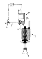
- FIG. 1 shows a first development of a vessel treatment machine according to the invention, reduced to the components essential to the invention and
- FIG. 2 shows a variant of the object in FIG. 1 .
- a vessel treatment machine which is used for sterilizing containers 1 is represented in the Figures.
- the container 1 just suggested in FIG. 1 , is a plastic PET bottle, which is obviously not to be seen as limiting.
- the sterilization is effected with the aid of a liquid/gas mixture, which is to be activated in a container head 2 , as is described in detail in DE 10 2004 029 803 B4.
- the container head 2 is provided, for example, with a heat exchanger, which is responsible for ensuring that the sterilizing liquid in the case in example is activated.
- the sterilizing liquid in reality in the present case is liquid hydrogen peroxide but this is not compulsory, said hydrogen peroxide being supplied via a liquid supply line 3 .
- Said sterilizing liquid or the liquid hydrogen peroxide is mixed with a gas (sterile air), which is supplied by way of a gas supply line 4 .
- a valve 5 Inside the liquid supply line 3 there is a valve 5 , which is in the form of a control valve.
- the gas supply line 4 also has a valve 6 , which is also in the form of a control valve.
- the two control valves 5 , 6 are connected to a common control unit 7 , which interrogates the position of their respective valve body in order to make available, in terms of control, a metered amount of sterilizing liquid on the outlet side of the valve 5 and furthermore a metered amount of gas on the outlet-side of the valve 6 .
- the gas is sterile air but this is not compulsory.
- valve or control valve 5 is provided with an inlet-side valve chamber 7 a and an outlet-side valve chamber 7 b , which are separated from one another by a valve body.
- the amount of sterilizing liquid inside the outlet-side valve chamber 7 b is predetermined—as described—in terms of control that is checked and predetermined by means of the control unit 7 .
- the valve body is generally closed and the valve 6 subsequently opened.
- the outlet-side valve chamber 7 b assumes the function of a mixing chamber 7 b for producing the liquid/gas mixture or for the atomization of the sterilizing liquid in the interior of the outlet-side valve chamber 7 b with the aid of the supplied gas. I.e. the mixing chamber 7 b and the outlet-side valve chamber 7 b coincide in an operative manner. It can be recognized that within the framework of the variant in FIG. 1 , the outlet-side valve chamber or mixing chamber 7 b is connected directly to the treatment head, namely by means of an output line 8 . Contrary to this, in the case of the variant in FIG. 2 an additional mixing chamber 9 is realized.
- the gas supply line 4 is divided after the Venturi 6 into two separate gas supply lines 4 a , 4 b , which open out into the respective mixing chambers 7 b or respectively 9 in the case of the variant in FIG. 2 .
- the mixing chamber 7 b or outlet-side valve chamber 7 b of the valve 5 assumes the function of a first mixing chamber 7 b
- the additional mixing chamber 9 operates as a second mixing chamber.
- the liquid/gas mixture generated inside the first mixing chamber 7 b is supplied via a chamber supply line 10 into the second mixing chamber 9 and here experiences another mixing operation such that the additional gas supply line 4 b is connected to the second mixing chamber 9 .
- a Venturi nozzle 11 on the inlet side of the second mixing chamber 9 ensures that the gas supplied via the gas supply line 4 b into the mixing chamber 9 experiences acceleration such that the atomization in the second mixing chamber 9 is intensified.
- the second mixing chamber 9 is connected directly to the treatment head 2 , which is obviously not to be seen as compulsory.
- the treatment head 2 can itself be a component of a carousel-type machine or a linear machine, as is known in general.
- the sterilizing liquid in addition utilizes the natural gradient inside the liquid supply line 3 because the flow direction of the sterilizing liquid follows gravity. This means that optimum degassing of the sterilizing liquid can be achieved before said sterilizing liquid is mixed with the gas in the mixing chamber or first mixing chamber 7 b . This guarantees that the liquid/gas mixture is composed in practice of only the two constituents—the sterilizing liquid and the gas (sterile air).
Landscapes
- Chemical & Material Sciences (AREA)
- Chemical Kinetics & Catalysis (AREA)
- Health & Medical Sciences (AREA)
- Epidemiology (AREA)
- Life Sciences & Earth Sciences (AREA)
- Animal Behavior & Ethology (AREA)
- General Health & Medical Sciences (AREA)
- Public Health (AREA)
- Veterinary Medicine (AREA)
- General Chemical & Material Sciences (AREA)
- Engineering & Computer Science (AREA)
- Mechanical Engineering (AREA)
- Apparatus For Disinfection Or Sterilisation (AREA)
- Crushing And Grinding (AREA)
- Electrical Discharge Machining, Electrochemical Machining, And Combined Machining (AREA)
- Crystals, And After-Treatments Of Crystals (AREA)
- Nozzles (AREA)
Applications Claiming Priority (4)
| Application Number | Priority Date | Filing Date | Title |
|---|---|---|---|
| DE102008015675 | 2008-03-25 | ||
| DE102008015675A DE102008015675A1 (de) | 2008-03-25 | 2008-03-25 | Gefäßbehandlungsmaschine |
| DE102008015675.2 | 2008-03-25 | ||
| PCT/EP2009/001697 WO2009118096A1 (de) | 2008-03-25 | 2009-03-10 | Gefässbehandlungsmaschine |
Publications (2)
| Publication Number | Publication Date |
|---|---|
| US20110020176A1 US20110020176A1 (en) | 2011-01-27 |
| US8790576B2 true US8790576B2 (en) | 2014-07-29 |
Family
ID=40674946
Family Applications (1)
| Application Number | Title | Priority Date | Filing Date |
|---|---|---|---|
| US12/920,896 Expired - Fee Related US8790576B2 (en) | 2008-03-25 | 2009-03-10 | Vessel treatment machine |
Country Status (6)
| Country | Link |
|---|---|
| US (1) | US8790576B2 (de) |
| EP (1) | EP2262544B1 (de) |
| AT (1) | ATE520423T1 (de) |
| DE (1) | DE102008015675A1 (de) |
| PL (1) | PL2262544T3 (de) |
| WO (1) | WO2009118096A1 (de) |
Cited By (3)
| Publication number | Priority date | Publication date | Assignee | Title |
|---|---|---|---|---|
| US10905786B2 (en) | 2017-03-27 | 2021-02-02 | Regeneron Pharmaceuticals, Inc. | Sterilisation method |
| USD1116103S1 (en) | 2019-06-05 | 2026-03-03 | Regeneron Pharmaceuticals, Inc. | Dose delivery device |
| USD1120314S1 (en) | 2022-11-30 | 2026-03-24 | Regeneron Pharmaceuticals, Inc. | Dose delivery device |
Families Citing this family (2)
| Publication number | Priority date | Publication date | Assignee | Title |
|---|---|---|---|---|
| JP6473057B2 (ja) * | 2015-07-23 | 2019-02-20 | 三菱重工機械システム株式会社 | 殺菌剤の気化方法及び気化装置 |
| US10287369B2 (en) * | 2017-04-24 | 2019-05-14 | Chevron Phillips Chemical Company Lp | Methods of preparing a catalyst |
Citations (12)
| Publication number | Priority date | Publication date | Assignee | Title |
|---|---|---|---|---|
| DE1566670A1 (de) | 1967-06-24 | 1970-04-30 | Medizintechnik Leipzig Veb | Verdampfer fuer Narkosegeraete mit bei normaler Temperatur fluessigen Narkosemitteln |
| DE3809852A1 (de) | 1988-03-24 | 1989-10-05 | Seitz Enzinger Noll Masch | Verfahren zum aseptischen bzw. sterilen abfuellen von fluessigem fuellgut in behaelter sowie vorrichtung zum durchfuehren dieses verfahrens |
| EP0353486A1 (de) | 1988-07-22 | 1990-02-07 | ROBINO & GALANDRINO S.P.A. | Vorrichtung zum Dosieren, insbesondere zum Dosieren von Sterilisationsmitteln zum Sterilisieren von Flaschen, Behältern, und so weiter |
| EP0427051A1 (de) | 1989-11-07 | 1991-05-15 | Tetra Laval Holdings & Finance SA | Verfahren zur Produktion eines gasförmigen Fluidums, das Wasserstoffperoxyd enthält |
| US6120730A (en) | 1998-06-26 | 2000-09-19 | Tetra Laval Holdings & Finance, Sa | Heat and hydrogen peroxide gas sterilization of container |
| WO2001068266A1 (de) | 2000-03-17 | 2001-09-20 | Wilfried Wiegers | Vorrichtung zum austragen eines verwirbelten gemisches aus einer flüssigkeit, der ggf. ein wirkstoff zugegeben ist und gas |
| WO2002074351A1 (de) | 2001-03-20 | 2002-09-26 | Rüdiger Haaga GmbH | Verfahren zum sterilisieren von behältern |
| US6478240B1 (en) * | 1998-04-13 | 2002-11-12 | Nauchno-Issledovatelsky Institut Nizkikh Temperatur Pri Mai | Device for generating a gas-droplet stream and valve |
| WO2003030950A1 (en) | 2001-10-05 | 2003-04-17 | Pepsico, Inc. | High-speed, low-temperature sterilization and sanitization apparatus and method |
| GB2395904A (en) * | 2002-12-03 | 2004-06-09 | Bosch Gmbh Robert | Apparatus for volatilising a decontamination agent |
| DE10346843A1 (de) | 2002-12-03 | 2004-06-24 | Robert Bosch Gmbh | Vorrichtung zum Vergasen eines Dekontaminationsmittels |
| DE102004029803A1 (de) | 2004-06-19 | 2006-01-12 | Khs Maschinen- Und Anlagenbau Ag | Gefäßbehandlungsmaschine zur Sterilisation von Behältern mittels H2O2 |
-
2008
- 2008-03-25 DE DE102008015675A patent/DE102008015675A1/de not_active Ceased
-
2009
- 2009-03-10 EP EP09726079A patent/EP2262544B1/de not_active Not-in-force
- 2009-03-10 PL PL09726079T patent/PL2262544T3/pl unknown
- 2009-03-10 WO PCT/EP2009/001697 patent/WO2009118096A1/de not_active Ceased
- 2009-03-10 US US12/920,896 patent/US8790576B2/en not_active Expired - Fee Related
- 2009-03-10 AT AT09726079T patent/ATE520423T1/de active
Patent Citations (14)
| Publication number | Priority date | Publication date | Assignee | Title |
|---|---|---|---|---|
| DE1566670A1 (de) | 1967-06-24 | 1970-04-30 | Medizintechnik Leipzig Veb | Verdampfer fuer Narkosegeraete mit bei normaler Temperatur fluessigen Narkosemitteln |
| DE3809852A1 (de) | 1988-03-24 | 1989-10-05 | Seitz Enzinger Noll Masch | Verfahren zum aseptischen bzw. sterilen abfuellen von fluessigem fuellgut in behaelter sowie vorrichtung zum durchfuehren dieses verfahrens |
| US5163487A (en) | 1988-03-24 | 1992-11-17 | Seitz Enzinger Noll Maschinenbau Aktiengesellschaft | Method and apparatus for dispensing a liquid into containers in an aseptic or sterile manner |
| EP0353486A1 (de) | 1988-07-22 | 1990-02-07 | ROBINO & GALANDRINO S.P.A. | Vorrichtung zum Dosieren, insbesondere zum Dosieren von Sterilisationsmitteln zum Sterilisieren von Flaschen, Behältern, und so weiter |
| EP0427051A1 (de) | 1989-11-07 | 1991-05-15 | Tetra Laval Holdings & Finance SA | Verfahren zur Produktion eines gasförmigen Fluidums, das Wasserstoffperoxyd enthält |
| US6478240B1 (en) * | 1998-04-13 | 2002-11-12 | Nauchno-Issledovatelsky Institut Nizkikh Temperatur Pri Mai | Device for generating a gas-droplet stream and valve |
| US6120730A (en) | 1998-06-26 | 2000-09-19 | Tetra Laval Holdings & Finance, Sa | Heat and hydrogen peroxide gas sterilization of container |
| WO2001068266A1 (de) | 2000-03-17 | 2001-09-20 | Wilfried Wiegers | Vorrichtung zum austragen eines verwirbelten gemisches aus einer flüssigkeit, der ggf. ein wirkstoff zugegeben ist und gas |
| DE10013150A1 (de) | 2000-03-17 | 2001-10-04 | Wilfried Wiegers | Vorrichtung zum Austragen eines verwirbelten Gemisches aus einer Flüssigkeit, der ggf. ein Wirkstoff zugegeben ist und Gas |
| WO2002074351A1 (de) | 2001-03-20 | 2002-09-26 | Rüdiger Haaga GmbH | Verfahren zum sterilisieren von behältern |
| WO2003030950A1 (en) | 2001-10-05 | 2003-04-17 | Pepsico, Inc. | High-speed, low-temperature sterilization and sanitization apparatus and method |
| GB2395904A (en) * | 2002-12-03 | 2004-06-09 | Bosch Gmbh Robert | Apparatus for volatilising a decontamination agent |
| DE10346843A1 (de) | 2002-12-03 | 2004-06-24 | Robert Bosch Gmbh | Vorrichtung zum Vergasen eines Dekontaminationsmittels |
| DE102004029803A1 (de) | 2004-06-19 | 2006-01-12 | Khs Maschinen- Und Anlagenbau Ag | Gefäßbehandlungsmaschine zur Sterilisation von Behältern mittels H2O2 |
Cited By (4)
| Publication number | Priority date | Publication date | Assignee | Title |
|---|---|---|---|---|
| US10905786B2 (en) | 2017-03-27 | 2021-02-02 | Regeneron Pharmaceuticals, Inc. | Sterilisation method |
| US10918754B2 (en) | 2017-03-27 | 2021-02-16 | Regeneron Pharmaceuticals, Inc. | Sterilisation method |
| USD1116103S1 (en) | 2019-06-05 | 2026-03-03 | Regeneron Pharmaceuticals, Inc. | Dose delivery device |
| USD1120314S1 (en) | 2022-11-30 | 2026-03-24 | Regeneron Pharmaceuticals, Inc. | Dose delivery device |
Also Published As
| Publication number | Publication date |
|---|---|
| ATE520423T1 (de) | 2011-09-15 |
| EP2262544A1 (de) | 2010-12-22 |
| WO2009118096A1 (de) | 2009-10-01 |
| EP2262544B1 (de) | 2011-08-17 |
| US20110020176A1 (en) | 2011-01-27 |
| DE102008015675A1 (de) | 2009-10-01 |
| PL2262544T3 (pl) | 2012-01-31 |
Similar Documents
| Publication | Publication Date | Title |
|---|---|---|
| US8790576B2 (en) | Vessel treatment machine | |
| CN1222323C (zh) | 用于包装容器杀菌的方法和装置 | |
| US9078943B2 (en) | Hydrogen peroxide supply for sterilization of a container, including a bypass arrangement for recirculation of hydrogen peroxide | |
| US6562281B1 (en) | Method for making sterilized plastic containers, and installation therefor | |
| JP4885951B2 (ja) | プリフォームを殺菌消毒する方法、及びこれらのプリフォームから殺菌消毒されたボトルを製造するための設備 | |
| US6736379B1 (en) | Device for generating an aerosol | |
| EP2049275B1 (de) | Verfahren zur sterilisation von reinräumen für die behandlung und/oder das füllen und verschliessen von behältern | |
| JP4861644B2 (ja) | 瓶等の容器を殺菌する方法及びこの方法を実施する消毒器 | |
| JP6498637B2 (ja) | 容器の殺菌に用いられる3流体ノズル | |
| US11077602B2 (en) | Blow-molding machine and method of sterilizing the same | |
| TWI405625B (zh) | 容器殺菌和洗淨方法及裝置 | |
| CN110248888B (zh) | 饮料无菌填充系统以及碳酸饮料无菌填充系统 | |
| JP2010132358A (ja) | Petボトルの殺菌方法及び殺菌装置 | |
| EP3412623B1 (de) | Reinigungsverfahren | |
| WO2015137480A1 (ja) | 容器の殺菌方法及び装置 | |
| DK2214724T3 (en) | Equipment and method for the preparation of a sterilant gas mixture | |
| US667491A (en) | Atomizer. | |
| JP2009166900A (ja) | Pet製ボトルの殺菌方法及び装置 | |
| JP7660106B2 (ja) | 充填機用の粒子除去装置及び粒子除去方法 | |
| JP2007039137A (ja) | Pet製ボトルの殺菌方法及び装置 | |
| JPH02172564A (ja) | 殺菌液スプレーの検出方法 |
Legal Events
| Date | Code | Title | Description |
|---|---|---|---|
| AS | Assignment |
Owner name: KHS GMBH, GERMANY Free format text: ASSIGNMENT OF ASSIGNORS INTEREST;ASSIGNORS:BAUER, EVA;BEHRENDT, FRANK PETER;KIEFER, MARGIT;AND OTHERS;SIGNING DATES FROM 20100923 TO 20101027;REEL/FRAME:025354/0630 |
|
| FEPP | Fee payment procedure |
Free format text: PAYOR NUMBER ASSIGNED (ORIGINAL EVENT CODE: ASPN); ENTITY STATUS OF PATENT OWNER: LARGE ENTITY |
|
| STCF | Information on status: patent grant |
Free format text: PATENTED CASE |
|
| MAFP | Maintenance fee payment |
Free format text: PAYMENT OF MAINTENANCE FEE, 4TH YEAR, LARGE ENTITY (ORIGINAL EVENT CODE: M1551) Year of fee payment: 4 |
|
| FEPP | Fee payment procedure |
Free format text: MAINTENANCE FEE REMINDER MAILED (ORIGINAL EVENT CODE: REM.); ENTITY STATUS OF PATENT OWNER: LARGE ENTITY |
|
| LAPS | Lapse for failure to pay maintenance fees |
Free format text: PATENT EXPIRED FOR FAILURE TO PAY MAINTENANCE FEES (ORIGINAL EVENT CODE: EXP.); ENTITY STATUS OF PATENT OWNER: LARGE ENTITY |
|
| STCH | Information on status: patent discontinuation |
Free format text: PATENT EXPIRED DUE TO NONPAYMENT OF MAINTENANCE FEES UNDER 37 CFR 1.362 |
|
| FP | Lapsed due to failure to pay maintenance fee |
Effective date: 20220729 |