US8884489B2 - Motor - Google Patents
Motor Download PDFInfo
- Publication number
- US8884489B2 US8884489B2 US13/499,665 US201013499665A US8884489B2 US 8884489 B2 US8884489 B2 US 8884489B2 US 201013499665 A US201013499665 A US 201013499665A US 8884489 B2 US8884489 B2 US 8884489B2
- Authority
- US
- United States
- Prior art keywords
- base unit
- phase
- slot
- flat conductor
- coil
- Prior art date
- Legal status (The legal status is an assumption and is not a legal conclusion. Google has not performed a legal analysis and makes no representation as to the accuracy of the status listed.)
- Expired - Fee Related, expires
Links
Images



Classifications
-
- H—ELECTRICITY
- H02—GENERATION; CONVERSION OR DISTRIBUTION OF ELECTRIC POWER
- H02K—DYNAMO-ELECTRIC MACHINES
- H02K3/00—Details of windings
- H02K3/04—Windings characterised by the conductor shape, form or construction, e.g. with bar conductors
-
- H02K15/045—
-
- H—ELECTRICITY
- H02—GENERATION; CONVERSION OR DISTRIBUTION OF ELECTRIC POWER
- H02K—DYNAMO-ELECTRIC MACHINES
- H02K15/00—Processes or apparatus specially adapted for manufacturing, assembling, maintaining or repairing of dynamo-electric machines
- H02K15/04—Processes or apparatus specially adapted for manufacturing, assembling, maintaining or repairing of dynamo-electric machines of windings prior to their mounting into the machines
- H02K15/043—Processes or apparatus specially adapted for manufacturing, assembling, maintaining or repairing of dynamo-electric machines of windings prior to their mounting into the machines winding flat conductive wires or sheets
- H02K15/0431—Concentrated windings
-
- H—ELECTRICITY
- H02—GENERATION; CONVERSION OR DISTRIBUTION OF ELECTRIC POWER
- H02K—DYNAMO-ELECTRIC MACHINES
- H02K15/00—Processes or apparatus specially adapted for manufacturing, assembling, maintaining or repairing of dynamo-electric machines
- H02K15/06—Embedding prefabricated windings in the machines
- H02K15/062—Windings in slots; Salient pole windings
- H02K15/065—Windings consisting of complete sections, e.g. coils or waves
- H02K15/066—Windings consisting of complete sections, e.g. coils or waves inserted perpendicularly to the axis of the slots or inter-polar channels
-
- H—ELECTRICITY
- H02—GENERATION; CONVERSION OR DISTRIBUTION OF ELECTRIC POWER
- H02K—DYNAMO-ELECTRIC MACHINES
- H02K3/00—Details of windings
- H02K3/04—Windings characterised by the conductor shape, form or construction, e.g. with bar conductors
- H02K3/12—Windings characterised by the conductor shape, form or construction, e.g. with bar conductors arranged in slots
-
- H—ELECTRICITY
- H02—GENERATION; CONVERSION OR DISTRIBUTION OF ELECTRIC POWER
- H02K—DYNAMO-ELECTRIC MACHINES
- H02K3/00—Details of windings
- H02K3/04—Windings characterised by the conductor shape, form or construction, e.g. with bar conductors
- H02K3/28—Layout of windings or of connections between windings
Definitions
- the present invention relates to a motor including a stator having a distributed winding coil made of a flat rectangular conductor wire and a stator core, and a rotor having a center shaft.
- Patent Document 1 proposes that the width of a conductor wire and the inclination angle of a coil formed of a wound conductor wire are determined to facilitate insertion of the coil in slots formed around a tooth from inside to outside in a radial direction.
- Patent Document 2 proposes a method whereby a conductor wire is wound in an overlapping manner to form a coil to be inserted in slots, the coil is installed in an insertion jig, this jig is then put in a stator core, and the coil is inserted from the jig to the slots of the stator core.
- Patent Document 3 discloses a distributed winding coil in which a leading end portion to be inserted is bent toward an axis side.
- the method of inserting coils individually on teeth as in Patent Document 1 needs to repeat insertion in the number of times corresponding to the number of teeth. The insertion thus takes long.
- an insertion device is complicated and large in size.
- Patent Document 3 A technique of bending the leading end portion of the distributed winding coil to be inserted is disclosed in Patent Document 3. In this technique, however, a plurality of conductors bent at different portions are separately manufactured and assembled together. Accordingly, a manufacture time is long and a cost is high.
- the present invention has been made to solve the above problems and has a purpose to provide a low-cost motor in which a distributed winding coil made of a flat conductor wire is easily inserted in a slot in an axial direction.
- one aspect of the invention provides a motor configured as below.
- a motor including: a stator including a distributed winding coil formed of a flat conductor wire and a stator core formed with slots between teeth; and a rotor having a central axis, (a) the slots are sequentially arranged by group blocks each including a U-phase first slot, a U-phase second slot, a V-phase first slot, a V-phase second slot, a W-phase first slot, and a W-phase second slot, a second group block being formed adjacent to a first group block, and (b) the flat conductor wire in a U-phase first slot of the first group block and the flat conductor wire in a U-phase second slot of the second group block form a first loop, (c) the flat conductor wire in a U-phase second slot of the first group block and the flat conductor wire in a U-phase first slot of the second group block form a second loop, (d) the second loop is placed inside the first loop, (e) a coil end portion at one end of the second loop and a
- the first loop and the second loop are each formed as a base unit including a predetermined number of flat conductor wires bent at the same time.
- the coil end portion side at the one end of the second loop overlaps, outward in the radial direction of the rotor, on the coil end portion at the one end of the first loop, and the coil end portion at the other end of the second loop overlaps, inside in the axial direction of the rotor, on the coil end portion at the other end of the first loop.
- a radius of a curved portion which is a connecting portion with the in-slot conductor portion at one side is different by wires before the flat conductor wires are bent.
- portions of each base unit forming the coil end portion at the one end are displaced before the flat conductor wires are bent, and the flat conductor wires of each base unit overlap one another at the same radial position when the flat conductor wires are bent.
- a motor including: a stator including a distributed winding coil formed of a flat conductor wire and a stator core formed with slots between teeth; and a rotor having a central axis, (a) the slots are sequentially arranged by group blocks each including a U-phase first slot, a U-phase second slot, a V-phase first slot, a V-phase second slot, a W-phase first slot, and a W-phase second slot, a second group block being formed adjacent to a first group block, and (b) the flat conductor wire in a U-phase first slot of the first group block and the flat conductor wire in a U-phase second slot of the second group block form a first loop, (c) the flat conductor wire in a U-phase second slot of the first group block and the flat conductor wire in a U-phase first slot of the second group block form a second loop, (d) the second loop is placed inside the first loop, (e) a coil end portion at one end of the second loop and a
- the coil end portion A at one end passes through a more inner side than the inner peripheral surface of the stator core.
- the coil is allowed to easily insert in the slots in the axial direction. Since the coil is not elastically deformed when it is inserted, the coil does not partly protrude out of the slots due to spring back.
- the flat rectangular wires form a double coil including the first loop and the second loop. Accordingly, the lane change portion has a large space allowance.
- the wires i.e., wire portions
- the end face of the stator core has a restricted area, it is difficult to increase the number of wires to increase the number of turns of a coil.
- the concentrically wound coils interfere with each other, and therefore the coil end portion needs a lane change portion. In the lane change portion, the coil width is apt to become an issue.
- the double coil structure according to the invention in which the second loop is located on the inner circumferential side of the first loop can three-dimensionally utilize the end face of the stator core.
- the number of turns of a coil can be increased. Even when the number of turns is increased, the adjacent coils can be prevented from interfering with each other at the lane change portions.
- the stator core with deep slots can be adopted without so increasing the thickness of the coil end. This can achieve enhancement of the space factor of the stator and meet the requirement of reduction in size.
- the lane change portions are necessary when a coil is concentrically wound and a stator is arranged in a distributed winding form. This is because if the concentrically wound coils are inserted by straddling or skipping two or more slots, an interference portion occurs between the adjacent coils and thus it is necessary to avoid such an interference portion.
- a first loop of a U-phase coil has one in-slot conductor portion inserted in a U-phase first slot of a first group and the other in-slot conductor portion inserted in a U-phase second slot of a second group.
- a first loop of a V-phase coil is placed so that one in-slot conductor portion is inserted in a V-phase first slot of the first group and the other in-slot conductor portion is inserted in a V-phase second slot of the second group.
- the first loop of the V-phase coil has to be arranged so that a portion inserted in the U-phase first slot of the first group is located under the first loop of the U-phase coil and a portion inserted in the second slot of the second group is located above the first loop of the U-phase coil.
- the first and second loops are formed in a double structure. At one side, the U-phase first loop, the U-phase second loop, the V-phase first loop, and the V-phase second loop are positioned from above, while at the other side, the V-phase first loop, the V-phase second loop, the U-phase first loop, and the U-phase second loop are positioned from above.
- the necessary lane change portions could only use a space corresponding to one slot.
- the double coil in the present invention can use a space corresponding to two slots, double the above, for each lane change portion.
- the lane change portion is preferably designed to have as wide a width as possible.
- two-slot region represents the width corresponding to two slots and two teeth assuming that one slot and one tooth are referred to as one-slot region.
- the first loop and the second loop are each formed as a base unit including a predetermined number of flat conductor wires bent at the same time. Since the wires wound in overlapping form (a base unit) are bent at the same time, a manufacturing process thereof can be simplified and its cost can be reduced.
- the coil end portion side at the one end of the second loop overlaps, outward in the radial direction of the rotor, on the coil end portion at the one end of the first loop, and the coil end portion at the other end of the second loop overlaps, inside in the axial direction of the rotor, with the coil end portion at the other end of the first loop. Since the base units, on the coil end portion B side at the other end, overlap one on the other in the axial direction, the axial size of the coil end can be reduced. Simultaneously, since the base units, on the coil end portion A side at one end, overlap one on the other in the radial direction, the radial size of the bent coil end can be reduced.
- the wires in each base unit overlap radially and the base units overlap axially.
- the wires can be collected up three-dimensionally and the volume of the coil end at the one end can be reduced.
- the wires in each base unit overlap axially and the base units overlap radially.
- the wires can be collected up three-dimensionally and the volume of the coil end at the other end can be reduced.
- FIG. 1 is a perspective view of an outer circumference base unit
- FIG. 2 is a front view of the outer circumference base unit
- FIG. 3 is a plan view of the outer circumference base unit
- FIG. 4 is a right side view of the outer circumference base unit
- FIG. 5 is a perspective view of an inner circumference base unit
- FIG. 6 is a front view of the inner circumference base unit
- FIG. 7 is a plan view of the inner circumference base unit
- FIG. 8 is a right side view of the inner circumference base unit
- FIG. 9 is a view showing a first intermediate coil in a manufacturing process of a base unit
- FIG. 10 is a first view of a second intermediate coil in the base unit manufacturing process
- FIG. 11 is a plan view showing an outer periphery forming step of the base unit manufacturing process
- FIG. 12 is a right side view of FIG. 11 ;
- FIG. 13 is a view showing a third intermediate coil in the base unit manufacturing process
- FIG. 14 is a circular-arc part forming step of the base unit manufacturing process
- FIG. 15 is a view showing a fourth intermediate coil in the base unit manufacturing process
- FIG. 16 is a view showing a lane change portion forming step of the base unit manufacturing process
- FIG. 17 is a first view showing a bending step of the base unit manufacturing process
- FIG. 18 is a second view showing the bending step of the base unit manufacturing process
- FIG. 19 is a perspective view of a double base unit
- FIG. 20 is a front view of the double base unit
- FIG. 21 is a plan view of the double base unit
- FIG. 22 is a right side view of the double base unit
- FIG. 23 is a view showing a partial assembly consisting of combined double units of three phases; U-, V-, and W-phases;
- FIG. 24 is a plan view of an entire cage coil
- FIG. 25 is a first view showing an inserting step of inserting a part of the cage coil in a stator core
- FIG. 26 is a second view showing the inserting step of inserting the part of the cage coil in the stator core
- FIG. 27 is a third view showing the inserting step of inserting the part of the cage coil in the stator core
- FIG. 28 is a fourth view showing the inserting step of inserting the part of the cage coil in the stator core
- FIG. 29 is a first view showing an inserting step of inserting a rotor in a stator
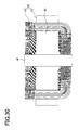
- FIG. 30 is a second view showing the inserting step of inserting the rotor in the stator.
- FIG. 31 is a view showing a positional relationship between the double base unit and a stator core.
- FIG. 1 is a perspective view of an outer circumference base unit (“outer base unit”) 11 including five flat conductor wires (i.e., five wire portions) simultaneously formed.
- FIG. 2 is a front view of the outer base unit 11 of FIG. 1 .
- FIG. 3 is a plan view of the same seen from above in FIG. 2 .
- FIG. 4 is a right side view of FIG. 2 .
- the outer base unit 11 includes an in-slot conductor portion SA and an in-slot conductor portion SB to be placed respectively in slots.
- the in-slot conductor portion SA consists of five flat conductor wires overlapping each other so that their long-side surfaces (flatwise surfaces) are in face-to-face contact with each other.
- the in-slot conductor portion SA indicates an assembly of a first in-slot conductor portion SA 1 , a second in-slot conductor portion SA 2 , a third in-slot conductor portion SA 3 , a fourth in-slot conductor portion SA 4 , and a fifth in-slot conductor portion SA 5 .
- the in-slot conductor portion SB consists of five flat conductor wires overlapping with their long-side surfaces (flatwise surfaces) being in face-to-face contact with each other.
- the in-slot conductor portion SB indicates an assembly of a first in-slot conductor portion SB 1 , a second in-slot conductor portion SB 2 , a third in-slot conductor portion SB 3 , a fourth in-slot conductor portion SB 4 , and a fifth in-slot conductor portion SB 5 .
- the raised portion G includes a lane change portion GA and a lane change portion GB as shown in FIG. 3 .
- the lane change portion GA consists of an assembly of four flat conductor wires.
- One flat conductor wire lacks because a slant portion EA 5 mentioned later is continuous to a terminal M protruding outside.
- the lane change portion GB consists of an assembly of four flat conductor wires.
- One flat conductor wire lacks because a slant portion EB 1 mentioned later is continuous to a terminal N protruding outside.
- the raised portion G is an assembly of four flat conductor wires.
- a bent portion IA is formed at an upper end of the in-slot conductor portion SA.
- the flat conductor wires are bent at the bent portion IA toward the raised portion G as shown in FIG. 2 .
- a slant portion EA is formed between the raised portion G and the in-slot conductor portion SA.
- the bent portion IA indicates an assembly of bent portions IA 1 , IA 2 , IA 3 , IA 4 , and IA 5 of five flat conductor wires as shown in FIG. 3 .
- the slant portion EA indicates an assembly of slant portions EA 1 , EA 2 , EA 3 , EA 4 , and EA 5 of five flat conductor wires as shown in FIG. 4 .
- a bent portion IB is formed at an upper end of the in-slot conductor portion SB.
- the flat conductor wires are bent at the bent portion D 3 toward the raised portion G as shown in FIG. 2 .
- a slant portion EB is formed between the raised portion G and the in-slot conductor portion SB.
- the bent portion D 3 indicates an assembly of bent portions IB 1 , IB 2 , IB 3 , IB 4 , and IB 5 of five flat conductor wires as shown in FIG. 3 .
- the slant portion EB indicates an assembly of slant portions EB 1 , EB 2 , EB 3 , EB 4 , and EB 5 of five flat conductor wires as shown in FIG. 3 .
- the terminal M of EA 5 located on an outermost peripheral side of the slant portion EA is bent to protrude outside.
- the terminal N of EB 1 located on an innermost peripheral side of the slant portion EB is bent to protrude outside.
- a bent portion JA is formed at a lower end of the in-slot conductor portion SA. As shown in FIG. 4 , the flat conductor wires are bent 90° toward the inner periphery side (leftward in the figure) at the bent portion JA.
- the bent portion JA indicates an assembly of bent portions JA 1 , JA 2 , JA 3 , JA 4 , and JA 5 of five flat conductor wires as shown in FIG. 1 .
- a bent portion JB is formed at a lower end of the in-slot conductor portion SB.
- the flat conductor wires are bent 90° toward the inner periphery side (leftward in the figure) at the bent portion JB.
- the bent portion JB indicates an assembly of bent portions JB 1 , JB 2 , JB 3 , JB 4 , and JB 5 of five flat conductor wires as shown in FIG. 1 .
- a semicircular portion H is formed. As shown in FIG. 2 , a horizontal portion FA is formed between the bent portion JA and the semicircular portion H. A horizontal portion FB is formed between the bent portion JB and the semicircular portion H.
- the semicircular portion H indicates an assembly of semicircular portions H 1 , H 2 , H 3 , H 4 , and H 5 of five flat conductor wires as shown in FIGS. 1 and 2 .
- the semicircular portion H has a semicircular shape when viewed from above as shown in FIG. 3 (a plan view) and is formed as a step joining the horizontal portion FB and the horizontal portion FA when viewed from front as shown in FIG. 2 (a front view).
- the size of this step is designed to be larger than the thickness of the horizontal portion FA (the horizontal portion FB).
- the horizontal portion FA indicates an assembly of horizontal portions FA 1 , FA 2 , FA 3 , FA 4 , and FA 5 of five flat conductor wires as shown in FIG. 2 .
- the horizontal portion FB indicates an assembly of horizontal portions FB 1 , FB 2 , FB 3 , FB 4 , and FB 5 of five flat conductor wires as shown in FIG. 2 .
- five flat conductor wires overlap each other in the axial direction (in the vertical direction in FIG. 2 ) with the flatwise surfaces of the flat conductor wires placed in face-to-face contact with each other.
- FIG. 5 is a perspective view of the inner base unit 12 formed of five flat conductor wires shaped at the same time.
- FIG. 6 is a front view of the inner base unit 12 of FIG. 5 .
- FIG. 7 is a plan view of the same seen from above in FIG. 7 .
- FIG. 8 is a right side view of FIG. 6 .
- the structure of the inner base unit 12 is identical to the outer base unit 11 and simply has the size entirely smaller than the outer base unit 11 because the unit 12 is placed inside the outer base unit 11 . Identical parts are therefore given the same reference signs and their details are not repeated.
- a manufacturing method of the outer base unit 11 is the same as that of the unit 11 .
- the manufacturing method of the base units 11 and 12 includes a winding step, an outer periphery forming step, a circular-arc forming step, a lane change portion forming step, and a bending step.
- FIG. 9 is a plan view of a coil 21 wound in the winding step of the manufacturing process of the base units 11 and 12 .
- the flat conductor wire used herein has a cross-section of about 1 mm ⁇ about 10 mm.
- the flat conductor wire is made of copper and formed with a nichrome-plated layer on an outer periphery.
- the coil 21 has terminals M and N at both ends.
- the flat conductor wire is wound to overlap in the flatwise direction.
- the flat conductor wire is wound with gradual outward displacement as it is lower.
- the flat conductor wire is wound with a displacement by a length (about 10 mm) in the flatwise direction of the flat conductor wire.
- the outer periphery forming step will be explained below.
- FIGS. 11 and 12 show the outer periphery forming step of the manufacturing process of the base units 11 and 12 .
- FIG. 12 is a right side view of FIG. 11 .
- a first intermediate coil 21 formed of a flat conductor wire wound by five turns in the winding step is set in an outer periphery forming position in a die 30 as shown in FIG. 11 .
- a jig 34 is arranged in a position facing the slant portion EA.
- a jig 37 is placed in a position facing the raised portion G.
- a jig 33 is disposed in a position facing the slant portion EB.
- a jig 32 is arranged in a position facing the in-slot conductor portion SA.
- a jig 31 is placed in a position facing the in-slot conductor portion SB.
- a jig 35 is disposed in a position facing the horizontal portion FB and a jig 36 is placed in a position facing the semicircular portion H and the horizontal portion FA.
- the jigs 31 , 32 , 33 , 34 , 35 , 36 , and 37 are moved to respective positions shown in FIGS. 11 and 12 to form a second intermediate coil 22 shown in FIG. 10 .
- the semicircular portion H and the horizontal portion FA are configured so that the flat conductor wires are displaced by a length (about 10 mm) in the flatwise direction as shown in FIG. 10 .
- the circular-arc forming step will be explained below.
- the coil 22 is held between a lower die 38 and a pair of upper dies 39 to gently bend the coil 22 into a circular-arc shape, thereby forming a third intermediate coil 23 shown in FIG. 13 .
- the lane change portion forming step will be explained.
- This is a process to form the lane change portion GA and the lane change portion GB in the raised portion G of the third intermediate coil 23 shown in FIG. 13 .
- the coil 23 is held between a lower die 141 , a lower die 144 , a stepped upper die 142 , and an upper die 143 to simultaneously form the lane change portion GA and the lane change portion GB.
- a part of the coil 23 held between the lower die 144 and the upper die 143 is moved in an up and down direction relative to a part of the coil 23 held between the lower die 141 and the upper die 142 , thereby forming the lane change portions GA and GB.
- FIG. 15 shows a coil 24 formed with the lane change portions GA and GB.
- the coil 24 is clamped by a movable die 51 .
- the movable die 51 is held to be movable relative to a fixed die 52 .
- the movable die 51 is moved with respect to the fixed die 52 to form the bent portions JA and JB as shown in FIG. 18 .
- the flat conductor wires are displaced by a length in a flatwise direction.
- the angle between the in-slot conductor portion SA and the horizontal portion FA is different by wires (turns).
- the semicircular portion H and the horizontal portion FA are respectively formed of the flat conductor wires overlapping one another at the same radial position as shown in FIGS. 1 to 4 .
- FIG. 19 is a perspective view of the double base unit 13 .
- FIG. 20 is a front view of the double base unit 13
- FIG. 21 is a plan view of FIG. 20
- FIG. 22 is a right side view of FIG. 20 .
- the inner base unit 12 is located inside of the outer base unit 11 .
- a raised portion 12 G, a slant portion 12 EA, and a slant portion 12 EB of the inner base unit 12 are positioned respectively inside (closer to the stator core) of a raised portion 11 G, a slant portion 11 EA, and a slant portion 11 EB of the outer base unit 11 in an axial direction.
- in-slot conductor portions 12 SA and 12 SB of the inner base unit 12 are located respectively on the inner circumferential side of in-slot conductor portions 11 SA and 11 SB of the outer base unit 11 .
- a semicircular portion 12 H, a horizontal portion 12 FA, a horizontal portion 12 FB of the inner base unit 12 are located respectively on an outside (inside with reference to the stator core), in the radial direction, of a semicircular portion 11 H, a horizontal portion 11 FA, and a horizontal portion 11 FB of the outer base unit 11 .
- FIG. 23 shows an assembly 16 in which double base units 13 U, 13 V, and 13 W of three phases, that is, U phase, V phase, and W phase, are combined.
- the assembly 16 is illustrated in a perspective view in which a U-phase first outer base unit 11 (U 1 ), a U-phase first inner base unit 12 (U 1 ), a V-phase first outer base unit 11 (V 1 ), a V-phase first inner base unit 12 (V 1 ), a W-phase first outer base unit 11 (W 1 ), and a W-phase first inner base unit 12 (W 1 ) are overlapped.
- the slant portion 12 (U 1 )EB of the U-phase first inner base unit 12 (U 1 ) is overlapped under the slant portion 11 (U 1 )EB of the U-phase first outer base unit 11 (U 1 ) in the axial direction (in a direction toward the stator core 15 ).
- the slant portion 11 (V 1 )EB of the V-phase first outer base unit 11 (V 1 ) is overlapped under the slant portion 12 (U 1 )EB of the U-phase first inner base unit 12 (U 1 ) in the axial direction.
- the slant portion 11 (U 1 )EA of the U-phase first outer base unit 11 (U 1 ) is overlapped on the upper side (in an opposite direction to the stator core 15 ) of the slant portion 12 (U 1 )EA of the U-phase first inner base unit 12 (U 1 ) in the axial direction.
- the slant portion 11 (V 1 )EA of the V-phase first outer base unit 11 (V 1 ) is overlapped on the upper side of the slant portion 12 (U 1 )EA of the U-phase first inner base unit 12 (U 1 ) in the axial direction.
- the horizontal portion 12 (U 1 )FB of the U-phase first inner base unit 12 (U 1 ) overlaps, in a radial, clockwise outward position (on the inner side relative to the stator core), on the horizontal portion 11 (U 1 )FB of the U-phase first outer base unit 11 (U 1 ).
- the horizontal portion 11 (V 1 )FB of the V-phase first outer base unit 11 (V 1 ) overlaps, in a radial, clockwise outward position, on the horizontal portion 12 (U 1 )FB of the U-phase first inner base unit 12 (U 1 ).
- the horizontal portion 12 (U 1 ) FA of the U-phase first inner base unit 12 (U 1 ) overlaps, in a radial, clockwise inward position, on the horizontal portion 11 (U 1 ) of the U-phase first outer base unit 11 (U 1 ).
- the horizontal portion 11 (V 1 ) of the V-phase first outer base unit 11 (V 1 ) overlaps, in a radial, clockwise inward position, on the horizontal portion 12 (U 1 )FA of the U-phase first inner base unit 12 (U 1 ).
- a raised portion 11 (U 1 )G of the U-phase first outer base unit 11 (U 1 ), a raised portion 11 (V 1 )G of the V-phase first outer base unit 11 (V 1 ), and a raised portion 11 (W 1 )G of the W-phase first outer base unit 11 (W) are displaced in the radial direction.
- a semicircular portion 11 (U 1 )H of the U-phase first outer base unit 11 (U 1 ), a semicircular portion 11 (V 1 )H of the V-phase first outer base unit 11 (V 1 ), and a semicircular portion 11 (W 1 )H of the W-phase first outer base unit 11 (W 1 ) are displaced in the radial direction.
- this assembly takes a semicircular form.
- Two of such assemblies are manufactured and combined to complete a circular cage-shaped coil (case coil) 14 including twenty-four outer base units 11 and the twenty-four inner base units 12 in overlapping fashion.
- the configuration of the cage coil 14 is shown in a perspective view of FIG. 24 .
- the stator core of a stator of a motor in the present embodiment has forty-eight slots and forty-eight teeth.
- Each of the outer base unit 11 and the inner base unit 12 includes two in-slot conductor portions SA and SB. These in-slot conductor portions SA and SB are located with a lane change corresponding to the thickness of five flat conductor wires in the radial direction as shown in FIG. 27 .
- the stator core 15 is formed with forty-eight slots S as shown in FIGS. 24 and 27 .
- the slots S include a total of eight group blocks; a first group block B 1 , a second group block B 2 , . . . , an eighth group block B 8 .
- Each group block B includes six slots; a U-phase first slot SU 1 , a U-phase second slot SU 2 , a V-phase first slot SV 1 , a V-phase second slot SV 2 , a W-phase first slot SW 1 , and a W-phase second slot SW 2 .
- the U-phase first slot SU 1 , the U-phase second slot SU 2 , the V-phase first slot SV 1 , the V-phase second slot SV 2 , the W-phase first slot SW 1 , and the W-phase second slot SW 2 are referred collectively to as a slot S.
- the in-slot conductor portion 11 (U 1 )SB of the U-phase first outer base unit 11 (U 1 ) is inserted.
- the in-slot conductor portion 12 (U 1 )SB of the U-phase first inner base unit 12 (U 1 ) is inserted.
- the in-slot conductor portion 11 (V 1 )SB of the V-phase first outer base unit 11 (V 1 ) is inserted on the inner periphery side of the V-phase first slot SV 1 of the first group block B 1 .
- the in-slot conductor portion 12 (V 1 )SB of the V-phase first inner base unit 12 (V 1 ) is inserted on the inner periphery side of the V-phase second slot SV 2 .
- the in-slot conductor portion 11 (W 1 )SB of the W-phase first outer base unit 11 (W 1 ) is inserted.
- the in-slot conductor portion 12 (W 1 ) of the W-phase first inner base unit 12 (W 1 ) is inserted.
- the in-slot conductor portion 12 (U 1 )SA of the U-phase first inner base unit 12 (U 1 ) is inserted.
- the in-slot conductor portion 11 (U 1 )SA of the U-phase first outer base unit 11 (U 1 ) is inserted.
- the in-slot conductor portion 12 (V 1 )SA of the V-phase first inner base unit 12 (V 1 ) is inserted.
- the in-slot conductor portion 11 (V 1 )SA of the V-phase first outer base unit 11 (V 1 ) is inserted.
- the in-slot conductor portion 12 (W 1 )SA of the W-phase first inner base unit 12 (W 1 ) is inserted.
- the in-slot conductor portion 11 (W 1 )SA of the W-phase first outer base unit 11 (W 1 ) is inserted.
- the in-slot conductor portions SA and SB are inserted in turn in the corresponding slots of the third group block B 3 , the fourth group block B 4 , the fifth group block B 5 , the sixth group block B 6 , and the seventh group block B 7 .
- the in-slot conductor portion 11 (U 8 )SB of the U-phase eighth outer base unit 11 (U 8 ) is inserted.
- the in-slot conductor portion 12 (U 8 )SB of the U-phase eighth inner base unit 12 (U 8 ) is inserted.
- the in-slot conductor portion 11 (V 8 )SB of the V-phase eighth outer base unit 11 (V 8 ) is inserted on the inner periphery side of the V-phase first slot SV 1 of the eighth block B 8 .
- the in-slot conductor portion 12 (V 8 )SB of the V-phase eighth inner base unit 12 (V 8 ) is inserted on the inner periphery side of the V-phase second slot SV 2 .
- the in-slot conductor portion 11 (W 8 )SB of the W-phase eighth outer base unit 11 (W 8 ) is inserted on the inner periphery side of the W-phase first slot SW 1 of the eighth block B 8 .
- the in-slot conductor portion 12 (W 8 )SB of the W-phase eighth inner base unit 12 (W 8 ) is inserted on the inner periphery side of the W-phase second slot SW 2 .
- the in-slot conductor portion 12 (U 8 )SA of the U-phase eighth inner base unit 12 (U 8 ) is inserted.
- the in-slot conductor portion 11 (U 8 )SA of the U-phase eighth outer base unit 11 (U 8 ) is inserted.
- the in-slot conductor portion 12 (V 8 )SA of the V-phase eighth inner base unit 12 (V 8 ) is inserted.
- the in-slot conductor portion 11 (V 8 )SA of the V-phase eighth outer base unit 11 (V 8 ) is inserted.
- the in-slot conductor portion 12 (W 8 )SA of the W-phase eighth inner base unit 12 (W 8 ) is inserted.
- the in-slot conductor portion 11 (W 8 )SA of the W-phase eighth outer base unit 11 (W 8 ) is inserted.
- Three phases i.e., U phase, V phase, and W phase, each include sixteen base units having eight outer base units 11 and eight inner base units 12 , that is, a total of forty-eight base units.
- each slot two sets of flat conductor wires, each set having five flat conductor wires, i.e., a total of ten flat conductor wires, are inserted.
- FIGS. 24 and 25 show that a lower part of the cage coil 14 is inserted by about half into the stator core 15 . Since it may be difficult to understand if the entire cage coil 14 is illustrated, FIG. 25 shows only the assembly 16 (the same shown in FIG. 23 ) consisting of the double base units 13 U, 13 V, and 13 W for three U, V, and W phases, which is a part of the cage coil 14 . Although the following explanation is given to an inserting operation of the assembly 16 which is a part of the cage coil 14 is explained, the same inserting operation also applies to the entire cage coil 14 . Even though the insulator is not illustrated, it is preferable to mount the insulator in each slot S of the stator core 15 before the cage coil 14 is inserted.
- the semicircular portions 11 (U 1 )H, 12 (U 1 )H, 11 (V 1 )H, 12 (V 1 )H, 11 (W 1 )H, 12 (W 1 )H, the horizontal portions 11 (U 1 )FB, 12 (U 1 )FB, 11 (V 1 )FB, 12 (V 1 )FB, 11 (W 1 )FB, and 12 (W 1 )FB, and the horizontal portions 11 (U 1 )FA, 12 (U 1 )FA, 11 (V 1 )FA, 12 (V 1 )FA, 11 (W 1 )FA, and 12 (W 1 )FA of the U-phase first outer base unit 11 (U 1 ), the U-phase first inner base unit 12 (U 1 ), the V-phase first outer base unit 11 (V 1 ), the V-phase first inner base unit 12 (V 1 ), the W-phase first outer base unit 11 (W 1 ), and the W-phase first inner base unit 12 (W 1 ) are located further toward
- the cage coil 14 can be inserted in the slots S of the stator core 15 .
- in-slot conductor portions 11 (U 1 )SB (SB 1 to SB 5 ) of the U-phase first outer base unit 11 (U 1 ) are inserted on the inner periphery side of the U-phase first slot SU 1 of the first group block B 1 .
- the other-side in-slot conductor portions 11 (U 1 )SA (SA 1 to SA 5 ) are inserted on the outer periphery side of the U-phase second slot SU 2 of the second group block B 2 .
- FIG. 26 shows a state where the cage coil 14 is inserted to a predetermined position with respect to the stator core 15 .
- FIG. 27 is a plan view of the stator core 15 of FIG. 26 , seen from above in the axis.
- FIG. 28 is a front view of FIG. 26 .
- the reason why the positions of the semicircular portions H, the horizontal portions F 13 , and the horizontal portions FA are spaced from the end face of the stator core 15 is to prevent the cage coil 14 from affecting the rotor.
- FIG. 29 is a cross-sectional view of the stator 10 taken along a central axis, in which the cage coil 14 is assembled with the stator core 15 .
- the cage coil 14 is not exist in a further inward position than the inner peripheral surfaces 15 b of the teeth 15 a .
- the semicircular portions H the horizontal portions FA, and the horizontal portions FB, which are the bent portions of the cage coil 14 are located in a further inward position than the inner peripheral surfaces 15 b of the teeth 15 a.
- the motor rotor 42 is formed with a rotor part 43 around a center shaft 41 .
- the rotor 42 can be inserted into the stator 10 axially from above, but cannot be inserted into the stator 10 from below.
- FIG. 30 shows a state where the rotor 42 is inserted in the stator 10 .
- the center shaft 41 of the rotor 42 protrudes from a center hole defined by inner peripheral surfaces of the semicircular portions H of the cage coil 14 .
- the lane change portions G of the outer base units 11 and the inner base units 12 each occupy an angle corresponding to two slots.
- a “two-slot region” described herein represents the width of two slots and two teeth assuming that one slot and one tooth are defined as a one-slot region.
- the present embodiment adopts a double coil, so that this lane change portion can use a double, two-slot region.
- This is suitable for a flat conductor wire which preferably has as wide a width as possible in relation to the bending radius. That is, increasing the cross sectional area of a flat conductor wire is effective in enhancing the space factor. As the cross sectional area is larger, the bending radius is also relatively larger. According to the present embodiment, therefore, a stator with high space factor can be provided.
- the stator 10 includes the cage coil 14 formed of the flat conductor wire in a distributed winding arrangement and the stator core 15 formed with the slots between the teeth, and the rotor 42 having the central axis.
- group blocks B each including the U-phase first slot SU 1 , U-phase second slot SU 2 , V-phase first slot SV 1 , V-phase second slot SV 2 , W-phase first slot SW 1 , and W-phase second slot SW 2 are sequentially formed so that the second group block B 2 is located adjacent to the first group block B 1 .
- the flat conductor wires in the U-phase first slot SU 1 of the first group block B 1 and the flat conductor wires in the U-phase second slot SU 2 of the second group block B 2 form the outer base unit 11 (a first loop).
- the flat conductor wires in the U-phase second slot SU 2 of the first group block B 1 and the flat conductor wires in the U-phase first slot SU 1 of the second group block B 1 form the inner base unit 12 (a second loop).
- the inner base unit 12 is located inside of the outer base unit 11 .
- the coil end portion at one end of the inner base unit 12 and the coil end portion A at one end of the outer base unit 11 are bent toward the rotor 42 side with respect to the in-slot conductor portions SA and SB of the stator core 15 .
- the coil end portion A side at one end of the inner base unit 12 and the coil end portion A side at one end of the outer base unit 11 are located further toward the axis of the rotor 42 than the inner peripheral surface of the stator core 15 .
- the cage coil 14 when the cage coil 14 is to be inserted with its coil end portion A at one end directing as a leading end into the slots of the stator core 15 , the coil end portion A side at one end passes through the more inner side than the inner peripheral surface of the stator core 15 and therefore the coil can be easily inserted in the slots along the axial direction. Since the coil is not elastically deformed when it is inserted, a part of the coil is less likely to protrude out of the slots due to spring back.
- the flat conductor wire is shaped into the double coil including the outer base unit 11 and the inner base unit 12 , spaces for the lane change portions G can be ensured.
- the wires are arranged in planar form on the end face of the stator core 15 .
- the end face of the stator core 15 has a restricted area, it is difficult to increase the number of wires to increase the number of turns of the coil.
- the concentrically wound coils interfere with each other, and therefore the lane change portions G are needed in the coil end portion. In the lane change portions G, the coil width is apt to become an issue.
- the end face of the stator core can be utilized in three dimensions.
- the number of turns of a coil can be increased. Even in the case where the number of turns in increased, it is also possible to prevent interference between adjacent coils with each other in the lane change portions G.
- the double coil is formed by combining the outer base unit 11 and the inner base unit 12 in an overlapping configuration.
- the stator core 15 with deep slots can be adopted without so increasing the thickness of the coil end. Consequently, the demands for enhancement of the space factor of the stator and for reduction of size thereof can be satisfied.
- the lane change portions G are necessary when a coil is concentrically wound and a stator is arranged in a distributed winding form. This is because if the concentrically wound coils are inserted by straddling or skipping two or more slots, an interference portion occurs between the adjacent coils and thus it is necessary to avoid such an interference portion.
- the present embodiment adopts the double coil (the outer base unit 11 and the inner base unit 12 ) and therefore each lane change portion G can use a two-slot range as shown in FIG. 27 .
- the flat conductor wire is designed to have as wide a width as possible because of the bending radius.
- the present embodiment can provide the stator with high space factor.
- outer base unit 11 and the inner base unit 12 are each formed as a base unit formed by bending a predetermined number of flat conductor wires at the same time. Accordingly, the wires wound in overlapping form (a base unit) are bent at the same time as being held in such an overlapping wound form. This can simplify the manufacturing process and reduce its cost.
- the flat conductor wires of each of the outer base unit 11 and the inner base unit 12 overlap in the axis direction of the rotor 42 .
- the flat conductor wires of each of the outer base unit 11 and the inner base unit 12 overlap in the radial direction of the rotor 42 . Accordingly, on the coil end portion B at the other end in which the flat conductor wires overlap one another in the radial direction, the coil end can have a reduced size in the axial direction. Simultaneously, on the coil end portion A at one end in which the flat conductor wires overlap one another in the axial direction, the bent coil end can have a reduced size in the radial direction.
- the coil end portion A side at one end of the inner base unit 12 overlaps, outward in a radial direction of the rotor 42 , on the coil end portion A side at one end of the outer base unit 11 .
- the coil end portion B at the other end of the inner base unit 12 overlaps, inside in the axial direction of the rotor 42 , with the coil end portion B side of the outer base unit 11 . Accordingly, on the coil end portion B side at the other end, the units 11 and 12 overlap in the axial direction, thereby reducing the size in the radial direction. Simultaneously, on the coil end portion A side at one end, the units 11 and 12 overlap in the radial direction, thereby reducing the size in the axial direction.
- the flat conductor wires of each of the outer base unit 11 and the inner base unit 12 overlap in the radial direction and also the base units overlap in the axial direction.
- the flat conductor wires can be collected up three-dimensionally.
- the volume of the coil end at the other end can be reduced.
- the flat conductor wires of each of the outer base unit 11 and the inner base unit 12 overlap in the axial direction and also the base units overlap in the radial direction. This can collect up the flat conductor wires three-dimensionally. Thus, the volume of the coil end at the one end can be reduced.
- the radius of the curved portion (the bent portions JA and JB) which is a connecting portion with one-side in-slot conductor portion is different by wires (turns) before the wires are bent. After the wires of each base unit are bent simultaneously, the wires on the coil end portion A side at one end can overlap at the same radial position.
- portions of the outer base unit 11 and the inner base unit 12 each forming the coil end at one end are displaced.
- the wires of each of the outer base unit 11 and the inner base unit 12 overlap one another at the same radial position.
- the wires of each of the outer base unit 11 and the inner base unit 12 can be bent at the same time to overlap one another on the coil end portion A side at one end and coincide in the radial direction.
- the present invention is used in for example a motor of a hybrid electric vehicle.
Landscapes
- Engineering & Computer Science (AREA)
- Power Engineering (AREA)
- Manufacturing & Machinery (AREA)
- Windings For Motors And Generators (AREA)
- Manufacture Of Motors, Generators (AREA)
Applications Claiming Priority (3)
| Application Number | Priority Date | Filing Date | Title |
|---|---|---|---|
| JP2010133067A JP5292360B2 (ja) | 2010-06-10 | 2010-06-10 | モータ |
| JP2010-133067 | 2010-06-10 | ||
| PCT/JP2010/065215 WO2011155083A1 (ja) | 2010-06-10 | 2010-09-06 | モータ |
Publications (2)
| Publication Number | Publication Date |
|---|---|
| US20120181891A1 US20120181891A1 (en) | 2012-07-19 |
| US8884489B2 true US8884489B2 (en) | 2014-11-11 |
Family
ID=45097710
Family Applications (1)
| Application Number | Title | Priority Date | Filing Date |
|---|---|---|---|
| US13/499,665 Expired - Fee Related US8884489B2 (en) | 2010-06-10 | 2010-09-06 | Motor |
Country Status (6)
| Country | Link |
|---|---|
| US (1) | US8884489B2 (de) |
| EP (1) | EP2582017A4 (de) |
| JP (1) | JP5292360B2 (de) |
| KR (1) | KR101279336B1 (de) |
| CN (1) | CN102474144B (de) |
| WO (1) | WO2011155083A1 (de) |
Cited By (4)
| Publication number | Priority date | Publication date | Assignee | Title |
|---|---|---|---|---|
| US9570966B2 (en) | 2012-02-28 | 2017-02-14 | Aisin Aw Co., Ltd. | Method for manufacturing a coil |
| US9859775B2 (en) * | 2013-03-29 | 2018-01-02 | Aisin Aw Co., Ltd. | Method for forming a concentric winding coil |
| US10250092B2 (en) * | 2013-08-26 | 2019-04-02 | Mitsubishi Electric Corporation | Rotary electric machine |
| US10432049B2 (en) | 2014-04-10 | 2019-10-01 | Moteurs Leroy-Somer | Rotor for a rotary electric machine |
Families Citing this family (33)
| Publication number | Priority date | Publication date | Assignee | Title |
|---|---|---|---|---|
| JP5385166B2 (ja) * | 2010-01-22 | 2014-01-08 | 日立オートモティブシステムズ株式会社 | 回転電機 |
| JP5363403B2 (ja) * | 2010-04-19 | 2013-12-11 | トヨタ自動車株式会社 | モータ |
| JP5278555B2 (ja) * | 2011-03-08 | 2013-09-04 | トヨタ自動車株式会社 | モータ製造方法 |
| JP5278553B2 (ja) * | 2011-03-08 | 2013-09-04 | トヨタ自動車株式会社 | モータ製造方法 |
| JP5674693B2 (ja) * | 2012-03-01 | 2015-02-25 | アイシン・エィ・ダブリュ株式会社 | 巻線成形装置および巻線成形方法 |
| JP5785117B2 (ja) * | 2012-03-02 | 2015-09-24 | アイシン・エィ・ダブリュ株式会社 | 巻線装置および巻線方法 |
| WO2013179477A1 (ja) * | 2012-06-01 | 2013-12-05 | 株式会社安川電機 | 回転電機、回転電機用ステータおよび車両 |
| JP5885176B2 (ja) * | 2012-09-26 | 2016-03-15 | 三菱電機株式会社 | 電気機械用電機子巻線の製造方法 |
| JP5232941B1 (ja) * | 2012-09-28 | 2013-07-10 | 株式会社林工業所 | 誘導モータ用のバスバー |
| JP5474166B1 (ja) * | 2012-11-15 | 2014-04-16 | 三菱電機株式会社 | 固定子 |
| JP5920258B2 (ja) * | 2013-03-19 | 2016-05-18 | 株式会社安川電機 | コイル製造用巻線部材、コイル、回転電機およびコイルの製造方法 |
| JP6140566B2 (ja) * | 2013-07-31 | 2017-05-31 | アイシン・エィ・ダブリュ株式会社 | コイル装着方法及びコイル装着治具 |
| JP5681250B1 (ja) * | 2013-08-27 | 2015-03-04 | 本田技研工業株式会社 | 導線片セット成形方法及び導線片セット成形装置 |
| JP6206052B2 (ja) * | 2013-09-30 | 2017-10-04 | アイシン・エィ・ダブリュ株式会社 | 同芯巻コイルの成形方法及び成形装置 |
| JP6206051B2 (ja) * | 2013-09-30 | 2017-10-04 | アイシン・エィ・ダブリュ株式会社 | 同芯巻コイルの成形方法及び成形装置 |
| JP6257470B2 (ja) * | 2014-08-06 | 2018-01-10 | 三菱電機株式会社 | 回転電機の固定子コイルおよび回転電機の固定子コイルの製造方法 |
| US11018564B2 (en) * | 2015-09-30 | 2021-05-25 | Aisin Aw Co., Ltd. | Method for forming coil and apparatus for forming coil |
| DE102015225798A1 (de) * | 2015-12-09 | 2017-06-14 | Robert Bosch Gmbh | Stator für eine elektrische Maschine |
| JP6107990B2 (ja) * | 2016-03-02 | 2017-04-05 | 株式会社安川電機 | コイル製造用巻線部材 |
| CN106300716B (zh) * | 2016-06-17 | 2018-08-03 | 浙江方正电机股份有限公司 | 三相电机定子 |
| US11843334B2 (en) | 2017-07-13 | 2023-12-12 | Denso Corporation | Rotating electrical machine |
| CN113991958A (zh) | 2017-07-21 | 2022-01-28 | 株式会社电装 | 旋转电机 |
| JP6430599B1 (ja) | 2017-08-04 | 2018-11-28 | 株式会社小田原エンジニアリング | コイルセグメント成形装置、コイルセグメント成形方法及び回転電機の製造装置 |
| JP6939750B2 (ja) | 2017-12-28 | 2021-09-22 | 株式会社デンソー | 回転電機 |
| DE112018006699T5 (de) | 2017-12-28 | 2020-09-10 | Denso Corporation | Rotierende elektrische Maschine |
| DE112018006694T5 (de) | 2017-12-28 | 2020-09-10 | Denso Corporation | Rotierende elektrische Maschine |
| CN111566904B (zh) | 2017-12-28 | 2023-04-28 | 株式会社电装 | 旋转电机 |
| JP7006541B2 (ja) | 2017-12-28 | 2022-01-24 | 株式会社デンソー | 回転電機 |
| JP6922868B2 (ja) | 2017-12-28 | 2021-08-18 | 株式会社デンソー | 回転電機システム |
| CN113647000A (zh) * | 2019-03-27 | 2021-11-12 | 日本电产株式会社 | 定子的制造方法以及定子 |
| JP7346892B2 (ja) * | 2019-04-19 | 2023-09-20 | 株式会社デンソー | 回転電機 |
| DE102019220415A1 (de) * | 2019-12-20 | 2021-06-24 | Fraunhofer-Gesellschaft zur Förderung der angewandten Forschung eingetragener Verein | Vorrichtung und Verfahren zum Biegen von elektrisch leitenden Profilen für Elektromotoren (Hairpin) |
| WO2021176668A1 (ja) | 2020-03-05 | 2021-09-10 | 株式会社デンソー | 回転電機 |
Citations (10)
| Publication number | Priority date | Publication date | Assignee | Title |
|---|---|---|---|---|
| WO1992001327A1 (de) | 1990-07-07 | 1992-01-23 | Zahnradfabrik Friedrichshafen Ag | Verfahren zur herstellung einer statorwicklung mit profilleitern für elektrische maschinen |
| JPH04289744A (ja) | 1991-03-18 | 1992-10-14 | Toshiba Corp | 三相6極電機子巻線 |
| JP2002051489A (ja) | 2000-08-02 | 2002-02-15 | Aisin Aw Co Ltd | 回転電機及びその製造方法 |
| US20070170810A1 (en) * | 2003-11-03 | 2007-07-26 | Light Engineering, Inc. | Stator coil arrangement for an axial airgap electric device including low-loss materials |
| JP2008167567A (ja) | 2006-12-28 | 2008-07-17 | Hitachi Ltd | 回転電機 |
| WO2010007950A1 (ja) | 2008-07-14 | 2010-01-21 | アイシン・エィ・ダブリュ株式会社 | ステータ及びその製造方法 |
| US20100102681A1 (en) * | 2008-10-23 | 2010-04-29 | Aisin Aw Co., Ltd. | Rotating electrical machine |
| US20100187938A1 (en) * | 2009-01-28 | 2010-07-29 | Aisin Aw Co., Ltd. | Armature for rotating electrical machine and manufacturing method thereof |
| WO2011055438A1 (ja) | 2009-11-05 | 2011-05-12 | トヨタ自動車株式会社 | ステータ及びステータ製造方法 |
| US20120217836A1 (en) * | 2010-10-14 | 2012-08-30 | Toyota Jidosha Kabushiki Kaisha | Motor |
Family Cites Families (5)
| Publication number | Priority date | Publication date | Assignee | Title |
|---|---|---|---|---|
| JP3928297B2 (ja) * | 1999-03-26 | 2007-06-13 | 日産自動車株式会社 | 電動機及びその製造方法 |
| JP2001320845A (ja) | 2000-05-10 | 2001-11-16 | Mitsubishi Electric Corp | 回転電機の固定子 |
| JP3798968B2 (ja) * | 2001-11-08 | 2006-07-19 | 三菱電機株式会社 | 回転電機の固定子の製造方法 |
| JP3786059B2 (ja) * | 2002-06-25 | 2006-06-14 | 株式会社デンソー | 回転電機のセグメント順次接合ステータコイルおよびその製造方法 |
| JP4546112B2 (ja) * | 2004-03-02 | 2010-09-15 | 日立オートモティブシステムズ株式会社 | 回転電機 |
-
2010
- 2010-06-10 JP JP2010133067A patent/JP5292360B2/ja not_active Expired - Fee Related
- 2010-09-06 WO PCT/JP2010/065215 patent/WO2011155083A1/ja not_active Ceased
- 2010-09-06 KR KR1020127001704A patent/KR101279336B1/ko not_active Expired - Fee Related
- 2010-09-06 CN CN201080036683.6A patent/CN102474144B/zh not_active Expired - Fee Related
- 2010-09-06 US US13/499,665 patent/US8884489B2/en not_active Expired - Fee Related
- 2010-09-06 EP EP10852918.1A patent/EP2582017A4/de not_active Withdrawn
Patent Citations (11)
| Publication number | Priority date | Publication date | Assignee | Title |
|---|---|---|---|---|
| WO1992001327A1 (de) | 1990-07-07 | 1992-01-23 | Zahnradfabrik Friedrichshafen Ag | Verfahren zur herstellung einer statorwicklung mit profilleitern für elektrische maschinen |
| JPH04289744A (ja) | 1991-03-18 | 1992-10-14 | Toshiba Corp | 三相6極電機子巻線 |
| JP2002051489A (ja) | 2000-08-02 | 2002-02-15 | Aisin Aw Co Ltd | 回転電機及びその製造方法 |
| US20070170810A1 (en) * | 2003-11-03 | 2007-07-26 | Light Engineering, Inc. | Stator coil arrangement for an axial airgap electric device including low-loss materials |
| JP2008167567A (ja) | 2006-12-28 | 2008-07-17 | Hitachi Ltd | 回転電機 |
| WO2010007950A1 (ja) | 2008-07-14 | 2010-01-21 | アイシン・エィ・ダブリュ株式会社 | ステータ及びその製造方法 |
| US20100289374A1 (en) * | 2008-07-14 | 2010-11-18 | Aisin Aw Co., Ltd | Stator and manufacturing method thereof |
| US20100102681A1 (en) * | 2008-10-23 | 2010-04-29 | Aisin Aw Co., Ltd. | Rotating electrical machine |
| US20100187938A1 (en) * | 2009-01-28 | 2010-07-29 | Aisin Aw Co., Ltd. | Armature for rotating electrical machine and manufacturing method thereof |
| WO2011055438A1 (ja) | 2009-11-05 | 2011-05-12 | トヨタ自動車株式会社 | ステータ及びステータ製造方法 |
| US20120217836A1 (en) * | 2010-10-14 | 2012-08-30 | Toyota Jidosha Kabushiki Kaisha | Motor |
Non-Patent Citations (1)
| Title |
|---|
| International Search Report of PCT/JP2010/065215 mailed Dec. 14, 2010. |
Cited By (4)
| Publication number | Priority date | Publication date | Assignee | Title |
|---|---|---|---|---|
| US9570966B2 (en) | 2012-02-28 | 2017-02-14 | Aisin Aw Co., Ltd. | Method for manufacturing a coil |
| US9859775B2 (en) * | 2013-03-29 | 2018-01-02 | Aisin Aw Co., Ltd. | Method for forming a concentric winding coil |
| US10250092B2 (en) * | 2013-08-26 | 2019-04-02 | Mitsubishi Electric Corporation | Rotary electric machine |
| US10432049B2 (en) | 2014-04-10 | 2019-10-01 | Moteurs Leroy-Somer | Rotor for a rotary electric machine |
Also Published As
| Publication number | Publication date |
|---|---|
| EP2582017A4 (de) | 2016-12-14 |
| CN102474144A (zh) | 2012-05-23 |
| JP2011259636A (ja) | 2011-12-22 |
| KR20120042853A (ko) | 2012-05-03 |
| EP2582017A1 (de) | 2013-04-17 |
| CN102474144B (zh) | 2014-04-23 |
| US20120181891A1 (en) | 2012-07-19 |
| JP5292360B2 (ja) | 2013-09-18 |
| WO2011155083A1 (ja) | 2011-12-15 |
| KR101279336B1 (ko) | 2013-06-26 |
Similar Documents
| Publication | Publication Date | Title |
|---|---|---|
| US8884489B2 (en) | Motor | |
| US9214847B2 (en) | Motor, and motor production method | |
| US8427024B2 (en) | Stator | |
| JP5560176B2 (ja) | モータ及びモータ製造方法 | |
| US8587177B2 (en) | Stator and method of manufacturing unit coil to be used therein | |
| US8674577B2 (en) | Stator for electric rotating machine | |
| US8779643B2 (en) | Stator for electric rotating machine and method of manufacturing same | |
| US8450899B2 (en) | Stator for electric rotating machine | |
| US8250734B2 (en) | Insertion of pre-fabricated concentrated windings into stator slots | |
| US9712010B2 (en) | Motor having a cage wave stator winding | |
| EP2782224B1 (de) | Spulenherstellungsverfahren | |
| US20140021823A1 (en) | Stator and manufacturing method for stator | |
| CN103548242B (zh) | 用于制造尤其是交流电机的电机的定子绕组的方法 | |
| JP5370491B2 (ja) | ステータ及びステータ製造方法 | |
| JP5382469B2 (ja) | 回転電機用固定子巻線の製造方法 | |
| US8397368B2 (en) | Method of manufacturing stator for electric rotating machine | |
| US20140030078A1 (en) | Stator and method of manufacturing stator | |
| CN104604104A (zh) | 旋转电机 | |
| US8581467B2 (en) | Stator including a cage coil | |
| US8826713B2 (en) | Method and apparatus for manufacturing stator coil for electric rotating machine | |
| JP2018088729A (ja) | 回転電機のステータ | |
| CN106411014A (zh) | 旋转电机及其制造方法、定子线圈、线圈树脂结构体 | |
| US20090313810A1 (en) | Method of manufacturing coil assembly of stator of electric rotating machine | |
| CN108781006B (zh) | 旋转电机、旋转电机的制造方法 | |
| JP5483111B2 (ja) | 回転電機用固定子巻線の製造方法 |
Legal Events
| Date | Code | Title | Description |
|---|---|---|---|
| AS | Assignment |
Owner name: AISIN AW CO., LTD., JAPAN Free format text: ASSIGNMENT OF ASSIGNORS INTEREST;ASSIGNORS:YAMADA, TAKASHI;WATANABE, ATSUSHI;KITAMURA, MANABU;AND OTHERS;REEL/FRAME:027967/0733 Effective date: 20120215 Owner name: TOYOTA JIDOSHA KABUSHIKI KAISHA, JAPAN Free format text: ASSIGNMENT OF ASSIGNORS INTEREST;ASSIGNORS:YAMADA, TAKASHI;WATANABE, ATSUSHI;KITAMURA, MANABU;AND OTHERS;REEL/FRAME:027967/0733 Effective date: 20120215 |
|
| STCF | Information on status: patent grant |
Free format text: PATENTED CASE |
|
| MAFP | Maintenance fee payment |
Free format text: PAYMENT OF MAINTENANCE FEE, 4TH YEAR, LARGE ENTITY (ORIGINAL EVENT CODE: M1551) Year of fee payment: 4 |
|
| FEPP | Fee payment procedure |
Free format text: MAINTENANCE FEE REMINDER MAILED (ORIGINAL EVENT CODE: REM.); ENTITY STATUS OF PATENT OWNER: LARGE ENTITY |
|
| LAPS | Lapse for failure to pay maintenance fees |
Free format text: PATENT EXPIRED FOR FAILURE TO PAY MAINTENANCE FEES (ORIGINAL EVENT CODE: EXP.); ENTITY STATUS OF PATENT OWNER: LARGE ENTITY |
|
| STCH | Information on status: patent discontinuation |
Free format text: PATENT EXPIRED DUE TO NONPAYMENT OF MAINTENANCE FEES UNDER 37 CFR 1.362 |
|
| FP | Lapsed due to failure to pay maintenance fee |
Effective date: 20221111 |