US8925232B2 - Pistol with firing mechanism that can easily be adapted to various modes of operation - Google Patents
Pistol with firing mechanism that can easily be adapted to various modes of operation Download PDFInfo
- Publication number
- US8925232B2 US8925232B2 US13/582,256 US201013582256A US8925232B2 US 8925232 B2 US8925232 B2 US 8925232B2 US 201013582256 A US201013582256 A US 201013582256A US 8925232 B2 US8925232 B2 US 8925232B2
- Authority
- US
- United States
- Prior art keywords
- rod
- pistol
- arm
- crosswise
- firing device
- Prior art date
- Legal status (The legal status is an assumption and is not a legal conclusion. Google has not performed a legal analysis and makes no representation as to the accuracy of the status listed.)
- Active, expires
Links
- 238000010304 firing Methods 0.000 title claims description 101
- 239000002184 metal Substances 0.000 claims description 5
- 238000011144 upstream manufacturing Methods 0.000 claims description 2
- 230000009471 action Effects 0.000 description 35
- 238000006073 displacement reaction Methods 0.000 description 9
- 238000004519 manufacturing process Methods 0.000 description 6
- 238000000034 method Methods 0.000 description 4
- 230000036961 partial effect Effects 0.000 description 4
- 238000009527 percussion Methods 0.000 description 4
- 230000000284 resting effect Effects 0.000 description 4
- 230000000903 blocking effect Effects 0.000 description 3
- 230000000694 effects Effects 0.000 description 3
- 230000003993 interaction Effects 0.000 description 3
- 230000003213 activating effect Effects 0.000 description 2
- 230000001351 cycling effect Effects 0.000 description 2
- 230000002452 interceptive effect Effects 0.000 description 2
- 230000004913 activation Effects 0.000 description 1
- 230000008859 change Effects 0.000 description 1
- 238000010276 construction Methods 0.000 description 1
- 238000003780 insertion Methods 0.000 description 1
- 230000037431 insertion Effects 0.000 description 1
- 230000000670 limiting effect Effects 0.000 description 1
- 238000012986 modification Methods 0.000 description 1
- 230000004048 modification Effects 0.000 description 1
- 238000005457 optimization Methods 0.000 description 1
- 230000008569 process Effects 0.000 description 1
- 230000002829 reductive effect Effects 0.000 description 1
- 238000006467 substitution reaction Methods 0.000 description 1
Images




Classifications
-
- F—MECHANICAL ENGINEERING; LIGHTING; HEATING; WEAPONS; BLASTING
- F41—WEAPONS
- F41A—FUNCTIONAL FEATURES OR DETAILS COMMON TO BOTH SMALLARMS AND ORDNANCE, e.g. CANNONS; MOUNTINGS FOR SMALLARMS OR ORDNANCE
- F41A19/00—Firing or trigger mechanisms; Cocking mechanisms
- F41A19/06—Mechanical firing mechanisms, e.g. counterrecoil firing, recoil actuated firing mechanisms
- F41A19/13—Percussion or firing pins, i.e. fixed or slidably-mounted striker elements; Mountings therefor
-
- F—MECHANICAL ENGINEERING; LIGHTING; HEATING; WEAPONS; BLASTING
- F41—WEAPONS
- F41A—FUNCTIONAL FEATURES OR DETAILS COMMON TO BOTH SMALLARMS AND ORDNANCE, e.g. CANNONS; MOUNTINGS FOR SMALLARMS OR ORDNANCE
- F41A19/00—Firing or trigger mechanisms; Cocking mechanisms
- F41A19/06—Mechanical firing mechanisms, e.g. counterrecoil firing, recoil actuated firing mechanisms
- F41A19/16—Adjustable firing mechanisms; Trigger mechanisms with adjustable trigger pull
-
- F—MECHANICAL ENGINEERING; LIGHTING; HEATING; WEAPONS; BLASTING
- F41—WEAPONS
- F41A—FUNCTIONAL FEATURES OR DETAILS COMMON TO BOTH SMALLARMS AND ORDNANCE, e.g. CANNONS; MOUNTINGS FOR SMALLARMS OR ORDNANCE
- F41A19/00—Firing or trigger mechanisms; Cocking mechanisms
- F41A19/06—Mechanical firing mechanisms, e.g. counterrecoil firing, recoil actuated firing mechanisms
- F41A19/12—Sears; Sear mountings
-
- F—MECHANICAL ENGINEERING; LIGHTING; HEATING; WEAPONS; BLASTING
- F41—WEAPONS
- F41A—FUNCTIONAL FEATURES OR DETAILS COMMON TO BOTH SMALLARMS AND ORDNANCE, e.g. CANNONS; MOUNTINGS FOR SMALLARMS OR ORDNANCE
- F41A19/00—Firing or trigger mechanisms; Cocking mechanisms
- F41A19/06—Mechanical firing mechanisms, e.g. counterrecoil firing, recoil actuated firing mechanisms
- F41A19/15—Modular firing mechanism units
-
- F—MECHANICAL ENGINEERING; LIGHTING; HEATING; WEAPONS; BLASTING
- F41—WEAPONS
- F41A—FUNCTIONAL FEATURES OR DETAILS COMMON TO BOTH SMALLARMS AND ORDNANCE, e.g. CANNONS; MOUNTINGS FOR SMALLARMS OR ORDNANCE
- F41A19/00—Firing or trigger mechanisms; Cocking mechanisms
- F41A19/06—Mechanical firing mechanisms, e.g. counterrecoil firing, recoil actuated firing mechanisms
- F41A19/25—Mechanical firing mechanisms, e.g. counterrecoil firing, recoil actuated firing mechanisms having only slidably-mounted striker elements, i.e. percussion or firing pins
- F41A19/27—Mechanical firing mechanisms, e.g. counterrecoil firing, recoil actuated firing mechanisms having only slidably-mounted striker elements, i.e. percussion or firing pins the percussion or firing pin being movable relative to the breech-block
- F41A19/29—Mechanical firing mechanisms, e.g. counterrecoil firing, recoil actuated firing mechanisms having only slidably-mounted striker elements, i.e. percussion or firing pins the percussion or firing pin being movable relative to the breech-block propelled by a spring under tension
- F41A19/30—Mechanical firing mechanisms, e.g. counterrecoil firing, recoil actuated firing mechanisms having only slidably-mounted striker elements, i.e. percussion or firing pins the percussion or firing pin being movable relative to the breech-block propelled by a spring under tension in bolt-action guns
- F41A19/31—Sear arrangements therefor
-
- F—MECHANICAL ENGINEERING; LIGHTING; HEATING; WEAPONS; BLASTING
- F41—WEAPONS
- F41A—FUNCTIONAL FEATURES OR DETAILS COMMON TO BOTH SMALLARMS AND ORDNANCE, e.g. CANNONS; MOUNTINGS FOR SMALLARMS OR ORDNANCE
- F41A19/00—Firing or trigger mechanisms; Cocking mechanisms
- F41A19/06—Mechanical firing mechanisms, e.g. counterrecoil firing, recoil actuated firing mechanisms
- F41A19/25—Mechanical firing mechanisms, e.g. counterrecoil firing, recoil actuated firing mechanisms having only slidably-mounted striker elements, i.e. percussion or firing pins
- F41A19/27—Mechanical firing mechanisms, e.g. counterrecoil firing, recoil actuated firing mechanisms having only slidably-mounted striker elements, i.e. percussion or firing pins the percussion or firing pin being movable relative to the breech-block
- F41A19/29—Mechanical firing mechanisms, e.g. counterrecoil firing, recoil actuated firing mechanisms having only slidably-mounted striker elements, i.e. percussion or firing pins the percussion or firing pin being movable relative to the breech-block propelled by a spring under tension
- F41A19/30—Mechanical firing mechanisms, e.g. counterrecoil firing, recoil actuated firing mechanisms having only slidably-mounted striker elements, i.e. percussion or firing pins the percussion or firing pin being movable relative to the breech-block propelled by a spring under tension in bolt-action guns
- F41A19/34—Cocking mechanisms
-
- F—MECHANICAL ENGINEERING; LIGHTING; HEATING; WEAPONS; BLASTING
- F41—WEAPONS
- F41A—FUNCTIONAL FEATURES OR DETAILS COMMON TO BOTH SMALLARMS AND ORDNANCE, e.g. CANNONS; MOUNTINGS FOR SMALLARMS OR ORDNANCE
- F41A19/00—Firing or trigger mechanisms; Cocking mechanisms
- F41A19/06—Mechanical firing mechanisms, e.g. counterrecoil firing, recoil actuated firing mechanisms
- F41A19/25—Mechanical firing mechanisms, e.g. counterrecoil firing, recoil actuated firing mechanisms having only slidably-mounted striker elements, i.e. percussion or firing pins
- F41A19/27—Mechanical firing mechanisms, e.g. counterrecoil firing, recoil actuated firing mechanisms having only slidably-mounted striker elements, i.e. percussion or firing pins the percussion or firing pin being movable relative to the breech-block
- F41A19/29—Mechanical firing mechanisms, e.g. counterrecoil firing, recoil actuated firing mechanisms having only slidably-mounted striker elements, i.e. percussion or firing pins the percussion or firing pin being movable relative to the breech-block propelled by a spring under tension
- F41A19/30—Mechanical firing mechanisms, e.g. counterrecoil firing, recoil actuated firing mechanisms having only slidably-mounted striker elements, i.e. percussion or firing pins the percussion or firing pin being movable relative to the breech-block propelled by a spring under tension in bolt-action guns
- F41A19/34—Cocking mechanisms
- F41A19/35—Double-action mechanisms, i.e. the cocking being effected during the first part of the trigger pull movement
-
- F—MECHANICAL ENGINEERING; LIGHTING; HEATING; WEAPONS; BLASTING
- F41—WEAPONS
- F41A—FUNCTIONAL FEATURES OR DETAILS COMMON TO BOTH SMALLARMS AND ORDNANCE, e.g. CANNONS; MOUNTINGS FOR SMALLARMS OR ORDNANCE
- F41A19/00—Firing or trigger mechanisms; Cocking mechanisms
- F41A19/06—Mechanical firing mechanisms, e.g. counterrecoil firing, recoil actuated firing mechanisms
- F41A19/42—Mechanical firing mechanisms, e.g. counterrecoil firing, recoil actuated firing mechanisms having at least one hammer
- F41A19/43—Mechanical firing mechanisms, e.g. counterrecoil firing, recoil actuated firing mechanisms having at least one hammer in bolt-action guns
- F41A19/47—Cocking mechanisms
-
- F—MECHANICAL ENGINEERING; LIGHTING; HEATING; WEAPONS; BLASTING
- F41—WEAPONS
- F41A—FUNCTIONAL FEATURES OR DETAILS COMMON TO BOTH SMALLARMS AND ORDNANCE, e.g. CANNONS; MOUNTINGS FOR SMALLARMS OR ORDNANCE
- F41A19/00—Firing or trigger mechanisms; Cocking mechanisms
- F41A19/06—Mechanical firing mechanisms, e.g. counterrecoil firing, recoil actuated firing mechanisms
- F41A19/42—Mechanical firing mechanisms, e.g. counterrecoil firing, recoil actuated firing mechanisms having at least one hammer
- F41A19/43—Mechanical firing mechanisms, e.g. counterrecoil firing, recoil actuated firing mechanisms having at least one hammer in bolt-action guns
- F41A19/47—Cocking mechanisms
- F41A19/48—Double-action mechanisms, i.e. the cocking being effected during the first part of the trigger pull movement
Definitions
- the present invention refers to a pistol, more specifically a pistol comprising a firing device presenting a basic configuration which is easily adaptable for in different modes.
- a firing device for a pistol which, with a few modifications, may be converted so to operate in double action, single action and alternating double action/single action modes.
- another object of the present invention is to provide a family or a series of pistols comprising double action pistols, single action pistols and alternate (double or single) action pistols, produced from a basic project, so as to reduce the costs of the project, production and assembly of their components and body, thus allowing an optimization of the project and therefore of the final pistols, whichever is their mode of operation.
- a basic pistol intended to activate in the DAO mode, a pistol with a firing device which is easily adaptable to various modes of operation, comprising a frame which moves about a bolt, said frame comprising a handle, within which is housed the magazine, the trigger guard involving the trigger and a metal back support intended to house part of the components of the pistol firing device, wherein said firing device comprises said trigger, pivotably hinged to a first end of the rod, wherein the opposite end of said rod is located on the back support, and said bolt involves and houses the firing pin spring, located on the back portion and aligned with the chamber where the cartridge is located, and said bolt having, around its front portion, the spring of the firing pin, which acts over the backstop and, on its back portion, a finger projecting downwards.
- Said pistol also comprises a rod, in the shape of a laminar element forming and including, in said edge opposed to the trigger, a tip and a crosswise arm, wherein said crosswise arm is projected from the lengthwise body of the rod, towards the central portion of the pistol, and includes a front surface, able to mechanically interfere with said tongue, and a flap, facing the crosswise arm and projecting downwards, in the middle region of which an oblong hole is included; a rod guiding, fixed in relation to the back support, with its longitudinal axle parallel to the length of the piston, wherein said rod pin crosses the oblong hole of the flap of the crosswise arm, so as to limit the movement upwards and downwards of said crosswise arm; and a rod ramp, in the shape of an elongated laminar body, fixed by a lower end to a crosswise axle and having in the opposite and upper end a fold projecting away from the center of the pistol to define a contact surface that mechanically acts against the rod tip.
- a pistol directed to act in the SA mode which firing device also includes: a bushing, in the form of a cylinder with a central hole and located around the rod guiding pin and upstream of the flap of the crosswise arm of the rod, so as to limit the forward movement of said rod; and a rod ramp also comprising a disconnecting arm, which is vertically projected upwards and includes, in its upper end, a projection able to mechanically interfere with a rib, located on the inner side of the fixing flap where said bolt slides in, so as to displace said rod ramp inwardly in relation to the pistol.
- a second alternative pistol intended to work in the DA/SA mode, also comprising: a rod ramp also comprising a disconnecting arm, which is vertically projected upwards and includes, on its upper end, a projection able to mechanically interfere with a rib, located on the inner side of the fixing flap where said bolt slides in, so as to displace said rod ramp inwardly in relation to the pistol; a rod lock in the form of a hinge over a respective axle located parallel to the crosswise axle of the pistol, defining: a lower portion of said rod lock, having an outer surface able to be activated by a key, as well as a spring, located in the inside of said lower portion, so as to constantly push said lower portion outside, and an upper portion of the rod bolt, comprising an arm which extends parallel to the rod bolt axle, as well as a head located on the upper end of said rod bolt; and a stopper, basically in the form of a cube, provided with a central hole through which said stopper is assembled over the rod guiding pin
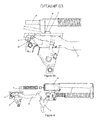
- FIG. 1 is an upper side view of a pistol of the present invention, in partial section and showing its main components;
- FIGS. 2 to 10 are schematic views showing a pistol with DAO mode of operation, in partial section and corresponding to the various steps of operation of this embodiment of the invention
- FIGS. 11 to 20 are schematic views showing a firing device for a pistol of the present invention, only operated in the single action mode, with the switched device in relation to the basic firing device shown by FIGS. 2 to 10 ;
- FIGS. 21 to 28 are schematic views showing a firing device for a pistol of the present invention, operated in the double action/single action mode.
- a firing device for a pistol with only double action which device may be easily adapted to obtain a single action (SA) pistol and also a double/single action (DA/SA) pistol.
- SA single action
- DA/SA double/single action
- FIG. 1 is a schematic upper side view of a pistol 1 only of the double action (DAO) type, having a frame 10 , including the handle 2 , located on the lower back portion thereof, the lower portion of the bolt 6 and the guides (not shown) to slide said bolt 6 over the frame 10 .
- the frame 10 is an injected polymeric structure provided with a few metal insertions, wherein said guides slide the bolt 6 , as well as the back support 3 , located above the handle 2 and intended to house part of the components of the firing device of the pistol 1 , which will be disclosed in detail further below.
- the trigger guard 28 is also formed as a single part from the frame 10 .
- a housing is included to receive the magazine 4 intended to store and supply the cartridges 11 as known in the art.
- the trigger 5 is included, which is hinged or pivoted to said frame 10 of the pistol 1 or, more specifically, said trigger 5 is hinged to the central support of the frame 10 , which is a metal part housed inside the frame 10 .
- the upper portion of the pistol comprises the bolt 6 which can slide back and forth over said frame 10 , by means of said four guides (not shown), said bolt 6 in its frontal portion involves the barrel 7 and the respective return spring 8 .
- the chamber 9 is included in order to house a cartridge 11 , which chamber is located, with the pistol 1 in a resting position, in a lengthwise position equal to the trigger 5 .
- the back portion of the bolt 6 covers the firing pin 12 and the respective spring of the firing pin spring 13 .
- FIGS. 2 to 10 showing schematic views of the firing device for the pistol 1 operated only in the double action (DAO) mode, show components of the firing device, with parts removed not to compromise the clarity of the figures.
- DAO double action
- the trigger 5 hinged to said central support of the frame 10 , is hinged mounted to the rod 14 , so that the movements made by the trigger 5 are transferred to the rod 14 and vice versa.
- Said rod 14 has the shape of a conformed laminar element and includes, on its end opposite to the trigger 5 , a tip 16 and a crosswise arm 17 . More specifically, the crosswise arm 17 is projected from the longitudinal body of the rod 14 towards the central portion of the pistol 1 , and has a front surface 18 , able to mechanically interact with a finger 24 projected from the firing pin 12 and a flap 19 facing the crosswise arm 17 and projected downwards, in the central portion where an oblong hole 20 is provided, where the rod guiding pin 21 is included.
- the rod guiding pin 21 is fixed to said metal back support of the frame 10 and is intended to limit the upward and downward movement of the rod 14 , but not to limit its back and forth movement.
- Said tip 16 of the rod 14 acts against the rod ramp 30 which, on a lower end, is fixed to a crosswise axle 22 and, on the opposite and upper end, has a fold projecting away from the center of the pistol 1 , thus defining a contact surface with the tip 16 of the rod 14 .
- the firing pin 12 is located inside the region as limited by the bolt 6 and is able to move freely, back and forth, in relation to said bolt 6 . More particularly, the firing pin 12 has a cylindrical shape, provided with a tip 23 in its front portion for the percussion of the cartridge 11 , and having in its rear portion a finger 24 , which forms a ramp 27 on its lower back portion, intended to mechanically interact with the crosswise arm 17 of the rod 14 . Furthermore, around the central portion of the firing pin 12 , said firing pin spring 13 is located.
- the pistol 1 is loaded, i.e. it has a cartridge 11 in the respective chamber 9 with the magazine 4 loaded, as well as a trigger in starting course, i.e. in its most advanced position. Therefore, the user starts the firing procedure by moving the trigger 5 backwards, causing the movement of the rod 14 in the same direction.
- Such movement of the rod 14 is guided by the rod guiding pin 21 , so as to guarantee that said rod 14 is not displaced upwards. Consequently, and due to the mechanical interference between the front surface 18 of the crosswise arm 17 of the rod 14 with the finger 24 of the firing pin 12 , said firing pin 12 will also be moved backwards against the resistance as imposed by the firing pin spring 13 , as shown by FIG. 2 .
- FIG. 3 is an enlarged view of the back support 3 of the pistol 1 , from which we can notice that, in that point of the movement, the tip 16 of the rod 14 comes into contact with the rod ramp 30 , thus forcing said rod 14 downwards and therefore lowering the crosswise arm 17 until the release of the finger 24 of the firing pin 12 .
- DET 3 is an enlarged view of the back support 3 of the pistol 1 , from which we can notice that, in that point of the movement, the tip 16 of the rod 14 comes into contact with the rod ramp 30 , thus forcing said rod 14 downwards and therefore lowering the crosswise arm 17 until the release of the finger 24 of the firing pin 12 .
- FIGS. 4 and 5 show the moment of the percussion of the cartridge 11 , where we can see the rod 14 in its lowest position and the finger 24 of the firing pin in an advanced position in relation the crosswise arm 17 of the rod 14 .
- cycling starts, i.e. the procedure to eliminate the fired cartridge, reload the chamber with a new cartridge and reposition the firing device for new firing. Said sequence of events is shown, step by step, on FIGS. 6 to 10 .
- the firing pin 12 follows backwards together with the bolt 6 (please see FIG. 6 —maximum backwards position of the bolt).
- the bolt ends the quick clicking process, supplying the chamber 9 and returning to the front, the user starts to release the trigger 5 , causing the rod 14 of the trigger to follow said forward movement (please see FIG. 7 ).
- the rod 14 backwards its crosswise arm 17 hits the ramp 27 of the finger 24 , thus forcing said rod 14 downwards (please FIGS. 8 and 9 ).
- This movement downwards is limited by the rod guide pin 21 , until the crosswise arm 17 is facing the finger 24 , going up and again locking the bolt 6 , i.e.
- the device taking a similar position to the initial position as shown by FIGS. 10 and 2 . Therefore, the device is fully in its initial position and, at that moment, the user may fire a new shot.
- the trigger 5 returns to its initially more advanced position which, to fire a new shot, should be pulled all the back by the user, repeating the above disclosed steps.
- a second embodiment of the present invention comprises a pistol 40 , such as shown by FIGS. 11 to 20 , relative to the various steps of the firing procedure in SA mode and wherein numerical references similar to those used for FIGS. 2 to 10 show equal components.
- This embodiment basically shows two differences over the previously disclosed one, i.e. the presence of the bushing 42 and a disconnecting arm 43 projecting from the rod ramp 30 ′.
- 42 shows a bushing which is located around the guide pin 21 of the rod 14 working so as to limit the range of displacement of the flap 19 of the crosswise arm 17 of the rod 14 , thus preventing said rod 14 from advancing beyond a given point.
- FIGS. 14 and 15 are schematic upper rear views wherein the rib 45 of the bolt 6 , located in the inner side of the fixing flap 46 wherein said bolt 6 slides can be identified.
- FIG. 11 is a perspective view of the back portion of the pistol 40 , in an equivalent moment as shown by FIG. 3 above, i.e. with the trigger 5 being pulled backward by the action of the user of the pistol 40 .
- the rod 14 moves backwards and is lowered by the action of the tip 16 under the ramp 30 ′ (please refer to FIG. 12 for a similar view to FIG. 11 with the rod 14 almost fully lowered).
- the crosswise arm 17 is also lowered until the physical contact between the front surface 18 of the crosswise arm 17 and the finger 24 of the firing pin 12 is lost. At that moment, the firing pin 12 is released and hits the cartridge 11 (please refer to FIG.
- FIGS. 14 and 15 are schematic upper end views showing two consecutive moments during the backwards movement of the bolt 6 , respectively with the rod 14 in an intermediate position ( FIG. 14 ) and later in a fully upper position ( FIG. 15 ).
- the tip 16 loses contact with the rod ramp 30 ′ and is pushed upwards (we remind that, at this point, the trigger 5 is still pulled backwards by the user, thus forcing the rod 14 backwards).
- FIGS. 16 to 19 are upper side views showing the return of the bolt 6 from its maximum backwards position to its resting or initial position. Therefore, due to the upper position of the rod 14 , the finger 24 of the firing pin 12 hits the front surface 18 of the crosswise arm 17 , and therefore cannot move forward. Said blocking effected on the rod 14 is also the result of the presence of the bushing 42 which, as stated, prevents the crosswise arm 17 of the rod 14 from moving forward (please see FIG. 17 ).
- FIG. 7 shows the return of the bolt 6 and the firing pin 12 , which is possible due to the lowered position of the rod 14 and particularly its crosswise arm 17 , allowing the finger 24 of the firing pin 12 to pass over a crosswise arm 17 with no mechanical interference between them.
- FIGS. 18 and 19 show intermediate return positions for the trigger 5 to its operational position in SA, with the corresponding return of the rod 14
- FIG. 20 shows the pistol 40 in its final position.
- the firing pin 12 gradually returns to its position just as the trigger 5 is released by the user.
- the finger 24 of the firing pin 12 remains in contact with the crosswise arm 17 during the whole displacement of the rod 14 , remaining in this position until a new shot is fired.
- the trigger 5 and the rod 14 remain in an intermediate position between the initial position of the pistol 40 ( FIG. 11 ) and the firing position of the gun. Said effect is due to the presence of the bushing 42 limiting the return path of the rod 14 and therefore the trigger 5 .
- the user will need to move the trigger 5 through a shorter path to release the firing pin 12 and fire the cartridge 11 , i.e. eliminating the whole initial step of movement backwards of the rod to engage the finger 24 of the firing pin 12 , just like in the DA operation mode.
- the differences existing between the SA embodiment ( FIGS. 11 to 20 ) and the DAO embodiment are limited to the inclusion of the bushing 42 and the disconnecting arm 43 .
- the bolt rib 45 is also present in the DAO embodiment, but said bolt rib 45 does not act on the rod ramp 30 due to the non-existence of said disconnecting arm 43 and the respective projection 44 . Said solution allows to reach the objects of maximum standardization of the production line, whichever is the model of pistol to be produced, i.e. reducing at maximum the differences and particularities between them.
- the simple and efficient inclusion of the bushing 42 and the disconnecting arm 43 allows changing both the course of displacement and the position of the crosswise arm 17 , and therefore the whole rod 14 . Therefore, and after the return of the bolt 6 , the firing pin can no longer advance freely, since it is blocked by the crosswise arm 17 , now located in a backward upper position, thus interfering with the return path of the finger 24 of the firing pin 12 .
- FIGS. 21 to 28 wherein numeric references similar to those used for FIGS. 1 to 20 show equivalent components.
- the firing device of this embodiment of the pistol allows its use in both DA and SA modes, depending on the circumstances.
- the bushing 42 must be included in the rod guiding pin 21 , to avoid the free movement forward of the rod 14 when the bolt 6 returning, and also by the inclusion disconnecting arm 43 , relative to the rod ramp 30 ′ and mechanically activated by the bolt 6 .
- the pistol 50 In the present DA/SA mode of actuation, the pistol 50 must be able to work in the DA mode and in the SA mode. More specifically, said DA/SA actuation form is defined by a first shot in DA mode and by consecutive shots in SA mode, until the user returns the pistol 50 to the DA mode of firing, by voluntarily activating the external key or in the case of an involuntary firing failure.
- the inventor has devised a firing device wherein a mobile element is included, to work like the bushing 42 in the SA mode pistol 40 , but which can also be displaced from its blocking position, thus allowing the pistol 50 to also work in DA mode.
- the enhancements of the present embodiment are both the disconnecting arm 43 of the rod ramp 30 ′, with its respective upper projection 44 (just like shown and disclosed in the embodiment of the SA mode pistol 40 ), as well as a rod lock 51 and a respective stopper 52 for the rod lock 51 .
- FIG. 21 is an upper view in partial section of the back portion of the pistol 50 , according to an embodiment of the present invention, in its resting position, while FIGS. 22 to 28 correspond to the various steps to activate the pistol 50 , after starting to activate the trigger 5 .
- FIG. 21 initially highlights the presence of the disconnecting arm 43 , which has, on its upper end, an upper projection 44 , i.e. exactly the same as the disconnecting arm 43 as shown by FIGS. 11 to 20 for the pistol 40 .
- the form of activation of the disconnecting arm 43 is exactly the same as the corresponding disconnecting arm 43 of the pistol 40 , including with reference to its interaction with the bolt rib 45 present on the flap 46 of the bolt 6 .
- the pistol 50 of the DA/SA mode also comprises the rod lock 51 and a respective stopper 52 (please refer specifically to FIG. 23 ).
- the rod lock 51 has the shape of a hinge to a respective axle 53 located parallel to the crosswise axle of the pistol 50 .
- the lower portion 54 or arm of said rod lock 51 has an external surface able to be activated by a key (not shown) fixed to the rear side of the pistol 50 , said key may be activated by the user as we will see in the description of the operation of the pistol 50 further below.
- the upper portion 56 of the rod lock 51 comprises an arm 57 which extends parallel to the axle 53 of the rod lock 51 , as well as a head 58 located at the upper end of said rod lock 51 .
- the stopper 52 is also included, presenting basically the shape of a cube, provided with a central hole (please refer to FIG. 25 ) through which said stopper 52 is assembled over the rod guiding pin 21 . Furthermore, and around the rod guiding pin 21 , the spring 59 is located, to push said stopper 52 forward. The stopper 52 is unable to spin around said rod guiding pin 21 , since its housing in the back support 3 does not allow its angular movement. On the other hand, said stopper 52 may be displaced lengthwise, and its maximum advance position is limited by the flap 19 of the crosswise arm 17 of the rod 14 .
- the stopper 52 may assume two possible positions.
- the first one is the maximum advanced position of the stopper 52 , in which the arm 57 of the rod lock 51 is supported by the side of the rod lock 51 , being therefore forced out against the action of the spring 55 , being said position of the rod lock 51 called “open” herein.
- the second position just like better shown by FIGS. 24 and 25 , i.e. the maximum backward position of the stopper 52 , is the position in which the stopper 52 loses contact with the arm 57 of the rod lock 51 and is kept in recess against the action of the spring 59 located around the rod guiding pin 21 .
- the spring 55 acts on the lower portion 54 of the rod lock 51 , causing the head 58 to be displaced to inside the pistol 50 and, more specifically, interfering with the displacement of the flap 19 of the crosswise arm 17 of the rod 14 , wherein said position of the rod lock 51 is herein called “closed”.
- the head 58 of the rod lock 51 takes the same position of the bushing 42 of the firing device of the pistol 40 , i.e. it interferes with the advance movement of said rod 14 .
- FIG. 22 is a schematic view in perspective with the trigger 5 in an intermediate position, i.e. between the initial and the final firing position.
- the tip 16 abuts the rod ramp 30 ′ during its return movement and is forced downwards due to that interaction with the rod ramp 30 ′.
- FIGS. 23 and 24 are schematic perspective views in partial section showing the left side of the pistol 50 , i.e. the side where the rod lock 51 is positioned, in two consecutive moments.
- FIG. 25 is an upper end view with the pistol 50 in the same situation as shown by FIG. 24 , i.e. shortly before firing. From those figures, we can see that, by retracting the rod 14 , the stopper 52 is pushed back by the retraction movement of the flap 19 of the crosswise arm 17 of the rod 14 , causing the arm 57 of the rod lock 51 to no longer abut the side surface of the stopper 52 , and thus the rod lock 51 switches from the open position ( FIG. 23 ) to a closed position ( FIGS. 24 and 25 ).
- the finger 24 of the firing pin 12 loses contact with the front surface 18 of the crosswise arm 17 , and is then quickly advanced by the action of the firing pin Spring 13 , striking and firing the cartridge 11 located inside the chamber 9 (please refer to FIG. 26 ).
- FIG. 27 is a schematic end perspective view.
- the retraction of the bolt 6 causes its bolt rib 45 to act on the upper projection 44 of the disconnecting arm 43 , thus displacing the rod ramp 30 ′ inwards and allowing the elevation of the crosswise arm 17 of the rod 14 .
- the finger 24 of the firing pin 12 also interacts with the head 58 of the rod lock 51 , forcing said rod lock 51 to an open position, opposed to the action of the spring 55 .
- FIG. 28 is a similar view to FIG. 27 , but with the lock in its maximum retraction position.
- said firing pin loses contact and returns to the closed position, again against the action of the spring 55 acting over the internal part of the lower portion 54 of the rod lock 51 .
- this position is exactly the same as already disclosed for FIG. 16 of the pistol 40 , with the rod 14 with no contact with the rod ramp 30 ′ at an upper position; furthermore, as the crosswise arm 17 is found in a closed condition, the head 58 takes the same position of the bushing 42 for the pistol 40 .
- said key acting on the lower portion 54 of the rod lock 51 should be pressed. More specifically, said key is located so that, when activated, it compresses the lower portion 54 , thus opening the rod lock 51 . With said opening, the head 58 no longer blocks the advancement of the flap 19 , and therefore the firing pin 12 and the crosswise arm 17 advance to the initial displacement position. As a consequence, the rod 14 pushes the trigger 5 to its maximum extended position, which corresponds to the initial position of use in DA mode (please refer to FIG. 2 ). Therefore, the pistol 50 returns to the DA mode of action wherein, for a later shot, the trigger should be displaced throughout its path, i.e. since the maximum extended position until the firing position as fully pressed by the user.
- the scope of the invention is fully reached. From a simple and efficient device (the firing device of the pistol 1 acting in DAO mode), it is possible to reach both the pistol 40 device (SA) and the pistol 50 device (DA/SA) from the inclusion of a very limited number of parts. Especially, to enable the construction of the pistol 40 from the basic device of the pistol 1 , the rod ramp 30 ′ as used additionally includes the disconnecting arm 43 and the bushing arrangement 42 .
- the basic device of the pistol 1 is used, also with the substitution of the rod ramp 30 with the rod ramp 30 ′ provided with the disconnecting arm 43 (this component is exactly the same as used in the pistol device 40 ), and also including the rod lock 51 and the stopper 52 .
- the assembly line the conception of a basic device, which can easily form three different kinds of pistols, is something innovative and highly appreciated.
- the standardization of components in the firing device allows quicker production, with better quality and especially more economical, bearing in mind the lower quantity of different parts to be manufactured for the assembly of different guns.
- the assembly line for guns can easily support a peak in demand for a specific model of pistol, since the vast majority of their components are identical for all models liable for production from the basic device of the present invention.
Landscapes
- Engineering & Computer Science (AREA)
- General Engineering & Computer Science (AREA)
- Toys (AREA)
Applications Claiming Priority (1)
| Application Number | Priority Date | Filing Date | Title |
|---|---|---|---|
| PCT/BR2010/000015 WO2011085458A1 (fr) | 2010-01-15 | 2010-01-15 | Pistolet à mécanisme de tir facilement adaptable à divers modes de fonctionnement |
Publications (2)
| Publication Number | Publication Date |
|---|---|
| US20130000171A1 US20130000171A1 (en) | 2013-01-03 |
| US8925232B2 true US8925232B2 (en) | 2015-01-06 |
Family
ID=44303742
Family Applications (1)
| Application Number | Title | Priority Date | Filing Date |
|---|---|---|---|
| US13/582,256 Active 2030-03-30 US8925232B2 (en) | 2010-01-15 | 2010-01-15 | Pistol with firing mechanism that can easily be adapted to various modes of operation |
Country Status (3)
| Country | Link |
|---|---|
| US (1) | US8925232B2 (fr) |
| EP (1) | EP2525185B1 (fr) |
| WO (1) | WO2011085458A1 (fr) |
Cited By (10)
| Publication number | Priority date | Publication date | Assignee | Title |
|---|---|---|---|---|
| USD779620S1 (en) * | 2015-12-28 | 2017-02-21 | George Huang | Enhanced magazine release |
| US9927200B2 (en) * | 2015-05-25 | 2018-03-27 | Grand Power, S.R.O. | Trigger mechanics for auto-loading firearm without trigger motion bar with direct control of firing pin catch through one-arm trigger lever |
| US20190226777A1 (en) * | 2018-01-22 | 2019-07-25 | Springfield, Inc. | Firearm slide with sloped bottom surface |
| US10739095B2 (en) * | 2015-12-01 | 2020-08-11 | Mean L.L.C. | Firearm operating system |
| US11280570B2 (en) | 2019-03-11 | 2022-03-22 | James Matthew Underwood | Firearm operating mechanisms and bolt release |
| US11371789B2 (en) | 2019-08-06 | 2022-06-28 | James Matthew Underwood | Roller delayed firearm operating system |
| EP4098967A1 (fr) | 2021-06-01 | 2022-12-07 | Glock Technology GmbH | Dispositif gâchette pour une arme de poing |
| US11543195B2 (en) | 2020-07-03 | 2023-01-03 | James Matthew Underwood | Roller and bearing delayed firearm operating systems |
| US11846476B2 (en) | 2021-10-07 | 2023-12-19 | James Matthew Underwood | Ejector for firearm |
| US12152849B1 (en) | 2024-04-15 | 2024-11-26 | Polaris Capital Corporation | Firearm trigger |
Families Citing this family (15)
| Publication number | Priority date | Publication date | Assignee | Title |
|---|---|---|---|---|
| WO2023022723A1 (fr) * | 2021-08-19 | 2023-02-23 | Tactical Industry Innovations, Llc | Système de détente |
| ITBS20130170A1 (it) * | 2013-11-18 | 2015-05-19 | Francesco Ghitti | Arma da fuoco azionabile con il pollice |
| ES2606327T3 (es) * | 2013-12-11 | 2017-03-23 | Glock Technology Gmbh | Muelle para el empujador del disparador de una pistola |
| SK288474B6 (sk) * | 2014-09-18 | 2017-08-02 | Grand Power, S.R.O. | Spúšťový mechanizmus samonabíjacej zbrane a samonabíjacia ručne ovládaná zbraň |
| CZ306586B6 (cs) | 2015-11-11 | 2017-03-15 | Česká Zbrojovka A.S. | Spoušťové ústrojí pro automatické a poloautomatické pistole |
| JP6129397B1 (ja) * | 2016-12-16 | 2017-05-17 | 正 常定 | ライフル |
| US10684087B2 (en) * | 2017-10-10 | 2020-06-16 | Sig Sauer, Inc. | Handgun sear with multiple engagement surfaces |
| WO2019172054A1 (fr) * | 2018-03-08 | 2019-09-12 | Jsr株式会社 | Composition de résine sensible au rayonnement, procédé de fabrication associé et procédé de formation de motif de réserve |
| USD1042708S1 (en) | 2019-02-13 | 2024-09-17 | Hs Produkt D.O.O. | Firearm slide |
| EP3901555A1 (fr) * | 2020-04-23 | 2021-10-27 | FN Herstal SA | Securite de percuteur d'un pistolet |
| USD1049292S1 (en) | 2021-04-06 | 2024-10-29 | Springfield, Inc. | Pistol |
| USD1069964S1 (en) | 2021-11-03 | 2025-04-08 | Hs Produkt D.O.O. | Pistol slide |
| USD1088169S1 (en) * | 2022-02-23 | 2025-08-12 | Palmetto State Armory, LLC | Firearm frame |
| USD1057882S1 (en) | 2022-08-29 | 2025-01-14 | Springfield, Inc. | Combined serrations for a firearm slide |
| USD1061781S1 (en) * | 2022-11-30 | 2025-02-11 | Hs Produkt D.O.O. | Pistol |
Citations (21)
| Publication number | Priority date | Publication date | Assignee | Title |
|---|---|---|---|---|
| US3722358A (en) | 1971-01-14 | 1973-03-27 | L Seecamp | Combined single and double action firing mechanisms for pistols and kits for converting single-action pistols |
| US4539889A (en) * | 1981-04-30 | 1985-09-10 | Gaston Glock | Automatic pistol with counteracting spring control mechanism |
| US5160796A (en) | 1991-10-07 | 1992-11-03 | Martin Tuma | Automatic small arm |
| US5386659A (en) * | 1993-12-17 | 1995-02-07 | Smith & Wesson Corp. | Fire control mechanism for semiautomatic pistols |
| US5701698A (en) | 1995-03-01 | 1997-12-30 | Carl Walther Gmbh | Trigger mechanism for firearms |
| US5797206A (en) | 1996-12-26 | 1998-08-25 | Smith & Wesson Corp. | Method for reversibly converting a traditional double action pistol to a single action, target pistol |
| US5806225A (en) * | 1995-07-07 | 1998-09-15 | Fn Manufacturing Inc | Fire control mechanism for an automatic pistol |
| BR9700178A (pt) | 1997-01-31 | 1998-12-01 | Forjas Taurus Sa | Mecanismo de disparo para armas de fogo |
| US6308448B1 (en) * | 1999-04-30 | 2001-10-30 | Smith & Wesson Corporation | Angled interlocked firing mechanism |
| US6354032B1 (en) * | 2000-10-06 | 2002-03-12 | Arthur Viani | Trigger stop |
| US6560909B2 (en) * | 2001-06-22 | 2003-05-13 | Joseph Cominolli | Manual safety for linear striker fired semi-automatic or automatic pistols |
| US20050011098A1 (en) | 2003-05-23 | 2005-01-20 | Fagundes De Campos Algeu Jose | Safety device for shooting mechanism of double-action semi-automatic pistols with striker fired |
| US20050034344A1 (en) * | 2003-08-14 | 2005-02-17 | Arthur Viani | Self cleaning trigger control connector & connector |
| US20060248772A1 (en) * | 2004-12-22 | 2006-11-09 | Smith & Wesson Corp. | Fire control mechanism for a firearm |
| US20060249014A1 (en) * | 2004-12-22 | 2006-11-09 | Smith & Wesson Corp. | Apparatus and method for firearm takedown |
| US7140141B2 (en) * | 2001-02-07 | 2006-11-28 | Smith & Wesson Corp. | Apparatus and method for removing the slide of a semi-automatic pistol |
| US7194833B1 (en) * | 2003-02-10 | 2007-03-27 | Smith & Wesson Corp. | Firing mechanism for semi-automatic pistols |
| US20080263926A1 (en) * | 2004-06-09 | 2008-10-30 | Wilhelm Bubits | Pistol with a Trigger Mechanism |
| US7526889B2 (en) * | 2006-07-11 | 2009-05-05 | S.A.T. Swiss Arms Technology Ag | Trigger mechanism for handguns |
| US20100236121A1 (en) * | 2007-07-25 | 2010-09-23 | Mcgarry James | Striker-fired firearm |
| US20110289811A1 (en) * | 2010-05-28 | 2011-12-01 | Gentilini Claudio | De-cocking mechanism for striker-fired semi-automatic pistols |
Family Cites Families (2)
| Publication number | Priority date | Publication date | Assignee | Title |
|---|---|---|---|---|
| US20060236581A1 (en) * | 2005-04-25 | 2006-10-26 | Arthur Viani | Self-cleaning trigger connector system |
| BG66145B1 (bg) * | 2007-11-23 | 2011-07-29 | ПЕЕВ Владимир | Двойнодействащ ударно - спускателен механизъм с късо зацепване |
-
2010
- 2010-01-15 US US13/582,256 patent/US8925232B2/en active Active
- 2010-01-15 EP EP10842784.0A patent/EP2525185B1/fr not_active Not-in-force
- 2010-01-15 WO PCT/BR2010/000015 patent/WO2011085458A1/fr not_active Ceased
Patent Citations (23)
| Publication number | Priority date | Publication date | Assignee | Title |
|---|---|---|---|---|
| US3722358A (en) | 1971-01-14 | 1973-03-27 | L Seecamp | Combined single and double action firing mechanisms for pistols and kits for converting single-action pistols |
| US4539889A (en) * | 1981-04-30 | 1985-09-10 | Gaston Glock | Automatic pistol with counteracting spring control mechanism |
| US5160796A (en) | 1991-10-07 | 1992-11-03 | Martin Tuma | Automatic small arm |
| US5386659A (en) * | 1993-12-17 | 1995-02-07 | Smith & Wesson Corp. | Fire control mechanism for semiautomatic pistols |
| US5701698A (en) | 1995-03-01 | 1997-12-30 | Carl Walther Gmbh | Trigger mechanism for firearms |
| US5806225A (en) * | 1995-07-07 | 1998-09-15 | Fn Manufacturing Inc | Fire control mechanism for an automatic pistol |
| US5797206A (en) | 1996-12-26 | 1998-08-25 | Smith & Wesson Corp. | Method for reversibly converting a traditional double action pistol to a single action, target pistol |
| BR9700178A (pt) | 1997-01-31 | 1998-12-01 | Forjas Taurus Sa | Mecanismo de disparo para armas de fogo |
| US6308448B1 (en) * | 1999-04-30 | 2001-10-30 | Smith & Wesson Corporation | Angled interlocked firing mechanism |
| US6354032B1 (en) * | 2000-10-06 | 2002-03-12 | Arthur Viani | Trigger stop |
| US7140141B2 (en) * | 2001-02-07 | 2006-11-28 | Smith & Wesson Corp. | Apparatus and method for removing the slide of a semi-automatic pistol |
| US6560909B2 (en) * | 2001-06-22 | 2003-05-13 | Joseph Cominolli | Manual safety for linear striker fired semi-automatic or automatic pistols |
| US7194833B1 (en) * | 2003-02-10 | 2007-03-27 | Smith & Wesson Corp. | Firing mechanism for semi-automatic pistols |
| US20050011098A1 (en) | 2003-05-23 | 2005-01-20 | Fagundes De Campos Algeu Jose | Safety device for shooting mechanism of double-action semi-automatic pistols with striker fired |
| US7690144B2 (en) * | 2003-05-23 | 2010-04-06 | Forjas Taurus, S.A. | Safety device for shooting mechanism of double-action semi-automatic striker fired pistols |
| US20050034344A1 (en) * | 2003-08-14 | 2005-02-17 | Arthur Viani | Self cleaning trigger control connector & connector |
| US20080263926A1 (en) * | 2004-06-09 | 2008-10-30 | Wilhelm Bubits | Pistol with a Trigger Mechanism |
| US7500327B2 (en) * | 2004-06-09 | 2009-03-10 | Caracal International Llc | Pistol with a trigger mechanism |
| US20060248772A1 (en) * | 2004-12-22 | 2006-11-09 | Smith & Wesson Corp. | Fire control mechanism for a firearm |
| US20060249014A1 (en) * | 2004-12-22 | 2006-11-09 | Smith & Wesson Corp. | Apparatus and method for firearm takedown |
| US7526889B2 (en) * | 2006-07-11 | 2009-05-05 | S.A.T. Swiss Arms Technology Ag | Trigger mechanism for handguns |
| US20100236121A1 (en) * | 2007-07-25 | 2010-09-23 | Mcgarry James | Striker-fired firearm |
| US20110289811A1 (en) * | 2010-05-28 | 2011-12-01 | Gentilini Claudio | De-cocking mechanism for striker-fired semi-automatic pistols |
Cited By (23)
| Publication number | Priority date | Publication date | Assignee | Title |
|---|---|---|---|---|
| US9927200B2 (en) * | 2015-05-25 | 2018-03-27 | Grand Power, S.R.O. | Trigger mechanics for auto-loading firearm without trigger motion bar with direct control of firing pin catch through one-arm trigger lever |
| US12241703B2 (en) | 2015-12-01 | 2025-03-04 | James Matthew Underwood | Firearm operating system |
| US10739095B2 (en) * | 2015-12-01 | 2020-08-11 | Mean L.L.C. | Firearm operating system |
| US11421954B2 (en) | 2015-12-01 | 2022-08-23 | James Matthew Underwood | Firearm operating system |
| US11725895B2 (en) | 2015-12-01 | 2023-08-15 | James Matthew Underwood | Firearm operating system |
| USD779620S1 (en) * | 2015-12-28 | 2017-02-21 | George Huang | Enhanced magazine release |
| US20190226777A1 (en) * | 2018-01-22 | 2019-07-25 | Springfield, Inc. | Firearm slide with sloped bottom surface |
| US10760861B2 (en) * | 2018-01-22 | 2020-09-01 | Springfield, Inc. | Firearm slide with sloped bottom surface |
| US11280570B2 (en) | 2019-03-11 | 2022-03-22 | James Matthew Underwood | Firearm operating mechanisms and bolt release |
| US12305943B2 (en) | 2019-03-11 | 2025-05-20 | James Matthew Underwood | Firearm operating mechanisms and bolt release |
| US11796269B2 (en) | 2019-03-11 | 2023-10-24 | James Matthew Underwood | Firearm operating mechanisms and bolt release |
| US11371789B2 (en) | 2019-08-06 | 2022-06-28 | James Matthew Underwood | Roller delayed firearm operating system |
| US12146717B2 (en) | 2019-08-06 | 2024-11-19 | James Matthew Underwood | Roller delayed firearm operating system |
| US11781824B2 (en) | 2019-08-06 | 2023-10-10 | James Matthew Underwood | Roller delayed firearm operating system |
| US11543195B2 (en) | 2020-07-03 | 2023-01-03 | James Matthew Underwood | Roller and bearing delayed firearm operating systems |
| US12025391B2 (en) | 2020-07-03 | 2024-07-02 | James Matthew Underwood | Roller and bearing delayed firearm operating systems |
| US12584701B2 (en) | 2020-07-03 | 2026-03-24 | James Matthew Underwood | Roller and bearing delayed firearm operating systems |
| US11920882B2 (en) | 2021-06-01 | 2024-03-05 | Glock Technology Gmbh | Trigger assembly for a firearm |
| WO2022253698A1 (fr) | 2021-06-01 | 2022-12-08 | Glock Technology Gmbh | Dispositif de détente pour une arme à feu portative |
| EP4098967A1 (fr) | 2021-06-01 | 2022-12-07 | Glock Technology GmbH | Dispositif gâchette pour une arme de poing |
| US11846476B2 (en) | 2021-10-07 | 2023-12-19 | James Matthew Underwood | Ejector for firearm |
| US12241700B2 (en) | 2021-10-07 | 2025-03-04 | James Matthew Underwood | Ejector for firearm |
| US12152849B1 (en) | 2024-04-15 | 2024-11-26 | Polaris Capital Corporation | Firearm trigger |
Also Published As
| Publication number | Publication date |
|---|---|
| US20130000171A1 (en) | 2013-01-03 |
| EP2525185B1 (fr) | 2018-01-03 |
| EP2525185A4 (fr) | 2015-04-22 |
| EP2525185A1 (fr) | 2012-11-21 |
| WO2011085458A1 (fr) | 2011-07-21 |
Similar Documents
| Publication | Publication Date | Title |
|---|---|---|
| US8925232B2 (en) | Pistol with firing mechanism that can easily be adapted to various modes of operation | |
| US9383153B2 (en) | Fire control system for firearms | |
| JP5932445B2 (ja) | エアガンの弾丸発射機構 | |
| CN102460058B (zh) | 可重构的玩具枪 | |
| KR100304180B1 (ko) | 자동 탄환 공급 기구 부착 완구총 | |
| TWI570383B (zh) | 玩具槍 | |
| HUT64141A (en) | Semi-automatic firearm with increased safety pin | |
| EP3296682B1 (fr) | Dispositif d'amortisseur d'arrêtoir de culasse pour arme | |
| JPH0348439B2 (fr) | ||
| JP2022167703A (ja) | 玩具銃及びマガジン | |
| US2538799A (en) | Release mechanism for semiautomatic firearms | |
| US2372327A (en) | Eiring-control mechanism | |
| JP2506217Y2 (ja) | 玩具銃 | |
| JP2877805B1 (ja) | ブローバック式ガスガンにおける弁装置 | |
| JP5490068B2 (ja) | 玩具銃の給弾装置及び玩具銃 | |
| KR200325700Y1 (ko) | 장난감 총 격발 장치 | |
| JP2003269895A (ja) | 玩具ガス銃の給弾装置 | |
| JP6758721B2 (ja) | 模擬銃におけるコッキングインジケーター装置 | |
| ITVR20110219A1 (it) | Arma ad aria compressa | |
| JP2657781B2 (ja) | 玩具空気銃 | |
| US10101113B2 (en) | Bullet supply port opening-closing device in simulation gun | |
| JP2003194496A (ja) | 玩具エアーガン | |
| CZ306969B6 (cs) | Utěsněný jednočinný revolver | |
| HK1167450A (en) | Reconfigurable toy gun | |
| KR20040087261A (ko) | 장난감 총 격발 장치 |
Legal Events
| Date | Code | Title | Description |
|---|---|---|---|
| AS | Assignment |
Owner name: FORJAS TAURAS S/A, BRAZIL Free format text: ASSIGNMENT OF ASSIGNORS INTEREST;ASSIGNOR:DA SILVEIRA, NILTON;REEL/FRAME:031604/0355 Effective date: 20131104 |
|
| STCF | Information on status: patent grant |
Free format text: PATENTED CASE |
|
| FEPP | Fee payment procedure |
Free format text: SURCHARGE FOR LATE PAYMENT, LARGE ENTITY (ORIGINAL EVENT CODE: M1554) |
|
| MAFP | Maintenance fee payment |
Free format text: PAYMENT OF MAINTENANCE FEE, 4TH YEAR, LARGE ENTITY (ORIGINAL EVENT CODE: M1551) Year of fee payment: 4 |
|
| MAFP | Maintenance fee payment |
Free format text: PAYMENT OF MAINTENANCE FEE, 8TH YEAR, LARGE ENTITY (ORIGINAL EVENT CODE: M1552); ENTITY STATUS OF PATENT OWNER: LARGE ENTITY Year of fee payment: 8 |