US9008919B2 - Swing control apparatus and method of construction machinery - Google Patents
Swing control apparatus and method of construction machinery Download PDFInfo
- Publication number
- US9008919B2 US9008919B2 US13/809,820 US201013809820A US9008919B2 US 9008919 B2 US9008919 B2 US 9008919B2 US 201013809820 A US201013809820 A US 201013809820A US 9008919 B2 US9008919 B2 US 9008919B2
- Authority
- US
- United States
- Prior art keywords
- stop
- denotes
- user
- optimum
- upper swing
- Prior art date
- Legal status (The legal status is an assumption and is not a legal conclusion. Google has not performed a legal analysis and makes no representation as to the accuracy of the status listed.)
- Active, expires
Links
Images




Classifications
-
- E—FIXED CONSTRUCTIONS
- E02—HYDRAULIC ENGINEERING; FOUNDATIONS; SOIL SHIFTING
- E02F—DREDGING; SOIL-SHIFTING
- E02F9/00—Component parts of dredgers or soil-shifting machines, not restricted to one of the kinds covered by groups E02F3/00 - E02F7/00
- E02F9/20—Drives; Control devices
- E02F9/2025—Particular purposes of control systems not otherwise provided for
- E02F9/2033—Limiting the movement of frames or implements, e.g. to avoid collision between implements and the cabin
-
- E—FIXED CONSTRUCTIONS
- E02—HYDRAULIC ENGINEERING; FOUNDATIONS; SOIL SHIFTING
- E02F—DREDGING; SOIL-SHIFTING
- E02F9/00—Component parts of dredgers or soil-shifting machines, not restricted to one of the kinds covered by groups E02F3/00 - E02F7/00
- E02F9/08—Superstructures; Supports for superstructures
- E02F9/10—Supports for movable superstructures mounted on travelling or walking gears or on other superstructures
- E02F9/12—Slewing or traversing gears
- E02F9/121—Turntables, i.e. structure rotatable about 360°
- E02F9/128—Braking systems
Definitions
- the present invention relates to a swing control apparatus and a swing control method for a construction machine. More particularly, the present invention relates to a swing control apparatus and a swing control method for a construction machine, which can stop an upper swing structure of the construction machine (for example, excavator) within a range that is determined by a predetermined equation even if an operator releases a lever or gives a stop command at different time points, and thus can solve the inconvenience caused by an additional swing operation that is required as the stop position differs depending on the time point where the stop command starts.
- an upper swing structure of the construction machine for example, excavator
- a construction machine (particularly, an excavator) performs digging and dumping works within a predetermined range in left and right directions.
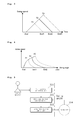
- the upper swing structure is stopped at a certain point after performing a swing operation at a predetermined angle from a corresponding stop starting time point (see FIG. 2 ).
- the upper swing structure starts deceleration at a time point where an operator releases a lever or gives a stop command, and is stopped at a certain time point after it swings at a predetermined angle. Accordingly, the stop position of the upper swing structure differs depending on the time point where the stop command starts, and thus an additional driving operation is required for the upper swing structure to reach a desired stop position.
- the present invention has been made to solve the above-mentioned problems occurring in the related art, and the subject to be solved by the present invention is to provide a swing control apparatus and a swing control method for a construction machine (particularly, an excavator), which can stop an upper swing structure of the construction machine (for example, excavator) within a predetermined range even if an operator releases a lever or gives a stop command at different time points.
- a swing control apparatus for a construction machine, including: a start position estimation unit calculating or estimating an optimum stop starting position for stopping an upper swing structure in a stop position (or at a stop angle) set by a user using the set stop position (or the set stop angle); a stop target position calculation unit calculating a stop target position using a current position of the upper swing structure and the calculated or estimated optimum stop starting position when a user's stop command is input; and a swing motor position control unit controlling a position of a swing motor so that the upper swing structure is stopped in the calculated stop target position.
- the start position estimation unit may be any one of a means for calculating the optimum stop starting position based on a mass moment of inertia and a maximum torque of the upper swing structure of the construction machine and a means for calculating the optimum stop starting position through interpolation using a lookup table that defines a mapping relation between the stop position set by the user and the stop starting position.
- stop target position calculation unit may be a means for calculating the stop target position that is determined as follows:
- stop target position (A2 ⁇ current position)/(A2 ⁇ A1)*(E2 ⁇ E1)+E1
- A2 denotes the optimum stop starting position
- A1 denotes the minimum value that is set by the user based on A2 or in consideration of a preset stop command range
- E2 denotes the stop position (or angle) set by the user
- E1 denotes the minimum position that is set by the user based on E2 or in consideration of a preset stop position range
- stop target position (A3 ⁇ current position)/(A3 ⁇ A2)*(E3 ⁇ E2)+E2,
- A3 denotes the maximum value that is set by the user based on A2 or in consideration of a preset stop command range
- E3 denotes the maximum position that is set by the user based on E2 or in consideration of a preset stop position range
- A2 denotes the optimum stop starting position
- E2 denotes the stop position (or angle) set by the user.
- a swing control method for a construction machine including: calculating or estimating an optimum stop starting position for stopping an upper swing structure in a stop position (or at a stop angle) set by a user using the set stop position (or the set stop angle); calculating a stop target position using a current position of the upper swing structure and the calculated or estimated optimum stop starting position when a user's stop command is input; and controlling the position of a swing motor so that the upper swing structure is stopped in the calculated stop target position.
- the step of calculating or estimating the stop starting position may calculate the optimum stop starting position based on a mass moment of inertia and a maximum torque of the upper swing structure of the construction machine, or calculate the optimum stop starting position through interpolation through a lookup table that defines a mapping relation between the stop position set by the user and the stop starting position.
- step of calculating the stop target position calculates the stop target position that is determined as follows:
- stop target position (A2 ⁇ current position)/(A2 ⁇ A1)*(E2 ⁇ E1)+E1
- A2 denotes the optimum stop starting position
- A1 denotes the minimum value that is set by the user based on A2 or in consideration of a preset stop command range
- E2 denotes the stop position (or angle) set by the user
- E1 denotes the minimum position that is set by the user based on E2 or in consideration of a preset stop position range
- stop target position (A3 ⁇ current position)/(A3 ⁇ A2)*(E3 ⁇ E2)+E2,
- A3 denotes the maximum value that is set by the user based on A2 or in consideration of a preset stop command range
- E3 denotes the maximum position that is set by the user based on E2 or in consideration of a preset stop position range
- A2 denotes the optimum stop starting position
- E2 denotes the stop position (or angle) set by the user.
- the optimum stop starting position for stopping the upper swing structure in the stop position (or at the stop angle) set by the user using the set stop position (or the set stop angle) is calculated or estimated
- the stop target position is calculated using the current position of the upper swing structure and the calculated or estimated optimum stop starting position when the user's stop command is input
- the position of a swing motor is controlled so that the upper swing structure is stopped in the calculated stop target position.
- the upper swing structure of the construction machine can be stopped within the range that is determined by the predetermined equation even if the operator releases the lever or gives the stop command at different time points, and thus the inconvenience can be solved which is caused by the additional driving operation that is required as the stop position differs depending on the time point where the stop command starts.
- FIGS. 1 and 2 are exemplary diagrams illustrating a general excavating work
- FIGS. 3 and 4 are diagrams schematically illustrating swing control operations in the related art
- FIG. 5 is a block diagram illustrating the configuration of a swing control apparatus for a construction machine according to an embodiment of the present invention
- FIG. 6 is a diagram schematically illustrating an aspect of calculating a stop starting position and a stop target position according to an embodiment of the present invention
- FIG. 7 is a flowchart illustrating a swing control method for a construction machine according to an embodiment of the present invention.
- FIG. 8 is a diagram schematically illustrating a swing control operation according to an embodiment of the present invention.
- FIG. 5 is a block diagram illustrating the configuration of a swing control apparatus for a construction machine according to an embodiment of the present invention.
- the swing control apparatus for a construction machine includes a start position estimation unit 301 calculating or estimating an optimum stop starting position for stopping an upper swing structure in a stop position (or at a stop angle) set by a user using the set stop position (or the set stop angle); a stop target position calculation unit 302 calculating a stop target position using a current position of the upper swing structure and the calculated or estimated optimum stop starting position when a user's stop command is input; and a swing motor position control unit 303 controlling a position of a swing motor so that the upper swing structure is stopped in the calculated stop target position.
- the start position estimation unit 301 calculates or estimates the optimum stop starting position for stopping the upper swing structure in the stop position (or angle) set by the user in the case where the user sets the stop position (or angle) of the upper swing structure.
- the detailed calculation or estimation method is as follows.
- Example 1 where the user calculates or estimates the optimum stop starting position A2 using the stop position E2 set by the user
- the optimum stop starting position is typically calculated on the basis of a mass moment of inertia and a maximum torque of the upper swing structure of a general excavator or through preparation of a lookup table by experiments and interpolation using the lookup table.
- Example 2 where the user calculates or estimates the optimum stop starting position A2 using the stop position E2 set by the user.
- the point where the stop command is actually input may be stored and used as A2.
- the stop target position calculation unit 302 calculates the stop target position using the current position of the upper swing structure and the calculated or estimated optimum stop starting position (see FIG. 6 ).
- the stop target position may be calculated as follows.
- stop target position ( A 2 ⁇ current position)/( A 2 ⁇ A 1)*( E 2 ⁇ E 1)+ E 1
- A2 denotes the optimum stop starting position
- A1 denotes the minimum value that is set by the user based on A2 or in consideration of a preset stop command range
- E2 denotes the stop position (or angle) set by the user
- E1 denotes the minimum position that is set by the user based on E2 or in consideration of a preset stop position range.
- stop target position ( A 3 ⁇ current position)/( A 3 ⁇ A 2)*( E 3 ⁇ E 2)+ E 2
- A3 denotes the maximum value that is set by the user based on A2 or in consideration of a preset stop command range
- E3 denotes the maximum position that is set by the user based on E2 or in consideration of a preset stop position range
- A2 and E2 denote the same as described above.
- the upper swing structure is controlled to be stopped at the swing point of 89 degrees.
- the swing motor position control unit 303 is installed between the stop target position calculation unit 302 and the swing motor, and if the stop target position is obtained as described above, the swing motor position control unit 303 controls the position of the swing motor so that the upper swing structure is stopped in the obtained stop target position.
- the detailed position control method is known, and the explanation thereof will be omitted.
- FIG. 7 is a flowchart illustrating the operation of the swing control apparatus for a construction machine (particularly, an excavator) according to an embodiment of the present invention.
- the stop position (or angle) of the upper swing structure is set according to the user's key operation (S 501 ).
- the optimum stop starting position for stopping the upper swing structure in the stop position (or angle) set by the user is calculated or estimated through the start position estimation unit (S 502 ).
- the optimum stop starting position may be calculated as follows.
- the optimum stop starting position is typically calculated on the basis of a mass moment of inertia and a maximum torque of the upper swing structure of a general excavator or through preparation of a lookup table by experiments and interpolation using the lookup table.
- the stop target position is calculated using the current position of the upper swing structure and the calculated or estimated optimum stop starting position through the stop target position calculation unit (S 504 and S 505 ).
- stop target position ( A 2 ⁇ current position)/( A 2 ⁇ A 1)*( E 2 ⁇ E 1)+ E 1
- A2 denotes the optimum stop starting position
- A1 denotes the minimum value that is set by the user based on A2 or in consideration of a preset stop command range
- E2 denotes the stop position (or angle) set by the user
- E1 denotes the minimum position that is set by the user based on E2 or in consideration of a preset stop position range.
- stop target position ( A 3 ⁇ current position)/( A 3 ⁇ A 2)*( E 3 ⁇ E 2)+ E 2
- A3 denotes the maximum value that is set by the user based on A2 or in consideration of a preset stop command range
- E3 denotes the maximum position that is set by the user based on E2 or in consideration of a preset stop position range
- A2 and E2 denote the same as described above.
- the position of the swing motor is controlled through the swing motor position control unit so that the upper swing structure is stopped in the obtained stop target position (S 506 ).
- the optimum stop starting position for stopping the upper swing structure in the stop position (or at the stop angle) set by the user using the set stop position (or the set stop angle) is calculated or estimated
- the stop target position is calculated using the current position of the upper swing structure and the calculated or estimated optimum stop starting position when the user's stop command is input
- the position of a swing motor is controlled so that the upper swing structure is stopped in the calculated stop target position. Accordingly, the upper swing structure can be stopped within the range that is determined by the predetermined equation even if the operator releases the lever or gives the stop command at different time points.
- the upper swing structure can be stopped within a predetermined narrowed range even if the operator releases the lever or gives the stop command at different time points (in the drawing, A1, A2, and A3), and thus the inconvenience can be solved which is caused by an additional driving operation that is required as the stop position differs depending on the time point where the stop command starts.
- the present invention can be used in the swing control apparatus for a construction machine, particularly, an excavator.
- the optimum stop starting position for stopping the upper swing structure in the stop position (or at the stop angle) set by the user using the set stop position (or the set stop angle) is calculated or estimated, the stop target position is calculated using the current position of the upper swing structure and the calculated or estimated optimum stop starting position when the user's stop command is input, and the position of a swing motor is controlled so that the upper swing structure is stopped in the calculated stop target position.
- the present invention can be used in the swing control apparatus for an excavator which can stop the upper swing structure within the determined range even if the operator releases the lever or gives the stop command at different time points.
Landscapes
- Engineering & Computer Science (AREA)
- Mining & Mineral Resources (AREA)
- Civil Engineering (AREA)
- General Engineering & Computer Science (AREA)
- Structural Engineering (AREA)
- Operation Control Of Excavators (AREA)
- Jib Cranes (AREA)
Applications Claiming Priority (1)
| Application Number | Priority Date | Filing Date | Title |
|---|---|---|---|
| PCT/KR2010/004528 WO2012008627A1 (fr) | 2010-07-13 | 2010-07-13 | Appareil de commande d'oscillation et procédé pour machine de construction |
Publications (2)
| Publication Number | Publication Date |
|---|---|
| US20130116897A1 US20130116897A1 (en) | 2013-05-09 |
| US9008919B2 true US9008919B2 (en) | 2015-04-14 |
Family
ID=45469606
Family Applications (1)
| Application Number | Title | Priority Date | Filing Date |
|---|---|---|---|
| US13/809,820 Active 2030-08-13 US9008919B2 (en) | 2010-07-13 | 2010-07-13 | Swing control apparatus and method of construction machinery |
Country Status (6)
| Country | Link |
|---|---|
| US (1) | US9008919B2 (fr) |
| EP (1) | EP2594697B1 (fr) |
| JP (1) | JP5795064B2 (fr) |
| KR (1) | KR101769484B1 (fr) |
| CN (1) | CN102985622B (fr) |
| WO (1) | WO2012008627A1 (fr) |
Cited By (2)
| Publication number | Priority date | Publication date | Assignee | Title |
|---|---|---|---|---|
| US20150176251A1 (en) * | 2012-06-04 | 2015-06-25 | Volvo Construction Equipment Ab | Driving control method for construction machine |
| US20190145082A1 (en) * | 2017-11-16 | 2019-05-16 | Caterpillar Inc. | System and method for controlling machine |
Families Citing this family (11)
| Publication number | Priority date | Publication date | Assignee | Title |
|---|---|---|---|---|
| CL2012000933A1 (es) * | 2011-04-14 | 2014-07-25 | Harnischfeger Tech Inc | Un metodo y una pala de cable para la generacion de un trayecto ideal, comprende: un motor de oscilacion, un motor de izaje, un motor de avance, un cucharon para excavar y vaciar materiales y, posicionar la pala por medio de la operacion del motor de izaje, el motor de avance y el motor de oscilacion y; un controlador que incluye un modulo generador de un trayecto ideal. |
| KR20140050031A (ko) | 2011-08-09 | 2014-04-28 | 볼보 컨스트럭션 이큅먼트 에이비 | 건설기계의 압력 제어시스템 |
| CN103857844B (zh) | 2011-10-05 | 2016-11-23 | 沃尔沃建造设备有限公司 | 用于控制使用挖掘机的土地平整工作的系统 |
| DE112013006501T5 (de) | 2013-01-24 | 2016-03-31 | Volvo Construction Equipment Ab | Vorrichtung und Verfahren zum Steuern einer Flussrate bei Baumaschinen |
| JP6511387B2 (ja) | 2015-11-25 | 2019-05-15 | 日立建機株式会社 | 建設機械の制御装置 |
| JP7070047B2 (ja) * | 2018-04-26 | 2022-05-18 | コベルコ建機株式会社 | 旋回式作業機械の旋回制御装置 |
| JP6946234B2 (ja) | 2018-04-27 | 2021-10-06 | 株式会社小松製作所 | 積込機械の制御装置および制御方法 |
| CN109914517B (zh) * | 2019-03-26 | 2022-03-11 | 吉林大学 | 一种挖掘机智能回转节能控制系统 |
| JP7141991B2 (ja) * | 2019-09-26 | 2022-09-26 | 日立建機株式会社 | 油圧ショベル |
| CN113650685B (zh) * | 2021-07-26 | 2022-11-29 | 上海三一重机股份有限公司 | 作业机械的回转控制方法、装置、电子设备及存储介质 |
| JP2026046360A (ja) * | 2024-09-02 | 2026-03-13 | 株式会社小松製作所 | 作業機械の自動旋回制御システム、作業機械、および作業機械の自動旋回制御方法 |
Citations (29)
| Publication number | Priority date | Publication date | Assignee | Title |
|---|---|---|---|---|
| JPS6233946B2 (fr) | 1979-11-28 | 1987-07-23 | Asahi Chemical Ind | |
| JPS62215733A (ja) | 1986-03-14 | 1987-09-22 | Kubota Ltd | 旋回型作業車の安全装置 |
| JPH03253914A (ja) | 1990-03-05 | 1991-11-13 | Komatsu Ltd | 教示再生式建設機械の操作装置 |
| JPH0441395B2 (fr) | 1982-05-13 | 1992-07-08 | Cerberus Ag | |
| US5259468A (en) * | 1990-10-04 | 1993-11-09 | Amoco Corporation | Method of dynamically monitoring the orientation of a curved drilling assembly and apparatus |
| EP0734993A2 (fr) * | 1995-03-31 | 1996-10-02 | Man Ghh Logistics Gmbh | Entraînement en rotation pour une grue à flêche pivotante |
| KR960013595B1 (ko) | 1992-07-27 | 1996-10-09 | 현대중장비산업 주식회사 | 건설중장비의 상부 선회체 회전각도 검출제어방법과 장치 |
| US6862509B2 (en) * | 2000-12-01 | 2005-03-01 | Putzmeister Aktiengesellschaft | Device for operating the articulated mast of a large manipulator |
| US20050166413A1 (en) * | 2003-04-28 | 2005-08-04 | Crampton Stephen J. | CMM arm with exoskeleton |
| US20050177292A1 (en) * | 2004-02-10 | 2005-08-11 | Komatsu Ltd. | Controller for work implement of construction machinery, method for controlling construction machinery, and program allowing computer to execute this method |
| EP1813728A1 (fr) * | 2004-11-17 | 2007-08-01 | Komatsu Ltd | Dispositif de contrôle d'oscillation et machine de construction |
| EP1914353A2 (fr) * | 2006-10-19 | 2008-04-23 | Hitachi Construction Machinery Co., Ltd. | Engin de construction |
| US20080164832A1 (en) * | 2004-11-17 | 2008-07-10 | Komatsu Ltd. | Rotation Control Device and Construction Machine |
| KR20080099749A (ko) | 2007-05-10 | 2008-11-13 | 볼보 컨스트럭션 이키프먼트 홀딩 스웨덴 에이비 | 굴삭기의 작업장치 제어장치 및 제어방법 |
| EP2071085A2 (fr) * | 2007-12-13 | 2009-06-17 | Volvo Construction Equipment Holding Sweden AB | Système de commande de mise à niveau manuelle et procédé de construction d'équipement |
| US7574821B2 (en) * | 2004-09-01 | 2009-08-18 | Siemens Energy & Automation, Inc. | Autonomous loading shovel system |
| US7753132B2 (en) * | 2006-11-30 | 2010-07-13 | Caterpillar Inc | Preparation for machine repositioning in an excavating operation |
| US20100264106A1 (en) * | 2009-04-17 | 2010-10-21 | Kabushiki Kaisha Kobe Seiko Sho (Kobe Steel Ltd.) | Slewing stop control apparatus and method for slewing type working machine |
| US20110029206A1 (en) * | 2009-07-28 | 2011-02-03 | Volvo Construction Equipment Holding Sweden Ab. | Swing control system and method for construction machine using electric motor |
| US20110106384A1 (en) * | 2008-06-16 | 2011-05-05 | Commonwealth Scientific And Industrial Research Organisation | Method and system for machinery control |
| US20120082536A1 (en) * | 2009-06-09 | 2012-04-05 | Sumitomo Heavy Industries, Ltd. | Hybrid excavator and method of controlling hybrid excavator |
| US8190334B2 (en) * | 2007-02-21 | 2012-05-29 | Kobelco Construction Machinery Co., Ltd. | Rotation control device and working machine therewith |
| US8204653B2 (en) * | 2007-02-21 | 2012-06-19 | Deere & Company | Automated control of boom and attachment for work vehicle |
| US20130051963A1 (en) * | 2011-08-30 | 2013-02-28 | Wesley P. Taylor | Systems, methods, and devices for controlling a movement of a dipper |
| US20130075156A1 (en) * | 2011-09-20 | 2013-03-28 | Giovanni Casadei | Control System for a Machine for Digging and/or Drilling Soil and Digging and/or Drilling Machine Including Such a System |
| US8437923B2 (en) * | 2008-05-29 | 2013-05-07 | Sumitomo(S.H.I) Construction Machinery Co., Ltd. | Rotation drive control unit and construction machine including same |
| US20130234642A1 (en) * | 2010-12-20 | 2013-09-12 | Mitsubishi Electric Corporation | Motor control device |
| US8818649B2 (en) * | 2009-06-25 | 2014-08-26 | Hitachi Construction Machinery Co., Ltd. | Rotation control device for working machine |
| US20140336882A1 (en) * | 2012-07-16 | 2014-11-13 | Flanders Electric Motor Service, Inc. | Optimized bank penetration method |
Family Cites Families (3)
| Publication number | Priority date | Publication date | Assignee | Title |
|---|---|---|---|---|
| JP2744117B2 (ja) * | 1990-06-05 | 1998-04-28 | 株式会社神戸製鋼所 | クレーン等の旋回制御装置 |
| US6363632B1 (en) * | 1998-10-09 | 2002-04-02 | Carnegie Mellon University | System for autonomous excavation and truck loading |
| JP4475301B2 (ja) * | 2007-08-03 | 2010-06-09 | ダイキン工業株式会社 | 旋回体の駆動制御装置 |
-
2010
- 2010-07-13 CN CN201080068018.5A patent/CN102985622B/zh active Active
- 2010-07-13 US US13/809,820 patent/US9008919B2/en active Active
- 2010-07-13 WO PCT/KR2010/004528 patent/WO2012008627A1/fr not_active Ceased
- 2010-07-13 KR KR1020127033041A patent/KR101769484B1/ko active Active
- 2010-07-13 EP EP10854749.8A patent/EP2594697B1/fr active Active
- 2010-07-13 JP JP2013519559A patent/JP5795064B2/ja not_active Expired - Fee Related
Patent Citations (30)
| Publication number | Priority date | Publication date | Assignee | Title |
|---|---|---|---|---|
| JPS6233946B2 (fr) | 1979-11-28 | 1987-07-23 | Asahi Chemical Ind | |
| JPH0441395B2 (fr) | 1982-05-13 | 1992-07-08 | Cerberus Ag | |
| JPS62215733A (ja) | 1986-03-14 | 1987-09-22 | Kubota Ltd | 旋回型作業車の安全装置 |
| JPH03253914A (ja) | 1990-03-05 | 1991-11-13 | Komatsu Ltd | 教示再生式建設機械の操作装置 |
| US5259468A (en) * | 1990-10-04 | 1993-11-09 | Amoco Corporation | Method of dynamically monitoring the orientation of a curved drilling assembly and apparatus |
| KR960013595B1 (ko) | 1992-07-27 | 1996-10-09 | 현대중장비산업 주식회사 | 건설중장비의 상부 선회체 회전각도 검출제어방법과 장치 |
| EP0734993A2 (fr) * | 1995-03-31 | 1996-10-02 | Man Ghh Logistics Gmbh | Entraînement en rotation pour une grue à flêche pivotante |
| US6862509B2 (en) * | 2000-12-01 | 2005-03-01 | Putzmeister Aktiengesellschaft | Device for operating the articulated mast of a large manipulator |
| US20050166413A1 (en) * | 2003-04-28 | 2005-08-04 | Crampton Stephen J. | CMM arm with exoskeleton |
| US20080235970A1 (en) * | 2003-04-28 | 2008-10-02 | Stephen James Crampton | CMM Arm With Exoskeleton |
| US20050177292A1 (en) * | 2004-02-10 | 2005-08-11 | Komatsu Ltd. | Controller for work implement of construction machinery, method for controlling construction machinery, and program allowing computer to execute this method |
| US7574821B2 (en) * | 2004-09-01 | 2009-08-18 | Siemens Energy & Automation, Inc. | Autonomous loading shovel system |
| EP1813728A1 (fr) * | 2004-11-17 | 2007-08-01 | Komatsu Ltd | Dispositif de contrôle d'oscillation et machine de construction |
| US20080164832A1 (en) * | 2004-11-17 | 2008-07-10 | Komatsu Ltd. | Rotation Control Device and Construction Machine |
| EP1914353A2 (fr) * | 2006-10-19 | 2008-04-23 | Hitachi Construction Machinery Co., Ltd. | Engin de construction |
| US7753132B2 (en) * | 2006-11-30 | 2010-07-13 | Caterpillar Inc | Preparation for machine repositioning in an excavating operation |
| US8190334B2 (en) * | 2007-02-21 | 2012-05-29 | Kobelco Construction Machinery Co., Ltd. | Rotation control device and working machine therewith |
| US8204653B2 (en) * | 2007-02-21 | 2012-06-19 | Deere & Company | Automated control of boom and attachment for work vehicle |
| KR20080099749A (ko) | 2007-05-10 | 2008-11-13 | 볼보 컨스트럭션 이키프먼트 홀딩 스웨덴 에이비 | 굴삭기의 작업장치 제어장치 및 제어방법 |
| EP2071085A2 (fr) * | 2007-12-13 | 2009-06-17 | Volvo Construction Equipment Holding Sweden AB | Système de commande de mise à niveau manuelle et procédé de construction d'équipement |
| US8437923B2 (en) * | 2008-05-29 | 2013-05-07 | Sumitomo(S.H.I) Construction Machinery Co., Ltd. | Rotation drive control unit and construction machine including same |
| US20110106384A1 (en) * | 2008-06-16 | 2011-05-05 | Commonwealth Scientific And Industrial Research Organisation | Method and system for machinery control |
| US20100264106A1 (en) * | 2009-04-17 | 2010-10-21 | Kabushiki Kaisha Kobe Seiko Sho (Kobe Steel Ltd.) | Slewing stop control apparatus and method for slewing type working machine |
| US20120082536A1 (en) * | 2009-06-09 | 2012-04-05 | Sumitomo Heavy Industries, Ltd. | Hybrid excavator and method of controlling hybrid excavator |
| US8818649B2 (en) * | 2009-06-25 | 2014-08-26 | Hitachi Construction Machinery Co., Ltd. | Rotation control device for working machine |
| US20110029206A1 (en) * | 2009-07-28 | 2011-02-03 | Volvo Construction Equipment Holding Sweden Ab. | Swing control system and method for construction machine using electric motor |
| US20130234642A1 (en) * | 2010-12-20 | 2013-09-12 | Mitsubishi Electric Corporation | Motor control device |
| US20130051963A1 (en) * | 2011-08-30 | 2013-02-28 | Wesley P. Taylor | Systems, methods, and devices for controlling a movement of a dipper |
| US20130075156A1 (en) * | 2011-09-20 | 2013-03-28 | Giovanni Casadei | Control System for a Machine for Digging and/or Drilling Soil and Digging and/or Drilling Machine Including Such a System |
| US20140336882A1 (en) * | 2012-07-16 | 2014-11-13 | Flanders Electric Motor Service, Inc. | Optimized bank penetration method |
Non-Patent Citations (3)
| Title |
|---|
| International Preliminary Report on Patentability (Chapter II of the Patent Cooperation Treaty) in Korean for PCT/KR2010/004528; dated Nov. 21, 2012; IPEA/KR. |
| International Search Report (in Korean and English) and Written Opinion (in Korean) for PCT/KR2010/004528, mailed Apr. 26, 2011; ISA/KR. |
| Office Action dated Sep. 30, 2014 in corresponding JP2013-519559. |
Cited By (4)
| Publication number | Priority date | Publication date | Assignee | Title |
|---|---|---|---|---|
| US20150176251A1 (en) * | 2012-06-04 | 2015-06-25 | Volvo Construction Equipment Ab | Driving control method for construction machine |
| US9562345B2 (en) * | 2012-06-04 | 2017-02-07 | Volvo Construction Equipment Ab | Driving control method for construction machine |
| US20190145082A1 (en) * | 2017-11-16 | 2019-05-16 | Caterpillar Inc. | System and method for controlling machine |
| US10519626B2 (en) * | 2017-11-16 | 2019-12-31 | Caterpillar Inc. | System and method for controlling machine |
Also Published As
| Publication number | Publication date |
|---|---|
| EP2594697A1 (fr) | 2013-05-22 |
| WO2012008627A1 (fr) | 2012-01-19 |
| KR101769484B1 (ko) | 2017-08-18 |
| EP2594697B1 (fr) | 2021-12-15 |
| KR20130124160A (ko) | 2013-11-13 |
| CN102985622A (zh) | 2013-03-20 |
| EP2594697A4 (fr) | 2018-02-14 |
| CN102985622B (zh) | 2016-03-09 |
| US20130116897A1 (en) | 2013-05-09 |
| JP5795064B2 (ja) | 2015-10-14 |
| JP2013535593A (ja) | 2013-09-12 |
Similar Documents
| Publication | Publication Date | Title |
|---|---|---|
| US9008919B2 (en) | Swing control apparatus and method of construction machinery | |
| CN108138460B (zh) | 工程机械 | |
| EP2281953A2 (fr) | Système de contrôle d'oscillation et procédé de machine de construction utilisant un moteur électrique | |
| US9822510B2 (en) | Construction machine | |
| EP2653619B1 (fr) | Système de commande de pivotement destiné à un engin de construction hybride | |
| US9725882B2 (en) | Device and method for controlling flow rate in construction machinery | |
| JP2021156030A (ja) | 作業機械の遠隔操縦システム | |
| EP2208631A1 (fr) | Système de contrôle du régime de moteur pour machine de construction | |
| CA2978389C (fr) | Systeme et methode de controle semi-autonome d'une machine industrielle | |
| US20170016460A1 (en) | Device for controlling regenerated flow rate for construction machine and method for controlling same | |
| JP2003328398A (ja) | 作業機械の旋回制御装置 | |
| WO2015114909A1 (fr) | Système de soutien aux opérations pour engin de chantier | |
| WO2016024642A1 (fr) | Dispositif de commande de moteur pour engin de chantier hybride, engin de chantier hybride, et procédé de commande de moteur pour engin de chantier hybride | |
| JP2011078277A (ja) | 電動式建設機械 | |
| US9562345B2 (en) | Driving control method for construction machine | |
| EP2796623B1 (fr) | Appareil pour établir un degré d'aptitude à la commande pour un engin de chantier | |
| JP2007085093A (ja) | 建設機械のフロント制御装置 | |
| JP5345594B2 (ja) | 油圧装置 | |
| US11613872B2 (en) | Slewing control device for construction machine | |
| CN109698654B (zh) | 一种控制自动离合器执行电机的方法和装置 | |
| JP5398647B2 (ja) | ハイブリッド式建設機械 | |
| JP2015220857A (ja) | 回転アクチュエータの駆動方法および駆動制御装置 | |
| JP2014510212A (ja) | ハイブリッド掘削機の電気式旋回システムにおけるアンチリバウンド制御装置及びその制御方法 | |
| JP2010001714A (ja) | 駆動制御装置及びこれを含む建設機械 | |
| JP2001303622A (ja) | 油圧ショベルのフロント制御装置 |
Legal Events
| Date | Code | Title | Description |
|---|---|---|---|
| AS | Assignment |
Owner name: VOLVO CONSTRUCTION EQUIPMENT AB, SWEDEN Free format text: ASSIGNMENT OF ASSIGNORS INTEREST;ASSIGNORS:LEE, CHUN-HAN;KIM, JIN-SEOP;REEL/FRAME:029615/0976 Effective date: 20130107 |
|
| FEPP | Fee payment procedure |
Free format text: PAYOR NUMBER ASSIGNED (ORIGINAL EVENT CODE: ASPN); ENTITY STATUS OF PATENT OWNER: LARGE ENTITY |
|
| STCF | Information on status: patent grant |
Free format text: PATENTED CASE |
|
| MAFP | Maintenance fee payment |
Free format text: PAYMENT OF MAINTENANCE FEE, 4TH YEAR, LARGE ENTITY (ORIGINAL EVENT CODE: M1551); ENTITY STATUS OF PATENT OWNER: LARGE ENTITY Year of fee payment: 4 |
|
| MAFP | Maintenance fee payment |
Free format text: PAYMENT OF MAINTENANCE FEE, 8TH YEAR, LARGE ENTITY (ORIGINAL EVENT CODE: M1552); ENTITY STATUS OF PATENT OWNER: LARGE ENTITY Year of fee payment: 8 |