US9116530B2 - Transport refrigeration security system - Google Patents
Transport refrigeration security system Download PDFInfo
- Publication number
- US9116530B2 US9116530B2 US13/816,639 US201113816639A US9116530B2 US 9116530 B2 US9116530 B2 US 9116530B2 US 201113816639 A US201113816639 A US 201113816639A US 9116530 B2 US9116530 B2 US 9116530B2
- Authority
- US
- United States
- Prior art keywords
- controller
- sensor
- security
- monitor system
- battery
- Prior art date
- Legal status (The legal status is an assumption and is not a legal conclusion. Google has not performed a legal analysis and makes no representation as to the accuracy of the status listed.)
- Expired - Fee Related
Links
Images



Classifications
-
- G—PHYSICS
- G05—CONTROLLING; REGULATING
- G05F—SYSTEMS FOR REGULATING ELECTRIC OR MAGNETIC VARIABLES
- G05F5/00—Systems for regulating electric variables by detecting deviations in the electric input to the system and thereby controlling a device within the system to obtain a regulated output
-
- B—PERFORMING OPERATIONS; TRANSPORTING
- B60—VEHICLES IN GENERAL
- B60R—VEHICLES, VEHICLE FITTINGS, OR VEHICLE PARTS, NOT OTHERWISE PROVIDED FOR
- B60R25/00—Fittings or systems for preventing or indicating unauthorised use or theft of vehicles
- B60R25/10—Fittings or systems for preventing or indicating unauthorised use or theft of vehicles actuating a signalling device
-
- G—PHYSICS
- G07—CHECKING-DEVICES
- G07C—TIME OR ATTENDANCE REGISTERS; REGISTERING OR INDICATING THE WORKING OF MACHINES; GENERATING RANDOM NUMBERS; VOTING OR LOTTERY APPARATUS; ARRANGEMENTS, SYSTEMS OR APPARATUS FOR CHECKING NOT PROVIDED FOR ELSEWHERE
- G07C5/00—Registering or indicating the working of vehicles
- G07C5/08—Registering or indicating performance data other than driving, working, idle, or waiting time, with or without registering driving, working, idle or waiting time
- G07C5/0841—Registering performance data
- G07C5/085—Registering performance data using electronic data carriers
- G07C5/0858—Registering performance data using electronic data carriers wherein the data carrier is removable
-
- G—PHYSICS
- G08—SIGNALLING
- G08B—SIGNALLING SYSTEMS, e.g. PERSONAL CALLING SYSTEMS; ORDER TELEGRAPHS; ALARM SYSTEMS
- G08B23/00—Alarms responsive to unspecified undesired or abnormal conditions
-
- G—PHYSICS
- G08—SIGNALLING
- G08B—SIGNALLING SYSTEMS, e.g. PERSONAL CALLING SYSTEMS; ORDER TELEGRAPHS; ALARM SYSTEMS
- G08B29/00—Checking or monitoring of signalling or alarm systems; Prevention or correction of operating errors, e.g. preventing unauthorised operation
- G08B29/18—Prevention or correction of operating errors
- G08B29/181—Prevention or correction of operating errors due to failing power supply
-
- G—PHYSICS
- G08—SIGNALLING
- G08G—TRAFFIC CONTROL SYSTEMS
- G08G1/00—Traffic control systems for road vehicles
- G08G1/20—Monitoring the location of vehicles belonging to a group, e.g. fleet of vehicles, countable or determined number of vehicles
Definitions
- the present disclosure generally relates to transport units, and more particularly, to security systems and methods for monitoring transport refrigeration units.
- Security systems are well known in the art and commonly used to monitor various parameters of transport refrigeration units and the cargo carried therein.
- Such security systems provide security sensors that are configured to, for instance, determine the status of one or more doors of the transport unit and monitor the level of fuel in the transport unit. Using these sensors, it is possible to detect unauthorized access to the cargo and/or detect critical levels of fuel so as to provide the appropriate alerts and inform those responsible of the transport unit or cargo. More specifically, the data provided by the security sensors can be transmitted to a remote monitoring facility, stored at a local data recorder for later retrieval, or used by the control system to trigger an alarm if the data indicates atypical and/or unfavorable events. Although these control systems offer some level of security, there are still some significant deficiencies.
- DC direct current
- these control systems are typically switched to the ignition system of the transport unit such that DC power is only supplied while the engine, alternator and/or the battery of the transport unit is powered on.
- the ignition is switched off, however, the power supplied to the control system as well as most other vehicle accessories is disabled.
- the control system is disabled, its security sensors are unable to detect a fault condition in which, for example, a door has been opened without authorization. In such a way, even with such security measures, transport units are still vulnerable to theft, vandalism, and the like, when they are powered off and/or left unattended.
- some existing control systems provide periodic monitoring while the transport unit is powered off. These control systems are configured to enter a sleep mode when the transport unit is turned off, during which the security sensor data are monitored and/or recorded at predetermined wake up intervals rather than being continuously on.
- the wake up intervals are generally long, lasting anywhere between 15 minutes to an hour, so as to conserve battery power and memory space. Any fault condition which occurs during these intervals can only be detected at the next wake up instance resulting in a delayed rather than an immediate response.
- a person can easily disconnect the battery, disable power to the security sensors and access the cargo without triggering any alarm. Accordingly, while wake up circuits provide some added security, transport refrigeration units are still vulnerable to theft when they are powered off and/or unattended.
- an energy conserving security monitor system for a transport unit.
- the security monitor system may include at least one input device configured to receive an input signal for selectively performing a function on the transport unit, and a controller having a plurality of inputs, a plurality of outputs, and a low power control circuit.
- the low power circuit may provide electrical communication between a battery of the transport unit, the input device, and at least one of the inputs of the controller.
- the control circuit may be configured to maintain the controller in low power mode when the input signal is not indicative of performing a function on the transport unit.
- the control circuit may be configured to enable power to the controller when the input signal is indicative of performing a function on the transport unit.
- a security monitor system for a transport unit.
- the security monitor system may include at least one security sensor configured to detect a fault condition, and a controller having a plurality of inputs, a plurality of outputs, and a low power control circuit.
- the low power circuit may provide electrical communication between a battery of the transport unit, the security sensor, and at least one of the inputs of the controller.
- the control circuit may be configured to maintain the controller in low power mode when there are no detected fault conditions.
- the control circuit may be configured to enable power to the controller when there is a detected fault condition.
- the security monitor system may include at least one door switch configured to detect unauthorized access to the transport refrigeration unit, and a controller having a plurality of inputs, a plurality of outputs, and a low power control circuit.
- the low power control circuit may provide electrical communication between a battery of the transport refrigeration unit, the door switch, and at least one of the inputs of the controller.
- the control circuit may be configured to maintain the controller in low power mode when there are no detected fault conditions.
- the control circuit may be configured to enable power to the controller when there is a detected fault condition.
- a method for conserving energy in a transport unit may provide an input device configured to receive an input signal and selectively perform a function on the transport unit based on the input signal, provide a low power control circuit in communication between a battery of the transport unit, the input device and at least one of the inputs of the controller, maintain the controller in low power mode when the input signal is not indicative of performing a function on the transport unit, and automatically enable power to the controller when the input signal is indicative of performing a function on the transport unit.
- the low power control circuit may be configured to bias a controller into a low power mode of operation.
- FIG. 1 is a schematic diagram of an exemplary security monitor system as applied to a transport refrigeration unit
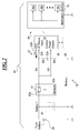
- FIG. 2 is a schematic diagram of another exemplary security monitor system.
- FIG. 3 is flow diagram of an exemplary method for monitoring a transport refrigeration unit.
- an exemplary security monitor system for a transport refrigeration unit is provided and referred to as reference number 10 . It is understood that the teachings of the disclosure may be used to construct security monitor systems for transport units above and beyond those specifically disclosed below. One of ordinary skill in the art will readily understand that the following are only exemplary embodiments.
- FIGS. 1-2 schematics of exemplary low power security monitor systems 10 that may be installed in a transport refrigeration unit are provided.
- the security monitor systems 10 disclosed herein may also be integrated into other types of transport units, such as trailers, freight containers, trucks, rail cars, and the like.
- the security monitor systems 10 may be provided to any transport unit which requires continuous monitoring of one or more parameters thereof but is limited to a portable energy source, such as a battery or a fuel tank with a capacity that is restricted to what the transport unit can carry or support.
- an exemplary security monitor system 10 may essentially include one or more input devices 11 , such as security sensors 12 , a controller 14 , notification devices 16 , and a low power control circuit 18 for electrically coupling these components to a power source of the transport unit, such as a battery 20 , or the like.
- the input devices 11 may be associated with an auxiliary or accessory device of the transport unit and configured to receive an input signal from an operator and/or owner of the transport unit.
- the auxiliary or accessory devices associated with the input devices 11 may include, for example, a refrigeration unit, a heating, ventilation and air-conditioning (HVAC) system, a lighting unit, or any other accessory that may receive power from the battery 20 and/or fuel combustion.
- HVAC heating, ventilation and air-conditioning
- the controller 14 may be selectively perform an auxiliary or accessory function on the transport unit, such as operating a portable refrigeration unit, operating the HVAC system, providing light, and the like.
- the input devices 11 may also include security sensors 12 that are configured to observe various security parameters of the transport unit while the controller 14 monitors the observed parameters for fault conditions. If a fault condition is determined by the controller 14 , the appropriate notification devices 16 may alert and notify the users and/or owners of the transport unit of the fault condition. Furthermore, the low power configuration of the control circuit 18 may ensure that the controller 14 is only engaged when it is needed, for example, when a potential fault is detected at the security sensors 12 . Such a low power configuration essentially eliminates the amount of time the controller 14 is needlessly online, and thus, greatly reduces the power consumed by the controller 14 . By reducing the amount of energy needed to operate the controller 14 , the charge in the battery 20 is greatly conserved, and among other things, fuel consumption may be significantly reduced.
- the security sensors 12 of FIGS. 1-2 may include one or more sensors that are configured to detect fault conditions, or critical changes to the transport unit that may be indicative of unauthorized access, theft, vandalism, malfunction of the transport unit, or any other abnormal or undesired activity.
- the security sensors 12 may include a discrete sensor, such as a door switch 12 a that is capable of determining when a cargo door of the transport unit is opened or closed.
- the door switch 12 a may be a normally closed switch which allows flow of current therethrough when all of the doors of the transport unit are closed. When at least one cargo door is opened, the normally closed door switch 12 a may open to break the flow of current.
- the door switch 12 a may also be a normally opened switch, as shown in FIG. 2 , which prohibits flow of current therethrough when all of the doors are closed. When at least one cargo door is opened, the normally opened switch 12 a may close to enable flow of current therethrough.
- the security sensors 12 may also include an analog sensor, such as a fuel level sensor 12 b which outputs a continuous analog signal that is indicative of the level of fuel in the transport unit. Based on such feedback, a corresponding controller 14 may be able to monitor for a critically low level of fuel and/or for a critically high rate of reduction in fuel.
- the security sensors 12 may include a battery voltage sensor and/or battery connection sensor that is configured to detect when the battery voltage level drops to a critical minimum and/or detect when the battery 20 is disconnected.
- the security sensors 12 may additionally include one or more of a temperature sensor, pressure sensor, a humidity sensor, a movement sensor, an impact sensor, a tilt sensor, and the like.
- the controller 14 of the security monitor system 10 may be implemented using one or more of a processor, a microprocessor, a microcontroller, an electronic control module (ECM), an electronic control unit (ECU), or any other suitable means for electronically controlling functionality of the security monitor system 10 .
- the controller 14 may include a plurality of inputs 22 for receiving discrete and/or analog electronic signals as well as a plurality of outputs 24 for transmitting discrete and/or analog electronic signals to other auxiliary, accessory or periphery devices, such as the notification devices 16 shown.
- the controller 14 may include at least a power enabling input 22 a and a reference voltage input 22 b . Based on the input voltage received at the power enabling input 22 a , the controller 14 may be powered off, powered on, placed in low power mode, placed in sleep mode, or the like. For example, the controller 14 may be configured to automatically power on if the electrical signal provided to the power enabling input 22 a corresponds to approximately 5 VDC, 10 VDC, 15 VDC, or any other direct current (DC) reference voltage corresponding to a logical high value.
- the appropriate reference voltage may be determined in accordance with the voltage value provided to the reference voltage input 22 b of the controller 14 .
- the reference voltage may also be determined based on the respective specifications of the battery 20 of the transport unit, the resistance values R 1 -R 5 provided by the low power control circuit 18 , and the like.
- the controller 14 may also be powered off if the voltage at the power enabling input 22 a is less than a predetermined minimum voltage to conserve energy. For instance, if the voltage supplied to the power enabling input 22 a is approximately 0 VDC or corresponding to a logical low value, the controller 14 may automatically power off and remain powered off until the next logical high value is received. In alternative embodiments, the controller 14 may provide a power enabling input 22 a that is inverted, in which case voltage supplied to the power enabling input 22 a corresponding a logical low value may be used to power on the controller 14 while a voltage corresponding to a logical high value may be used to power off the controller 14 .
- the controller 14 may additionally operate in a low power mode of operation or a sleep mode so as to conserve battery power or fuel.
- Low power or sleep modes may enable the controller 14 to operate on minimal battery power while still allowing some functionality thereof, such as the monitoring of security sensors 12 .
- the voltage provided at the power enabling input 22 a may be within a predetermined range of relatively low voltages.
- the range of voltages corresponding to low power mode may be higher in magnitude than 0 VDC but lower in magnitude than the reference voltage provided, for example, 5 VDC, 10 VDC, 15 VDC, or the like.
- the controller 14 may be configured to enter a low power mode or sleep mode by its own determination based on different criteria preprogrammed therein.
- Low power mode or sleep mode may also be induced on the controller 14 by adjusting the voltage supplied thereto.
- the controller 14 may further include a status input 22 c by which the controller 14 may determine the desired or current mode of operation based on, for example, the magnitude of the voltage detected at the status input 22 c.
- the controller 14 may generate one or more signals at its outputs 24 to be transmitted to one or more auxiliary, accessory or periphery devices of the transport unit, such as the notification devices 16 shown.
- the notification devices 16 may include one or more of an audible device 16 a , a visual device 16 b , and the like.
- the audible device 16 a may include a ringer, a buzzer, or any other device that can produce an audible alert and call attention to the transport unit.
- the visual device 16 b may include blinking light emitting diodes (LEDs), screen activity on a liquid crystal display (LCD), or any other form of visual alert that may call attention to the transport unit.
- Each of the audible device 16 a and the visual device 16 b may be provided in the vicinity of the transport unit and/or at a remote monitoring location.
- the notification device 16 may also employ a telematic device 16 c that is configured to generate an alert to the appropriate users and/or owners of the transport unit via cellular networks, satellite communications, and the like. More specifically, the controller 14 and the telematic device 16 c may generate a fault code, a text message, electronic mail message, or the like, and further, transmit the code or message to the pager, cellular device or computer of the respective users and/or owners.
- the code or message may simply indicate that a fault condition has been detected, or provide further details of the detected fault, such as the type of fault, the frequency or duration of the fault, possible solutions for correcting the fault, and the like.
- the low power control circuit 18 may be configured to interconnect each of the security sensors 12 , controller 14 , notification devices 16 and the battery 20 so as to enable the security monitor system 10 to fully operate on minimal power from the battery 20 and on minimal fuel. More specifically, the control circuit 18 may be configured such that the discrete security sensors 12 , such as door switches 12 a , enable or disable an electrical connection between the power enabling input 22 a of the controller 14 and the battery 20 based on the state of the security sensors 12 . In embodiments in which analog sensors, such as fuel level sensors 12 b , are employed, the low power control circuit 18 and controller 14 may be configured to enable monitoring of the analog sensor while in a low power mode of operation.
- the low power control circuit 18 may be configured to electrically couple the power enabling input 22 a of the controller 14 to ground while the door switch 12 a is closed.
- the controller 14 may be provided with a logical low voltage value so as leave the controller 14 powered off or in a low power mode when there are no faults present.
- the power enabling input 22 a of the controller 14 may be disconnected from ground and provided with a logically high voltage value from the positive terminal of the battery 20 .
- the low power control circuit 18 may be configured to electrically couple the power enabling input 22 a of the controller 14 to ground while the door switch 12 a is opened.
- the controller 14 may be provided with a logical low voltage value so as leave the controller 14 powered off or in a low power mode when there are no faults present.
- the power enabling input 22 a of the controller 14 may be provided with a logically high voltage value from the positive terminal of the battery 20 .
- the controller 14 may automatically wake up from the low power mode and power on. The controller 14 may then determine whether the detected fault condition, or the opening of cargo doors, was an authorized or an unauthorized event. If the fault condition is confirmed to be an authorized event, the controller 14 may simply ignore the fault, return to low power or sleep mode and continue monitoring the security sensors 12 . If the fault condition is confirmed to be an undesired or unauthorized event, the controller 14 may generate the appropriate signals to be transmitted to the notification devices 16 . Based on the signals received from the controller 14 , for example, one or more of the audible device 16 a , visual device 16 b and telematic device 16 c may be engaged to alert the users and/or owners of the transport unit.
- the controller 14 may further be configured to automatically record any or all data pertaining to the transport unit in response to the detected fault.
- the recorded data may be stored in a memory 26 , 28 for later retrieval and review.
- the manner in which the controller 14 responds to a detected fault condition may be configurable by the user and/or owner of the transport unit. For example, a user or owner may enable or disable one or more of the notification devices 16 that are set to engage for a particular fault type. A user or owner may also adjust the types of data to record, duration of the recording, interval of the recording or disable the data recording feature.
- the low power control circuit 18 may also provide electrical communication with a backup battery 30 .
- a secondary battery 30 may be coupled to the security sensors 12 , the controller 14 and the notification devices 16 through an auxiliary and/or a parallel connection therewith.
- the auxiliary connection may further be automatically switched such that the backup battery 30 is only coupled to the security monitor system 10 if the primary battery 20 is disconnected.
- the security sensors 12 may employ a battery connection sensor for monitoring the connection to the primary battery 20 .
- the controller 14 may conserve energy while monitoring a transport unit.
- the controller 14 may be preprogrammed with an algorithm or a set of program codes to perform according to the method shown.
- the algorithm may be stored within an on-board or internal memory 26 of the controller 14 and/or on an external memory 28 that is in communication with the controller 14 .
- the external memory 28 may take the form of, for example, a floppy disk, a hard disk, optical medium, random access memory (RAM), read-only memory (ROM), or any other suitable computer-readable storage medium commonly used in the art.
- the method of FIG. 3 may include a step of providing at least one security sensor 12 that is configured to detect a fault condition within a transport unit.
- the method may also enable electrical communication between the battery 20 of the transport unit, the security sensor 12 and the inputs 22 of the controller 14 using a low power control circuit 18 .
- the low power control circuit 18 may be configured to bias the controller 14 into a low power mode of operation so as to conserve battery power.
- the method may further monitor for any faults detected by the security sensor 12 . If no faults are detected, the method may continue to maintain the controller 14 in low power mode.
- the method may automatically direct power from the battery 20 to a power enabling input 22 a of the controller 14 so as to wake the controller 14 up from the low power mode and to allow the controller 14 to respond to the detected fault accordingly.
- the method may further generate an alert, for example, using one of the notification devices 16 of FIGS. 1-2 , so as to notify a user and/or owner of the transport unit of the detected fault condition.
- the method may record various data from the transport unit for a predefined period of time in response to the detected fault condition.
- the present disclosure provides more comprehensive monitoring of a transport refrigeration unit with several advantages over currently existing security configurations built for transport units. Moreover, the present disclosure provides continuous monitoring of various parameters of a transport unit for extended periods of time without being limited to the operation state of the transport unit. Furthermore, the present disclosure provides such continuous monitoring schemes while, among other things, significantly conserving battery charge and fuel.
Landscapes
- Engineering & Computer Science (AREA)
- Physics & Mathematics (AREA)
- General Physics & Mathematics (AREA)
- Electromagnetism (AREA)
- Radar, Positioning & Navigation (AREA)
- Automation & Control Theory (AREA)
- Computer Security & Cryptography (AREA)
- Mechanical Engineering (AREA)
- Business, Economics & Management (AREA)
- Emergency Management (AREA)
- Devices That Are Associated With Refrigeration Equipment (AREA)
- Alarm Systems (AREA)
Priority Applications (1)
| Application Number | Priority Date | Filing Date | Title |
|---|---|---|---|
| US13/816,639 US9116530B2 (en) | 2010-08-13 | 2011-08-11 | Transport refrigeration security system |
Applications Claiming Priority (3)
| Application Number | Priority Date | Filing Date | Title |
|---|---|---|---|
| US37350710P | 2010-08-13 | 2010-08-13 | |
| PCT/US2011/047388 WO2012021685A1 (en) | 2010-08-13 | 2011-08-11 | Transport refrigeration security system |
| US13/816,639 US9116530B2 (en) | 2010-08-13 | 2011-08-11 | Transport refrigeration security system |
Publications (2)
| Publication Number | Publication Date |
|---|---|
| US20130147624A1 US20130147624A1 (en) | 2013-06-13 |
| US9116530B2 true US9116530B2 (en) | 2015-08-25 |
Family
ID=44789579
Family Applications (1)
| Application Number | Title | Priority Date | Filing Date |
|---|---|---|---|
| US13/816,639 Expired - Fee Related US9116530B2 (en) | 2010-08-13 | 2011-08-11 | Transport refrigeration security system |
Country Status (4)
| Country | Link |
|---|---|
| US (1) | US9116530B2 (de) |
| EP (1) | EP2603401A1 (de) |
| CN (1) | CN103038099A (de) |
| WO (1) | WO2012021685A1 (de) |
Cited By (1)
| Publication number | Priority date | Publication date | Assignee | Title |
|---|---|---|---|---|
| US20180089982A1 (en) * | 2016-09-23 | 2018-03-29 | EMC IP Holding Company LLC | Method, device, and system for fault unit indication |
Families Citing this family (9)
| Publication number | Priority date | Publication date | Assignee | Title |
|---|---|---|---|---|
| US20140018015A1 (en) * | 2012-03-21 | 2014-01-16 | Robertshaw Controls Company | Methods and systems for preserving the power source life of a wireless end node prior to deployment in a transport refrigeration system |
| WO2013165995A1 (en) * | 2012-04-30 | 2013-11-07 | Thermo King Corporation | Transport refrigeration system controller to engine control unit interface |
| WO2013188888A1 (en) * | 2012-06-14 | 2013-12-19 | Thermo King Corporation | Methods and systems for power management of a transport refrigeration system |
| JP6492436B2 (ja) * | 2014-07-17 | 2019-04-03 | 富士通株式会社 | センサ装置及びモニタリング方法 |
| US20190105964A1 (en) * | 2016-03-24 | 2019-04-11 | Carrier Corporation | Abuse detection for transport refrigeration units |
| US20190315264A1 (en) * | 2016-11-21 | 2019-10-17 | Carrier Corporation | Landing gear system, landing gear security system, and method of operating a landing gear system for a vehicle trailer |
| JP6696533B2 (ja) * | 2018-06-22 | 2020-05-20 | ダイキン工業株式会社 | 冷凍装置 |
| US11341787B2 (en) * | 2019-03-20 | 2022-05-24 | British Telecommunications Public Limited Company | Device management |
| CN110660193B (zh) * | 2019-09-27 | 2021-07-27 | 国网河南省电力公司信息通信公司 | 一种智能安全帽及检修人员安全管理系统 |
Citations (15)
| Publication number | Priority date | Publication date | Assignee | Title |
|---|---|---|---|---|
| US4068769A (en) | 1975-07-02 | 1978-01-17 | American Carrier Equipment | Cargo box |
| US4498077A (en) | 1983-05-23 | 1985-02-05 | Carrier Corporation | Annunciator |
| US4750197A (en) | 1986-11-10 | 1988-06-07 | Denekamp Mark L | Integrated cargo security system |
| US5424720A (en) | 1989-09-08 | 1995-06-13 | Lee Mechanical, Inc. | Monitoring system for a refrigerated vehicle |
| EP1067496A2 (de) | 1999-07-09 | 2001-01-10 | Watchman Technical Products Inc. | Sicherheitsvorrichtung und Verfahren zur Detektierung des unbefugten Öffnens von Behältern |
| US6289684B1 (en) | 2000-01-14 | 2001-09-18 | Guidry, Ii John L. | Transportable, self-contained, refrigeration system |
| EP1291629A2 (de) | 2001-09-10 | 2003-03-12 | Matsushita Electric Works, Ltd. | Objekterfassungseinrichtung mit pyroelektrischem Sensor |
| US6946953B2 (en) | 2002-05-30 | 2005-09-20 | Vehicle Enhancement Systems, Inc. | Apparatus and method for enhanced data communications and control between a vehicle and a remote data communications terminal |
| US7333015B2 (en) | 2004-03-24 | 2008-02-19 | Commerceguard Ab | Method and system for monitoring containers to maintain the security thereof |
| US20080094212A1 (en) | 2002-06-11 | 2008-04-24 | Intelligent Technologies International, Inc. | Perimeter Monitoring Techniques |
| US7375619B2 (en) | 2002-08-27 | 2008-05-20 | Hi-G-Tek Ltd. | Smart container monitoring system |
| US20080155285A1 (en) | 2006-12-22 | 2008-06-26 | Nokia Corporation | External control of a multi-mode controller |
| WO2008091244A2 (en) | 2007-01-19 | 2008-07-31 | Georgia Tech Research Corporation | Determining enclosure intrusions |
| US20090038322A1 (en) | 2006-03-30 | 2009-02-12 | Carrier Corporation | Transport refrigeration unit |
| US7554441B2 (en) | 2005-10-14 | 2009-06-30 | Carrier Web Llc | System and method for real-time management of mobile resources |
Family Cites Families (7)
| Publication number | Priority date | Publication date | Assignee | Title |
|---|---|---|---|---|
| US5755478A (en) * | 1995-06-06 | 1998-05-26 | Northrop Grumman Corporation | Mobile self-contained trauma care system |
| US6016045A (en) * | 1999-02-03 | 2000-01-18 | Cummins Engine Company, Inc. | Real-time clock back-up battery |
| US6512466B2 (en) * | 2000-05-17 | 2003-01-28 | Omega Patents, L.L.C. | Vehicle tracker with power saving features and related methods |
| CN1440003A (zh) * | 2002-02-22 | 2003-09-03 | 瑞奕科技股份有限公司 | 物流运输的监控系统及方法 |
| JP2004302829A (ja) * | 2003-03-31 | 2004-10-28 | Xanavi Informatics Corp | 車載用情報端末の電源切り換え回路および車載用情報端末 |
| KR100787777B1 (ko) * | 2007-03-09 | 2007-12-24 | 현대중공업 주식회사 | 보일오프가스 활용설비의 밀폐공간내 누출가스 감지 및환기 방법 |
| US8295950B1 (en) * | 2008-07-02 | 2012-10-23 | Jerry Lee Wordsworth | Intelligent power management system |
-
2011
- 2011-08-11 EP EP11768188.2A patent/EP2603401A1/de not_active Withdrawn
- 2011-08-11 US US13/816,639 patent/US9116530B2/en not_active Expired - Fee Related
- 2011-08-11 WO PCT/US2011/047388 patent/WO2012021685A1/en not_active Ceased
- 2011-08-11 CN CN2011800393363A patent/CN103038099A/zh active Pending
Patent Citations (16)
| Publication number | Priority date | Publication date | Assignee | Title |
|---|---|---|---|---|
| US4068769A (en) | 1975-07-02 | 1978-01-17 | American Carrier Equipment | Cargo box |
| US4498077A (en) | 1983-05-23 | 1985-02-05 | Carrier Corporation | Annunciator |
| US4750197A (en) | 1986-11-10 | 1988-06-07 | Denekamp Mark L | Integrated cargo security system |
| US5424720A (en) | 1989-09-08 | 1995-06-13 | Lee Mechanical, Inc. | Monitoring system for a refrigerated vehicle |
| EP1067496A2 (de) | 1999-07-09 | 2001-01-10 | Watchman Technical Products Inc. | Sicherheitsvorrichtung und Verfahren zur Detektierung des unbefugten Öffnens von Behältern |
| US6289684B1 (en) | 2000-01-14 | 2001-09-18 | Guidry, Ii John L. | Transportable, self-contained, refrigeration system |
| EP1291629A2 (de) | 2001-09-10 | 2003-03-12 | Matsushita Electric Works, Ltd. | Objekterfassungseinrichtung mit pyroelektrischem Sensor |
| US20030047671A1 (en) * | 2001-09-10 | 2003-03-13 | Matsushita Electric Works, Ltd. | Object detecting device with a pyroelectric sensor |
| US6946953B2 (en) | 2002-05-30 | 2005-09-20 | Vehicle Enhancement Systems, Inc. | Apparatus and method for enhanced data communications and control between a vehicle and a remote data communications terminal |
| US20080094212A1 (en) | 2002-06-11 | 2008-04-24 | Intelligent Technologies International, Inc. | Perimeter Monitoring Techniques |
| US7375619B2 (en) | 2002-08-27 | 2008-05-20 | Hi-G-Tek Ltd. | Smart container monitoring system |
| US7333015B2 (en) | 2004-03-24 | 2008-02-19 | Commerceguard Ab | Method and system for monitoring containers to maintain the security thereof |
| US7554441B2 (en) | 2005-10-14 | 2009-06-30 | Carrier Web Llc | System and method for real-time management of mobile resources |
| US20090038322A1 (en) | 2006-03-30 | 2009-02-12 | Carrier Corporation | Transport refrigeration unit |
| US20080155285A1 (en) | 2006-12-22 | 2008-06-26 | Nokia Corporation | External control of a multi-mode controller |
| WO2008091244A2 (en) | 2007-01-19 | 2008-07-31 | Georgia Tech Research Corporation | Determining enclosure intrusions |
Non-Patent Citations (1)
| Title |
|---|
| International Search Report and Written Opinion for related International Application No. PCT/US11/47388 filed on Aug. 11, 2011; report dated Dec. 27, 2011. |
Cited By (2)
| Publication number | Priority date | Publication date | Assignee | Title |
|---|---|---|---|---|
| US20180089982A1 (en) * | 2016-09-23 | 2018-03-29 | EMC IP Holding Company LLC | Method, device, and system for fault unit indication |
| US10325474B2 (en) * | 2016-09-23 | 2019-06-18 | EMC IP Holding Company LLC | Method, device, and system for fault unit indication |
Also Published As
| Publication number | Publication date |
|---|---|
| CN103038099A (zh) | 2013-04-10 |
| EP2603401A1 (de) | 2013-06-19 |
| WO2012021685A1 (en) | 2012-02-16 |
| US20130147624A1 (en) | 2013-06-13 |
Similar Documents
| Publication | Publication Date | Title |
|---|---|---|
| US9116530B2 (en) | Transport refrigeration security system | |
| CN106515624B (zh) | 一种独立运行的汽车电源安全监测保护装置及方法 | |
| US20070188150A1 (en) | System and method for supervising battery for vehicle | |
| US20110163721A1 (en) | Providing a charging event for a vehicle battery | |
| US20060201724A1 (en) | Isolated dual battery system | |
| KR102857462B1 (ko) | 차량 배터리 관리 시스템 및 방법 | |
| US20040040317A1 (en) | System and method for freight refrigeration power control | |
| CN113212609A (zh) | 一种车辆智能警报方法、系统及电动车 | |
| CN206493911U (zh) | 一种独立运行的汽车电源安全监测保护装置及系统 | |
| CN112455283A (zh) | 电池热失控处理方法、装置、设备及存储介质 | |
| CN112498171A (zh) | 电池监控系统、方法及车辆 | |
| CN118478693A (zh) | 对车辆的热扩散进行预警的方法、系统、车辆和程序产品 | |
| JP4322245B2 (ja) | 車両遠隔始動装置、車両遠隔始動システム、および車両の遠隔始動方法 | |
| CN103895609B (zh) | 机动车防盗装置 | |
| WO2013188888A1 (en) | Methods and systems for power management of a transport refrigeration system | |
| EP1730005B1 (de) | Detektieren einer fahrzeugbewegung | |
| CN116766940B (zh) | 一种车辆蓄电池防亏电系统及车辆控制方法 | |
| CN218431165U (zh) | 机动车座舱监测装置 | |
| JP2006079284A (ja) | 検知装置、異常監視システム、検知装置の制御プログラム、検知装置の制御プログラムを記録した記録媒体 | |
| JP4309609B2 (ja) | 自動車のための警報システム | |
| KR101673468B1 (ko) | 자동차의 완전 방전을 방지하는 스마트 배터리 장치 | |
| TW201341233A (zh) | 車用監控裝置及其電源管理模組(m1) | |
| KR100499692B1 (ko) | 리모콘을 이용한 차량 도난 방지 시스템 | |
| JP2005112178A (ja) | 車両用監視装置 | |
| CN112550221A (zh) | 一种基于光能发电的汽车防盗装置 |
Legal Events
| Date | Code | Title | Description |
|---|---|---|---|
| AS | Assignment |
Owner name: CARRIER CORPORATION, CONNECTICUT Free format text: ASSIGNMENT OF ASSIGNORS INTEREST;ASSIGNORS:FRAGNITO, MARK;WARD, JOHN D., JR.;WASER, DANIEL L.;AND OTHERS;SIGNING DATES FROM 20101214 TO 20101222;REEL/FRAME:026736/0138 |
|
| AS | Assignment |
Owner name: CARRIER CORPORATION, CONNECTICUT Free format text: ASSIGNMENT OF ASSIGNORS INTEREST;ASSIGNORS:FRAGNITO, MARK;WARD, JOHN D., JR;WASER, DANIEL L.;AND OTHERS;SIGNING DATES FROM 20101022 TO 20101214;REEL/FRAME:029797/0908 |
|
| ZAAA | Notice of allowance and fees due |
Free format text: ORIGINAL CODE: NOA |
|
| ZAAB | Notice of allowance mailed |
Free format text: ORIGINAL CODE: MN/=. |
|
| STCF | Information on status: patent grant |
Free format text: PATENTED CASE |
|
| MAFP | Maintenance fee payment |
Free format text: PAYMENT OF MAINTENANCE FEE, 4TH YEAR, LARGE ENTITY (ORIGINAL EVENT CODE: M1551); ENTITY STATUS OF PATENT OWNER: LARGE ENTITY Year of fee payment: 4 |
|
| FEPP | Fee payment procedure |
Free format text: MAINTENANCE FEE REMINDER MAILED (ORIGINAL EVENT CODE: REM.); ENTITY STATUS OF PATENT OWNER: LARGE ENTITY |
|
| LAPS | Lapse for failure to pay maintenance fees |
Free format text: PATENT EXPIRED FOR FAILURE TO PAY MAINTENANCE FEES (ORIGINAL EVENT CODE: EXP.); ENTITY STATUS OF PATENT OWNER: LARGE ENTITY |
|
| STCH | Information on status: patent discontinuation |
Free format text: PATENT EXPIRED DUE TO NONPAYMENT OF MAINTENANCE FEES UNDER 37 CFR 1.362 |
|
| FP | Lapsed due to failure to pay maintenance fee |
Effective date: 20230825 |