US9123959B2 - High energy cathode material - Google Patents
High energy cathode material Download PDFInfo
- Publication number
- US9123959B2 US9123959B2 US14/176,704 US201414176704A US9123959B2 US 9123959 B2 US9123959 B2 US 9123959B2 US 201414176704 A US201414176704 A US 201414176704A US 9123959 B2 US9123959 B2 US 9123959B2
- Authority
- US
- United States
- Prior art keywords
- degrees
- ols
- doped
- hours
- compound
- Prior art date
- Legal status (The legal status is an assumption and is not a legal conclusion. Google has not performed a legal analysis and makes no representation as to the accuracy of the status listed.)
- Active
Links
Images




Classifications
-
- H—ELECTRICITY
- H01—ELECTRIC ELEMENTS
- H01M—PROCESSES OR MEANS, e.g. BATTERIES, FOR THE DIRECT CONVERSION OF CHEMICAL ENERGY INTO ELECTRICAL ENERGY
- H01M4/00—Electrodes
- H01M4/02—Electrodes composed of, or comprising, active material
- H01M4/36—Selection of substances as active materials, active masses, active liquids
- H01M4/48—Selection of substances as active materials, active masses, active liquids of inorganic oxides or hydroxides
- H01M4/50—Selection of substances as active materials, active masses, active liquids of inorganic oxides or hydroxides of manganese
- H01M4/505—Selection of substances as active materials, active masses, active liquids of inorganic oxides or hydroxides of manganese of mixed oxides or hydroxides containing manganese for inserting or intercalating light metals, e.g. LiMn2O4 or LiMn2OxFy
-
- C—CHEMISTRY; METALLURGY
- C01—INORGANIC CHEMISTRY
- C01G—COMPOUNDS CONTAINING METALS NOT COVERED BY SUBCLASSES C01D OR C01F
- C01G45/00—Compounds of manganese
- C01G45/12—Complex oxides containing manganese and at least one other metal element
- C01G45/1221—Manganates or manganites with trivalent manganese, tetravalent manganese or mixtures thereof
- C01G45/1235—Manganates or manganites with trivalent manganese, tetravalent manganese or mixtures thereof of the type (Mn2O4)2-, e.g. Li2Mn2O4 or Li2(MxMn2-x)O4
-
- C—CHEMISTRY; METALLURGY
- C01—INORGANIC CHEMISTRY
- C01P—INDEXING SCHEME RELATING TO STRUCTURAL AND PHYSICAL ASPECTS OF SOLID INORGANIC COMPOUNDS
- C01P2002/00—Crystal-structural characteristics
- C01P2002/30—Three-dimensional structures
- C01P2002/32—Three-dimensional structures spinel-type (AB2O4)
-
- C—CHEMISTRY; METALLURGY
- C01—INORGANIC CHEMISTRY
- C01P—INDEXING SCHEME RELATING TO STRUCTURAL AND PHYSICAL ASPECTS OF SOLID INORGANIC COMPOUNDS
- C01P2002/00—Crystal-structural characteristics
- C01P2002/70—Crystal-structural characteristics defined by measured X-ray, neutron or electron diffraction data
- C01P2002/72—Crystal-structural characteristics defined by measured X-ray, neutron or electron diffraction data by d-values or two theta-values, e.g. as X-ray diagram
-
- C—CHEMISTRY; METALLURGY
- C01—INORGANIC CHEMISTRY
- C01P—INDEXING SCHEME RELATING TO STRUCTURAL AND PHYSICAL ASPECTS OF SOLID INORGANIC COMPOUNDS
- C01P2006/00—Physical properties of inorganic compounds
- C01P2006/40—Electric properties
-
- Y—GENERAL TAGGING OF NEW TECHNOLOGICAL DEVELOPMENTS; GENERAL TAGGING OF CROSS-SECTIONAL TECHNOLOGIES SPANNING OVER SEVERAL SECTIONS OF THE IPC; TECHNICAL SUBJECTS COVERED BY FORMER USPC CROSS-REFERENCE ART COLLECTIONS [XRACs] AND DIGESTS
- Y02—TECHNOLOGIES OR APPLICATIONS FOR MITIGATION OR ADAPTATION AGAINST CLIMATE CHANGE
- Y02E—REDUCTION OF GREENHOUSE GAS [GHG] EMISSIONS, RELATED TO ENERGY GENERATION, TRANSMISSION OR DISTRIBUTION
- Y02E60/00—Enabling technologies; Technologies with a potential or indirect contribution to GHG emissions mitigation
- Y02E60/10—Energy storage using batteries
-
- Y02E60/122—
Definitions
- the present invention is in the field of battery technology and, more particularly, in the area of high-energy materials for use in electrodes in electrochemical cells.
- Cathodes formed from active materials of the composition LiM 2 O 4 are a common class of active materials in lithium ion batteries, where M includes a transition metal.
- the LiM 2 O 4 active material can have a spinel structure. Transition metals such as manganese have been used as the transition metal in LiM 2 O 4 active materials and, in some instances, both manganese and nickel have been used.
- LiM 2 O 4 active materials have been studied and characterized. While they are relatively stable and have relatively low synthesis and raw materials costs, they are not an ideal material. For the sake of comparison, a LiMn 2 O 4 active material has a theoretical gravimetric energy density of about 492 Wh/kg and a LiMn 1.5 Ni 0.5 O 4 has a theoretical gravimetric energy density of about 691 Wh/kg. Other cathode active materials, such as layered oxide materials, have higher theoretical energy densities. In particular, layered oxides that have been over-lithiated (that is, additional lithium is inserted into the layered oxide structure) can have a theoretical gravimetric energy density of about 1110 Wh/kg.
- over-lithiated layered oxides have some disadvantages, including up to 30% irreversible capacity loss, gas generation on the first cycle, and poor rate capability. Another factor limiting their use is the voltage suppression on cycling due to gradual structure change.
- LiM 2 O 4 active materials Some work has been done to incorporate additional lithium into LiM 2 O 4 active materials to improve their energy density.
- the spinel structure of LiM 2 O 4 can accommodate more lithium. By adding one lithium to LiM 2 O 4 , the phase Li 2 M 2 O 4 is obtained, which has a theoretical gravimetric energy density of about 1087 Wh/kg.
- An over-lithiated LiM 2 O 4 active material may have a lower raw material cost compared to other materials with similar energy density, such as OLO materials.
- the voltage at which this additional lithium is removed from the structure during discharge of the battery is below three volts, which is too low to be of practical use.
- Embodiments of the invention include an active material for use in a battery electrode comprising a compound including lithium, manganese, nickel, and oxygen.
- the compound is characterized by a powder X-ray diffraction pattern substantially the same as the X-ray powder diffraction pattern in FIG. 1 or FIG. 2 .
- Embodiments of the invention include an active material for use in a battery electrode, comprising a compound represented by the formula (I): Li x Mn 1.5 ⁇ a Ni 0.5 ⁇ b O 4 ⁇ w (I) where 1.6 ⁇ x ⁇ 2.2; 0 ⁇ a ⁇ 1.5; 0 ⁇ b ⁇ 0.5; and ⁇ 2 ⁇ w ⁇ 2.
- the compound is characterized by a powder X-ray diffraction pattern substantially the same as the X-ray powder diffraction pattern in FIG. 1 or FIG. 2 .
- Embodiments of the invention include an active material for use in a battery electrode, comprising a compound represented by the formula (II): Li x Mn 1.5 ⁇ a Ni 0.5 ⁇ b M a+b O 4 ⁇ w (II) where 1.6 ⁇ x ⁇ 2.2; 0 ⁇ a+b ⁇ 2.0; ⁇ 2 ⁇ w ⁇ 2, and M is a dopant.
- the compound is characterized by a powder X-ray diffraction pattern substantially the same as the X-ray powder diffraction pattern in FIG. 1 or FIG. 2 .
- Embodiments of the invention include batteries having an electrode formed from any of the active materials disclosed above.
- Embodiments of the invention include processes for making the active materials disclosed above as described herein.
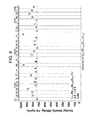
- FIGS. 1 and 2 illustrate powder X-ray diffraction patterns of a compound according to embodiments of the invention.
- FIGS. 3A and 3B illustrate the results of constant current charge and discharge cycles comparing a compound according to embodiments of the invention to a conventional OLS compound.
- FIG. 4 illustrates the results of cycle-life testing comparing a compound according to embodiments of the invention to a conventional OLS compound.
- FIG. 5 illustrates X-ray diffraction patterns from various compounds, including a compound according to embodiments of the invention.
- FIG. 6 illustrates the results of energy density measurements comparing doped compounds according to embodiments of the invention to a control compound. Multiple data points indicate multiple measurements.
- FIG. 7 illustrates the results of first cycle capacity measurements comparing doped compounds according to embodiments of the invention to a control compound. Multiple data points indicate multiple measurements.
- FIG. 8 illustrates the results of capacity retention (1 C over C/50 rate) measurements comparing doped compounds according to embodiments of the invention to a control compound. Multiple data points indicate multiple measurements.
- FIG. 9 illustrates the results of 1 C rate capacity measurements comparing doped compounds according to embodiments of the invention to a control compound. Multiple data points indicate multiple measurements.
- FIG. 10 illustrates the results of constant current charge and discharge cycles comparing doped compounds according to embodiments of the invention to a control compound.
- FIG. 11 illustrates the results of constant current charge and discharge cycles comparing doped compounds according to embodiments of the invention to a control compound.
- FIG. 12 illustrates the results of constant current charge and discharge cycles comparing doped compounds according to embodiments of the invention to a control compound.
- FIG. 13 illustrates the results of constant current charge and discharge cycles comparing doped compounds according to embodiments of the invention to a control compound.
- transition metal refers to a chemical element in groups 3 through 12 of the periodic table, including scandium (Sc), titanium (Ti), vanadium (V), chromium (Cr), manganese (Mn), iron (Fe), cobalt (Co), nickel (Ni), copper (Cu), zinc (Zn), yttrium (Y), zirconium (Zr), niobium (Nb), molybdenum (Mo), technetium (Tc), ruthenium (Ru), rhodium (Rh), palladium (Pd), silver (Ag), cadmium (Cd), hafnium (Hf), tantalum (Ta), tungsten (W), rhenium (Re), osmium (Os), iridium (Ir), platinum (Pt), gold (Au), mercury (Hg), rutherfordium (Rf), dubnium (Db), seaborgium (Sg), bohrium (Bh), hassium (H
- halogen refers to any of the elements in group 17 of the periodic table, including fluorine (F), chlorine (Cl), bromine (Br), iodine (I), and astatine (At).
- lanthanide refers to any of the fifteen metallic chemical elements with atomic numbers 57 through 71, including lanthanum (La), cerium (Ce), praseodymium (Pr), neodymium (Nd), promethium (Pm), samarium (Sm), europium (Eu), gadolinium (Gd), terbium (Tb), dysprosium (Dy), holmium (Ho), erbium (Er), thulium (Tm), ytterbium (Yb), and lutetium (Lu).
- La lanthanum
- Ce cerium
- Pr praseodymium
- Nd neodymium
- Pm promethium
- Sm samarium
- Eu europium
- Gd gadolinium
- Tb terbium
- Dy dysprosium
- Ho holmium
- Er erbium
- Tm thulium
- Yb yt
- alkali metal refers to any of the chemical elements in group 1 of the periodic table, including lithium (Li), sodium (Na), potassium (K), rubidium (Rb), cesium (Cs), and francium (Fr).
- alkaline earth metals refers to any of the chemical elements in group 2 of the periodic table, including beryllium (Be), magnesium (Mg), calcium (Ca), strontium (Sr), barium (Ba), and radium (Ra).
- OLS refers to over-lithiated spinel materials prepared according to methods known in the prior art, including, but not limited to, wet chemical methods such as those disclosed by Tarascon and co-workers (J. Electrochem. Soc., 138 (1991) 2864) demonstrating that Li 2 Mn 2 O 4 can be synthesized by a wet chemical method using acetonitrile and lithium iodide and Amine et. al. (J. Electrochem. Soc., 143 (1996) 1607) showing that Li 2 Mn 2 O 4 can be synthesized using a wet chemical method (a sol-gel method) also using acetonitrile and lithium iodide.
- CM3 refers to materials including at least lithium, manganese, nickel, and oxygen and being characterized by a powder X-ray diffraction pattern substantially the same as X-ray powder diffraction pattern in FIG. 1 or 2 , as well as functionally or structurally equivalent materials.
- specific capacity refers to the amount (e.g., total or maximum amount) of electrons or lithium ions a material is able to hold (or discharge) per unit mass and can be expressed in units of mAh/g.
- specific capacity can be measured in a constant current discharge (or charge) analysis, which includes discharge (or charge) at a defined rate over a defined voltage range against a defined counterelectrode.
- specific capacity can be measured upon discharge at a rate of about 0.05 C (e.g., about 14 mA/g) from 4.95 V to 2.0 V versus a Li/Li+ counterelectrode.
- discharge rates and other voltage ranges also can be used, such as a rate of about 0.1 C (e.g., about 28 mA/g), or about 0.5 C (e.g., about 140 mA/g), or about 1.0 C (e.g., about 280 mA/g).
- a rate “C” refers to either (depending on context) the discharge current as a fraction or multiple relative to a “1 C” current value under which a battery (in a substantially fully charged state) would substantially fully discharge in one hour, or the charge current as a fraction or multiple relative to a “1 C” current value under which the battery (in a substantially fully discharged state) would substantially fully charge in one hour.
- Ranges presented herein are inclusive of their endpoints.
- the range 1 to 3 includes the values 1 and 3 as well as the intermediate values.
- Embodiments of the present invention provide novel materials for use as active materials in cathodes of an electrochemical cell.
- the materials of the present invention address the challenges described above for existing cathode active materials.
- FIG. 2 depicts the X-ray diffraction patterns for a CM3 material (as measured using Cu K ⁇ radiation) for a wider range of 2 ⁇ angles while FIG. 1 is a view of the lower 2 ⁇ angle range.
- the peaks in a powder X-ray diffraction pattern correspond to a characteristic dimension between planes in a crystal structure.
- a slight shift in the position of a peak can mean that a characteristic dimension, such as a lattice parameter in a crystalline form, has shortened or lengthened.
- a slight shift can alternately signify that the crystalline form has changed morphology and different planes have emerged that give rise to a lattice parameter that is coincidentally slightly shifted from the original position of the peak.
- the x-ray diffraction patterns identify a particular crystalline structure for a compound.
- FIGS. 3A and 3B illustrate testing of a novel compound using the testing protocols described in the examples below compared to the known OLS material.
- FIG. 3A demonstrates improved performance by a CM3 compound as compared to conventional OLS materials.
- the CM3 compound demonstrates a higher voltage at the same capacity for many parts of the voltage traces.
- the CM3 compound stays above the critical moisture stability limit of 2.8 V for more of the trace than the OLS material.
- FIG. 3B demonstrates similar performance at voltages near 2.8 V. That is, in both FIGS. 3A and 3B , the CM3 compound has higher capacity and the trace for the CM3 compound does not have the same “plateau” shape seen in the trace for the OLS compound around 2.8 V.
- FIGS. 3A and 3B the voltage ranged from about 2.0 V to about 4.95 V.
- the rate was C/20.
- FIG. 3A confirms improved properties for the CM3 compound.
- the CM3 compound demonstrates a characteristic voltage profile that is distinct from that of the conventional OLS material.
- the 1st cycle coulombic efficiency was calculated during this testing and it was observed to be improved for the CM3 compound as compared to the conventional OLS material: the CM3 compound had a coulombic efficiency of 94.2% as compared to a coulombic efficiency of 83.8% for the OLS material.
- FIG. 4 illustrates testing according to protocols described in the examples below.
- a CM3 compound according to certain embodiments was tested and compared to a known OLS material.
- FIG. 3 demonstrates significant improvement in the specific capacity, the rate capability, and the cycle life of the CM3 compound.
- the voltage ranged from about 2.0 V to about 4.95 V.
- the cycling rate was C/5 for cycles 5 to 100 and the cycling rate was slower for cycles 1 to 4 and cycle 101.
- CM3 compounds of certain embodiments of the invention can demonstrate an energy density of approximately 950 Wh/Kg, which is comparable to next generation cathode materials such as lithium-rich layered oxides.
- the CM3 compound demonstrated initial specific capacity of greater than 200 mAh/g as measured by discharging a cell at less than 5 mA/g from 4.95 V to 2.5 V (vs. a Li/Li + anode).
- CM3 compounds according to embodiments of the invention demonstrate improved electrochemical properties as compared to known OLS materials, such as specific capacity, the rate capability, and cycle life. In these ways, CM3 compounds of embodiments of the invention address certain challenges that limit the widespread use of known OLS materials.
- OLS materials for use in certain embodiments can be prepared following synthetic routes generally represented by the following formulas (i) and (ii), although it is understood that these formulas are non-limiting and other equivalent synthetic routes for producing conventional OLS materials may be used.
- Formula (i) depicts the mixing of a stochiometric amount of three components where the components are first milled together. Mn 2 O 3 +Li 2 CO 3 +Ni(OH) 2 ⁇ LiMn 1.5 Ni 0.5 O 4 (i)
- the milled powder is then annealed to obtain the reaction product of formula (i).
- the annealing can take place, for example, at 700 degrees C. for 12 hours under air flow.
- the reaction product of formula (i) is a spinel material.
- the reaction product of formula (i) can then be over-lithiated by, for example, a wet chemical process to yield the reaction product of formula (ii). LiMn 1.5 Ni 0.5 O 4 ⁇ Li 2 Mn 1.5 Ni 0.5 O 4 (ii)
- the spinel material is heated in the presence of acetonitrile with lithium iodide as the lithium source. Heating can take place, for example, at 85 degrees C. to obtain the over-lithiated reaction product of formula (ii).
- the reaction product of formula (ii) is an over-lithiated spinel material, or OLS.
- a structurally-distinct lithium rich phase can be prepared according to formula (iii), where the reaction takes place by heating an over-lithiated spinel material for about 5 hours at 300 degrees C. under nitrogen gas: Li 2 Mn 1.5 Ni 0.5 O 4 ⁇ Li x Mn 1.5 ⁇ a Ni 0.5 ⁇ b O 4 ⁇ w (iii) where 1.6 ⁇ x ⁇ 2.2; 0 ⁇ a ⁇ 1.5; 0 ⁇ b ⁇ 0.5; and ⁇ 2 ⁇ w ⁇ 2.
- the reaction takes place by heating under an inert gas.
- an inert gas oxygen content changes during the heating process and therefore w is typically non-zero.
- the CM3 compound can be formed by heating an OLS material at a temperature greater than about 250 degrees C., greater than about 260 degrees C., greater than about 270 degrees C., greater than about 280 degrees C., greater than about 290 degrees C., greater than about 300 degrees C., greater than about 310 degrees C., greater than about 320 degrees C., greater than about 330 degrees C., or greater than about 340 degrees C.
- the novel compound can be formed by heating an OLS material at a temperature less than about 350 degrees C., less than about 340 degrees C., less than about 330 degrees C., less than about 320 degrees C., less than about 310 degrees C., less than about 300 degrees C., less than about 290 degrees C., less than about 280 degrees C., less than about 270 degrees C., or less than about 260 degrees C.
- the novel compounds can be formed by heating an OLS material at a temperature in a range from about 250 degrees C. to about 350 degrees C., from about 260 degrees C. to about 350 degrees C., from about 270 degrees C. to about 350 degrees C., from about 280 degrees C. to about 350 degrees C., from about 290 degrees C. to about 350 degrees C., or from about 300 degrees C. to about 350 degrees C.
- the novel compound can be formed by heating an OLS material for a time greater than about 0.5 hour, greater than about 1.0 hour, greater than about 1.5 hours, greater than about 2.5 hours, greater than about 3.0 hours, greater than about 3.5 hours, greater than about 4.0 hours, greater than about 4.5 hours, greater than about 5.0 hours, greater than about 5.5 hours, greater than about 6.0 hours, greater than about 6.5 hours, greater than about 7.0 hours, greater than about 7.5 hours, greater than about 8.0 hours, greater than about 8.5 hours, greater than about 9.0 hours, greater than about 9.5 hours, or greater than about 10.0 hours.
- the novel compound can be formed by heating an OLS material for a time less than about 0.5 hour, less than about 1.0 hour, less than about 1.5 hours, less than about 2.5 hours, less than about 3.0 hours, less than about 3.5 hours, less than about 4.0 hours, less than about 4.5 hours, less than about 5.0 hours, less than about 5.5 hours, less than about 6.0 hours, less than about 6.5 hours, less than about 7.0 hours, less than about 7.5 hours, less than about 8.0 hours, less than about 8.5 hours, less than about 9.0 hours, less than about 9.5 hours, or less than about 10.0 hours.
- the novel compounds can be formed by heating an OLS material for a time in a range from about 0.5 hour to about 10 hours, about 1 hour to about 9.5 hours, about 1.5 hours to about 9 hours, about 2.0 hours to about 8.5 hours, about 2.5 hours to about 8.0 hours, about 3.0 hours to about 7.5 hours, about 3.5 hours to about 7.0 hours, about 4.0 hours to about 6.5 hours, about 4.5 hours to about 6.0 hours, or about 5.0 hours to about 5.5 hours.
- FIG. 5 illustrates X-ray diffraction patterns from various compounds, including a CM3 compound according to embodiments of the invention.
- the CM3 compound has certain peaks that coincide with the peaks of the OLS material and certain peaks that have shifted as compared to the OLS material.
- the shifted peaks indicate that the CM3 compound is structurally distinct from the OLS material.
- the peak present in the X-ray diffraction pattern of the OLS material at about 34.7 degrees 2 ⁇ is shifted in the CM3 compound to about 35 degrees 2 ⁇ .
- the peak present in the X-ray diffraction pattern of the OLS material at about 41.4 degrees 2 ⁇ is shifted in the CM3 compound to about 42.1 degrees 2 ⁇ .
- the peak present in the X-ray diffraction pattern of the OLS material at about 44.6 degrees 2 ⁇ is shifted in the CM3 compound to about 44.5 degrees 2 ⁇ .
- the relative intensities of certain peaks are different in the CM3 compound as compared to the OLS material. Table 1 below lists certain peaks and their relative intensities. Of course, relative intensities can vary for a given material for reasons including morphology.
- peak present in the X-ray diffraction pattern of the OLS material are also present and unshifted in the OLS that has been heated for about 5 hours at 250 degrees C. under nitrogen gas. From comparison of these X-ray diffraction patterns it can be concluded that the OLS material is stable and relatively unchanged after being heated for about 5 hours at 250 degrees C. under nitrogen gas.
- Certain characteristically shifted peaks of the CM3 compound are not shifted in the X-ray diffraction pattern of the OLS material heated at 350 degrees C.
- the peaks in the X-ray diffraction pattern of the CM3 compound at about 35 degrees 2 ⁇ and at about 42.2 degrees 2 ⁇ appear to be missing from the X-ray diffraction pattern of the OLS material heated at 350 degrees C. for 5 hours.
- the peak in the X-ray diffraction pattern of the CM3 compound at about 44.3 degrees 2 ⁇ appears to be shifted back in the OLS material heated at 350 degrees C. for 5 hours to be aligned with the peak at about 44.5 degrees 2 ⁇ that is present in the OLS material.
- FIG. 5 demonstrates the synthesis of a novel compound that forms during a heat treatment at about 300 degrees C. and decomposes to a spinel structure at about 350 degrees C.
- This novel compound has a structure not previously seen for similar type of material. While the novel compound in this example was prepared by heat treatment of an OLS material, other synthetic routes for forming the novel compound are within the scope of this disclosure. For example, milling methods or other chemical, electrochemical, or physical processing routes (or combinations thereof) may yield the CM3 material and these routes are within the scope of this disclosure.
- doped spinel starting materials show improved electrochemical performance after undergoing the processing steps described herein.
- the dopant can be a transition metal, a lanthanide, an alkali metal, an alkaline earth metal, aluminum (Al), silicon (Si), bismuth (Bi), indium (In), lead (Pb), or combinations thereof.
- Doping Site Li Ca, Cu, Na, Sb, Sn, Ta, Ti Mn Al, Ba, Bi, Cr, Ge, Hf, Mo, Sn, Y Ni Cu, Hf, Mg, Ta O F, P
- FIGS. 6 through 9 illustrate the effects of the processing method on the properties of these materials as compared to the CM3 material.
- the dopant amounts (or “a+b” in formula (II)) were typically 0.01, 0.02, 0.05, or 0.1, but other doping amounts are within the scope of this disclosure.
- FIG. 6 illustrates the effect on energy density for various doped materials that were processed under the conditions described herein.
- doped materials of certain embodiments were heated for about 5 hours at 300 degrees C. under nitrogen gas.
- a heat-treated OLS material comprising Ta doped into the Ni site where d 0.05 demonstrated a significant improvement in energy density of about 18% over a CM3 material.
- FIG. 6 demonstrates energy improvement observed for different dopants on all four doping sites.
- FIG. 7 illustrates the effect on capacity for various doped OLS materials that were processed under the conditions described herein.
- doped OLS materials of certain embodiments were heated for about 5 hours at 300 degrees C. under nitrogen gas.
- a heat-treated OLS material comprising Ta doped into the Ni site where d 0.05 demonstrated a significant improvement in capacity of about 15% over a CM3 material.
- a heat-treated OLS material comprising F doped into the O site where d 0.05 demonstrated a significant improvement in capacity of about 10% over a CM3 material.
- FIG. 7 demonstrates capacity improvement observed for different dopants on all four doping sites.
- FIG. 8 illustrates the effect on capacity retention (1 C over 0.05 C) for various doped OLS materials that were processed under the conditions described herein.
- doped starting materials of certain embodiments were heated for about 5 hours at 300 degrees C. under nitrogen gas.
- FIG. 8 demonstrates capacity retention improvement at a 1 C rate observed for different dopants on all four doping sites.
- FIG. 9 illustrates the effect on capacity at 1 C rate for various doped OLS materials that were processed under the conditions described herein.
- doped OLS materials of certain embodiments were heated for about 5 hours at 300 degrees C. under nitrogen gas.
- a heat-treated OLS material comprising Ta doped into the Ni site where d 0.05 demonstrated a significant improvement in capacity at 1 C rate of about 15% over a CM3 material.
- FIG. 9 demonstrates rate capability improvement observed for different dopants on multiple doping sites.
- FIG. 10 illustrates voltage vs. capacity traces for charge and discharge cycles for certain doped OLS materials as compared to CM3 materials.
- FIG. 11 illustrates voltage vs. capacity traces for charge and discharge cycles for certain doped OLS materials as compared to CM3 materials.
- FIG. 12 illustrates voltage vs. capacity traces for charge and discharge cycles for a certain doped OLS material as compared to CM3 materials.
- FIG. 13 illustrates voltage vs. capacity traces for charge and discharge cycles for certain doped OLS materials as compared to CM3 materials.
- Doped spinel materials were synthesized by milling and annealing processes. Typically, stoichiometric amount of precursors (Mn 2 O 3 , Li 2 CO 3 , Ni(OH) 2 and others) were milled and the milled powder was annealed at 700 degrees C. for 12 hours under air flow (20 L/min) to obtain the doped spinel material. The amount of precursor was calculated based on the stoichiometry of the precursor and the final doped material. Stoichiometric amount of precursors were weighed and mixed together. After heating, the material was ground with a mortar and pestle before making the slurry. The resulting doped material was chemically over-lithiated and then heat-treated according to the synthesis described above.
- precursors Mn 2 O 3 , Li 2 CO 3 , Ni(OH) 2 and others
- Battery cells were formed in a high purity argon-filled glove box (M-Braun, O 2 and humidity content ⁇ 0.1 ppm).
- the electrodes were prepared by the following method: In case of a cathode, a novel compound was mixed with poly(vinylidene fluoride) (Sigma Aldrich), carbon black (Super P Li, TIMCAL), using 1-methyl-2-pyrrolidinone (Sigma Aldrich) as solvent, and the resulting slurry was deposited on a current collector and dried to form a composite cathode film. In case of an anode, a thin Li foil is cut into the required size and used as anode.
- Each battery cell including the composite cathode film, a polypropylene separator, and lithium foil anode, was assembled in a CR2032 coin cell (Hohsen). A conventional electrolyte mixed with an additive was used. The battery cell was sealed and cycled between about 2 V to about 4.95 V at 30° C. Batteries having electrodes made from doped, heat treated materials were tested in a voltage range from about 2.5 V to about 4.95 V.
Landscapes
- Chemical & Material Sciences (AREA)
- Inorganic Chemistry (AREA)
- Organic Chemistry (AREA)
- Chemical Kinetics & Catalysis (AREA)
- Electrochemistry (AREA)
- General Chemical & Material Sciences (AREA)
- Battery Electrode And Active Subsutance (AREA)
Priority Applications (1)
| Application Number | Priority Date | Filing Date | Title |
|---|---|---|---|
| US14/176,704 US9123959B2 (en) | 2013-02-11 | 2014-02-10 | High energy cathode material |
Applications Claiming Priority (2)
| Application Number | Priority Date | Filing Date | Title |
|---|---|---|---|
| US201361763195P | 2013-02-11 | 2013-02-11 | |
| US14/176,704 US9123959B2 (en) | 2013-02-11 | 2014-02-10 | High energy cathode material |
Publications (2)
| Publication Number | Publication Date |
|---|---|
| US20140225029A1 US20140225029A1 (en) | 2014-08-14 |
| US9123959B2 true US9123959B2 (en) | 2015-09-01 |
Family
ID=51296856
Family Applications (1)
| Application Number | Title | Priority Date | Filing Date |
|---|---|---|---|
| US14/176,704 Active US9123959B2 (en) | 2013-02-11 | 2014-02-10 | High energy cathode material |
Country Status (2)
| Country | Link |
|---|---|
| US (1) | US9123959B2 (fr) |
| WO (1) | WO2014124366A1 (fr) |
Cited By (2)
| Publication number | Priority date | Publication date | Assignee | Title |
|---|---|---|---|---|
| CN115136354A (zh) * | 2020-02-28 | 2022-09-30 | 松下知识产权经营株式会社 | 非水电解质二次电池用正极活性物质和非水电解质二次电池 |
| EP4112558A4 (fr) * | 2020-02-28 | 2023-08-30 | Panasonic Intellectual Property Management Co., Ltd. | Matériau actif d'électrode positive pour batterie secondaire à électrolyte non aqueux et batterie secondaire à électrolyte non aqueux |
Families Citing this family (6)
| Publication number | Priority date | Publication date | Assignee | Title |
|---|---|---|---|---|
| WO2016140352A1 (fr) | 2015-03-04 | 2016-09-09 | 日揮触媒化成株式会社 | Substance active d'électrode positive pour pile rechargeable à électrolyte non aqueux, électrode positive et pile rechargeable à électrolyte non aqueux |
| US10280092B2 (en) * | 2016-07-28 | 2019-05-07 | Wildcat Discovery Technologies, Inc | Oxides for high energy cathode materials |
| JP2018113130A (ja) * | 2017-01-10 | 2018-07-19 | 日揮触媒化成株式会社 | マンガン酸リチウム、該マンガン酸リチウムを含む正極、及び該正極を備える非水電解質二次電池 |
| CN108565445B (zh) * | 2018-06-04 | 2020-08-14 | 天津巴莫科技有限责任公司 | 一种高性能包覆型正极材料及其制备方法 |
| CN110451571A (zh) * | 2019-09-11 | 2019-11-15 | 杨杭福 | 一种具有反常磁热效应的钙钛矿锰氧化物及其制备方法 |
| CN111029560A (zh) * | 2019-12-03 | 2020-04-17 | 松山湖材料实验室 | 钠离子梯度掺杂的尖晶石结构正极活性材料及其制备方法 |
Citations (3)
| Publication number | Priority date | Publication date | Assignee | Title |
|---|---|---|---|---|
| US5738957A (en) | 1995-04-26 | 1998-04-14 | Japan Storage Battery Co., Ltd. | Positive electrode active material for lithium battery |
| JPH10208730A (ja) | 1997-01-24 | 1998-08-07 | Japan Storage Battery Co Ltd | 非水電解質二次電池 |
| JP2011243349A (ja) | 2010-05-17 | 2011-12-01 | Sanyo Electric Co Ltd | 正極活物質及びこの正極活物質を用いた非水電解質二次電池 |
-
2014
- 2014-02-10 WO PCT/US2014/015577 patent/WO2014124366A1/fr not_active Ceased
- 2014-02-10 US US14/176,704 patent/US9123959B2/en active Active
Patent Citations (3)
| Publication number | Priority date | Publication date | Assignee | Title |
|---|---|---|---|---|
| US5738957A (en) | 1995-04-26 | 1998-04-14 | Japan Storage Battery Co., Ltd. | Positive electrode active material for lithium battery |
| JPH10208730A (ja) | 1997-01-24 | 1998-08-07 | Japan Storage Battery Co Ltd | 非水電解質二次電池 |
| JP2011243349A (ja) | 2010-05-17 | 2011-12-01 | Sanyo Electric Co Ltd | 正極活物質及びこの正極活物質を用いた非水電解質二次電池 |
Non-Patent Citations (4)
| Title |
|---|
| Amine, "A New Three Volt Spinel Li1+Mn1.5Ni0.5O4 for Secondary Lithium Batteries," J. Electrochem Soc., vol. 143, No. 5, May 1996. |
| International Search Report and Written Opinion of PCT/US2014/015577 issued May 26, 2014. |
| Kim, "Composite 'Layered-Layered-Spinel' Cathode Structures for Lithium-Ion Batteries," Journal of the Electrochemical Society, 160 (1) A31-A38 (2013). |
| Wu et al. "Effects of heteroatoms on electrochemical performance of electrode materials for lithium ion batteries" Electrochemica Acta, 47 (2002) 3491-3507. * |
Cited By (3)
| Publication number | Priority date | Publication date | Assignee | Title |
|---|---|---|---|---|
| CN115136354A (zh) * | 2020-02-28 | 2022-09-30 | 松下知识产权经营株式会社 | 非水电解质二次电池用正极活性物质和非水电解质二次电池 |
| EP4113664A4 (fr) * | 2020-02-28 | 2023-08-30 | Panasonic Intellectual Property Management Co., Ltd. | Matériau actif d'électrode positive pour une batterie rechargeable à électrolyte non aqueux et batterie rechargeable à électrolyte non aqueux |
| EP4112558A4 (fr) * | 2020-02-28 | 2023-08-30 | Panasonic Intellectual Property Management Co., Ltd. | Matériau actif d'électrode positive pour batterie secondaire à électrolyte non aqueux et batterie secondaire à électrolyte non aqueux |
Also Published As
| Publication number | Publication date |
|---|---|
| US20140225029A1 (en) | 2014-08-14 |
| WO2014124366A1 (fr) | 2014-08-14 |
Similar Documents
| Publication | Publication Date | Title |
|---|---|---|
| US9123959B2 (en) | High energy cathode material | |
| US8535832B2 (en) | Metal oxide coated positive electrode materials for lithium-based batteries | |
| US7678503B2 (en) | Surface and bulk modified high capacity layered oxide cathodes with low irreversible capacity loss | |
| KR20200046749A (ko) | 복합양극활물질, 이를 포함한 양극, 리튬전지 및 그 제조 방법 | |
| JP2019029343A (ja) | 正極活物質、および、電池 | |
| TW201339098A (zh) | 具有所欲之電池效能之混合相鋰金屬氧化物組合物 | |
| KR20140066052A (ko) | 양극 활물질, 이의 제조방법 및 이를 포함하는 리튬 이차 전지 | |
| US20140162126A1 (en) | Cathode active material, method for preparing the same, and lithium secondary batteries including the same | |
| US10115962B2 (en) | High capacity cathode material with stabilizing nanocoatings | |
| KR20230034556A (ko) | 리튬 이차 전지용 양극 활물질, 이의 제조방법 및 이를 포함하는 리튬 이차 전지 | |
| US12206101B2 (en) | Disordered rock salt electrodes for lithium batteries | |
| JP2019029344A (ja) | 正極活物質、および、電池 | |
| KR20220089242A (ko) | 양극 활물질 및 이를 포함하는 리튬 이차 전지 | |
| US20170104212A1 (en) | Compositions for High Energy Electrodes and Methods of Making and Use | |
| KR20260049516A (ko) | 복합 코팅층을 포함하고 있는 양극 활물질 | |
| US20150372302A1 (en) | High energy cathode materials and methods of making and use | |
| US20170047587A1 (en) | Stabilized electrodes for lithium batteries | |
| US20190252671A1 (en) | Silicon (Si) Modified Li2MnO3-LiMO2 (M=Ni, Mn, Co) Cathode Material For Lithium-Ion Batteries | |
| CN116111066A (zh) | 正极材料及其制备方法、筛选高循环性能正极材料的方法、钠离子电池 | |
| US20150318546A1 (en) | Cobalt-stabilized lithium metal oxide electrodes for lithium batteries | |
| JP2022504835A (ja) | リチウム遷移金属複合酸化物およびその製造方法 | |
| CN119698700A (zh) | 二次电池用正极活性物质和二次电池 | |
| JP6190411B2 (ja) | 金属抽出によって作製した材料 | |
| JP2003346797A (ja) | ニッケルリチウム複合酸化物を用いた非水電解質二次電池 | |
| WO2024135669A1 (fr) | Matériau actif d'électrode positive pour batteries secondaires, et batterie secondaire |
Legal Events
| Date | Code | Title | Description |
|---|---|---|---|
| AS | Assignment |
Owner name: WILDCAT DISCOVERY TECHNOLOGIES, INC., CALIFORNIA Free format text: ASSIGNMENT OF ASSIGNORS INTEREST;ASSIGNORS:LI, BIN;CALDWELL, MARISSA;TONG, WEI;AND OTHERS;SIGNING DATES FROM 20140705 TO 20140723;REEL/FRAME:033408/0611 |
|
| STCF | Information on status: patent grant |
Free format text: PATENTED CASE |
|
| CC | Certificate of correction | ||
| AS | Assignment |
Owner name: SILICON VALLEY BANK, CALIFORNIA Free format text: SECURITY INTEREST;ASSIGNOR:WILDCAT DISCOVERY TECHNOLOGIES, INC.;REEL/FRAME:041255/0427 Effective date: 20160926 |
|
| MAFP | Maintenance fee payment |
Free format text: PAYMENT OF MAINTENANCE FEE, 4TH YR, SMALL ENTITY (ORIGINAL EVENT CODE: M2551); ENTITY STATUS OF PATENT OWNER: SMALL ENTITY Year of fee payment: 4 |
|
| AS | Assignment |
Owner name: WILDCAT DISCOVERY TECHNOLOGIES, INC., CALIFORNIA Free format text: RELEASE BY SECURED PARTY;ASSIGNOR:SILICON VALLEY BANK;REEL/FRAME:060063/0733 Effective date: 20220512 |
|
| MAFP | Maintenance fee payment |
Free format text: PAYMENT OF MAINTENANCE FEE, 8TH YR, SMALL ENTITY (ORIGINAL EVENT CODE: M2552); ENTITY STATUS OF PATENT OWNER: SMALL ENTITY Year of fee payment: 8 |
|
| AS | Assignment |
Owner name: UNITED STATES DEPARTMENT OF ENERGY, DISTRICT OF COLUMBIA Free format text: CONFIRMATORY LICENSE;ASSIGNOR:WILDCAT DISCOVERY TECHNOLOGIES, INC.;REEL/FRAME:068894/0005 Effective date: 20240822 |
|
| AS | Assignment |
Owner name: HSBC VENTURES USA INC., NEW YORK Free format text: SECURITY INTEREST;ASSIGNOR:WILDCAT DISCOVERY TECHNOLOGIES;REEL/FRAME:074128/0374 Effective date: 20251229 |