US9154012B2 - Fluid dynamic bearing device and assembly method for same - Google Patents
Fluid dynamic bearing device and assembly method for same Download PDFInfo
- Publication number
- US9154012B2 US9154012B2 US13/580,091 US201113580091A US9154012B2 US 9154012 B2 US9154012 B2 US 9154012B2 US 201113580091 A US201113580091 A US 201113580091A US 9154012 B2 US9154012 B2 US 9154012B2
- Authority
- US
- United States
- Prior art keywords
- outer member
- thrust bearing
- radial
- inner member
- peripheral surface
- Prior art date
- Legal status (The legal status is an assumption and is not a legal conclusion. Google has not performed a legal analysis and makes no representation as to the accuracy of the status listed.)
- Expired - Fee Related, expires
Links
- 239000012530 fluid Substances 0.000 title claims abstract description 191
- 238000000034 method Methods 0.000 title claims abstract description 79
- 239000002184 metal Substances 0.000 claims abstract description 126
- 229910052751 metal Inorganic materials 0.000 claims abstract description 126
- 238000003825 pressing Methods 0.000 claims abstract description 31
- 230000008569 process Effects 0.000 claims abstract description 31
- 230000002093 peripheral effect Effects 0.000 claims description 230
- 239000010687 lubricating oil Substances 0.000 claims description 85
- 239000011148 porous material Substances 0.000 claims description 28
- 238000009472 formulation Methods 0.000 claims description 12
- 239000000203 mixture Substances 0.000 claims description 12
- RYGMFSIKBFXOCR-UHFFFAOYSA-N Copper Chemical compound [Cu] RYGMFSIKBFXOCR-UHFFFAOYSA-N 0.000 claims description 11
- 229910052802 copper Inorganic materials 0.000 claims description 11
- 239000010949 copper Substances 0.000 claims description 11
- IYRDVAUFQZOLSB-UHFFFAOYSA-N copper iron Chemical compound [Fe].[Cu] IYRDVAUFQZOLSB-UHFFFAOYSA-N 0.000 claims description 10
- 230000004323 axial length Effects 0.000 claims description 5
- 229920005989 resin Polymers 0.000 description 67
- 239000011347 resin Substances 0.000 description 67
- 238000000465 moulding Methods 0.000 description 34
- 239000000853 adhesive Substances 0.000 description 28
- 230000001070 adhesive effect Effects 0.000 description 28
- 239000000463 material Substances 0.000 description 28
- 239000003921 oil Substances 0.000 description 27
- 230000004048 modification Effects 0.000 description 23
- 238000012986 modification Methods 0.000 description 23
- 238000005096 rolling process Methods 0.000 description 18
- 230000009471 action Effects 0.000 description 16
- 238000001746 injection moulding Methods 0.000 description 13
- 239000004033 plastic Substances 0.000 description 13
- XEEYBQQBJWHFJM-UHFFFAOYSA-N Iron Chemical compound [Fe] XEEYBQQBJWHFJM-UHFFFAOYSA-N 0.000 description 8
- 238000002347 injection Methods 0.000 description 8
- 239000007924 injection Substances 0.000 description 8
- 230000036316 preload Effects 0.000 description 6
- 230000009467 reduction Effects 0.000 description 6
- 230000008961 swelling Effects 0.000 description 6
- 238000005299 abrasion Methods 0.000 description 5
- 230000007246 mechanism Effects 0.000 description 5
- 229920006324 polyoxymethylene Polymers 0.000 description 5
- 238000007789 sealing Methods 0.000 description 5
- 238000004513 sizing Methods 0.000 description 5
- 230000003068 static effect Effects 0.000 description 5
- 238000009423 ventilation Methods 0.000 description 5
- 229920000106 Liquid crystal polymer Polymers 0.000 description 4
- 239000004977 Liquid-crystal polymers (LCPs) Substances 0.000 description 4
- 229910052742 iron Inorganic materials 0.000 description 4
- 238000004519 manufacturing process Methods 0.000 description 4
- 229930182556 Polyacetal Natural products 0.000 description 3
- 238000007906 compression Methods 0.000 description 3
- 230000006835 compression Effects 0.000 description 3
- 238000001816 cooling Methods 0.000 description 3
- 230000007423 decrease Effects 0.000 description 3
- 230000002542 deteriorative effect Effects 0.000 description 3
- 238000010438 heat treatment Methods 0.000 description 3
- 238000004381 surface treatment Methods 0.000 description 3
- 239000004952 Polyamide Substances 0.000 description 2
- 239000004734 Polyphenylene sulfide Substances 0.000 description 2
- 229910000831 Steel Inorganic materials 0.000 description 2
- 230000008901 benefit Effects 0.000 description 2
- 239000003795 chemical substances by application Substances 0.000 description 2
- 238000005097 cold rolling Methods 0.000 description 2
- 238000004891 communication Methods 0.000 description 2
- 230000001010 compromised effect Effects 0.000 description 2
- 230000008878 coupling Effects 0.000 description 2
- 238000010168 coupling process Methods 0.000 description 2
- 238000005859 coupling reaction Methods 0.000 description 2
- 239000000945 filler Substances 0.000 description 2
- 229920002647 polyamide Polymers 0.000 description 2
- 229920000069 polyphenylene sulfide Polymers 0.000 description 2
- 239000000843 powder Substances 0.000 description 2
- 230000002940 repellent Effects 0.000 description 2
- 239000005871 repellent Substances 0.000 description 2
- 229910001220 stainless steel Inorganic materials 0.000 description 2
- 239000010935 stainless steel Substances 0.000 description 2
- 239000010959 steel Substances 0.000 description 2
- 230000003245 working effect Effects 0.000 description 2
- 239000004593 Epoxy Substances 0.000 description 1
- 231100000597 Sick building syndrome Toxicity 0.000 description 1
- 239000004566 building material Substances 0.000 description 1
- 239000012141 concentrate Substances 0.000 description 1
- 239000004020 conductor Substances 0.000 description 1
- 230000003247 decreasing effect Effects 0.000 description 1
- 230000006866 deterioration Effects 0.000 description 1
- 230000000694 effects Effects 0.000 description 1
- 238000004540 process dynamic Methods 0.000 description 1
- 238000004080 punching Methods 0.000 description 1
- 239000012779 reinforcing material Substances 0.000 description 1
- 208000008842 sick building syndrome Diseases 0.000 description 1
- 239000000243 solution Substances 0.000 description 1
Images




Classifications
-
- H—ELECTRICITY
- H02—GENERATION; CONVERSION OR DISTRIBUTION OF ELECTRIC POWER
- H02K—DYNAMO-ELECTRIC MACHINES
- H02K5/00—Casings; Enclosures; Supports
- H02K5/04—Casings or enclosures characterised by the shape, form or construction thereof
- H02K5/16—Means for supporting bearings, e.g. insulating supports or means for fitting bearings in the bearing-shields
- H02K5/167—Means for supporting bearings, e.g. insulating supports or means for fitting bearings in the bearing-shields using sliding-contact or spherical cap bearings
- H02K5/1672—Means for supporting bearings, e.g. insulating supports or means for fitting bearings in the bearing-shields using sliding-contact or spherical cap bearings radially supporting the rotary shaft at both ends of the rotor
-
- F—MECHANICAL ENGINEERING; LIGHTING; HEATING; WEAPONS; BLASTING
- F16—ENGINEERING ELEMENTS AND UNITS; GENERAL MEASURES FOR PRODUCING AND MAINTAINING EFFECTIVE FUNCTIONING OF MACHINES OR INSTALLATIONS; THERMAL INSULATION IN GENERAL
- F16C—SHAFTS; FLEXIBLE SHAFTS; ELEMENTS OR CRANKSHAFT MECHANISMS; ROTARY BODIES OTHER THAN GEARING ELEMENTS; BEARINGS
- F16C17/00—Sliding-contact bearings for exclusively rotary movement
- F16C17/10—Sliding-contact bearings for exclusively rotary movement for both radial and axial load
- F16C17/102—Sliding-contact bearings for exclusively rotary movement for both radial and axial load with grooves in the bearing surface to generate hydrodynamic pressure
- F16C17/107—Sliding-contact bearings for exclusively rotary movement for both radial and axial load with grooves in the bearing surface to generate hydrodynamic pressure with at least one surface for radial load and at least one surface for axial load
-
- F—MECHANICAL ENGINEERING; LIGHTING; HEATING; WEAPONS; BLASTING
- F16—ENGINEERING ELEMENTS AND UNITS; GENERAL MEASURES FOR PRODUCING AND MAINTAINING EFFECTIVE FUNCTIONING OF MACHINES OR INSTALLATIONS; THERMAL INSULATION IN GENERAL
- F16C—SHAFTS; FLEXIBLE SHAFTS; ELEMENTS OR CRANKSHAFT MECHANISMS; ROTARY BODIES OTHER THAN GEARING ELEMENTS; BEARINGS
- F16C33/00—Parts of bearings; Special methods for making bearings or parts thereof
- F16C33/02—Parts of sliding-contact bearings
- F16C33/04—Brasses; Bushes; Linings
- F16C33/06—Sliding surface mainly made of metal
- F16C33/10—Construction relative to lubrication
- F16C33/1025—Construction relative to lubrication with liquid, e.g. oil, as lubricant
- F16C33/106—Details of distribution or circulation inside the bearings, e.g. details of the bearing surfaces to affect flow or pressure of the liquid
- F16C33/107—Grooves for generating pressure
-
- F—MECHANICAL ENGINEERING; LIGHTING; HEATING; WEAPONS; BLASTING
- F16—ENGINEERING ELEMENTS AND UNITS; GENERAL MEASURES FOR PRODUCING AND MAINTAINING EFFECTIVE FUNCTIONING OF MACHINES OR INSTALLATIONS; THERMAL INSULATION IN GENERAL
- F16C—SHAFTS; FLEXIBLE SHAFTS; ELEMENTS OR CRANKSHAFT MECHANISMS; ROTARY BODIES OTHER THAN GEARING ELEMENTS; BEARINGS
- F16C33/00—Parts of bearings; Special methods for making bearings or parts thereof
- F16C33/02—Parts of sliding-contact bearings
- F16C33/04—Brasses; Bushes; Linings
- F16C33/06—Sliding surface mainly made of metal
- F16C33/12—Structural composition; Use of special materials or surface treatments, e.g. for rust-proofing
- F16C33/128—Porous bearings, e.g. bushes of sintered alloy
-
- F—MECHANICAL ENGINEERING; LIGHTING; HEATING; WEAPONS; BLASTING
- F16—ENGINEERING ELEMENTS AND UNITS; GENERAL MEASURES FOR PRODUCING AND MAINTAINING EFFECTIVE FUNCTIONING OF MACHINES OR INSTALLATIONS; THERMAL INSULATION IN GENERAL
- F16C—SHAFTS; FLEXIBLE SHAFTS; ELEMENTS OR CRANKSHAFT MECHANISMS; ROTARY BODIES OTHER THAN GEARING ELEMENTS; BEARINGS
- F16C33/00—Parts of bearings; Special methods for making bearings or parts thereof
- F16C33/02—Parts of sliding-contact bearings
- F16C33/04—Brasses; Bushes; Linings
- F16C33/06—Sliding surface mainly made of metal
- F16C33/14—Special methods of manufacture; Running-in
-
- F—MECHANICAL ENGINEERING; LIGHTING; HEATING; WEAPONS; BLASTING
- F16—ENGINEERING ELEMENTS AND UNITS; GENERAL MEASURES FOR PRODUCING AND MAINTAINING EFFECTIVE FUNCTIONING OF MACHINES OR INSTALLATIONS; THERMAL INSULATION IN GENERAL
- F16C—SHAFTS; FLEXIBLE SHAFTS; ELEMENTS OR CRANKSHAFT MECHANISMS; ROTARY BODIES OTHER THAN GEARING ELEMENTS; BEARINGS
- F16C43/00—Assembling bearings
- F16C43/02—Assembling sliding-contact bearings
-
- F—MECHANICAL ENGINEERING; LIGHTING; HEATING; WEAPONS; BLASTING
- F16—ENGINEERING ELEMENTS AND UNITS; GENERAL MEASURES FOR PRODUCING AND MAINTAINING EFFECTIVE FUNCTIONING OF MACHINES OR INSTALLATIONS; THERMAL INSULATION IN GENERAL
- F16C—SHAFTS; FLEXIBLE SHAFTS; ELEMENTS OR CRANKSHAFT MECHANISMS; ROTARY BODIES OTHER THAN GEARING ELEMENTS; BEARINGS
- F16C2220/00—Shaping
- F16C2220/02—Shaping by casting
- F16C2220/04—Shaping by casting by injection-moulding
-
- F—MECHANICAL ENGINEERING; LIGHTING; HEATING; WEAPONS; BLASTING
- F16—ENGINEERING ELEMENTS AND UNITS; GENERAL MEASURES FOR PRODUCING AND MAINTAINING EFFECTIVE FUNCTIONING OF MACHINES OR INSTALLATIONS; THERMAL INSULATION IN GENERAL
- F16C—SHAFTS; FLEXIBLE SHAFTS; ELEMENTS OR CRANKSHAFT MECHANISMS; ROTARY BODIES OTHER THAN GEARING ELEMENTS; BEARINGS
- F16C2220/00—Shaping
- F16C2220/20—Shaping by sintering pulverised material, e.g. powder metallurgy
-
- F—MECHANICAL ENGINEERING; LIGHTING; HEATING; WEAPONS; BLASTING
- F16—ENGINEERING ELEMENTS AND UNITS; GENERAL MEASURES FOR PRODUCING AND MAINTAINING EFFECTIVE FUNCTIONING OF MACHINES OR INSTALLATIONS; THERMAL INSULATION IN GENERAL
- F16C—SHAFTS; FLEXIBLE SHAFTS; ELEMENTS OR CRANKSHAFT MECHANISMS; ROTARY BODIES OTHER THAN GEARING ELEMENTS; BEARINGS
- F16C2226/00—Joining parts; Fastening; Assembling or mounting parts
- F16C2226/10—Force connections, e.g. clamping
- F16C2226/12—Force connections, e.g. clamping by press-fit, e.g. plug-in
-
- F—MECHANICAL ENGINEERING; LIGHTING; HEATING; WEAPONS; BLASTING
- F16—ENGINEERING ELEMENTS AND UNITS; GENERAL MEASURES FOR PRODUCING AND MAINTAINING EFFECTIVE FUNCTIONING OF MACHINES OR INSTALLATIONS; THERMAL INSULATION IN GENERAL
- F16C—SHAFTS; FLEXIBLE SHAFTS; ELEMENTS OR CRANKSHAFT MECHANISMS; ROTARY BODIES OTHER THAN GEARING ELEMENTS; BEARINGS
- F16C2226/00—Joining parts; Fastening; Assembling or mounting parts
- F16C2226/10—Force connections, e.g. clamping
- F16C2226/14—Force connections, e.g. clamping by shrink fit, i.e. heating and shrinking part to allow assembly
-
- F—MECHANICAL ENGINEERING; LIGHTING; HEATING; WEAPONS; BLASTING
- F16—ENGINEERING ELEMENTS AND UNITS; GENERAL MEASURES FOR PRODUCING AND MAINTAINING EFFECTIVE FUNCTIONING OF MACHINES OR INSTALLATIONS; THERMAL INSULATION IN GENERAL
- F16C—SHAFTS; FLEXIBLE SHAFTS; ELEMENTS OR CRANKSHAFT MECHANISMS; ROTARY BODIES OTHER THAN GEARING ELEMENTS; BEARINGS
- F16C2226/00—Joining parts; Fastening; Assembling or mounting parts
- F16C2226/30—Material joints
- F16C2226/40—Material joints with adhesive
-
- F—MECHANICAL ENGINEERING; LIGHTING; HEATING; WEAPONS; BLASTING
- F16—ENGINEERING ELEMENTS AND UNITS; GENERAL MEASURES FOR PRODUCING AND MAINTAINING EFFECTIVE FUNCTIONING OF MACHINES OR INSTALLATIONS; THERMAL INSULATION IN GENERAL
- F16C—SHAFTS; FLEXIBLE SHAFTS; ELEMENTS OR CRANKSHAFT MECHANISMS; ROTARY BODIES OTHER THAN GEARING ELEMENTS; BEARINGS
- F16C2360/00—Engines or pumps
- F16C2360/46—Fans, e.g. ventilators
-
- H—ELECTRICITY
- H02—GENERATION; CONVERSION OR DISTRIBUTION OF ELECTRIC POWER
- H02K—DYNAMO-ELECTRIC MACHINES
- H02K2205/00—Specific aspects not provided for in the other groups of this subclass relating to casings, enclosures, supports
- H02K2205/03—Machines characterised by thrust bearings
-
- H—ELECTRICITY
- H02—GENERATION; CONVERSION OR DISTRIBUTION OF ELECTRIC POWER
- H02K—DYNAMO-ELECTRIC MACHINES
- H02K2213/00—Specific aspects, not otherwise provided for and not covered by codes H02K2201/00 - H02K2211/00
- H02K2213/09—Machines characterised by the presence of elements which are subject to variation, e.g. adjustable bearings, reconfigurable windings, variable pitch ventilators
Definitions
- the fluid dynamic bearing device described in Patent Literature 2 includes: an outer member (first bearing member) including a first bearing ring ( 12 ), and a pair of first bearing plates ( 16 and 20 ) projecting toward an inner diameter side from the first bearing ring ( 12 ); and an inner member (second bearing member) including a cylindrical second bearing ring ( 14 ) to be mounted to a rotary shaft, and a second bearing plate ( 18 ) fixed to an outer peripheral surface of the second bearing ring ( 14 ).
- Dynamic pressure generating grooves are formed in the radial bearing surface of the inner member made of a sintered metal, or dynamic pressure generating grooves are formed in each of the radial bearing surface and the thrust bearing surfaces of the inner member.
- the outer member comprises two members including a first outer member and a second outer member.
- the first outer member has a substantially L-shape in vertical cross-section, and comprises a cylindrical portion and a radial portion provided along one axial end of the cylindrical portion.
- the radial bearing surface is formed on an inner peripheral surface of the cylindrical portion, and the one of the thrust bearing surfaces is formed on an inside surface of the radial portion.
- the second outer member has a disk-like shape and an inside surface on which the another of the thrust bearing surfaces is formed.
- An outer peripheral surface of the second outer member having the disk-like shape is fitted to the inner peripheral surface of the cylindrical portion of the first outer member.
- Another invention of the present application provides an assembly method for a fluid dynamic bearing device, the fluid dynamic bearing device comprising: an outer member having a radial bearing surface and thrust bearing surfaces respectively formed on both axial sides of the radial bearing surface; and an inner member arranged on an inner diameter side with respect to the outer member and having a radial bearing surface and thrust bearing surfaces respectively facing the radial bearing surface of the outer member and the thrust bearing surfaces of the outer member, the radial bearing surface of the outer member and the radial bearing surface of the inner member forming a radial bearing gap therebetween, one of the thrust bearing surfaces of the outer member and one of the thrust bearing surfaces of the inner member forming one thrust bearing gap therebetween, another of the thrust bearing surfaces of the outer member and another of the thrust bearing surfaces of the inner member forming another thrust bearing gap therebetween, the outer member comprising two members including a first outer member and a second outer member, the thrust bearing surfaces of the outer member being formed respectively on an inside surface of the first outer member and an inside surface of the second outer member, the assembly method
- the bringing the one of the thrust bearing surfaces of the projecting portion of the inner member into abutment against the thrust bearing surface of the first outer member comprises: setting the first outer member on a placing surface of a first jig having the placing surface and a bottom surface; inserting the projecting portion of the inner member into the first outer member so that the projecting portion of the inner member abuts against the thrust bearing surface of the first outer member; press-fitting, after the inserting, the sleeve portion to the projecting portion until an end surface of the sleeve portion abuts against the bottom surface of the first jig; setting, after the press-fitting, a set of the first outer member and the inner member on a placing surface of a second jig, the second jig having the placing surface and a bottom surface different from the placing surface and the bottom surface of the first jig; and bringing the end surface of the sleeve portion into abutment against the bottom surface of the second jig so
- an assembly method comprising, in the following order: arranging the inner member on an inner periphery of the inside outer member; temporarily fixing the outside outer member and the inside outer member under a state in which the thrust bearing gaps are set by fitting the inner peripheral surface of the outside outer member and the outer peripheral surface of the inside outer member to each other and by press-fitting the projection portion provided to one of the inner peripheral surface of the outside outer member and the outer peripheral surface of the inside outer member to another of the inner peripheral surface of the outside outer member and the outer peripheral surface of the inside outer member; and injecting and curing an adhesive between the inner peripheral surface of the outside outer member and the outer peripheral surface of the inside outer member.
- An exhaust fan motor comprises: the fluid dynamic bearing device according to the present invention, which comprises a plurality of fluid dynamic bearing devices arranged apart from each other in the axial direction; and a motor rotor arranged between the fluid dynamic bearing devices adjacent to each other.
- the outer member when the outer member is formed by injection molding with use of the inner member as an insert component, the outer member can be molded together with the pair of shoulder surfaces. Simultaneously, the inner member can be assembled to the outer member between the pair of shoulder surfaces in the axial direction. Therefore, the number of components and assembly man-hours can be reduced.
- molding shrinkage can be generated in a direction in which the shoulder surface 23 of the outer member 20 is moved axially outward with corresponding one of both the axial end surfaces M 2 of the core metal M as a reference.
- the shrinkage occurs in a direction in which the resin concentrates on both axial end portions (dotted line portion) of the core metal M.
- the core metal in the outer member is made of a sintered metal
- dimensional accuracy of the core metal can be enhanced.
- the core metal faces the radial bearing gap
- the lubricating oil impregnated in inner pores of the core metal made of a sintered metal can be supplied into the radial bearing gap.
- lubricity can be enhanced.
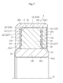
- FIG. 6 A vertical sectional view of a fluid dynamic bearing device according to a modification of the first embodiment of the first invention of the present application.
- FIG. 12 b Another vertical sectional view illustrating the assembly method for the fluid dynamic bearing device according to the first embodiment of the first invention of the present application.
- FIG. 15 A vertical sectional view illustrating the assembly method for the fluid dynamic bearing device according to the second embodiment of the first invention of the present application.
- FIG. 16 A horizontal sectional view illustrating a state in which an adhesive is injected into a fitting portion of the inner member and an outer member of the fluid dynamic bearing device according to the second embodiment of the first invention of the present application.
- FIG. 17 b A horizontal sectional view of a fitting portion of the inner member and the outer member of the fluid dynamic bearing device according to a modification of the second embodiment of the first invention of the present application.
- FIG. 23 A front view of indicators for identifying a rotational direction.
- FIG. 25 A vertical sectional view of a fluid dynamic bearing device according to a second embodiment of the second invention of the present application.
- FIG. 34 A sectional view of the bearing unit (when the motor is stopped).
- FIG. 37 A side view of the inner member.
- FIG. 17 are each a horizontal sectional view of a structure in which the first outer member 20 a and the second outer member 20 b are fitted to and temporarily fixed to each other.
- a plurality of protruding portions 21 a are provided on the inner peripheral surface 21 of the cylindrical portion 20 a 1 of the first outer member 20 a .
- Those protruding portions 21 a are press-fitted to an outer peripheral surface 40 of the cylindrical portion 20 b 1 of the second outer member 20 b . With this, press-fitting can be performed without deterioration of accuracies of the first outer member 20 a and the second outer member 20 b .
- FIG. 18 is an axial sectional view of a bearing unit 1 incorporating a fluid dynamic bearing device according to a first embodiment of the second invention of the present application.
- the bearing unit 1 is used, for example, by being incorporated into a motor for a small exhaust fan for a 24-hour ventilation system to be installed in a dwelling room of a house (more strictly speaking, inner-rotor motor for an exhaust fan).
- FIG. 23 illustrates the identification grooves 44 in detail.
- FIG. 23 is a right side view of the fluid dynamic bearing device 4 , illustrating the entire side surface comprising a lower half with respect to the axial line H of the fluid dynamic bearing device 4 .
- An inside outer member 20 b is fitted to an outside outer member 20 a , and a fitting portion thereof is fixed by bonding.
- the end surface 43 of the sleeve portion 10 b of the inner member 10 is provided with the identification grooves 44 .
- the identification grooves 44 are formed at two points on a diameter, and those identifications groove 44 are formed by a powder molding step or a sizing step for the inner member 10 made of a sintered metal.
- an inner peripheral surface 29 of a cylindrical portion 20 b 1 of the inside outer member 20 b forms a radial bearing surface 29 R.
- An inside surface 22 of the radial portion 20 a 2 of the outside outer member 20 a and an inside surface 23 of the radial portion 20 b 2 of the inside outer member 20 b respectively form thrust bearing surface 22 T and 23 T.
- the inner peripheral surface 29 and the inside surfaces 22 and 23 are each formed of an even and smooth surface, and the dynamic pressure generating grooves 11 a , 12 a , and 13 a are formed respectively in the outer peripheral surface 11 and both the side surfaces 12 and 13 of the projecting portion 10 a of the inner member 10 .
- the spring 7 urges the outer member 20 of the fluid dynamic bearing device 4 on the left side of FIG. 18 into a right direction of FIG. 18 .
- the outer member 20 urged by the spring 7 is held in abutment against the inner member 10 , and hence the inner member 10 and the rotary shaft 2 are urged to the right direction of FIG. 18 .
- the inner member 10 of the right fluid dynamic bearing device 4 of FIG. 18 is urged to the right direction of FIG. 18 , with the result of being held in abutment against and engaged with the outer member.
- the housing 5 and the spring 7 apply a preload in a direction in which the pair of fluid dynamic bearing devices 4 and 4 comes close to each other.
- the dynamic pressure generating grooves 22 a and 23 a in both the thrust directions are formed, for example, by a pressing process when the outside outer member 20 a and the inside outer member 20 b are formed of a plate member by a pressing.
- the dynamic pressure generating grooves 22 a and 23 a also can be formed with high accuracy.
- Shapes of the dynamic pressure generating grooves 22 a and 23 a are the same as those illustrated in FIGS. 20( a ) and 20 ( c ).
- the inner member 10 is made of a sintered metal.
- the projection portion 27 a and indicators for identification of the rotational direction are the same as those in the first embodiment.
- a jig used in this assembly method is formed of a fixing jig F and a moving jig G which is arranged inside of the fixing jig F and movable in a vertical direction.
- the fixing jig F has a placing surface 30 , a guide surface 34 , and an inner peripheral surface 35 fitted to the moving jig G in a freely slidable manner.
- the moving jig G has a shoulder surface 36 , a guide surface 37 , and an outer peripheral surface 38 fitted to the fixing jig F in a freely slidable manner. In the state illustrated in FIG. 28 , the moving jig G is retracted downward.
- the pair of shoulder surfaces 23 and 23 is formed in the resin molded portion N, and each have a shape symmetrical with each other with respect to the axial center plane.
- the shoulder surface 23 is formed of a tapered surface 23 a provided on the outer diameter side and a flat surface 23 b provided on the inner diameter side.
- the tapered surface 23 a is provided while being inclined toward the outer diameter side and an axial central portion side (that is, side on which the shoulder surfaces 23 and 23 come close to each other).
- the flat surface 23 b extends from an inner diameter end of the tapered surface 23 a toward the inner diameter side.
- the spring 7 applies an axial preload to both the fluid dynamic bearing devices 4 and 4 .
- the elastic force of the spring 7 is set within such a range that the outer member 20 is prevented from being rotated and the outer member 20 and the inner member 10 are prevented from coming into sliding contact with each other.
- the elastic force of the spring 7 be set approximately to range from 20% to 80% of a load capacity of the pressure generated in the thrust bearing gaps T.
Landscapes
- Engineering & Computer Science (AREA)
- General Engineering & Computer Science (AREA)
- Mechanical Engineering (AREA)
- Physics & Mathematics (AREA)
- Fluid Mechanics (AREA)
- Power Engineering (AREA)
- Chemical & Material Sciences (AREA)
- Oil, Petroleum & Natural Gas (AREA)
- Metallurgy (AREA)
- Sliding-Contact Bearings (AREA)
- Mounting Of Bearings Or Others (AREA)
Applications Claiming Priority (7)
| Application Number | Priority Date | Filing Date | Title |
|---|---|---|---|
| JP2010074454A JP2011208670A (ja) | 2010-03-29 | 2010-03-29 | 流体動圧軸受装置及びその製造方法 |
| JP2010-074454 | 2010-03-29 | ||
| JP2010103394A JP5528897B2 (ja) | 2010-04-28 | 2010-04-28 | 流体動圧軸受装置およびその組み立て方法 |
| JP2010-103394 | 2010-04-28 | ||
| JP2010186055A JP2012042035A (ja) | 2010-08-23 | 2010-08-23 | 流体動圧軸受装置およびその組立方法 |
| JP2010-186055 | 2010-08-23 | ||
| PCT/JP2011/057631 WO2011122556A1 (ja) | 2010-03-29 | 2011-03-28 | 流体動圧軸受装置およびその組立方法 |
Publications (2)
| Publication Number | Publication Date |
|---|---|
| US20120315169A1 US20120315169A1 (en) | 2012-12-13 |
| US9154012B2 true US9154012B2 (en) | 2015-10-06 |
Family
ID=44712252
Family Applications (1)
| Application Number | Title | Priority Date | Filing Date |
|---|---|---|---|
| US13/580,091 Expired - Fee Related US9154012B2 (en) | 2010-03-29 | 2011-03-28 | Fluid dynamic bearing device and assembly method for same |
Country Status (4)
| Country | Link |
|---|---|
| US (1) | US9154012B2 (ja) |
| EP (1) | EP2554859B1 (ja) |
| CN (1) | CN102844576B (ja) |
| WO (1) | WO2011122556A1 (ja) |
Cited By (1)
| Publication number | Priority date | Publication date | Assignee | Title |
|---|---|---|---|---|
| US12247617B2 (en) | 2022-12-08 | 2025-03-11 | Hamilton Sundstrand Corporation | Cavitation resistant journal bearing |
Families Citing this family (11)
| Publication number | Priority date | Publication date | Assignee | Title |
|---|---|---|---|---|
| JP5335621B2 (ja) * | 2009-08-28 | 2013-11-06 | Ntn株式会社 | すべり軸受およびこれを備えるすべり軸受ユニット、並びにこの軸受ユニットを備えるモータ |
| JP6100046B2 (ja) * | 2013-03-19 | 2017-03-22 | Ntn株式会社 | 流体動圧軸受装置およびこれを備えるモータ |
| JP6189065B2 (ja) * | 2013-03-25 | 2017-08-30 | Ntn株式会社 | 流体動圧軸受装置およびその組立方法 |
| US10424988B2 (en) * | 2013-04-05 | 2019-09-24 | General Electric Company | Downhole electric submersible pumps with high rotordynamic stability margin |
| EP2803874B1 (en) * | 2013-05-13 | 2019-08-14 | Aktiebolaget SKF | Landing bearing and magnetic bearing assembly |
| EP2803875B1 (en) * | 2013-05-13 | 2019-03-13 | Aktiebolaget SKF | Landing bearing and magnetic bearing assembly |
| JP6502068B2 (ja) * | 2014-11-20 | 2019-04-17 | Ntn株式会社 | 流体動圧軸受装置の製造方法 |
| EP3104031B1 (en) * | 2015-06-10 | 2019-08-07 | MAHLE International GmbH | Sliding element comprising a flexible adhesive |
| DE102018220462A1 (de) * | 2018-11-28 | 2020-05-28 | Hanon Systems Efp Deutschland Gmbh | Elektrisch angetriebene Maschine, insbesondere Pumpe |
| TWI715450B (zh) * | 2020-02-25 | 2021-01-01 | 建準電機工業股份有限公司 | 軸承系統及其止推板 |
| CN112128246B (zh) * | 2020-09-22 | 2022-08-12 | 东南大学 | 一种轴向小孔常压供水动静压螺旋槽推力轴承 |
Citations (26)
| Publication number | Priority date | Publication date | Assignee | Title |
|---|---|---|---|---|
| JPH10311331A (ja) | 1997-05-09 | 1998-11-24 | Matsushita Seiko Co Ltd | スラスト軸受 |
| US5941646A (en) | 1996-12-25 | 1999-08-24 | Ntn Corporation | Hydrodynamic type porous oil-impregnated bearing and bearing device |
| JP2000249142A (ja) | 1999-03-03 | 2000-09-12 | Nsk Ltd | 転がり軸受 |
| JP2001132738A (ja) | 1999-11-02 | 2001-05-18 | Seiko Instruments Inc | フランジ付シャフトの組立方法、及び流体動圧軸受 |
| US6536983B1 (en) * | 2000-01-20 | 2003-03-25 | Engineered Controls International Inc. | Crimp joint for pressure containing gas and fluid distribution devices |
| US6554576B2 (en) * | 2000-05-22 | 2003-04-29 | Itt Richter Chemie-Technik Gmbh | Magnetically coupled and self-lubricated pump with bearing burnout protection |
| US20030091249A1 (en) | 2001-11-13 | 2003-05-15 | Tetsuya Kurimura | Fluid lubricated bearing device |
| JP2004108550A (ja) | 2002-09-20 | 2004-04-08 | Koyo Seiko Co Ltd | 動圧軸受装置 |
| US20040120619A1 (en) * | 2002-12-18 | 2004-06-24 | Dong-Yeh Chai | Independent rotational supportive pad with use of flat bearing ring plate for CRT/TFT-LCD/PDP television monitor, computer monitor, stereo speaker, laptop computers and dinner dishes |
| JP2004316926A (ja) * | 2004-07-28 | 2004-11-11 | Ntn Corp | 動圧型軸受ユニット及びその製造方法 |
| JP2004353871A (ja) | 1996-12-25 | 2004-12-16 | Ntn Corp | 動圧型多孔質含油軸受 |
| US20060120643A1 (en) | 2002-11-13 | 2006-06-08 | Tetsuya Kurimura | Fluid lubricated bearing device |
| JP2006189081A (ja) | 2005-01-05 | 2006-07-20 | Ntn Corp | 流体軸受装置 |
| JP2006342975A (ja) * | 2006-09-25 | 2006-12-21 | Ntn Corp | 動圧型軸受装置 |
| JP2007024089A (ja) | 2005-07-12 | 2007-02-01 | Ntn Corp | 動圧軸受装置およびモータ |
| JP2007051717A (ja) | 2005-08-18 | 2007-03-01 | Ntn Corp | 動圧軸受装置の製造方法 |
| JP2007162950A (ja) | 2001-11-13 | 2007-06-28 | Ntn Corp | 流体軸受装置 |
| US20070230843A1 (en) | 2006-01-06 | 2007-10-04 | Tetsuya Kurimura | Fluid lubricated bearing device |
| JP2008190711A (ja) | 2006-07-21 | 2008-08-21 | Ntn Corp | 動圧軸受装置の製造方法 |
| US20080267544A1 (en) | 2007-04-26 | 2008-10-30 | Martin Engesser | Fluid dynamic bearing system |
| JP2008267531A (ja) | 2007-04-23 | 2008-11-06 | Ntn Corp | 動圧軸受装置の製造方法 |
| JP2008298235A (ja) | 2007-06-01 | 2008-12-11 | Ntn Corp | 流体軸受装置及びその組み立て方法 |
| WO2009001960A1 (ja) | 2007-06-28 | 2008-12-31 | Nidec Corporation | 流体動圧軸受、この流体動圧軸受を備えたモータ、および、流体動圧軸受の製造方法 |
| US20090142010A1 (en) | 2005-01-05 | 2009-06-04 | Ntn Corporation | Sintered metal material, sintered oil-impregnated bearing formed of the metal material, and fluid lubrication bearing device |
| US20110097025A1 (en) * | 2008-07-08 | 2011-04-28 | Ntn Corporation | Fluid dynamic bearing device |
| US20120133226A1 (en) * | 2009-08-28 | 2012-05-31 | Ntn Corporation | Slide bearing, slide bearing unit with same, and motor with the bearing unit |
-
2011
- 2011-03-28 WO PCT/JP2011/057631 patent/WO2011122556A1/ja not_active Ceased
- 2011-03-28 EP EP11762780.2A patent/EP2554859B1/en not_active Not-in-force
- 2011-03-28 CN CN201180016768.2A patent/CN102844576B/zh not_active Expired - Fee Related
- 2011-03-28 US US13/580,091 patent/US9154012B2/en not_active Expired - Fee Related
Patent Citations (32)
| Publication number | Priority date | Publication date | Assignee | Title |
|---|---|---|---|---|
| US5941646A (en) | 1996-12-25 | 1999-08-24 | Ntn Corporation | Hydrodynamic type porous oil-impregnated bearing and bearing device |
| JP2004353871A (ja) | 1996-12-25 | 2004-12-16 | Ntn Corp | 動圧型多孔質含油軸受 |
| JPH10311331A (ja) | 1997-05-09 | 1998-11-24 | Matsushita Seiko Co Ltd | スラスト軸受 |
| JP2000249142A (ja) | 1999-03-03 | 2000-09-12 | Nsk Ltd | 転がり軸受 |
| JP2001132738A (ja) | 1999-11-02 | 2001-05-18 | Seiko Instruments Inc | フランジ付シャフトの組立方法、及び流体動圧軸受 |
| US6536983B1 (en) * | 2000-01-20 | 2003-03-25 | Engineered Controls International Inc. | Crimp joint for pressure containing gas and fluid distribution devices |
| US6554576B2 (en) * | 2000-05-22 | 2003-04-29 | Itt Richter Chemie-Technik Gmbh | Magnetically coupled and self-lubricated pump with bearing burnout protection |
| US20030091249A1 (en) | 2001-11-13 | 2003-05-15 | Tetsuya Kurimura | Fluid lubricated bearing device |
| US20080212906A1 (en) | 2001-11-13 | 2008-09-04 | Tetsuya Kurimura | Fluid lubricated bearing device |
| JP2007162950A (ja) | 2001-11-13 | 2007-06-28 | Ntn Corp | 流体軸受装置 |
| US20080187258A1 (en) | 2001-11-13 | 2008-08-07 | Tetsuya Kurimura | Fluid lubricated bearing device |
| US20080107368A1 (en) | 2001-11-13 | 2008-05-08 | Tetsuya Kurimura | Fluid lubricated bearing device |
| JP2004108550A (ja) | 2002-09-20 | 2004-04-08 | Koyo Seiko Co Ltd | 動圧軸受装置 |
| US20060120643A1 (en) | 2002-11-13 | 2006-06-08 | Tetsuya Kurimura | Fluid lubricated bearing device |
| US20040120619A1 (en) * | 2002-12-18 | 2004-06-24 | Dong-Yeh Chai | Independent rotational supportive pad with use of flat bearing ring plate for CRT/TFT-LCD/PDP television monitor, computer monitor, stereo speaker, laptop computers and dinner dishes |
| JP2004316926A (ja) * | 2004-07-28 | 2004-11-11 | Ntn Corp | 動圧型軸受ユニット及びその製造方法 |
| JP2006189081A (ja) | 2005-01-05 | 2006-07-20 | Ntn Corp | 流体軸受装置 |
| US20090142010A1 (en) | 2005-01-05 | 2009-06-04 | Ntn Corporation | Sintered metal material, sintered oil-impregnated bearing formed of the metal material, and fluid lubrication bearing device |
| JP2007024089A (ja) | 2005-07-12 | 2007-02-01 | Ntn Corp | 動圧軸受装置およびモータ |
| JP2007051717A (ja) | 2005-08-18 | 2007-03-01 | Ntn Corp | 動圧軸受装置の製造方法 |
| US20070230843A1 (en) | 2006-01-06 | 2007-10-04 | Tetsuya Kurimura | Fluid lubricated bearing device |
| JP2008190711A (ja) | 2006-07-21 | 2008-08-21 | Ntn Corp | 動圧軸受装置の製造方法 |
| JP2006342975A (ja) * | 2006-09-25 | 2006-12-21 | Ntn Corp | 動圧型軸受装置 |
| JP2008267531A (ja) | 2007-04-23 | 2008-11-06 | Ntn Corp | 動圧軸受装置の製造方法 |
| US20100132197A1 (en) | 2007-04-23 | 2010-06-03 | Ntn Corporation | Method for manufacturing fluid dynamic bearing device |
| JP2008275159A (ja) | 2007-04-26 | 2008-11-13 | Minebea Co Ltd | 流体動圧軸受装置 |
| US20080267544A1 (en) | 2007-04-26 | 2008-10-30 | Martin Engesser | Fluid dynamic bearing system |
| JP2008298235A (ja) | 2007-06-01 | 2008-12-11 | Ntn Corp | 流体軸受装置及びその組み立て方法 |
| WO2009001960A1 (ja) | 2007-06-28 | 2008-12-31 | Nidec Corporation | 流体動圧軸受、この流体動圧軸受を備えたモータ、および、流体動圧軸受の製造方法 |
| JP2009008160A (ja) | 2007-06-28 | 2009-01-15 | Nippon Densan Corp | 流体動圧軸受機構、流体動圧軸受機構の製造方法およびモータ |
| US20110097025A1 (en) * | 2008-07-08 | 2011-04-28 | Ntn Corporation | Fluid dynamic bearing device |
| US20120133226A1 (en) * | 2009-08-28 | 2012-05-31 | Ntn Corporation | Slide bearing, slide bearing unit with same, and motor with the bearing unit |
Non-Patent Citations (6)
| Title |
|---|
| International Search Report for PCT/JP2011/057631, mailing date of Jun. 28, 2011. |
| Machine Translation of JP 2004-353871. * |
| Machine translation of JP 2007-024089. * |
| Machine translation of JP 2007-051717. * |
| Machine Translation of JP H10-311331. * |
| Notification of Transmittal of Translation of the International Preliminary Report on Patentabililty (Form PCT/IB/338) of International Application No. PCT/JP2011/057631 mailed Nov. 1, 2012 with Forms PCT/IB/373 and PCT/ISA/237. |
Cited By (1)
| Publication number | Priority date | Publication date | Assignee | Title |
|---|---|---|---|---|
| US12247617B2 (en) | 2022-12-08 | 2025-03-11 | Hamilton Sundstrand Corporation | Cavitation resistant journal bearing |
Also Published As
| Publication number | Publication date |
|---|---|
| US20120315169A1 (en) | 2012-12-13 |
| EP2554859A4 (en) | 2014-03-19 |
| CN102844576A (zh) | 2012-12-26 |
| EP2554859B1 (en) | 2017-03-22 |
| CN102844576B (zh) | 2015-12-02 |
| WO2011122556A1 (ja) | 2011-10-06 |
| EP2554859A1 (en) | 2013-02-06 |
Similar Documents
| Publication | Publication Date | Title |
|---|---|---|
| US9154012B2 (en) | Fluid dynamic bearing device and assembly method for same | |
| US9127710B2 (en) | Slide bearing, slide bearing unit with same, and motor with the bearing unit | |
| CN101305193B (zh) | 树脂制保持器和滚动轴承 | |
| EP2899417B1 (en) | Fluid dynamic bearing device and motor with same | |
| US8317403B2 (en) | Rolling bearing with a split bearing ring | |
| JP2012505361A5 (ja) | ||
| JP2002369474A (ja) | インペラ軸支持用転がり軸受装置 | |
| JP2011196544A (ja) | 流体動圧軸受装置 | |
| JP5528897B2 (ja) | 流体動圧軸受装置およびその組み立て方法 | |
| CN107949710B (zh) | 推力滚子轴承和轴承装置 | |
| JP2012042035A (ja) | 流体動圧軸受装置およびその組立方法 | |
| JP2011127713A (ja) | 玉軸受用保持器およびこれを備える玉軸受 | |
| US10054156B2 (en) | Synthetic resin retainer for large thrust ball bearings with dry-lubricant and wet-lubricant management systems | |
| JPH0932856A (ja) | 滑り軸受及びその製造方法 | |
| JP6668098B2 (ja) | 流体動圧軸受装置 | |
| US20120062079A1 (en) | Rotor for Motor | |
| JP6087066B2 (ja) | 流体動圧軸受装置、及び、流体動圧軸受装置の製造方法 | |
| JP2011208670A (ja) | 流体動圧軸受装置及びその製造方法 | |
| JP5832849B2 (ja) | 流体動圧軸受装置およびその製造方法 | |
| CN218216923U (zh) | 用于电机的端盖以及电机 | |
| CN113819144A (zh) | 一种轴承保持架、滚动球轴承及电机 | |
| CN220488096U (zh) | 一种轴承组件 | |
| JP6261922B2 (ja) | 流体動圧軸受装置及び内方部材の製造方法 | |
| JP2012072816A (ja) | 流体動圧軸受装置およびその組立方法 | |
| US20240376931A1 (en) | Cage for rolling elements of high-speed bearing and high-speed bearing |
Legal Events
| Date | Code | Title | Description |
|---|---|---|---|
| AS | Assignment |
Owner name: NTN CORPORATION, JAPAN Free format text: ASSIGNMENT OF ASSIGNORS INTEREST;ASSIGNORS:HORI, MASAHARU;HIRADE, JUN;HAYASHI, TATSUYA;AND OTHERS;SIGNING DATES FROM 20120727 TO 20120802;REEL/FRAME:028821/0032 |
|
| STCF | Information on status: patent grant |
Free format text: PATENTED CASE |
|
| FEPP | Fee payment procedure |
Free format text: MAINTENANCE FEE REMINDER MAILED (ORIGINAL EVENT CODE: REM.); ENTITY STATUS OF PATENT OWNER: LARGE ENTITY |
|
| LAPS | Lapse for failure to pay maintenance fees |
Free format text: PATENT EXPIRED FOR FAILURE TO PAY MAINTENANCE FEES (ORIGINAL EVENT CODE: EXP.); ENTITY STATUS OF PATENT OWNER: LARGE ENTITY |
|
| STCH | Information on status: patent discontinuation |
Free format text: PATENT EXPIRED DUE TO NONPAYMENT OF MAINTENANCE FEES UNDER 37 CFR 1.362 |
|
| FP | Lapsed due to failure to pay maintenance fee |
Effective date: 20191006 |