US9232306B2 - Systems and methods for reducing stray magnetic flux - Google Patents
Systems and methods for reducing stray magnetic flux Download PDFInfo
- Publication number
- US9232306B2 US9232306B2 US13/833,636 US201313833636A US9232306B2 US 9232306 B2 US9232306 B2 US 9232306B2 US 201313833636 A US201313833636 A US 201313833636A US 9232306 B2 US9232306 B2 US 9232306B2
- Authority
- US
- United States
- Prior art keywords
- audio
- electronic device
- audio component
- component
- sensor
- Prior art date
- Legal status (The legal status is an assumption and is not a legal conclusion. Google has not performed a legal analysis and makes no representation as to the accuracy of the status listed.)
- Expired - Fee Related, expires
Links
Images


Classifications
-
- H—ELECTRICITY
- H04—ELECTRIC COMMUNICATION TECHNIQUE
- H04R—LOUDSPEAKERS, MICROPHONES, GRAMOPHONE PICK-UPS OR LIKE ACOUSTIC ELECTROMECHANICAL TRANSDUCERS; ELECTRIC HEARING AIDS; PUBLIC ADDRESS SYSTEMS
- H04R9/00—Transducers of moving-coil, moving-strip, or moving-wire type
- H04R9/02—Details
-
- H—ELECTRICITY
- H04—ELECTRIC COMMUNICATION TECHNIQUE
- H04R—LOUDSPEAKERS, MICROPHONES, GRAMOPHONE PICK-UPS OR LIKE ACOUSTIC ELECTROMECHANICAL TRANSDUCERS; ELECTRIC HEARING AIDS; PUBLIC ADDRESS SYSTEMS
- H04R3/00—Circuits for transducers
-
- H—ELECTRICITY
- H04—ELECTRIC COMMUNICATION TECHNIQUE
- H04R—LOUDSPEAKERS, MICROPHONES, GRAMOPHONE PICK-UPS OR LIKE ACOUSTIC ELECTROMECHANICAL TRANSDUCERS; ELECTRIC HEARING AIDS; PUBLIC ADDRESS SYSTEMS
- H04R31/00—Apparatus or processes specially adapted for the manufacture of transducers or diaphragms therefor
-
- H—ELECTRICITY
- H04—ELECTRIC COMMUNICATION TECHNIQUE
- H04R—LOUDSPEAKERS, MICROPHONES, GRAMOPHONE PICK-UPS OR LIKE ACOUSTIC ELECTROMECHANICAL TRANSDUCERS; ELECTRIC HEARING AIDS; PUBLIC ADDRESS SYSTEMS
- H04R5/00—Stereophonic arrangements
- H04R5/02—Spatial or constructional arrangements of loudspeakers
-
- H—ELECTRICITY
- H04—ELECTRIC COMMUNICATION TECHNIQUE
- H04R—LOUDSPEAKERS, MICROPHONES, GRAMOPHONE PICK-UPS OR LIKE ACOUSTIC ELECTROMECHANICAL TRANSDUCERS; ELECTRIC HEARING AIDS; PUBLIC ADDRESS SYSTEMS
- H04R9/00—Transducers of moving-coil, moving-strip, or moving-wire type
-
- H—ELECTRICITY
- H04—ELECTRIC COMMUNICATION TECHNIQUE
- H04R—LOUDSPEAKERS, MICROPHONES, GRAMOPHONE PICK-UPS OR LIKE ACOUSTIC ELECTROMECHANICAL TRANSDUCERS; ELECTRIC HEARING AIDS; PUBLIC ADDRESS SYSTEMS
- H04R2209/00—Details of transducers of the moving-coil, moving-strip, or moving-wire type covered by H04R9/00 but not provided for in any of its subgroups
- H04R2209/022—Aspects regarding the stray flux internal or external to the magnetic circuit, e.g. shielding, shape of magnetic circuit, flux compensation coils
-
- H—ELECTRICITY
- H04—ELECTRIC COMMUNICATION TECHNIQUE
- H04R—LOUDSPEAKERS, MICROPHONES, GRAMOPHONE PICK-UPS OR LIKE ACOUSTIC ELECTROMECHANICAL TRANSDUCERS; ELECTRIC HEARING AIDS; PUBLIC ADDRESS SYSTEMS
- H04R2499/00—Aspects covered by H04R or H04S not otherwise provided for in their subgroups
- H04R2499/10—General applications
- H04R2499/15—Transducers incorporated in visual displaying devices, e.g. televisions, computer displays, laptops
-
- Y—GENERAL TAGGING OF NEW TECHNOLOGICAL DEVELOPMENTS; GENERAL TAGGING OF CROSS-SECTIONAL TECHNOLOGIES SPANNING OVER SEVERAL SECTIONS OF THE IPC; TECHNICAL SUBJECTS COVERED BY FORMER USPC CROSS-REFERENCE ART COLLECTIONS [XRACs] AND DIGESTS
- Y10—TECHNICAL SUBJECTS COVERED BY FORMER USPC
- Y10T—TECHNICAL SUBJECTS COVERED BY FORMER US CLASSIFICATION
- Y10T29/00—Metal working
- Y10T29/49—Method of mechanical manufacture
- Y10T29/49002—Electrical device making
- Y10T29/49005—Acoustic transducer
Definitions
- This relates to systems and methods for reducing stray magnetic flux, and, more particularly, to systems and methods for reducing the effects of stray magnetic flux from a loudspeaker in an electronic device.
- stray magnetic flux that is potentially disruptive to adjacent magnetically sensitive device components (e.g., Hall sensors and hard drives). If stray flux is not adequately kept away from certain magnetically sensitive components, those components may fail and/or cause damage to the electronic device.
- a traditional way to reduce such stray magnetic flux interference is to provide a shield about the component generating the stray magnetic flux and/or about the component to be protected from the stray magnetic flux. However, such a shield often takes up valuable real estate within a device.
- an electronic device can include a first audio component configured to have a first acoustic phase and a first magnetic phase, and a second audio component configured to have the first acoustic phase and a second magnetic phase that is opposite the first magnetic phase.
- the first audio component can be positioned with respect to the second audio component such that stray magnetic flux from the first audio component enters the second audio component during operation of the first and second audio components. For example, the stray magnetic flux can be encouraged to enter the second audio component and complete its flux loop.
- a method of manufacturing an electronic device can include positioning a first audio component within the electronic device.
- the first audio component can be positioned to provide a first acoustic phase and a first magnetic phase.
- the method can also include situating a second audio component within the electronic device.
- the second audio component can be situated to provide the first acoustic phase and a second magnetic phase opposite the first magnetic phase.
- the first and second audio components can also be oriented relative to one another such that the first and second magnetic phases cause stray magnetic flux from the first audio component to enter the second audio component during operation of the first and second audio components. For example, the stray magnetic flux can be encouraged to enter the second audio component and complete its flux loop.
- FIG. 1 is a simplified schematic diagram of an electronic device, in accordance with at least one embodiment of the invention.
- FIG. 2 shows a top, front, right perspective view of the electronic device of FIG. 1 in an open position, in accordance with at least one embodiment of the invention
- FIG. 3 shows a bottom, back, left perspective view of the electronic device of FIGS. 1 and 2 in a closed position, in accordance with at least one embodiment of the invention
- FIG. 4 shows a partial cross-sectional view of a loudspeaker assembly, in accordance with at least one embodiment of the invention
- FIG. 5 shows a cross-sectional of a pair of adjacent magnet assemblies of corresponding loudspeakers, in accordance with at least one embodiment of the invention.
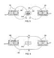
- FIG. 6 shows a cross-sectional view of a different pair of magnet assemblies of corresponding loudspeakers, in accordance with at least one embodiment of the invention.
- FIGS. 1-6 Systems and methods for reducing stray magnetic flux in an electronic device are provided and described with reference to FIGS. 1-6 .
- FIG. 1 is a simplified schematic diagram of an electronic device 100 that may be configured to reduce stray magnetic flux or leakage flux.
- Electronic device 100 may be any portable, mobile, or hand-held electronic device. Alternatively, electronic device 100 may not be portable, but may instead be generally stationary.
- Electronic device 100 can include, but is not limited to, a music player (e.g., an iPodTM available by Apple Inc.
- Electronic device 100 may include a processor or control circuitry 102 , memory 104 , communications circuitry 106 , power supply 108 , input component 110 , and output component 112 .
- Electronic device 100 may also include a bus 114 that may provide one or more wired or wireless communication links or paths for transferring data and/or power to, from, or between various other components of device 100 .
- one or more components of electronic device 100 may be combined or omitted.
- electronic device 100 may include other components not combined or included in FIG. 1 .
- electronic device 100 may also include a compass, positioning circuitry, and/or several instances of one or more of the components shown in FIG. 1 . For the sake of simplicity, only one of each of the components is shown in FIG. 1 .
- Memory 104 may include one or more storage mediums, including for example, a hard disk drive (“HDD”), flash memory, permanent memory such as read-only memory (“ROM”), semi-permanent memory such as random access memory (“RAM”), any other suitable type of storage component, or any combination thereof.
- Memory 104 may include cache memory, which may be one or more different types of memory used for temporarily storing data for electronic device applications.
- Memory 104 may store media data (e.g., music and image files), software (e.g., for implementing functions on device 100 ), firmware, preference information (e.g., media playback preferences), lifestyle information (e.g., food preferences), exercise information (e.g., information obtained by exercise monitoring equipment), transaction information (e.g., information such as credit card information), wireless connection information (e.g., information that may enable device 100 to establish a wireless connection), subscription information (e.g., information that keeps track of podcasts or television shows or other media a user subscribes to), contact information (e.g., telephone numbers and e-mail addresses), calendar information, any other suitable data, or any combination thereof.
- media data e.g., music and image files
- software e.g., for implementing functions on device 100
- firmware e.g., firmware
- preference information e.g., media playback preferences
- lifestyle information e.g., food preferences
- exercise information e.g., information obtained by exercise monitoring equipment
- Communications circuitry 106 may be provided to allow device 100 to communicate with one or more other electronic devices or servers using any suitable communications protocol.
- communications circuitry 106 may support Wi-Fi (e.g., an 802.11 protocol), Ethernet, BluetoothTM, high frequency systems (e.g., 900 MHz, 2.4 GHz, and 5.6 GHz communication systems), infrared, transmission control protocol/internet protocol (“TCP/IP”) (e.g., any of the protocols used in each of the TCP/IP layers), hypertext transfer protocol (“HTTP”), BitTorrentTM, file transfer protocol (“FTP”), real-time transport protocol (“RTP”), real-time streaming protocol (“RTSP”), secure shell protocol (“SSH”), any other communications protocol, or any combination thereof.
- Communications circuitry 106 may also include circuitry that can enable device 100 to be electrically coupled to another device (e.g., a host computer or an accessory device) and communicate with that other device, either wirelessly or via a wired connection.
- another device e.g., a host
- Power supply 108 may provide power to one or more of the components of device 100 .
- power supply 108 can be coupled to a power grid (e.g., when device 100 is not a portable device, such as a desktop computer).
- power supply 108 can include one or more batteries for providing power (e.g., when device 100 is a portable device, such as a cellular telephone).
- power supply 108 can be configured to generate power from a natural source (e.g., solar power using solar cells).
- One or more input components 110 may be provided to permit a user to interact or interface with device 100 .
- input component 110 can take a variety of forms, including, but not limited to, a touch pad, dial, click wheel, scroll wheel, touch screen, one or more buttons (e.g., a keyboard), mouse, joy stick, track ball, microphone, camera, proximity sensor, Hall effect sensor, light detector, motion sensor, and any combinations thereof.
- buttons e.g., a keyboard
- Each input component 110 can be configured to provide one or more dedicated control functions for making selections or issuing commands associated with operating device 100 .
- Electronic device 100 may also include one or more output components 112 that may present information (e.g., graphical, audible, and/or tactile information) to a user of device 100 .
- output component 112 can take a variety of forms, including, but not limited to, audio loudspeakers, headphones, signal lines-out, visual displays, antennas, infrared ports, rumblers, vibrators, and any combinations thereof.
- one or more input components 110 and one or more output components 112 may sometimes be referred to collectively herein as an input/output (“I/O”) component or I/O interface.
- I/O input/output
- input component 110 and output component 112 may sometimes be a single I/O component, such as a touch screen, that may receive input information through a user's touch of a display screen and that may also provide visual information to a user via that same display screen.
- Processor 102 of device 100 may include any processing circuitry operative to control the operations and performance of one or more components of electronic device 100 .
- processor 102 may be used to run operating system applications, firmware applications, graphics editing applications, media playback applications, media editing applications, or any other application.
- processor 102 may receive input signals from input component 110 and/or drive output signals through output component 112 .
- Processor 102 may load a user interface program (e.g., a program stored in memory 104 or another device or server accessible by device 100 ) to determine how instructions or data received via input component 110 may manipulate the way in which information is stored and/or provided to the user via output component 112 .
- a user interface program e.g., a program stored in memory 104 or another device or server accessible by device 100
- Electronic device 100 may also be provided with a housing 101 that may at least partially enclose one or more of the components of device 100 for protection from debris and other degrading forces external to device 100 .
- housing 101 may include several walls that can define a cavity within which the various electronic components of device 100 can be disposed.
- housing 101 can support various electronic components of device 100 , such as one or more input/output (“I/O”) components 110 and/or I/O components 112 , at the surfaces or within openings through the surfaces of the walls of housing 101 .
- I/O input/output
- housing 101 can be formed from a wide variety of materials including, but not limited to, metals (e.g., steel, copper, titanium, aluminum, and various metal alloys), ceramics, plastics, glass, and any combinations thereof. Housing 101 may also help to define the shape or form of electronic device 100 . That is, the contour of housing 101 may embody the outward physical appearance of electronic device 100 .
- Electronic device 100 is illustrated in FIGS. 2 and 3 to be a laptop computer, although it is to be understood that electronic device 100 may be any type of electronic device as described herein.
- housing 101 of electronic device 100 may be configured to provide two housing components coupled together by a hinge or clutch assembly.
- housing 101 may include a base housing component 101 a and a display housing component 101 b coupled to one another by a hinge assembly 101 c , which may also be known as clutch assembly 101 c .
- Housing components 101 a , 101 b , and 101 c may be configured such that electronic device 100 may be “opened” for use (see, e.g., FIG.
- housing 101 of device 100 is only exemplary and need not include two substantially hexahedral portions coupled by a hinge.
- the housing of device 100 could generally be formed in any other suitable shape, including, but not limited to, one or more housing components or portions that are substantially spherical, ellipsoidal, conoidal, octahedral, and any combinations thereof.
- Base housing component 101 a may include a top wall 121 , a bottom wall 126 opposite top wall 121 , and various side walls, such as front wall 122 , back wall 123 opposite front wall 122 , right wall 124 , and left wall 125 opposite right wall 124 .
- one or more openings may be provided through one or more of the walls of housing component 101 a to at least partially expose one or more components of electronic device 100 .
- at least one opening 131 may be provided through top wall 121 of base housing component 101 a to at least partially expose an input component 110 a of electronic device 100 .
- FIG. 2 at least one opening 131 may be provided through top wall 121 of base housing component 101 a to at least partially expose an input component 110 a of electronic device 100 .
- openings 141 a , 141 b , 141 c , and 141 d may be provided through top wall 121 of base housing component 101 a to at least partially expose respective output components 112 a , 112 b , 112 c , and 112 d of electronic device 100 .
- display housing component 101 b may include a top wall 161 , a bottom wall (not shown) opposite top wall 161 , and various side walls, such as front wall 162 , back wall 163 opposite front wall 162 , right wall 164 , and left wall 165 opposite right wall 164 .
- one or more openings may be provided through one or more of the walls of housing component 101 b to at least partially expose one or more components of electronic device 100 .
- an opening 151 may be provided through top wall 161 of display housing component 101 b to at least partially expose an output component 112 c of electronic device 100 .
- Input component 110 a is illustrated in FIG. 2 to be a keyboard, although it is to be understood that input component 110 a , which may be exposed by opening 131 through top wall 121 of housing component 101 a , may be any type of input component 110 as described herein.
- output components 112 a , 112 b , 112 c , and 112 d are illustrated in FIG. 2 to be audio loudspeakers, it is to be understood that each one of output components 112 a , 112 b , 112 c , and 112 d , which may be exposed by respective openings 141 a - 141 d through top wall 121 of housing component 101 a , may be any type of output component 112 as described herein.
- output component 112 c is illustrated in FIG. 2 to be a visual display, it is to be understood that output component 112 c , which may be exposed by opening 151 through top wall 161 of housing component 101 b , also may be any type of output component 112 as described herein.
- FIG. 4 shows a detailed cross-sectional view of an exemplary audio loudspeaker assembly 412 , which may be similar to one or more of audio loudspeakers 112 a , 112 b , 112 c , and 112 d of FIG. 2 .
- a magnetic air gap 477 may be formed between an under yoke 472 and a top plate 478 , using a permanent magnet 476 .
- Under yoke 472 , permanent magnet 476 , and top plate 478 may be collectively referred to herein as a magnet assembly 470 .
- An electrically conductive voice coil 482 may be wound about or otherwise coupled to a former 488 .
- Coil 482 can be wound such that current flows in a +X-direction (e.g., out of the page) in portions 481 of coil 482 , and flows in a ⁇ X-direction (e.g., into the page) in portions 483 of coil 482 .
- a frame 490 may be coupled to and may extend from magnet assembly 470 .
- a diaphragm or cone 492 may extend from a top portion 495 of frame 490 to a top portion of former 488 about axis A.
- Surround 494 may serve to suspend and maintain cone 492 and former 488 centered about and aligned with respect to top plate 478 , while also serving to allow axial movement along axis A of voice coil 482 and former 488 within magnetic air gap 477 of magnet assembly 470 .
- alternating current e.g., an audio electrical signal provided by an audio source of device 100 , such as an amplifier
- voice coil 482 e.g., as shown in FIG. 4
- coil 482 can be subjected to a force due to a stationary magnetic field in gap 477 .
- This is commonly referred to as the Lorentz force, and is the cross product of the stationary magnetic field in gap 477 and the current in coil 482 .
- This force can alternate sign (or direction), depending on the direction of current in coil 482 , and can displace cone 492 and surround 494 in the ⁇ Z-directions to generate sound waves.
- loudspeakers may be shown in cross-section herein (e.g., because speakers may generally be cylindrically or rotationally symmetrical about an axis line or center line, such as axis A of FIG. 4 ), one skilled in the art may appreciate the three-dimensional structure of such loudspeakers and that one or more of the loudspeakers described herein may not necessarily be axially symmetric.
- FIG. 4 shows an axially symmetric loudspeaker having a magnet assembly disposed interior to coil 482 , it should be appreciated that an axially symmetric loudspeaker can instead have a magnet assembly disposed exterior to coil 482 .
- a device can include two or more output components or loudspeakers positioned adjacent one another.
- the magnet assembly of each of these loudspeakers can be similarly oriented, and can provide the same magnetic phase.
- FIG. 5 shows a cross-sectional of a pair of magnet assemblies 570 and 571 of corresponding loudspeakers (not shown) that can each be similar to magnet assembly 470 .
- magnet assembly 570 can be oriented to provide a magnetic flux path 541
- magnet assembly 571 can be oriented to provide a similar magnetic flux path 542 in the same magnetic phase as magnetic flux path 541 .
- any magnetic flux that may stray from each flux path may form a self-closing flux loop with the respective magnet assembly.
- stray magnetic flux Gc may form a self-closing flux loop 543
- stray magnetic flux Gd may form a self-closing flux loop 544 .
- Flux loops 543 and 544 may interfere with any component positioned between magnet assemblies 570 and 571 that may have its own magnetic flux.
- a magnetically sensitive input device component 514 e may be positioned in between magnet assemblies 570 and 571 in the same X-Y plane.
- magnetically sensitive input component 514 e may be a Hall effect sensor or any other suitable input component that may be affected by stray magnetic flux of another component.
- magnetically sensitive input component 514 e may have its own magnetic flux sensitivity direction 539 extending therethrough (e.g., in the ⁇ Z direction).
- the additional magnetic flux that may be added to flux 539 of magnetically sensitive input component 514 e by stray fluxes Gc and Gd may adversely affect the performance of input component 514 e (e.g., by destructive or constructive superposition of the stray flux densities).
- a Hall Effect Sensor which may use a magnet to flip a switch, can be either tripped prematurely or held in the tripped state if there is leakage flux present.
- the two adjacent loudspeaker assemblies may be oriented in opposition magnetically. That is, a first loudspeaker assembly may be configured to be of the same acoustic phase as a proximal second loudspeaker assembly, but the first loudspeaker assembly may be configured to be of an opposite magnetic phase from the second loudspeaker assembly, such that the stray flux of each loudspeaker assembly may be guided into the magnetic flux of the other loudspeaker. This may redistribute flux away from any sensitive device disposed between the loudspeakers entirely, or may alter the direction of flux to a vector of lower sensitivity (e.g., as a sensitive component may only be sensitive to leakage in the ⁇ Z direction).
- FIG. 6 shows a cross-sectional view of a pair of magnet assemblies 670 and 671 of corresponding loudspeakers (not shown) that can each be similar to magnet assemblies 270 , 570 , and 571 .
- magnet assemblies 670 and 671 can be oriented to produce opposite magnetic phases.
- magnet assembly 670 can be oriented to provide a magnetic flux path 638
- magnet assembly 671 can be oriented to provide an opposite magnetic flux path 639 . Oriented in this manner, any magnetic flux that may stray from the flux paths may form a single closed flux loop. As shown in FIG.
- stray magnetic flux Ga and Gb may combine to form a single closed flux loop 640 . Because flux loop 640 is guided away from the area between magnet assemblies 670 and 671 , flux loop 640 does not interfere with magnetic flux of any component positioned between these magnet assemblies (e.g., a magnetically sensitive input device component 614 e that may be similar to component 514 e , and that may be positioned between magnet assemblies 670 and 671 in the same X-Y plane) and may have magnetic flux sensitivity direction 649 .
- a magnetically sensitive input device component 614 e that may be similar to component 514 e , and that may be positioned between magnet assemblies 670 and 671 in the same X-Y plane
- a first loudspeaker assembly may be configured to be of the same acoustic phase as a proximal second loudspeaker assembly, but the first loudspeaker assembly may be configured to be of an opposite magnetic phase from the second loudspeaker assembly, such that the stray flux of each loudspeaker assembly may be guided into the magnetic flux of the other loudspeaker (e.g., as described with respect to FIG. 6 ).
- the electrical contacts e.g., see contacts 498 of FIG.
- an audio source e.g., see audio source 493 of FIG. 4
- a device e.g., device 100
- an audio source signal e.g., see signal 496 of FIG. 4
- a 180 degree inverter may invert the phase of the audio electrical signal being input.
- an amplifier or digital signal processing chain or audio source may do this before providing the signal to a loudspeaker input assembly.
- an audio electrical signal may be filtered in one or more ways before being applied to each of the loudspeaker assemblies (e.g., loudspeaker assemblies 112 a and 112 b , or the pair of loudspeaker assemblies corresponding to magnet assemblies 670 and 671 ).
- loudspeaker assembly 112 a may be a tweeter loudspeaker and loudspeaker assembly 112 a may be a woofer loudspeaker, and different frequency ranges of an audio electrical signal may be applied to different ones of loudspeaker assemblies 112 a and 112 b.
Landscapes
- Engineering & Computer Science (AREA)
- Physics & Mathematics (AREA)
- Acoustics & Sound (AREA)
- Signal Processing (AREA)
- Manufacturing & Machinery (AREA)
- Audible-Bandwidth Dynamoelectric Transducers Other Than Pickups (AREA)
- Telephone Set Structure (AREA)
- Details Of Audible-Bandwidth Transducers (AREA)
Priority Applications (8)
| Application Number | Priority Date | Filing Date | Title |
|---|---|---|---|
| US13/833,636 US9232306B2 (en) | 2012-06-10 | 2013-03-15 | Systems and methods for reducing stray magnetic flux |
| AU2013205187A AU2013205187C1 (en) | 2012-06-10 | 2013-04-14 | Systems and methods for reducing stray magnetic flux |
| CA2817598A CA2817598A1 (fr) | 2012-06-10 | 2013-06-04 | Systemes et methodes pour reduire le flux magnetique de dispersion |
| EP13171041.0A EP2672730A3 (fr) | 2012-06-10 | 2013-06-07 | Systèmes et procédés de réduction de flux magnétique parasite |
| CN201310355738.5A CN103488254B (zh) | 2012-06-10 | 2013-06-09 | 用于减少杂散磁通的系统和方法 |
| KR1020130065740A KR101658267B1 (ko) | 2012-06-10 | 2013-06-10 | 표류 자속을 감소시키기 위한 시스템 및 방법 |
| JP2013121629A JP5896381B2 (ja) | 2012-06-10 | 2013-06-10 | 漂遊磁束を減少するシステム及び方法 |
| TW102120576A TWI524784B (zh) | 2012-06-10 | 2013-06-10 | 用於減少雜散磁通量之系統及方法 |
Applications Claiming Priority (2)
| Application Number | Priority Date | Filing Date | Title |
|---|---|---|---|
| US201261657885P | 2012-06-10 | 2012-06-10 | |
| US13/833,636 US9232306B2 (en) | 2012-06-10 | 2013-03-15 | Systems and methods for reducing stray magnetic flux |
Publications (2)
| Publication Number | Publication Date |
|---|---|
| US20130329910A1 US20130329910A1 (en) | 2013-12-12 |
| US9232306B2 true US9232306B2 (en) | 2016-01-05 |
Family
ID=48625796
Family Applications (1)
| Application Number | Title | Priority Date | Filing Date |
|---|---|---|---|
| US13/833,636 Expired - Fee Related US9232306B2 (en) | 2012-06-10 | 2013-03-15 | Systems and methods for reducing stray magnetic flux |
Country Status (8)
| Country | Link |
|---|---|
| US (1) | US9232306B2 (fr) |
| EP (1) | EP2672730A3 (fr) |
| JP (1) | JP5896381B2 (fr) |
| KR (1) | KR101658267B1 (fr) |
| CN (1) | CN103488254B (fr) |
| AU (1) | AU2013205187C1 (fr) |
| CA (1) | CA2817598A1 (fr) |
| TW (1) | TWI524784B (fr) |
Families Citing this family (10)
| Publication number | Priority date | Publication date | Assignee | Title |
|---|---|---|---|---|
| US11832100B2 (en) | 2017-05-16 | 2023-11-28 | Apple Inc. | Secure password sharing for wireless networks |
| CN109151675A (zh) * | 2018-09-04 | 2019-01-04 | 杭州奇谋网络科技有限公司 | 一种悬浮式全息智能设备 |
| US10955494B2 (en) * | 2018-09-26 | 2021-03-23 | Apple Inc. | Magnetic field sensor in a portable electronic device |
| US10932027B2 (en) | 2019-03-03 | 2021-02-23 | Bose Corporation | Wearable audio device with docking or parking magnet having different magnetic flux on opposing sides of the magnet |
| US11067644B2 (en) | 2019-03-14 | 2021-07-20 | Bose Corporation | Wearable audio device with nulling magnet |
| US11061081B2 (en) | 2019-03-21 | 2021-07-13 | Bose Corporation | Wearable audio device |
| US11076214B2 (en) | 2019-03-21 | 2021-07-27 | Bose Corporation | Wearable audio device |
| US11272282B2 (en) | 2019-05-30 | 2022-03-08 | Bose Corporation | Wearable audio device |
| CN113747326A (zh) * | 2021-09-29 | 2021-12-03 | 歌尔光学科技有限公司 | 发声装置及其控制方法、以及控制装置 |
| JP7770061B1 (ja) * | 2024-12-18 | 2025-11-14 | 株式会社Ring | スピーカ |
Citations (21)
| Publication number | Priority date | Publication date | Assignee | Title |
|---|---|---|---|---|
| US4426553A (en) * | 1981-07-31 | 1984-01-17 | Nissan Motor Company, Limited | Vehicle loudspeaker arrangement with magnetic-field-sensitive device |
| JPS61255199A (ja) | 1985-05-08 | 1986-11-12 | Matsushita Electric Ind Co Ltd | 低磁気漏洩スピ−カシステム |
| US5357587A (en) * | 1992-12-23 | 1994-10-18 | Grodinsky Robert M | Distortion reduction in loudspeakers |
| US5821471A (en) * | 1995-11-30 | 1998-10-13 | Mcculler; Mark A. | Acoustic system |
| TW446970B (en) | 1999-11-19 | 2001-07-21 | Mitsubishi Electric Corp | Magnetic induction apparatus |
| US6430010B1 (en) | 1999-05-03 | 2002-08-06 | Seagate Technology, Llc. | Disc drive reader with reduced off-track pickup |
| JP2003018682A (ja) | 2001-06-29 | 2003-01-17 | Matsushita Electric Ind Co Ltd | 漏洩磁束低減方法 |
| JP2004023749A (ja) | 2002-06-20 | 2004-01-22 | Yamaha Corp | スピーカおよびスピーカを具備する携帯端末 |
| US20060165251A1 (en) | 2002-10-10 | 2006-07-27 | New Transducers Limited | Magnet assembly for loudspeakers |
| JP2006252756A (ja) | 2005-03-08 | 2006-09-21 | Headway Technologies Inc | 磁気再生記録ヘッドおよびその製造方法 |
| JP2007128939A (ja) | 2005-11-01 | 2007-05-24 | Taiyo Yuden Co Ltd | 高周波モジュール |
| US20070263894A1 (en) | 2004-07-20 | 2007-11-15 | Step Technologies Inc. | Bessel line source array |
| TW200809803A (en) | 2006-04-25 | 2008-02-16 | Hitachi Global Storage Tech Nl | Trailing shield design for reducing wide area track erasure(water) in a perpendicular recording system |
| US20080205690A1 (en) | 2007-02-22 | 2008-08-28 | Harman International Industries, Incorporated | Loudspeaker magnetic flux collection system |
| US20090323994A1 (en) | 2008-06-30 | 2009-12-31 | Nokia Corporation | Appartus for providing audio related signals for audio loops and associated methods |
| WO2010041369A1 (fr) | 2008-10-10 | 2010-04-15 | 日本電気株式会社 | Terminal mobile, procédé de commande de terminal mobile et support d'enregistrement |
| AU2011100424A4 (en) | 2010-09-17 | 2011-06-09 | Apple Inc. | Electronic device with magnetic attachment |
| US20120070022A1 (en) | 2010-03-18 | 2012-03-22 | Shuji Saiki | Speaker, hearing aid, earphone, and portable terminal device |
| TWM430792U (en) | 2010-09-17 | 2012-06-01 | Apple Inc | Protective cover arranged to protect a display of a tablet computer |
| US20120263338A1 (en) * | 2009-12-21 | 2012-10-18 | C/O Fps Inc. | Composite speaker |
| JP2013018682A (ja) | 2011-07-13 | 2013-01-31 | Mitsubishi Electric Corp | オゾン発生装置、およびオゾン発生装置の製造方法 |
Family Cites Families (5)
| Publication number | Priority date | Publication date | Assignee | Title |
|---|---|---|---|---|
| JPS6047386U (ja) * | 1983-09-09 | 1985-04-03 | 九州日立マクセル株式会社 | スピ−カ装置 |
| EP0557071B1 (fr) * | 1992-02-19 | 1999-05-12 | Hitachi, Ltd. | Dispositif de contrÔle actif du bruit pour un espace tri-dimensionel |
| US6940992B2 (en) * | 2002-11-05 | 2005-09-06 | Step Technologies Inc. | Push-push multiple magnetic air gap transducer |
| US7940950B2 (en) * | 2005-10-03 | 2011-05-10 | Youngtack Shim | Electromagnetically-shielded speaker systems and methods |
| CN101719799B (zh) * | 2009-12-02 | 2013-03-20 | 中兴通讯股份有限公司 | 一种降低设备辐射的装置及方法 |
-
2013
- 2013-03-15 US US13/833,636 patent/US9232306B2/en not_active Expired - Fee Related
- 2013-04-14 AU AU2013205187A patent/AU2013205187C1/en not_active Ceased
- 2013-06-04 CA CA2817598A patent/CA2817598A1/fr not_active Abandoned
- 2013-06-07 EP EP13171041.0A patent/EP2672730A3/fr not_active Withdrawn
- 2013-06-09 CN CN201310355738.5A patent/CN103488254B/zh not_active Expired - Fee Related
- 2013-06-10 JP JP2013121629A patent/JP5896381B2/ja not_active Expired - Fee Related
- 2013-06-10 KR KR1020130065740A patent/KR101658267B1/ko not_active Expired - Fee Related
- 2013-06-10 TW TW102120576A patent/TWI524784B/zh not_active IP Right Cessation
Patent Citations (22)
| Publication number | Priority date | Publication date | Assignee | Title |
|---|---|---|---|---|
| US4426553A (en) * | 1981-07-31 | 1984-01-17 | Nissan Motor Company, Limited | Vehicle loudspeaker arrangement with magnetic-field-sensitive device |
| JPS61255199A (ja) | 1985-05-08 | 1986-11-12 | Matsushita Electric Ind Co Ltd | 低磁気漏洩スピ−カシステム |
| US5357587A (en) * | 1992-12-23 | 1994-10-18 | Grodinsky Robert M | Distortion reduction in loudspeakers |
| US5821471A (en) * | 1995-11-30 | 1998-10-13 | Mcculler; Mark A. | Acoustic system |
| US6430010B1 (en) | 1999-05-03 | 2002-08-06 | Seagate Technology, Llc. | Disc drive reader with reduced off-track pickup |
| TW446970B (en) | 1999-11-19 | 2001-07-21 | Mitsubishi Electric Corp | Magnetic induction apparatus |
| JP2003018682A (ja) | 2001-06-29 | 2003-01-17 | Matsushita Electric Ind Co Ltd | 漏洩磁束低減方法 |
| JP2004023749A (ja) | 2002-06-20 | 2004-01-22 | Yamaha Corp | スピーカおよびスピーカを具備する携帯端末 |
| US20060165251A1 (en) | 2002-10-10 | 2006-07-27 | New Transducers Limited | Magnet assembly for loudspeakers |
| US20070263894A1 (en) | 2004-07-20 | 2007-11-15 | Step Technologies Inc. | Bessel line source array |
| JP2006252756A (ja) | 2005-03-08 | 2006-09-21 | Headway Technologies Inc | 磁気再生記録ヘッドおよびその製造方法 |
| JP2007128939A (ja) | 2005-11-01 | 2007-05-24 | Taiyo Yuden Co Ltd | 高周波モジュール |
| TW200809803A (en) | 2006-04-25 | 2008-02-16 | Hitachi Global Storage Tech Nl | Trailing shield design for reducing wide area track erasure(water) in a perpendicular recording system |
| US20080205690A1 (en) | 2007-02-22 | 2008-08-28 | Harman International Industries, Incorporated | Loudspeaker magnetic flux collection system |
| US20090323994A1 (en) | 2008-06-30 | 2009-12-31 | Nokia Corporation | Appartus for providing audio related signals for audio loops and associated methods |
| WO2010041369A1 (fr) | 2008-10-10 | 2010-04-15 | 日本電気株式会社 | Terminal mobile, procédé de commande de terminal mobile et support d'enregistrement |
| US20110136546A1 (en) | 2008-10-10 | 2011-06-09 | Michihito Otsuki | Mobile terminal, control method of mobile terminal, and recording medium |
| US20120263338A1 (en) * | 2009-12-21 | 2012-10-18 | C/O Fps Inc. | Composite speaker |
| US20120070022A1 (en) | 2010-03-18 | 2012-03-22 | Shuji Saiki | Speaker, hearing aid, earphone, and portable terminal device |
| AU2011100424A4 (en) | 2010-09-17 | 2011-06-09 | Apple Inc. | Electronic device with magnetic attachment |
| TWM430792U (en) | 2010-09-17 | 2012-06-01 | Apple Inc | Protective cover arranged to protect a display of a tablet computer |
| JP2013018682A (ja) | 2011-07-13 | 2013-01-31 | Mitsubishi Electric Corp | オゾン発生装置、およびオゾン発生装置の製造方法 |
Non-Patent Citations (7)
| Title |
|---|
| Apple Inc., "Systems and Methods for Reducing Stray Magnetic Flux", AU Patent Application No. 2013205187, Patent Examination Report No. 1, mailed Jan. 30, 2015, 4 pages. |
| Apple Inc., "Systems and Methods for Reducing Stray Magnetic Flux", CA Application No. 2,817,598, Examiner's Report, (Jan. 29, 2015), 3 pages. |
| Apple Inc., "Systems and Methods for Reducing Stray Magnetic Flux", TW Applicaiton No. 102120576, Office Action mailed Feb. 13, 2015, 15 pages. |
| Apple Inc., Final Rejection mailed Dec. 1, 2014 for Japanese Appln. No. 2013-121629. |
| Apple Inc., Korean Patent Application No. 10-2013-65740, Notice of Preliminary Rejection dated Jul. 1, 2014, 5 pages. |
| Apple Inc., Notice of Preliminary Rejection mailed Apr. 8, 2015 for Korean Appln. No. 10-2013-65740. |
| Justin D. Crosby, et al., Office Action dated Jun. 3, 2014 for JP Application No. 2013-121629 titled "Systems and Methods for Reducing Stray Magnetic Flux". |
Also Published As
| Publication number | Publication date |
|---|---|
| AU2013205187A1 (en) | 2014-01-09 |
| EP2672730A2 (fr) | 2013-12-11 |
| TW201404188A (zh) | 2014-01-16 |
| KR20130138148A (ko) | 2013-12-18 |
| EP2672730A3 (fr) | 2015-10-14 |
| US20130329910A1 (en) | 2013-12-12 |
| KR101658267B1 (ko) | 2016-09-22 |
| JP5896381B2 (ja) | 2016-03-30 |
| CN103488254A (zh) | 2014-01-01 |
| JP2013258695A (ja) | 2013-12-26 |
| CN103488254B (zh) | 2017-12-12 |
| AU2013205187C1 (en) | 2015-12-03 |
| CA2817598A1 (fr) | 2013-12-10 |
| AU2013205187B2 (en) | 2015-07-23 |
| TWI524784B (zh) | 2016-03-01 |
Similar Documents
| Publication | Publication Date | Title |
|---|---|---|
| US9232306B2 (en) | Systems and methods for reducing stray magnetic flux | |
| AU2012227293B2 (en) | Speaker magnet thermal management | |
| CN107071648B (zh) | 声音播放调节系统、装置及方法 | |
| TWI505179B (zh) | 放大及縮小顯示於螢幕上之影像的方法 | |
| CN103999370B (zh) | 移动设备的声响输出构造及声响处理单元的固定结构 | |
| US8942410B2 (en) | Magnetically biased electromagnet for audio applications | |
| US9661420B2 (en) | Moving coil motor arrangement with a sound outlet for reducing magnetic particle ingress in transducers | |
| JP6447843B2 (ja) | 自動構成可能スピーカシステム | |
| JP2015501124A (ja) | 無線周波数(rf)エネルギーを使用してワイヤレスにデバイス充電するための装置およびワイヤレスに充電されるべきデバイス | |
| US20140110231A1 (en) | Slide input component assemblies of an electronic device and methods for making the same | |
| US20160029016A1 (en) | Video display method and user terminal for generating subtitles based on ambient noise | |
| US9998835B2 (en) | Transducer components and structure thereof for improved audio output | |
| WO2021003602A1 (fr) | Actionneur | |
| CN104571316A (zh) | 一种带有扬声器的平板电脑外壳 | |
| CN119054296A (zh) | 麦克风充电盒 | |
| TWM558930U (zh) | 電腦裝置 |
Legal Events
| Date | Code | Title | Description |
|---|---|---|---|
| AS | Assignment |
Owner name: APPLE INC., CALIFORNIA Free format text: ASSIGNMENT OF ASSIGNORS INTEREST;ASSIGNORS:CROSBY, JUSTIN D.;YAP, DEREK J.;LEGGETT, WILLIAM F.;SIGNING DATES FROM 20130529 TO 20130602;REEL/FRAME:030562/0919 |
|
| FEPP | Fee payment procedure |
Free format text: PAYOR NUMBER ASSIGNED (ORIGINAL EVENT CODE: ASPN); ENTITY STATUS OF PATENT OWNER: LARGE ENTITY |
|
| ZAAA | Notice of allowance and fees due |
Free format text: ORIGINAL CODE: NOA |
|
| ZAAB | Notice of allowance mailed |
Free format text: ORIGINAL CODE: MN/=. |
|
| STCF | Information on status: patent grant |
Free format text: PATENTED CASE |
|
| MAFP | Maintenance fee payment |
Free format text: PAYMENT OF MAINTENANCE FEE, 4TH YEAR, LARGE ENTITY (ORIGINAL EVENT CODE: M1551); ENTITY STATUS OF PATENT OWNER: LARGE ENTITY Year of fee payment: 4 |
|
| FEPP | Fee payment procedure |
Free format text: MAINTENANCE FEE REMINDER MAILED (ORIGINAL EVENT CODE: REM.); ENTITY STATUS OF PATENT OWNER: LARGE ENTITY |
|
| LAPS | Lapse for failure to pay maintenance fees |
Free format text: PATENT EXPIRED FOR FAILURE TO PAY MAINTENANCE FEES (ORIGINAL EVENT CODE: EXP.); ENTITY STATUS OF PATENT OWNER: LARGE ENTITY |
|
| STCH | Information on status: patent discontinuation |
Free format text: PATENT EXPIRED DUE TO NONPAYMENT OF MAINTENANCE FEES UNDER 37 CFR 1.362 |
|
| FP | Lapsed due to failure to pay maintenance fee |
Effective date: 20240105 |