US9240277B2 - Apparatus and method for manufacturing non-circular coil - Google Patents
Apparatus and method for manufacturing non-circular coil Download PDFInfo
- Publication number
- US9240277B2 US9240277B2 US13/926,196 US201313926196A US9240277B2 US 9240277 B2 US9240277 B2 US 9240277B2 US 201313926196 A US201313926196 A US 201313926196A US 9240277 B2 US9240277 B2 US 9240277B2
- Authority
- US
- United States
- Prior art keywords
- pair
- swinging pieces
- circular coil
- wire
- distal ends
- Prior art date
- Legal status (The legal status is an assumption and is not a legal conclusion. Google has not performed a legal analysis and makes no representation as to the accuracy of the status listed.)
- Active, expires
Links
Images


Classifications
-
- H—ELECTRICITY
- H01—ELECTRIC ELEMENTS
- H01F—MAGNETS; INDUCTANCES; TRANSFORMERS; SELECTION OF MATERIALS FOR THEIR MAGNETIC PROPERTIES
- H01F41/00—Apparatus or processes specially adapted for manufacturing or assembling magnets, inductances or transformers; Apparatus or processes specially adapted for manufacturing materials characterised by their magnetic properties
- H01F41/02—Apparatus or processes specially adapted for manufacturing or assembling magnets, inductances or transformers; Apparatus or processes specially adapted for manufacturing materials characterised by their magnetic properties for manufacturing cores, coils, or magnets
- H01F41/04—Apparatus or processes specially adapted for manufacturing or assembling magnets, inductances or transformers; Apparatus or processes specially adapted for manufacturing materials characterised by their magnetic properties for manufacturing cores, coils, or magnets for manufacturing coils
- H01F41/06—Coil winding
- H01F41/071—Winding coils of special form
- H01F41/073—Winding onto elongate formers
-
- H01F41/0654—
-
- H01F41/0633—
-
- H—ELECTRICITY
- H01—ELECTRIC ELEMENTS
- H01F—MAGNETS; INDUCTANCES; TRANSFORMERS; SELECTION OF MATERIALS FOR THEIR MAGNETIC PROPERTIES
- H01F41/00—Apparatus or processes specially adapted for manufacturing or assembling magnets, inductances or transformers; Apparatus or processes specially adapted for manufacturing materials characterised by their magnetic properties
- H01F41/02—Apparatus or processes specially adapted for manufacturing or assembling magnets, inductances or transformers; Apparatus or processes specially adapted for manufacturing materials characterised by their magnetic properties for manufacturing cores, coils, or magnets
- H01F41/04—Apparatus or processes specially adapted for manufacturing or assembling magnets, inductances or transformers; Apparatus or processes specially adapted for manufacturing materials characterised by their magnetic properties for manufacturing cores, coils, or magnets for manufacturing coils
- H01F41/06—Coil winding
- H01F41/082—Devices for guiding or positioning the winding material on the former
Definitions
- the present invention relates to an apparatus and a method for manufacturing a non-circular coil.
- a circular coil having a relatively small size which is obtained by winding a relatively thin wire in a circular fashion, is conventionally used.
- a winding apparatus for winding a wire for a coil around a core having a circular cross section is known (JP1997-148168A).
- the wire wound around the core into a coil shape is removed from the core to obtain the circular coil having a desired diameter.
- a speaker having an oval or oblong cross section is often used as the speaker to be used for the small-sized devices.
- a non-circular coil having an oblong, oval, or ellipsoidal cross section is used for the speaker having the oval or oblong cross section.
- the non-circular coil is manufactured by using the conventional winding apparatus, there is required a step of winding the wire around a core having an oblong, oval, or ellipsoidal cross section and removing a coil obtained by winding the wire from the core.
- the wire is wound around the core under a predetermined tension. Therefore, an operation of removing the non-circular coil formed by winding the wire from the core becomes relatively difficult.
- a wire guide is used to remove the coil from the core in JP1997-148168A.
- the core having the oblong or oval cross section has straight-line portions, as illustrated in FIG. 19 .
- FIG. 19 illustrates a cross section of a core 3 having an oval cross section.
- the wire 2 when the wire 2 is wound to form a plurality of turns on the straight-line portions, the wire 2 is spaced away from the straight-line portions to bulge as indicated by arrows in broken lines without being held in contact with the straight-line portions of the core 3 by a contact resistance with the adjacent turn of the wire 2 . As a result, it becomes difficult to obtain a coil having a desired shape.
- an apparatus for manufacturing a non-circular coil comprises a pair of swinging pieces having base ends supported swingably and distal ends with a distance therebetween being increasable or reducible, an operation piece to be inserted and removed from between the distal ends of the pair of swinging pieces to increase or reduce the distance between the distal ends of the pair of swinging pieces, and a winding mechanism for winding a wire around an outer circumference of a distal end of the pair of swinging pieces with the distance therebetween being enlarged by the insertion of the operation piece so as to form a non-circular coil, wherein side surfaces of the operation piece, which avoid contact with the pair of swinging pieces, bulge outward to be curved and are formed so as to be continuous with outer circumferential surfaces of the pair of swinging pieces, around which the wire is wound, in a state in which the operation piece is inserted between the distal ends of the pair of swinging pieces.
- a method of manufacturing a non-circular coil comprises an enlarging step of inserting an operation piece between distal ends of a pair of swinging pieces having base ends supported swingably and the distal ends with a distance therebetween being increasable or reducible so as to enlarge the distance between the distal ends of the pair of swinging pieces, a winding step of winding a wire around an outer circumference of a distal end of the pair of swinging pieces with the distance therebetween being enlarged by the insertion of the operation piece so as to form a non-circular coil, a reducing step of pulling out the operation piece from between the pair of swinging pieces to reduce the distance between the distal ends of the pair of swinging pieces, around which the non-circular coil is formed, and a coil-removing step of removing the non-circular coil from the reduced outer circumference of the distal end of the pair of swinging pieces, wherein side surfaces of the operation piece, which avoid contact with the pair of swinging pieces, bulg
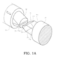
- FIG. 1A is a perspective view illustrating a relationship between a pair of swinging pieces and an operation piece included in an apparatus for manufacturing a non-circular coil according to an embodiment of the present invention, in a state in which the operation piece is removed from between the pair of swinging pieces;
- FIG. 1B is a perspective view illustrating the relationship between the pair of swinging pieces and the operation piece included in the apparatus for manufacturing a non-circular coil according to the embodiment of the present invention, in a state in which the operation piece is inserted between the pair of swinging pieces;
- FIG. 2 is a sectional view taken along the line D-D in FIG. 4 ;
- FIG. 3 is a sectional view illustrating a state in which a wire is wound around a cylindrical bobbin
- FIG. 4 is an enlarged sectional view of a portion A of FIG. 5 ;
- FIG. 5 is a plan view of the apparatus for manufacturing a non-circular coil according to the embodiment of the present invention.
- FIG. 6 is a diagram as viewed from a direction indicated by the arrow B in FIG. 5 ;
- FIG. 7 is a sectional view taken along the line C-C in FIG. 5 ;
- FIG. 8A is a perspective view of the non-circular coil obtained by winding the wire around the cylindrical bobbin in a case where the non-circular coil has an ellipsoidal sectional shape;
- FIG. 8B is a perspective view of the non-circular coil obtained by winding the wire around the cylindrical bobbin in a case where the non-circular coil has an oval sectional shape;
- FIG. 9 is a plan view of a wire shaping device
- FIG. 10 is a sectional view taken along the line E-E in FIG. 9 ;
- FIG. 11 is a sectional view illustrating a state in which the operation piece enters between the pair of swinging pieces to support the cylindrical bobbin;
- FIG. 12 is a sectional view illustrating a state in which the cylindrical bobbin is interposed between a first guide member and a second guide member;
- FIG. 13 is a sectional view illustrating a state in which a clearance is provided between the first guide member and the second guide member so that the wire passes therethrough;
- FIG. 14 is a sectional view illustrating a state in which the wire is wound around the cylindrical bobbin between the first guide member and the second guide member;
- FIG. 15 is a sectional view illustrating a state in which the operation piece is removed from between the pair of swinging pieces
- FIG. 16 is a sectional view illustrating a state in which the pair of swinging pieces is moved with respect to the first guide member to remove the non-circular coil together with the cylindrical bobbin;
- FIG. 17 is a plan view illustrating a state in which the non-circular coil is placed in the wire shaping device
- FIG. 18 is a plan view illustrating a state in which the non-circular coil having the ellipsoidal sectional shape is shaped into the oval sectional shape by using the wire shaping device.
- FIG. 19 is a sectional view illustrating a state in which a wire is wound around a core having an oval cross section by a conventional method.
- An apparatus 10 for manufacturing a non-circular coil (hereinafter also referred to simply as “manufacturing apparatus 10 ”) according to the embodiment of the present invention is used to manufacture a non-circular coil for a voice coil to be used for a small-sized speaker and the like.
- X-, Y-, and Z-axes which perpendicularly cross each other.
- the X-axis extends in an approximately longitudinal direction in a horizontal plane
- the Y-axis extends in an approximately transverse direction in the horizontal plane
- the Z-axis extends in a vertical direction.
- a first support wall 12 and a second support wall 13 are provided on a mount 11 of the manufacturing apparatus 10 so as to stand vertically thereon in parallel to each other in the Y-axis direction at a predetermined distance from each other.
- a first rotary body 26 is provided between the first support wall 12 and the second support wall 13 so as to extend in the Y-axis direction and be movable in the longitudinal direction.
- the first rotary body 26 includes a large-diameter portion 26 a and a small-diameter portion 26 b .
- the large-diameter portion 26 a is a bar-like member having a circular cross section, which is movably supported by the first support wall 12 .
- the small-diameter portion 26 b is a bar-like member having a circular cross section, which is continuously formed coaxially with the large-diameter portion 26 a and is movably supported by the second support wall 13 .
- a core 24 is provided to the first rotary body 26 so as to pass through a center axis thereof.
- the core 24 is a bar-like member having a circular cross section.
- a base member 21 having a columnar shape is provided to a distal end of the core 24 so as to be coaxial therewith.
- a concave portion 26 c ( FIG. 4 ), in which the base member 21 is received, is formed on the large-diameter portion 26 a of the first rotary body 26 .
- the small-diameter portion 26 b is formed so as to have a larger outer diameter than that of the core 24 which is provided coaxially with the base member 21 .
- the core 24 is spline-coupled to the first rotary body 26 , and is movable in the longitudinal direction relative to the first rotary body 26 .
- the core 24 passes through the first rotary body 26 so as not to be rotatable relative to the first rotary body 26 .
- a pair of swinging pieces 22 and 23 is supported by the base member 21 so that the swinging piece 22 is swingable about a shaft 22 a and the swinging piece 23 is swingable about a shaft 23 a .
- the shafts 22 a and 23 a are provided on a base end side.
- the pair of swinging pieces 22 and 23 is formed so that a distance between distal ends thereof can be increased and reduced.
- a gripper 38 and a locking part 39 are provided on a circumference of the large-diameter portion 26 a .
- the gripper 38 grips a winding start end 18 a of a wire 18 .
- the locking part 39 locks a winding finish end 18 b of the wire 18 .
- An operation button 38 a ( FIG. 4 ) for removing the gripped wire 18 from the gripper 38 is provided to the gripper 38 in a projecting manner.
- An operation mechanism (not shown) for operating the operation button 38 a is provided to the mount 11 .
- the manufacturing apparatus 10 includes an operation piece 31 .
- the operation piece 31 is inserted between the distal ends of the pair of swinging pieces 22 and 23 to increase the distance between the distal ends of the pair of swinging pieces 22 and 23 , whereas the operation piece 31 is removed therefrom to reduce the distance.
- a third support wall 17 parallel to the first support wall 12 and the second support wall 13 is provided to stand vertically on the mount 11 at a predetermined distance from the first support wall 12 and the second support wall 13 in the Y-axis direction.
- a second rotary body 32 provided coaxially with the first rotary body 26 is provided on the third support wall 17 to extend in the Y-axis direction so as to be rotatable.
- the operation piece 31 is provided on an end surface of the second rotary body 32 opposed to the pair of swinging pieces 22 and 23 through an intermediation of a second guide member 37 .
- a tapered portion 31 a having a truncated conical shape having an outer diameter reducing toward the pair of swinging pieces 22 and 23 is formed at a distal end of the operation piece 31 .
- a coil spring 29 ( FIG. 4 ) is provided between the swinging pieces 22 and 23 as a biasing member for biasing the pair of swinging pieces 22 and 23 in a direction in which the distance between the distal ends of the swinging pieces 22 and 23 becomes smaller.
- FIG. 11 when the tapered portion 31 a of the operation piece 31 is inserted between the distal ends of the swinging pieces 22 and 23 against the biasing force of the coil spring 29 , the distance between the distal ends of the swinging pieces 22 and 23 is increased ( FIG.
- the manufacturing apparatus 10 includes an insertion/removal mechanism 40 .
- the insertion/removal mechanism 40 moves the pair of swinging pieces 22 and 23 together with the first rotary body 26 to insert the operation piece 31 and remove the operation piece 31 from between the distal ends of the pair of swinging pieces 22 and 23 .
- the insertion/removal mechanism 40 includes a ball screw 42 , a servomotor 43 , and a movable base 44 .
- the ball screw 42 is supported by the first support wall 12 and the second support wall 13 in parallel to the first rotary body 26 .
- the servomotor 43 rotates the ball screw 42 .
- the movable base 44 is threadably fitted over the ball screw 42 to move in the Y-axis direction.
- the first rotary body 26 is mounted so as to be immovable relative to the movable base 44 in the axis direction and rotatable relative thereto. As a result, when the servomotor 43 performs driving to rotate the ball screw 42 to move the movable base 44 in the Y-axis direction, the first rotary body 26 moves in the Y-axis direction together with the movable base 44 .
- the second rotary body 32 does not move. Therefore, the pair of swinging pieces 22 and 23 provided to the first rotary body 26 moves closer to or away from the operation piece 31 provided to the second rotary body 32 .
- the insertion/removal mechanism 40 is driven to move the pair of swinging pieces 22 and 23 closer to the operation piece 31 as described above, the operation piece 31 can be inserted between the distal ends of the swinging pieces 22 and 23 .
- the operation piece 31 can be removed from between the distal ends of the swinging pieces 22 and 23 .
- the manufacturing apparatus 10 includes a winding mechanism.
- the winding mechanism rotates the pair of swinging pieces 22 and 23 having the distal ends, between which the operation piece 31 is inserted, together with the operation piece 31 to wind the wire 18 around an outer circumference of a distal end of the pair of swinging pieces 22 and 23 as a whole, which is enlarged by the insertion of the operation piece 31 between the distal ends of the swinging pieces 22 and 23 (hereinafter referred to simply as “enlarged outer circumference of the distal end of the pair of swinging pieces 22 and 23 ”).
- the winding mechanism includes a first servomotor 14 and a second servomotor 27 .
- the first servomotor 14 rotates the first rotary body 26 together with the core 24 .
- the second servomotor 27 rotates the second rotary body 32 together with the operation piece 31 .
- the first servomotor 14 is mounted to the second support wall 13 .
- a pulley 16 b is coupled to the first rotary body 26
- a pulley 16 a is mounted to a rotary shaft 14 a of the first servomotor 14 .
- a belt 16 c is looped around the pulleys 16 a and 16 b .
- the pulley 16 b is provided to the second support wall 13 so as to be relatively movable in the longitudinal direction of the first rotary body 26 .
- the second servomotor 27 is mounted to the third support wall 17 .
- a pulley 28 b is coupled to the second rotary body 32
- a pulley 28 a is coupled to a rotary shaft 27 a of the second servomotor 27 .
- a belt 28 c is looped around the pulleys 28 a and 28 b .
- the first servomotor 14 and the second servomotor 27 operate in synchronization with each other to rotate both the pair of swinging pieces 22 and 23 and the operation piece 31 in the same direction at the same rotation speed. In this manner, the wire 18 is wound around the enlarged outer circumference of the distal end of the pair of swinging pieces 22 and 23 .
- a wire feeding machine 50 is provided on the mount 11 .
- the wire feeding machine 50 feeds the wire 18 to be wound around the enlarged outer circumference of the distal end of the pair of swinging pieces 22 and 23 .
- the wire feeding machine 50 includes a nozzle 51 , a nozzle moving mechanism 52 , and a tension device 53 .
- the wire 18 passes through the nozzle 51 .
- the nozzle moving mechanism 52 moves the nozzle 51 in three axial directions.
- the tension device 53 applies a tension to the wire 18 .
- the nozzle 51 is fixed to a support plate 54 .
- the nozzle moving mechanism 52 moves the support plate 54 in the three axial directions with respect to the mount 11 .
- the nozzle moving mechanism 52 includes the combination of an X-axis direction expansion actuator 56 , a Y-axis direction expansion actuator 58 , and a Z-axis direction expansion actuator 57 .
- the X-axis direction expansion actuator 56 includes a housing 56 d , a ball screw 56 b , and a follower 56 c .
- the housing 56 d has an elongated box-like shape.
- the ball screw 56 b is provided inside the housing 56 d so as to extend in the longitudinal direction, and is rotationally driven by the servomotor 56 a .
- the follower 56 c is threadably fitted over the ball screw 56 b to move.
- the Z-axis direction expansion actuator 57 includes a housing 57 d , a ball screw 57 b , and a follower 57 c
- the Y-axis direction expansion actuator 58 includes a housing 58 d , a ball screw 58 b , and a follower 58 c
- the servomotor 56 a performs driving to rotate the ball screw 56 b
- the follower 56 c threadably fitted over the ball screw 56 b moves along the longitudinal direction of the housing 56 d
- the functions and the operations of the components of the Z-axis direction expansion actuator 57 and the Y-axis direction expansion actuator 58 are the same as those of the X-axis direction expansion actuator 56 . Therefore, the detailed description thereof is herein omitted.
- the support plate 54 through which the nozzle 51 is provided is mounted to the housing 56 d of the X-axis direction expansion actuator 56 .
- the follower 56 c of the X-axis direction expansion actuator 56 is mounted to the follower 57 c of the Z-axis direction expansion actuator 57 .
- the housing 57 d of the Z-axis direction expansion actuator 57 is mounted to the follower 58 c of the Y-axis direction expansion actuator 58 .
- the housing 58 d of the Y-axis direction expansion actuator 58 extends in the Y-axis direction to be fixed to the mount 11 .
- the servomotors 56 a to 58 a of the respective expansion actuators 56 to 58 are controlled by output signals output from a controller (not shown).
- a cutter device 59 (see Japanese Patent Application Laid-open No. 2011-217824) and a gripping device 60 are provided to the support plate 54 .
- the cutter device 59 cuts the wire 18 passing through the nozzle 51 with an air pressure.
- the gripping device 60 grips the wire 18 with a gripping piece 60 a to inhibit the movement of the wire 18 passing through the nozzle 51 .
- the cutter device 59 is mounted to the support plate 54 through an intermediation of an air cylinder 59 a which is driven by a command from the controller.
- the cutter device 59 is moved by the air cylinder 59 a between a cutting position at which a cutter blade 59 b cuts the wire 18 and a wait position at which the cutter blade 59 b is separated away from the wire 18 .
- the cutter device 59 and the gripping device 60 move together with the nozzle 51 , and are controlled by output signals output from the controller.
- the tension device 53 can apply a tension to the fed wire 18 and pull back the wire 18 .
- the tension device 53 includes a casing 61 , a drum 62 , and a tension bar 63 .
- the casing 61 is provided to the mount 11 .
- the drum 62 and the tension bar 63 are provided on a side surface of the casing 61 in the Y-axis direction.
- the wire 18 is wound around the drum 62 .
- a feeding control motor 64 for rotating the drum 62 to feed the wire 18 is provided inside the casing 61 .
- the wire 18 fed from the drum 62 is guided by a wire guide 63 a provided to a distal end of the tension bar 63 .
- the wire 18 guided by the wire guide 63 a passes from the wire guide 63 a through the nozzle 51 to be wired.
- the tension bar 63 is turnable in the X-axis direction about a turning shaft 63 b at a base end as a fulcrum.
- An angle of turning of the turning shaft 63 b is detected by a potentiometer 65 .
- the potentiometer 65 is provided as turning angle detection means which is received within the casing 61 , and is mounted to the rotary shaft 63 b .
- a detection output of the potentiometer 65 is input to the controller.
- a control signal from the controller is output to the feeding control motor 64 .
- a spring 66 is mounted at a predetermined position between the turning shaft 63 b of the tension bar 63 and the wire guide 63 a through an intermediation of a mounting bracket 63 c .
- the spring 66 is an elastic member provided as biasing means for applying a biasing force in a direction of turning of the tension bar 63 .
- An elastic force in accordance with the turning angle is applied to the tension bar 63 by the spring 66 .
- Another end of the spring 66 is fixed to a moving member 67 .
- the moving member 67 is threadably fitted over a male screw 68 a of a tension adjusting screw 68 .
- a position of the moving member 67 is adjusted in accordance with the rotation of the male screw 68 a .
- the fixed position of the another end of the spring 66 can be displaced.
- the tension on the wire 18 which is applied by the tension bar 63 , is adjusted by the moving member 67 .
- the controller controls the feeding control motor 64 so that the turning angle detected by the potentiometer 65 becomes equal to a predetermined angle.
- the tension device 53 applies the tension to the wire 18 by the spring 66 through the tension bar 63 to rotate the drum 62 so that the turning angle of the tension bar 63 becomes a predetermined angle. In this manner, a predetermined amount of the wire 18 is fed. Thus, the tension of the wire 18 is maintained to a predetermined value.
- the manufacturing apparatus 10 includes a first guide member 36 and the second guide member 37 .
- Base ends of the swinging pieces 22 and 23 are inserted into the first guide member 36 so that the first guide member 36 restricts one side of a winding width of the wire 18 to be wound around a distal end side of the pair of swinging pieces 22 and 23 .
- the distal end side of the pair of swinging pieces 22 and 23 is removably inserted into the second guide member 37 to restrict another side of the winding width of the wire 18 to be wound around the distal end side of the pair of swinging pieces 22 and 23 .
- the first guide member 36 is fastened to an end of the first rotary body 26 by a bolt 36 c , and is provided so as to surround the pair of swinging pieces 22 and 23 .
- the second guide member 37 is fastened to an end of the second rotary body 32 , which faces the pair of swinging pieces 22 and 23 , by a bolt 37 c.
- the manufacturing device 10 for winding the wire 18 around a cylindrical bobbin 19 mounted to the distal end of the pair of swinging pieces 22 and 23 is described.
- a paper bobbin made of a rolled sheet of paper, a resin bobbin made of a resin, and a bobbin made of a non-magnetic thin film are exemplified.
- a resin bobbin made of a polyimide film (trade name: Kapton) is suitable, for example.
- the cylindrical bobbin 19 is supported by the distal end of the pair of swinging pieces 22 and 23 by inserting the operation piece 31 between the distal ends of the swinging pieces 22 and 23 to enlarge the distance between the distal ends of the swinging pieces 22 and 23 , as illustrated in FIG. 11 .
- a first clearance 36 a into which an outer circumferential edge of the cylindrical bobbin 19 on one side moves is formed between the first guide member 36 and the pair of swinging pieces 22 and 23 .
- a second clearance 37 a is formed between the second guide member 37 and the pair of swinging pieces 22 and 23 .
- the remaining portion of the outer circumferential edge of the cylindrical bobbin 19 which does not move into the first clearance 36 a , moves in a state in which the second guide member 37 is held in abutment against the first guide member 36 .
- the outer circumferential edge of the cylindrical bobbin 19 on another side moves into the second clearance 37 a.
- the tapered portion 31 a of the operation piece 31 is inserted between the distal ends of the swinging pieces 22 and 23 to push away the distal ends of the swinging pieces 22 and 23 to enlarge the distance between the distal ends thereof.
- the operation piece 31 is provided to the second rotary body 32 through an intermediation of the second guide member 37 .
- a base end portion 31 b of the operation piece 31 is mounted into a center hole 37 b formed in a center axis of the second guide member 37 to fix the operation piece 31 to the second guide member 37 .
- An intermediate portion 31 c whose sectional shape in the axial direction remains unchanged is formed between the tapered portion 31 a and the base end portion 31 b of the operation piece 31 .
- the pair of swinging pieces 22 and 23 moves along the intermediate portion 31 c of the operation piece 31 even when the pair of swinging pieces 22 and 23 and the operation piece 31 move relative to each other in the axial direction, as illustrated in FIGS. 12 to 14 . Therefore, the distance between the distal ends of the swinging pieces 22 and 23 is neither increased nor reduced.
- the intermediate portion 31 c includes contact surfaces 31 f and 31 g .
- the contact surfaces 31 f and 31 g are held in contact with the swinging pieces 22 and 23 in a state in which the intermediate portion 31 c is inserted between the distal ends of the swinging pieces 22 and 23 .
- both side surfaces 31 d and 31 e of the intermediate portion 31 c which are not held in contact with the pair of swinging pieces 22 and 23 , bulge outward to be curved.
- the side surfaces 31 d and 31 e are formed so as to be continuous with the outer circumferential surfaces of the swinging pieces 22 and 23 around which the wire 18 is wound.
- each of the swinging pieces 22 and 23 around which the wire 18 is wound is formed as an approximately semi-circular shape.
- Each of the side surfaces 31 d and 31 e of the intermediate portion 31 c is formed as a curved surface which bulges outward so as to be continuous with the outer circumferential surfaces of the swinging pieces 22 and 23 having the semi-circular sectional shape.
- the sectional shape of the pair of swinging pieces 22 and 23 which is enlarged by insertion of the operation piece 31 , is a shape like an ellipsoid without a straight-line portion as a whole. Therefore, in this embodiment, the wire 18 is wound around the enlarged outer circumference of the distal end of the pair of swinging pieces 22 and 23 , between which the operation piece 31 is inserted. As a result, a non-circular coil 90 having a shape like an ellipsoid is obtained, as illustrated in FIG. 8A .
- the manufacturing apparatus 10 includes a pull-out mechanism 70 for pulling out the pair of swinging pieces 22 and 23 from the first guide member 36 .
- the pull-out mechanism 70 includes a housing 71 , a ball screw 73 , a follower 74 , and a retaining member 76 .
- the housing 71 is fixed to an upper portion of the movable base 44 so as to extend in the Y-axis direction.
- the ball screw 73 is rotationally driven by a servomotor 72 .
- the follower 74 is threadably fitted over the ball screw 73 to be moved.
- the retaining member 76 is mounted to the follower 74 .
- the pull-out mechanism 70 can move the core 24 in the Y-axis direction through an intermediation of the retaining member 76 . Therefore, the pull-out mechanism 70 can move the core 24 toward the operation piece 31 to project the pair of swinging pieces 22 and 23 from the first guide member 36 , as illustrated in FIG. 15 . At the same time, the pull-out mechanism 70 can move the core 24 away from the operation piece 31 to pull out the pair of swinging pieces 22 and 23 from the first guide member 36 , as illustrated in FIG. 16 .
- a hot-air blower 81 is provided to the mount 11 through an intermediation of an air cylinder 82 .
- An air nozzle 81 a for blowing a hot air is provided to the hot-air blower 81 .
- the hot-air blower 81 moves in a reciprocating manner between a first position (position indicated by an alternate long and short dash line in FIG. 5 ) and a second position (position indicated by a solid line in FIG. 5 ) by driving of the air cylinder 82 .
- a first position position indicated by an alternate long and short dash line in FIG. 5
- a second position position indicated by a solid line in FIG. 5
- the hot-air blower 81 When the hot-air blower 81 is in the second position, the air outlet end of the air nozzle 81 a is separated away from the pair of swinging pieces 22 and 23 .
- the hot-air blower 81 is generally located in the second position.
- the hot-air blower 81 When an insulating coating of the wire 18 wound around the distal end of the pair of swinging pieces 22 and 23 is heated to be melted and is then cooled to be firmly fixed, the hot-air blower 81 is moved from the second position to the first position by the driving of the air cylinder 82 in response to a command from the controller.
- the hot-air blower 81 blows a hot air from the air nozzle 81 a to melt the insulating coating of the wire 18 to be wound so that the insulating coating is firmly fixed.
- the manufacturing apparatus 10 includes a wire shaping device 100 for straightening the wire 18 which is curved to be wound in contact with the side surfaces 31 d and 31 e of the operation piece 31 .
- the wire shaping device 100 includes a base 101 .
- the base 101 is provided with a placement piece 102 .
- the non-circular coil 90 ( FIG. 8A ) obtained by winding the wire 18 around the enlarged outer circumference of the distal end of the pair of swinging pieces 22 and 23 is placed.
- the non-circular coil 90 has an ellipsoidal shape. Therefore, the placement piece 102 includes a support base 102 a and a pair of support pieces 102 b and 102 c ( FIG.
- the support base 102 a supports a lower surface of the non-circular coil 90 .
- the pair of support pieces 102 b and 102 c is provided so as to stand vertically on the support base 102 a , and supports both end portions of the non-circular coil 90 in a long-diameter direction from the inner side.
- the pair of support pieces 102 b and 102 c is immovably fixed to the support base 102 a.
- the wire shaping device 100 includes a pair of pressing members 103 for sandwiching opposing curved portions 90 a ( FIG. 8A ) formed in the non-circular coil 90 from both sides to press the curved portions 90 a therebetween.
- first rails 104 are linearly arranged so as to interpose the placement piece 102 therebetween.
- a first movable base 105 is provided to each of the first rails 104 so as to be movable in a reciprocating manner along the first rail 104 .
- the pressing members 103 are respectively mounted to the first movable bases 105 .
- the wire shaping device 100 includes air cylinders 106 as pressing-member moving actuators for reducing a distance between the pressing members 103 so that the non-circular coil 90 is sandwiched between the pressing members 103 .
- the air cylinder 106 is provided to a mounting base 107 which is provided to an end of each of the first rails 104 in the longitudinal direction to stand vertically on the base 101 .
- a distal end of a rod 106 a of the air cylinder 106 is mounted to the first movable base 105 .
- a projecting piece 103 a which projects toward the non-circular coil 90 is formed on each of the pressing members 103 .
- the rod 106 a projects to move the pressing member 103 forward together with the first movable base 105 .
- the pressing members 103 sandwich the curved portions 90 a ( FIG. 8A ) on both sides of the non-circular coil 90 placed on the placement piece 102 .
- the projecting pieces 103 a of the pressing members 103 come into contact with the curved portions 90 a to correct the curved portions 90 a into a linear shape ( FIG. 18 ).
- the rod 106 a is pulled to move the pressing members 103 backward together with the first movable base 105 .
- micrometers 108 are mounted so as to be shifted from the pressing members 103 .
- the micrometers 108 are provided in parallel to the first rails 104 , respectively.
- Abutment members 109 are provided on the base 101 .
- Distal ends of rotary shafts 108 a of the micrometers 108 respectively come into abutment against the abutment members 109 .
- the wire shaping device 100 includes a pair of support members 113 for sandwiching and holding the non-circular coil 90 in a direction perpendicular to the direction in which the pressing members 103 sandwich the non-circular coil 90 therebetween.
- Second rails 114 which are arranged linearly so as to interpose the placement piece 102 therebetween, are provided on the base 101 so as to perpendicularly cross the first rails 104 .
- a second movable base 115 is provided to each of the second rails 114 so as to be movable in a reciprocating manner along the second rail 114 .
- the support members 113 are mounted to the second movable bases 115 , respectively.
- the wire shaping device 100 includes air cylinders 116 .
- the air cylinders 116 are provided as support-member moving actuators for reducing a distance between the support members 113 so that the pair of support members 113 restricts the extension of the non-circular coil 90 in the direction perpendicular to the direction in which the pressing members 103 sandwich the non-circular coil 90 therebetween, which is caused when the non-circular coil 90 is sandwiched between the pressing members 103 .
- the air cylinder 116 is provided to a mounting base 117 which is provided to an end of each of the second rails 114 in the longitudinal direction to stand vertically on the base 101 .
- a distal end of a rod 116 a of the air cylinder 116 is mounted to the second movable base 115 .
- a projecting piece 113 a which projects toward the non-circular coil 90 is formed on each of the support members 113 .
- micrometers 118 are mounted so as to be shifted from the support members 113 .
- the micrometers 118 are provided in parallel to the second rails 114 , respectively.
- Abutment members 119 are provided on the base 101 . Distal ends of rotary shafts 118 a of the micrometers 118 respectively come into abutment against the abutment members 119 .
- the support members 113 come into contact with the non-circular coil 90 to restrict the extension of the non-circular coil 90 ( FIG. 18 ).
- the amounts of movement of the support members 113 to restrict the extension are adjusted by the micrometers 118 , respectively.
- the non-circular coil 90 obtained by winding the wire 18 around the enlarged outer circumference of the distal end of the pair of swinging pieces 22 and 23 has an ellipsoidal shape. Therefore, the placement piece 102 is provided so that the pair of pressing members 103 is located in a short-diameter direction of the non-circular coil 90 and the pair of support members 113 is located in the long-diameter direction.
- the method of manufacturing a non-circular coil includes an enlarging step, a winding step, a reducing step, and a coil-removing step.
- the operation piece 31 is inserted between the distal ends of the swinging pieces 22 and 23 whose base ends are swingably supported and distal ends are configured to enlarge and reduce the distance therebetween so that the distance between the distal ends of the swinging pieces 22 and 23 is enlarged.
- the winding step the operation piece 31 and the pair of swinging pieces 22 and 23 are rotated so as to wind the wire 18 around the enlarged outer circumference of the distal end of the pair of swinging pieces 22 and 23 by the insertion of the operation piece 31 to form the non-circular coil 90 .
- the operation piece 31 is removed from between the swinging pieces 22 and 23 to reduce the distance between the distal ends of the swinging pieces 22 and 23 around which the non-circular coil 90 is formed.
- the non-circular coil 90 is removed from the reduced outer circumference of the distal end of the pair of swinging pieces 22 and 23 .
- the non-circular coil 90 may be formed around the cylindrical bobbin 19 .
- a bobbin-mounting step of mounting the cylindrical bobbin 19 to the distal end of the pair of swinging pieces 22 and 23 having the reduced distance between the distal ends is performed prior to the enlarging step of enlarging the distance between the distal ends of the swinging pieces 22 and 23 .
- the wire 18 is wound around the outer circumference of the cylindrical bobbin 19 .
- the non-circular coil 90 is removed together with the cylindrical bobbin 19 .
- the case where the non-circular coil 90 having an ellipsoidal shape is formed around the cylindrical bobbin 19 is described. In the following, the steps are respectively described.
- the cylindrical bobbin 19 is mounted to the distal end of the pair of swinging pieces 22 and 23 having the reduced distance between the distal ends.
- the core 24 is moved toward the operation piece 31 through an intermediation of the retaining member 76 to project the pair of swinging pieces 22 and 23 from the first guide member 36 .
- the servomotor 43 of the insertion/removal mechanism 40 illustrated in FIG. 5 the pair of swinging pieces 22 and 23 is moved away from the operation piece 31 to remove the operation piece 31 from between the distal ends of the swinging pieces 22 and 23 .
- the distance between the distal ends of the swinging pieces 22 and 23 is reduced by the biasing force of the coil spring 29 .
- the cylindrical bobbin 19 is mounted to the distal end of the pair of swinging pieces 22 and 23 having the reduced distance between the distal ends.
- the distance between the distal ends of the swinging pieces 22 and 23 is enlarged.
- the cylindrical bobbin 19 is held on the enlarged outer circumference of the distal end of the pair of swinging pieces 22 and 23 .
- the pair of swinging pieces 22 and 23 is moved closer to the operation piece 31 to insert the operation piece 31 between the distal ends of the swinging pieces 22 and 23 .
- the operation piece 31 is inserted between the distal ends of the swinging pieces 22 and 23 to enlarge the distance between the distal ends of the swinging pieces 22 and 23 as illustrated in FIG. 11 .
- the cylindrical bobbin 19 is held on the enlarged outer circumference of the distal end of the pair of swinging pieces 22 and 23 .
- the distal end side of the pair of swinging pieces 22 and 23 is inserted into the second guide member 37 which is provided so as to surround the operation piece 31 . Further, when the operation piece 31 is inserted between the distal ends of the swinging pieces 22 and 23 , the outer circumferential edge of the cylindrical bobbin 19 on the operation piece 31 side moves into the second clearance 37 a formed in the second guide member 37 . Still further, when the operation piece 31 is inserted between the distal ends of the swinging pieces 22 and 23 , the end surface of the first guide member 36 provided around the pair of swinging pieces 22 and 23 and the end surface of the second guide member 37 come into abutment against each other, as illustrated in FIG.
- the outer circumferential edge of the cylindrical bobbin 19 on the side of the pair of swinging pieces 22 and 23 moves into the first clearance 36 a formed in the first guide member 36 .
- the second clearance 37 a into which the remaining portion of the outer circumferential edge of the cylindrical bobbin 19 which does not move into the first clearance 36 a moves, is formed between the second guide member 37 and the pair of swinging pieces 22 and 23 .
- the outer circumferential edge of the cylindrical bobbin 19 on the one side moves into the first clearance 36 a between the first guide member 36 and the pair of swinging pieces 22 and 23
- the outer circumferential edge of the cylindrical bobbin 19 on the another side moves into the second clearance 37 a between the second guide member 37 and the pair of swinging pieces 22 and 23 .
- the axial position of the cylindrical bobbin 19 is determined with respect to the pair of swinging pieces 22 and 23 .
- the wire 18 is wound around the enlarged outer circumference of the distal end of the pair of swinging pieces 22 and 23 to form the non-circular coil 90 ( FIG. 8A ) at the distal end of the pair of swinging pieces 22 and 23 .
- the wire 18 is wound around the outer circumference of the cylindrical bobbin 19 between the first guide member 36 and the second guide member 37 .
- the end portion of the wire 18 fed to pass through the nozzle 51 is gripped as the winding start end 18 a by the gripper 38 .
- the end portion of the wire 18 is gripped by the gripper 38 in the following manner.
- the operation button 38 a is operated by the operation mechanism (not shown) to open the gripper 38 .
- the operation button 38 a of the gripper 38 is operated again. As a result, the wire 18 fed to pass through the nozzle 51 is gripped by the gripper 38 .
- the pair of swinging pieces 22 and 23 is moved together with the first guide member 36 away from the operation piece 31 .
- a clearance into which the wire 18 can move is formed between the first guide member 36 and the second guide member 37 , as illustrated in FIG. 13 .
- the nozzle 51 is moved by the nozzle moving mechanism 52 ( FIGS. 5 and 6 ) to move the wire 18 fed to pass through the nozzle 51 into the clearance between the first guide member 36 and the second guide member 37 .
- the operation piece 31 and the pair of swinging pieces 22 and 23 are rotated by the first servomotor 14 and the second servomotor 27 ( FIG. 5 ) to wind the wire 18 around the outer circumference of the cylindrical bobbin 19 held on the enlarged outer circumference of the distal end of the pair of swinging pieces 22 and 23 .
- the first servomotor 14 and the second servomotor 27 are driven in synchronization with each other to rotate both the operation piece 31 and the pair of swinging pieces 22 and 23 at the same rotation speed in the same direction to wind the wire 18 .
- the winding start end 18 a of the wire 18 fed to pass through the distal end of the nozzle 51 is guided into the clearance between the first guide member 36 and the second guide member 37 so that the wire 18 is wound around the outer circumference of the cylindrical bobbin 19 at a predetermined position in the axial direction.
- a first layer of the non-circular coil 90 is formed as follows. Each time the cylindrical bobbin 19 rotates at 360 degrees, the pair of swinging pieces 22 and 23 is moved together with the first guide member 36 away from the operation piece 31 by driving the servomotor 43 of the insertion/removal mechanism 40 , as indicated by the arrow in broken line in FIG. 14 . In this manner, the clearance between the first guide member 36 and the second guide member 37 is increased by the amount equal to the diameter of the wire 18 . As the first layer of the non-circular coil 90 , the clearance between the first guide member 36 and the second guide member 37 , in which the wire 18 is wound, is increased in accordance with the number of turns of the wire 18 . In this manner, so-called regular winding for winding the wire 18 so as to form the turns of the wire 18 in close contact with each other is performed.
- the operation piece 31 and the pair of swinging pieces 22 and 23 are rotated to wind the wire 18 fed to pass through the nozzle 51 without changing the clearance between the first guide member 36 and the second guide member 37 .
- the winding for second and subsequent layers is performed.
- the nozzle 51 is moved in a reciprocating manner in the Y-axis direction within the range of the clearance between the first guide member 36 and the second guide member 37 , as indicated by the arrow in solid line in FIG. 14 .
- the wire 18 fed to pass through the nozzle 51 is wound over the first layer of the winding formed on the cylindrical bobbin 19 based on the regular winding. In this manner, the outer circumferential edge of the cylindrical bobbin 19 is moved into the first clearance 36 a and the second clearance 37 a to determine the position of the cylindrical bobbin 19 in the axial direction.
- the non-circular coil 90 can be formed over a predetermined range of the cylindrical bobbin 19 .
- the predetermined tension F is applied to the wire 18 by the tension device 53 ( FIG. 6 ). Therefore, the wire 18 on which the tension F is applied is wound around the outer circumference of the pair of swinging pieces 22 and 23 , which is enlarged by the insertion of the operation piece 31 ( FIG. 3 ). Therefore, when the wire 18 is wound around the outer circumference of the pair of swinging pieces 22 and 23 , which is enlarged by the insertion of the operation piece 31 , the wire 18 is pressed not only against the enlarged outer circumference of the pair of swinging pieces 22 and 23 but also against the side surfaces 31 d and 31 e of the operation piece 31 which bulge outward to be curved, by the tension F applied to the wire 18 in the longitudinal direction. Therefore, the wire 18 is prevented from being separated away from the cylindrical bobbin 19 supported by the pair of swinging pieces 22 and 23 to locally bulge. As a result, the wire 18 can be wound around the cylindrical bobbin 19 in close contact therewith.
- the winding finish end 18 b of the wire 18 fed to pass through the nozzle 51 is locked to the locking part 39 , as illustrated in FIG. 15 .
- the wire 18 is wound around the cylindrical bobbin 19 to form the non-circular coil 90 around the cylindrical bobbin 19 .
- the air nozzle 81 a of the hot-air blower 81 illustrated in FIG. 5 is moved from the second position indicated by the solid line to the first position indicated by the alternate long and short dash line to blow a hot air to the non-circular coil 90 ( FIG. 8 ) which is currently being formed or has already been formed.
- the insulating coating of the wire 18 is melt and is firmly fixed to bond the turns of the wire 18 to each other.
- the non-circular coil 90 is bonded to the cylindrical bobbin 19 . Therefore, an event in which the shape of the non-circular coil 90 formed by the regular winding is subsequently deformed can be prevented.
- the air nozzle 81 a is returned from the first position to the second position.
- the distance between the distal ends of the swinging pieces 22 and 23 around which the non-circular coil 90 is formed is reduced, as illustrated in FIG. 15 .
- the distance between the distal ends is reduced by removing the operation piece 31 from between the swinging pieces 22 and 23 .
- the pair of swinging pieces 22 and 23 is moved away from the operation piece 31 to remove the operation piece 31 from between the swinging pieces 22 and 23 .
- the distance between the distal ends of the swinging pieces 22 and 23 is reduced by the biasing force of the coil spring 29 .
- the non-circular coil 90 is removed from the reduced outer circumference of the distal end of the pair of swinging pieces 22 and 23 .
- the non-circular coil 90 is removed together with the cylindrical bobbin 19 .
- the core 24 is moved in the Y-axis direction through an intermediation of the retaining member 76 to pull the pair of swinging pieces 22 and 23 into the interior of the first guide member 36 , as illustrated in FIG. 16 .
- the end of the cylindrical bobbin 19 is locked to the first clearance 36 a of the first guide member 36 to restrict the movement thereof. Therefore, the pair of swinging pieces 22 and 23 is removed from the cylindrical bobbin 19 .
- the non-circular coil 90 is removed together with the cylindrical bobbin 19 locked to the first guide member 36 from the pair of swinging pieces 22 and 23 .
- the operation button 38 a of the gripper 38 is operated by the operation device (not shown) to release, from the gripper 38 , the winding start end 18 a of the wire 18 gripped by the gripper 38 .
- the winding finish end 18 b of the wire 18 locked to the locking part 39 is gripped by the gripping device 60 ( FIG. 6 ).
- the wire 18 between the nozzle 51 and the locking part 39 is cut by the cutter device 59 .
- the non-circular coil 90 formed by winding the wire 18 around the cylindrical bobbin 19 is obtained.
- the obtained non-circular coil 90 has an ellipsoidal shape. Therefore, the wire 18 does not have a straight-line portion.
- a wire straightening step of changing the shape of the non-circular coil 90 is further required.
- the wire straightening step the parts of the wire 18 of the non-circular coil 90 removed from the swinging pieces 22 and 23 , which are curved and wound in contact with the side surfaces 31 d and 31 e of the operation piece 31 , are straightened to provide straight-line portions to the non-circular coil 90 .
- the wire straightening step is performed by using the wire shaping device 100 is described.
- the non-circular coil 90 is placed on the placement piece 102 . Then, as illustrated in FIG. 18 , the opposing curved portions 90 a ( FIG. 8A ) which are formed in the non-circular coil 90 are sandwiched between the pair of pressing members 103 to be pressed therebetween for straightening. At the same time, the extension of the non-circular coil 90 in a direction perpendicular to a direction in which the non-circular coil 90 is sandwiched is restricted by the pair of support members 113 to prevent the size of the non-circular coil 90 from being increased in the longitudinal direction.
- the non-circular coil 90 having the ellipsoidal shape is sandwiched and pressed between the pair of pressing members 103 from both sides in the short-diameter direction.
- the parts of the wire 18 which are curved and wound in contact with the side surfaces 31 d and 31 e of the operation piece 31 , are straightened, while the extension of the wire 18 in the long-diameter direction is restricted by the pair of support members 113 .
- the non-circular coil 90 having an oval shape is obtained.
- the non-circular coil 90 without a straight-line portion is first manufactured as illustrated in FIG. 8A , and then the corresponding portions of the wire 18 are straightened. As a result, the non-circular coil 90 having the oval or square shape with the straight-line portions as illustrated in FIG. 8B can be manufactured. Even in this case, for example, the wire 18 wound while being pressed against the side surfaces 31 d and 31 e of the operation piece 31 , which bulge outward to be curved, is wound around the cylindrical bobbin 19 without bulging. Therefore, the straight-line portions of the non-circular coil 90 having the oval or square shape obtained by shaping the parts of the wire 18 into the straight-line portions do not bulge. Therefore, according to this embodiment, even when the non-circular coil 90 with the straight-line portions having the shape such as an oval or square shape is to be obtained, the wire 18 to be wound can be prevented from bulging.
- the sectional shape of the pair of swinging pieces 22 and 23 having the distance between the distal ends, which is enlarged by the insertion of the operation piece 31 becomes a shape without a straight-line portion as a whole, for example, an ellipsoidal shape.
- the wire 18 is wound around the outer circumference of the pair of swinging pieces 22 and 23 having the distance therebetween enlarged by the insertion of the operation piece 31 , due to the predetermined tension applied in the longitudinal direction of the wire 18 , the wire 18 is pressed against the outer circumference of the pair of swinging pieces 22 and 23 having the increased distance therebetween and the side surfaces 31 d and 31 e of the operation piece 31 which bulge outward to be curved. Therefore, when the wire 18 is wound, the wire 18 is prevented from separating way from the outer circumference of the pair of swinging pieces 22 and 23 and the side surfaces 31 d and 31 e of the operation piece 31 to bulge.
- the non-circular coil 90 which is obtained by winding the wire 18 around the outer circumference of the pair of swinging pieces 22 and 23 having the distance therebetween enlarged by the insertion of the operation piece 31 , has a shape without a straight-line portion, such as an ellipsoidal shape.
- a non-circular coil having an oval or square shape is to be manufactured, however, the shape of the non-circular coil 90 having a shape such as an ellipsoidal shape is changed to obtain the non-circular coil with straight-line portions having a shape such as an oval or square shape.
- the wire 18 wound while being pressed against the side surfaces 31 d and 31 e of the operation piece 31 which bulge outward to be curved, does not bulge. Therefore, the straight-line portions of the non-circular coil 90 having an oval or square shape obtained by subsequently changing the parts of the wire 18 into the straight-line portions do not bulge. Therefore, according to this embodiment, even when the non-circular coil 90 with the straight-line portions having a shape such as an oval or square shape is to be obtained, the wire 18 to be wound can be prevented from bulging.
- the wire 18 When the wire 18 is wound, the wire 18 is wound around the outer circumference of the pair of swinging pieces 22 and 23 under the predetermined tension applied by the tension device 53 .
- the distance between the distal ends of the swinging pieces 22 and 23 , around which the wire 18 is wound, is reduced as illustrated in FIG. 15 . Therefore, the clearance is generated between the outer circumference of the distal end of the pair of swinging pieces 22 and 23 and an inner circumference of the cylindrical bobbin 19 .
- the outer circumference of the distal end of the pair of swinging pieces 22 and 23 and the inner circumference of the cylindrical bobbin 19 are prevented from significantly slide against each other. Accordingly, the non-circular coil 90 can be relatively easily removed from the pair of swinging pieces 22 and 23 without damaging the coating of the wire 18 .
- the wire 18 is wound around the cylindrical bobbin 19 in a state in which the outer circumference edge of the cylindrical bobbin 19 on the one side moves into the first clearance 36 a between the first guide member 36 and the pair of swinging pieces 22 and 23 and the outer circumference edge of the cylindrical bobbin 19 on the another side moves into the second clearance 37 a between the second guide member 37 and the pair of swinging pieces 22 and 23 . Therefore, the wire 18 can be wound over the desired range of the cylindrical bobbin 19 .
- the non-circular coil 90 is removed from the pair of swinging pieces 22 and 23 by pulling the pair of swinging pieces 22 and 23 into the interior of the first guide member 36 in a state in which the movement of the cylindrical bobbin 19 is restricted by the first guide member 36 . Therefore, the non-circular coil 90 can be easily removed from the pair of swinging pieces 22 and 23 .
- the wire 18 may be directly wound around the pair of swinging pieces 22 and 23 without using the cylindrical bobbin 19 to form the non-circular coil 90 on the outer circumference of the pair of swinging pieces 22 and 23 .
- the distance between the distal ends of the swinging pieces 22 and 23 , around which the wire 18 is wound, is reduced when the non-circular coil 90 formed by winding the wire 18 around the pair of swinging pieces 22 and 23 is removed from the pair of swinging pieces 22 and 23 .
- the clearance is generated between the outer circumference of the distal end of the pair of swinging pieces 22 and 23 and the inner circumference of the non-circular coil 90 .
- the surface coating on the inner circumference of the non-circular coil 90 and the outer circumference of the distal end of the pair of swinging pieces 22 and 23 are prevented from significantly slide against each other. Accordingly, even when the non-circular coil 90 is formed directly on the outer circumference of the pair of swinging pieces 22 and 23 , the non-circular coil 90 can be relatively easily removed from the pair of swinging pieces 22 and 23 without damaging the coating of the wire 18 .
- the sectional shape of the pair of swinging pieces 22 and 23 having the increased distance between the distal ends by the insertion of the operation piece 31 is ellipsoidal and the obtained non-circular coil 90 has the ellipsoidal shape has been described.
- the sectional shape of the pair of swinging pieces 22 and 23 having the increased distance by the insertion of the operation piece 31 may be any shape as long as the side surfaces 31 d and 31 e of the operation piece 31 inserted between the distal ends of the swinging pieces 22 and 23 bulge outward to be curved and are formed so as to be continuous with the outer circumferential surfaces of the swinging pieces 22 and 23 so that the sectional shape does not have a straight-line portion as a whole.
- the sectional shape of the pair of swinging pieces 22 and 23 may be a rounded square.
- the insertion/removal mechanism 40 may have any configuration as long as the operation piece 31 is inserted and removed from between the distal ends of the swinging pieces 22 and 23 .
- the insertion/removal mechanism 40 may have a configuration for moving the operation piece 31 in the axial direction.
Landscapes
- Engineering & Computer Science (AREA)
- Power Engineering (AREA)
- Manufacturing & Machinery (AREA)
- Manufacture Of Motors, Generators (AREA)
- Wire Processing (AREA)
- Audible-Bandwidth Dynamoelectric Transducers Other Than Pickups (AREA)
- Coil Winding Methods And Apparatuses (AREA)
- Media Introduction/Drainage Providing Device (AREA)
Applications Claiming Priority (2)
| Application Number | Priority Date | Filing Date | Title |
|---|---|---|---|
| JP2012142758A JP5995355B2 (ja) | 2012-06-26 | 2012-06-26 | 非円形コイルの製造装置及び非円形コイルの製造方法 |
| JP2012-142758 | 2012-06-26 |
Publications (2)
| Publication Number | Publication Date |
|---|---|
| US20130341454A1 US20130341454A1 (en) | 2013-12-26 |
| US9240277B2 true US9240277B2 (en) | 2016-01-19 |
Family
ID=48672468
Family Applications (1)
| Application Number | Title | Priority Date | Filing Date |
|---|---|---|---|
| US13/926,196 Active 2033-10-06 US9240277B2 (en) | 2012-06-26 | 2013-06-25 | Apparatus and method for manufacturing non-circular coil |
Country Status (5)
| Country | Link |
|---|---|
| US (1) | US9240277B2 (de) |
| EP (1) | EP2680283B1 (de) |
| JP (1) | JP5995355B2 (de) |
| CN (1) | CN103515086B (de) |
| TW (1) | TWI447761B (de) |
Families Citing this family (9)
| Publication number | Priority date | Publication date | Assignee | Title |
|---|---|---|---|---|
| JP6271204B2 (ja) * | 2013-09-30 | 2018-01-31 | 株式会社東芝 | 巻線装置、巻線方法 |
| CN105118659B (zh) * | 2015-07-28 | 2017-01-25 | 安徽亿民照明股份有限公司 | 电感绕线机 |
| ITUB20159353A1 (it) * | 2015-12-22 | 2017-06-22 | Marsilli & Co | Mandrino con attacco rapido, particolarmente per macchine per l'avvolgimento di bobine elettriche. |
| CN109511055B (zh) * | 2018-08-31 | 2024-02-09 | 东莞市冠威机械有限公司 | 自动化音圈生产设备 |
| JP7373891B2 (ja) * | 2019-05-09 | 2023-11-06 | Nittoku株式会社 | コイル挿入装置及びコイル挿入方法 |
| CN110942910B (zh) * | 2019-12-18 | 2021-07-16 | 江苏立讯机器人有限公司 | 一种绕线装置 |
| CN111115374A (zh) * | 2019-12-30 | 2020-05-08 | 苏州绿控新能源科技有限公司 | 一种匀线速的绕线方法 |
| EP3885104B1 (de) * | 2020-03-24 | 2024-06-12 | Assa Abloy AB | Spulenpolymerisierung während des wickelprozesses durch heissluft |
| CN113205958B (zh) * | 2021-04-26 | 2023-01-31 | 骏日科技(深圳)有限公司 | 球面线圈的绕制装置及方法 |
Citations (11)
| Publication number | Priority date | Publication date | Assignee | Title |
|---|---|---|---|---|
| US3672040A (en) * | 1970-06-01 | 1972-06-27 | Gen Electric | Method of developing coils of a coil group for a magnetic core |
| US5076508A (en) * | 1990-01-19 | 1991-12-31 | Advanced Machine And Tool Corporation | Start wire positioning method and apparatus |
| JPH09148168A (ja) | 1995-11-24 | 1997-06-06 | Matsushita Electric Ind Co Ltd | 巻線装置 |
| US20050133655A1 (en) | 2002-08-08 | 2005-06-23 | Shingo Hashimoto | Coil forming method and coil forming device |
| US20080001016A1 (en) | 2004-08-27 | 2008-01-03 | Koninklijke Philips Electronics N.V. | Method of Manufacturing a Coil |
| TW200811024A (en) | 2006-05-26 | 2008-03-01 | Nittoku Eng | Wire winding system, tension device, and wire winding method |
| JP2008244472A (ja) | 2007-03-01 | 2008-10-09 | Nippon Saabitsuku Kk | コイルの取出しと成形に係る方法又は装置 |
| JP2009049357A (ja) | 2007-07-24 | 2009-03-05 | Nippon Saabitsuku Kk | コイルの取出し又は取出し成形に係る方法又は装置 |
| US20090090807A1 (en) | 2007-10-04 | 2009-04-09 | Keihin Corporation | Coil winding system and method for fabricating molded coil |
| JP2010004589A (ja) | 2008-06-18 | 2010-01-07 | Denso Corp | コイル巻取り装置 |
| JP2012004483A (ja) | 2010-06-21 | 2012-01-05 | Nittoku Eng Co Ltd | 巻線機及び空芯コイルの製造方法 |
Family Cites Families (10)
| Publication number | Priority date | Publication date | Assignee | Title |
|---|---|---|---|---|
| US3371876A (en) * | 1966-01-24 | 1968-03-05 | Gen Electric | Coil winding machine |
| JPS4740371Y1 (de) * | 1969-03-05 | 1972-12-06 | ||
| JPS54132753U (de) * | 1978-03-08 | 1979-09-14 | ||
| JPS60720A (ja) * | 1983-06-17 | 1985-01-05 | Hitachi Ltd | コイル製造方法および製造治具 |
| CN2054562U (zh) * | 1989-09-13 | 1990-03-14 | 博山电机厂 | 开合式绕线模 |
| JP4739821B2 (ja) * | 2005-06-02 | 2011-08-03 | 株式会社エス・エッチ・ティ | 自動巻線機及びこれを用いた空心コイルの製造方法 |
| JP2007180360A (ja) * | 2005-12-28 | 2007-07-12 | Nittoku Eng Co Ltd | コアレスコイルの製造装置及び製造方法 |
| WO2008108312A1 (ja) * | 2007-03-01 | 2008-09-12 | Nippon Serbig Co., Ltd | コイルの取出しと成形に係る方法又は装置 |
| JP5460432B2 (ja) | 2010-04-06 | 2014-04-02 | 日特エンジニアリング株式会社 | 開閉動作装置及び対象物の切断方法 |
| JP5508156B2 (ja) * | 2010-06-21 | 2014-05-28 | 日特エンジニアリング株式会社 | 非円形コイルの製造装置及びその製造方法 |
-
2012
- 2012-06-26 JP JP2012142758A patent/JP5995355B2/ja active Active
-
2013
- 2013-06-24 TW TW102122339A patent/TWI447761B/zh active
- 2013-06-25 US US13/926,196 patent/US9240277B2/en active Active
- 2013-06-25 EP EP13173523.5A patent/EP2680283B1/de active Active
- 2013-06-26 CN CN201310259860.2A patent/CN103515086B/zh active Active
Patent Citations (13)
| Publication number | Priority date | Publication date | Assignee | Title |
|---|---|---|---|---|
| US3672040A (en) * | 1970-06-01 | 1972-06-27 | Gen Electric | Method of developing coils of a coil group for a magnetic core |
| US5076508A (en) * | 1990-01-19 | 1991-12-31 | Advanced Machine And Tool Corporation | Start wire positioning method and apparatus |
| JPH09148168A (ja) | 1995-11-24 | 1997-06-06 | Matsushita Electric Ind Co Ltd | 巻線装置 |
| US20050133655A1 (en) | 2002-08-08 | 2005-06-23 | Shingo Hashimoto | Coil forming method and coil forming device |
| US7311284B2 (en) * | 2002-08-08 | 2007-12-25 | Aisin Aw Co., Ltd. | Coil forming method and coil forming device |
| JP2008511150A (ja) | 2004-08-27 | 2008-04-10 | コーニンクレッカ フィリップス エレクトロニクス エヌ ヴィ | コイルの製造方法 |
| US20080001016A1 (en) | 2004-08-27 | 2008-01-03 | Koninklijke Philips Electronics N.V. | Method of Manufacturing a Coil |
| TW200811024A (en) | 2006-05-26 | 2008-03-01 | Nittoku Eng | Wire winding system, tension device, and wire winding method |
| JP2008244472A (ja) | 2007-03-01 | 2008-10-09 | Nippon Saabitsuku Kk | コイルの取出しと成形に係る方法又は装置 |
| JP2009049357A (ja) | 2007-07-24 | 2009-03-05 | Nippon Saabitsuku Kk | コイルの取出し又は取出し成形に係る方法又は装置 |
| US20090090807A1 (en) | 2007-10-04 | 2009-04-09 | Keihin Corporation | Coil winding system and method for fabricating molded coil |
| JP2010004589A (ja) | 2008-06-18 | 2010-01-07 | Denso Corp | コイル巻取り装置 |
| JP2012004483A (ja) | 2010-06-21 | 2012-01-05 | Nittoku Eng Co Ltd | 巻線機及び空芯コイルの製造方法 |
Non-Patent Citations (3)
| Title |
|---|
| Extended European Search Report issued Sep. 9, 2014, corresponding European patent application No. 13173523.5. |
| Office Action dated Jul. 21, 2015, corresponding to Chinese patent application No. 201310259860.2. |
| Office Action issued May 29, 2014, corresponds to Taiwanese patent application No. 102122339. |
Also Published As
| Publication number | Publication date |
|---|---|
| CN103515086B (zh) | 2016-08-17 |
| EP2680283A2 (de) | 2014-01-01 |
| US20130341454A1 (en) | 2013-12-26 |
| JP2014007322A (ja) | 2014-01-16 |
| JP5995355B2 (ja) | 2016-09-21 |
| CN103515086A (zh) | 2014-01-15 |
| TWI447761B (zh) | 2014-08-01 |
| EP2680283B1 (de) | 2015-06-17 |
| TW201401308A (zh) | 2014-01-01 |
| EP2680283A3 (de) | 2014-10-08 |
Similar Documents
| Publication | Publication Date | Title |
|---|---|---|
| US9240277B2 (en) | Apparatus and method for manufacturing non-circular coil | |
| US9607761B2 (en) | Winding device and method for binding wire material to terminal | |
| US9704645B2 (en) | Coil manufacturing apparatus | |
| EP2682961B1 (de) | Drahtwickelvorrichtung und Drahtwickelverfahren | |
| US10347420B2 (en) | Winding device and winding method | |
| TWI625177B (zh) | 彈簧製造方法及執行此方法的彈簧機 | |
| TWI575543B (zh) | Coil manufacturing device | |
| JP6257083B2 (ja) | コイル成形装置及びコイル成形方法 | |
| CN102315010B (zh) | 非圆形线圈的制造装置及其制造方法 | |
| JP6315808B2 (ja) | コイル製造装置 | |
| CN106981363B (zh) | 线圈制造装置以及线圈制造方法 | |
| CN111052278A (zh) | 绕线装置以及使用该绕线装置的绕线方法 | |
| CN102126285B (zh) | 管材螺旋槽加工装置和管材螺旋槽加工方法 | |
| JP5680912B2 (ja) | トロイダルコイルの製造装置 | |
| JP2016046331A (ja) | コイル製造装置及びコイル製造方法 | |
| JP2013055228A (ja) | 空芯コイルの巻線装置および巻線方法 | |
| JP6442737B2 (ja) | コイルの巻線方法および巻線装置 | |
| JPH05285092A (ja) | 熱可塑性樹脂チューブ表面溝加工方法及び加工装置 | |
| JPH09167712A (ja) | 点火コイルの磁芯作成用治具および磁芯作成方法 |
Legal Events
| Date | Code | Title | Description |
|---|---|---|---|
| AS | Assignment |
Owner name: NITTOKU ENGINEERING CO., LTD., JAPAN Free format text: ASSIGNMENT OF ASSIGNORS INTEREST;ASSIGNOR:OSAWA, MASUMI;REEL/FRAME:030680/0737 Effective date: 20130613 |
|
| FEPP | Fee payment procedure |
Free format text: PAT HOLDER NO LONGER CLAIMS SMALL ENTITY STATUS, ENTITY STATUS SET TO UNDISCOUNTED (ORIGINAL EVENT CODE: STOL); ENTITY STATUS OF PATENT OWNER: LARGE ENTITY |
|
| STCF | Information on status: patent grant |
Free format text: PATENTED CASE |
|
| MAFP | Maintenance fee payment |
Free format text: PAYMENT OF MAINTENANCE FEE, 4TH YEAR, LARGE ENTITY (ORIGINAL EVENT CODE: M1551); ENTITY STATUS OF PATENT OWNER: LARGE ENTITY Year of fee payment: 4 |
|
| MAFP | Maintenance fee payment |
Free format text: PAYMENT OF MAINTENANCE FEE, 8TH YEAR, LARGE ENTITY (ORIGINAL EVENT CODE: M1552); ENTITY STATUS OF PATENT OWNER: LARGE ENTITY Year of fee payment: 8 |