US9242367B2 - Magnetic drill press - Google Patents
Magnetic drill press Download PDFInfo
- Publication number
- US9242367B2 US9242367B2 US14/256,255 US201414256255A US9242367B2 US 9242367 B2 US9242367 B2 US 9242367B2 US 201414256255 A US201414256255 A US 201414256255A US 9242367 B2 US9242367 B2 US 9242367B2
- Authority
- US
- United States
- Prior art keywords
- magnet assembly
- drill press
- magnetic drill
- magnetic
- rotatable
- Prior art date
- Legal status (The legal status is an assumption and is not a legal conclusion. Google has not performed a legal analysis and makes no representation as to the accuracy of the status listed.)
- Active
Links
- 230000005291 magnetic effect Effects 0.000 title claims abstract description 109
- 230000005540 biological transmission Effects 0.000 claims abstract description 49
- 230000005294 ferromagnetic effect Effects 0.000 claims abstract description 29
- 230000033001 locomotion Effects 0.000 claims abstract description 9
- 230000007423 decrease Effects 0.000 claims description 6
- 230000004907 flux Effects 0.000 description 4
- 238000005553 drilling Methods 0.000 description 2
- 238000010276 construction Methods 0.000 description 1
- 230000003247 decreasing effect Effects 0.000 description 1
- 239000003302 ferromagnetic material Substances 0.000 description 1
- 239000000696 magnetic material Substances 0.000 description 1
- 229910001172 neodymium magnet Inorganic materials 0.000 description 1
- 229910052755 nonmetal Inorganic materials 0.000 description 1
Images


Classifications
-
- B—PERFORMING OPERATIONS; TRANSPORTING
- B25—HAND TOOLS; PORTABLE POWER-DRIVEN TOOLS; MANIPULATORS
- B25H—WORKSHOP EQUIPMENT, e.g. FOR MARKING-OUT WORK; STORAGE MEANS FOR WORKSHOPS
- B25H1/00—Work benches; Portable stands or supports for positioning portable tools or work to be operated on thereby
- B25H1/0021—Stands, supports or guiding devices for positioning portable tools or for securing them to the work
- B25H1/0057—Devices for securing hand tools to the work
- B25H1/0064—Stands attached to the workpiece
- B25H1/0071—Stands attached to the workpiece by magnetic means
-
- B—PERFORMING OPERATIONS; TRANSPORTING
- B23—MACHINE TOOLS; METAL-WORKING NOT OTHERWISE PROVIDED FOR
- B23Q—DETAILS, COMPONENTS, OR ACCESSORIES FOR MACHINE TOOLS, e.g. ARRANGEMENTS FOR COPYING OR CONTROLLING; MACHINE TOOLS IN GENERAL CHARACTERISED BY THE CONSTRUCTION OF PARTICULAR DETAILS OR COMPONENTS; COMBINATIONS OR ASSOCIATIONS OF METAL-WORKING MACHINES, NOT DIRECTED TO A PARTICULAR RESULT
- B23Q3/00—Devices holding, supporting, or positioning work or tools, of a kind normally removable from the machine
- B23Q3/15—Devices for holding work using magnetic or electric force acting directly on the work
- B23Q3/154—Stationary devices
- B23Q3/1546—Stationary devices using permanent magnets
-
- B—PERFORMING OPERATIONS; TRANSPORTING
- B23—MACHINE TOOLS; METAL-WORKING NOT OTHERWISE PROVIDED FOR
- B23Q—DETAILS, COMPONENTS, OR ACCESSORIES FOR MACHINE TOOLS, e.g. ARRANGEMENTS FOR COPYING OR CONTROLLING; MACHINE TOOLS IN GENERAL CHARACTERISED BY THE CONSTRUCTION OF PARTICULAR DETAILS OR COMPONENTS; COMBINATIONS OR ASSOCIATIONS OF METAL-WORKING MACHINES, NOT DIRECTED TO A PARTICULAR RESULT
- B23Q17/00—Arrangements for observing, indicating or measuring on machine tools
- B23Q17/24—Arrangements for observing, indicating or measuring on machine tools using optics or electromagnetic waves
- B23Q17/2404—Arrangements for improving direct observation of the working space, e.g. using mirrors or lamps
-
- F—MECHANICAL ENGINEERING; LIGHTING; HEATING; WEAPONS; BLASTING
- F16—ENGINEERING ELEMENTS AND UNITS; GENERAL MEASURES FOR PRODUCING AND MAINTAINING EFFECTIVE FUNCTIONING OF MACHINES OR INSTALLATIONS; THERMAL INSULATION IN GENERAL
- F16H—GEARING
- F16H35/00—Gearings or mechanisms with other special functional features
- F16H2035/003—Gearings comprising pulleys or toothed members of non-circular shape, e.g. elliptical gears
-
- Y—GENERAL TAGGING OF NEW TECHNOLOGICAL DEVELOPMENTS; GENERAL TAGGING OF CROSS-SECTIONAL TECHNOLOGIES SPANNING OVER SEVERAL SECTIONS OF THE IPC; TECHNICAL SUBJECTS COVERED BY FORMER USPC CROSS-REFERENCE ART COLLECTIONS [XRACs] AND DIGESTS
- Y10—TECHNICAL SUBJECTS COVERED BY FORMER USPC
- Y10T—TECHNICAL SUBJECTS COVERED BY FORMER US CLASSIFICATION
- Y10T408/00—Cutting by use of rotating axially moving tool
- Y10T408/55—Cutting by use of rotating axially moving tool with work-engaging structure other than Tool or tool-support
- Y10T408/554—Magnetic or suction means
-
- Y—GENERAL TAGGING OF NEW TECHNOLOGICAL DEVELOPMENTS; GENERAL TAGGING OF CROSS-SECTIONAL TECHNOLOGIES SPANNING OVER SEVERAL SECTIONS OF THE IPC; TECHNICAL SUBJECTS COVERED BY FORMER USPC CROSS-REFERENCE ART COLLECTIONS [XRACs] AND DIGESTS
- Y10—TECHNICAL SUBJECTS COVERED BY FORMER USPC
- Y10T—TECHNICAL SUBJECTS COVERED BY FORMER US CLASSIFICATION
- Y10T408/00—Cutting by use of rotating axially moving tool
- Y10T408/65—Means to drive tool
- Y10T408/675—Means to drive tool including means to move Tool along tool-axis
- Y10T408/6779—Rack and pinion
-
- Y—GENERAL TAGGING OF NEW TECHNOLOGICAL DEVELOPMENTS; GENERAL TAGGING OF CROSS-SECTIONAL TECHNOLOGIES SPANNING OVER SEVERAL SECTIONS OF THE IPC; TECHNICAL SUBJECTS COVERED BY FORMER USPC CROSS-REFERENCE ART COLLECTIONS [XRACs] AND DIGESTS
- Y10—TECHNICAL SUBJECTS COVERED BY FORMER USPC
- Y10T—TECHNICAL SUBJECTS COVERED BY FORMER US CLASSIFICATION
- Y10T408/00—Cutting by use of rotating axially moving tool
- Y10T408/65—Means to drive tool
- Y10T408/675—Means to drive tool including means to move Tool along tool-axis
- Y10T408/6786—Manually moved lever
Definitions
- the present invention relates to power tools, and more specifically to magnetic drill presses.
- Magnetic drill presses perform drilling operations by latching a magnetic base of the drill press to a ferromagnetic workpiece.
- Such magnetic bases use electromagnets or permanent magnets for generating a magnetic field.
- a magnetic base with permanent magnets typically physically reorient at least some of the permanent magnets to switch the base between a latched configuration and a release configuration.
- the invention provides, in one aspect, a magnetic drill press including a main housing, a drill unit supported by the main housing for relative movement therewith in a direction of a rotational axis of the drill unit, and a base coupled to the main housing for selectively magnetically latching to a ferromagnetic workpiece.
- the base includes a magnet holder, a fixed magnet assembly supported within the magnet holder, a rotatable magnet assembly supported within the magnet holder, and a transmission.
- the transmission includes an input, an output coupled to the rotatable magnet assembly for rotating the rotatable magnet assembly relative to the fixed magnet assembly through a predetermined rotation angle, and a gear train positioned between the output and the input.
- the gear train is configured to provide a variable gear ratio between the output and the input during at least a portion of the predetermined rotation angle.
- the invention provides, in another aspect, a magnetic drill press including a main housing, a drill unit supported by the main housing for relative movement therewith in a direction of a rotational axis of the drill unit, and a magnetic base coupled to the main housing for selectively magnetically latching to a ferromagnetic workpiece.
- the base including a plurality of grooves formed on a surface of the base engageable with the ferromagnetic workpiece.
- the invention provides, in another aspect, a magnetic base for selectively magnetically latching to a ferromagnetic surface.
- the magnetic base includes a magnet holder, a fixed magnet assembly supported within the magnet holder, a movable magnet assembly supported within the magnet holder, and a transmission.
- the transmission includes an input, an output coupled to the movable magnet assembly for moving the movable magnet assembly relative to the fixed magnet assembly through a predetermined range of motion, and a plurality of transmission elements positioned between the output and the input.
- the elements are configured to provide a variable mechanical advantage between the output and the input during at least a portion of the predetermined range of motion.
- FIG. 1 is a perspective view of a magnetic drill press including a magnetic base in accordance with an embodiment of the invention.
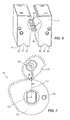
- FIG. 2 is a rear perspective view of the magnetic base of FIG. 1 .
- FIG. 3 is an exploded front perspective view of the magnetic base of FIG. 2 .
- FIG. 4 is an exploded rear perspective view of the magnetic base of FIG. 2 .
- FIG. 5A is a cross-sectional view of the magnetic base of FIG. 2 in a latching configuration taken along the line 5 A- 5 A in FIG. 2 .
- FIG. 5B is a cross-sectional view of the magnetic base of FIG. 2 in a release configuration.
- FIG. 5C is a cross-sectional view of the magnetic base of FIG. 2 in the latching configuration, magnetically latched to a workpiece.
- FIG. 6 is a perspective view of a magnet holder of the magnetic base of FIG. 2 .
- FIG. 7 is a front view of a gear train of the magnetic base of FIG. 2 .
- FIG. 8A is a perspective view of a transmission including the gear train of FIG. 7 , a rotatable magnet assembly coupled to the transmission, and a fixed magnet assembly of the magnetic base of FIG. 2 , illustrating the rotatable magnet assembly in a position coinciding with the latching configuration of the magnetic base.
- FIG. 8B is a perspective view of the transmission, the rotatable magnet assembly, and the fixed magnet assembly of FIG. 8A , illustrating the rotatable magnet assembly in a position between the latching configuration and the release configuration of the magnetic base.
- FIG. 8C is a perspective view of the transmission, the rotatable magnet assembly, and the fixed magnet assembly of FIG. 8A , illustrating the rotatable magnet assembly in a position coinciding with the release configuration of the magnetic base.
- FIG. 9 is a chart comparing torque and gear ratio as a function of rotation angle of the rotatable magnet assembly of FIG. 8A .
- FIG. 10 is a chart comparing magnetic holding force as a function of workpiece thickness of the magnet holder of FIG. 2 .
- FIG. 11 is a rear perspective view of a battery receptacle of the magnetic drill press of FIG. 1 .
- FIG. 12 is a bottom perspective view of the magnetic drill press of FIG. 1 including an adapter for mounting the magnetic drill press on a non-flat surface.
- FIG. 13 is an exploded, bottom perspective view of the magnetic base and the adapter of FIG. 12 .
- FIG. 14 is a cross-sectional view of the magnetic base and the adapter of FIG. 12 .
- FIG. 1 illustrates a magnetic drill press 10 including a drill unit 14 , a main housing 18 to support the drill unit 14 , and a magnetic base 22 coupled to the main housing 18 and selectively magnetically latching the magnetic drill press 10 to a ferromagnetic workpiece (not shown).
- the drill unit 14 may include a DC motor or an AC motor to rotate a spindle with a working tool 26 attached thereto about a rotational axis 28 .
- the drill unit 14 is supported by the main housing 18 for relative movement therewith in a direction along the rotational axis 28 .
- the magnetic drill press 10 may be powered by a battery 30 as shown in the illustrated embodiment, from an AC voltage input (i.e., from a wall outlet), or by an alternative DC voltage input (e.g., a DC power supply).
- the battery 30 is selectively electrically connected with the drill unit 14 , and the main housing 18 includes a receptacle 31 in which the battery 30 is at least partially received. In the illustrated embodiment, a majority of the battery 30 is contained within the receptacle 31 .
- the receptacle 31 is defined by two side walls 146 , a rear wall 150 , a front wall 154 , and a bottom wall 162 . These walls 146 , 150 , 154 , 162 protect and shield the battery 30 from impacts, and in the illustrated embodiment, all but one side of the battery 30 is at least partially shielded within the receptacle 31 .
- a power cord 32 extends between the main housing 18 and the drill unit 14 for delivering power from the battery 30 to the drill unit 14 .
- the power cord 32 forms a loop with a bottom portion 33 proximate the base 22 .
- the magnetic base 22 includes a magnet holder 34 , a fixed magnet assembly 38 supported within the magnet holder 34 , and a rotatable magnet assembly 42 supported within the magnet holder 34 and spaced from the fixed magnet assembly 38 .
- the magnet assembly 42 is rotatable with respect to the fixed magnet assembly 38 , but in alternative embodiments the magnet assembly 42 may be movable with respect to the fixed magnet assembly 38 in other ways (e.g., translation, rotation and translation, etc.).
- the magnet holder 34 includes an end plate 46 to secure the rotatable magnet assembly 42 and the fixed magnet assembly 38 within the magnet holder 34 .
- the rotatable magnet assembly 42 in the illustrated embodiment includes a rotatable drum 50 and four permanent magnets 54 (e.g., Neodymium magnets) affixed to the rotatable drum 50 .
- the fixed magnet assembly 38 includes four trapezoidal permanent magnets 58 secured within the magnet holder 34 in the illustrated embodiment.
- the rotatable magnet assembly and the fixed magnet assembly may each include one or more permanent magnets.
- the trapezoidal permanent magnets 58 each include a north (N) and a south (S) pole that are laterally spaced with respect to a longitudinal axis 62 of the magnetic base 22 .
- the permanent magnets 54 of the rotatable magnet assembly 42 each include a north (N) and a south (S) pole that are laterally spaced with respect to the longitudinal axis 62 in the positions shown in FIGS. 5A and 5B .
- the magnet holder 34 includes bores 63 in which to receive and store fasteners 64 , the use of which is explained in further detail below.
- the magnet holder 34 is shown with the rotatable magnet assembly 42 and the fixed magnet assembly 38 removed to better illustrate the geometry of the magnet holder 34 .
- the magnet holder 34 in the illustrated embodiment includes ridges 66 and grooves 67 defined between adjacent ridges 66 formed on a bottom surface 70 (i.e., the surface that engages the ferromagnetic workpiece).
- the magnet holder 34 includes four ridges 66 and two grooves 67 , the importance of which is described in greater detail below.
- the magnet holder 34 includes slots 74 formed between the rotatable magnet assembly 42 and the fixed magnet assembly 38 .
- the magnetic base 22 further includes a transmission 78 having an input 82 , an output 86 , and a plurality of transmission elements (e.g., a gear train 90 ) positioned between the output 86 and the input 82 .
- the gear train 90 is configured to provide a variable mechanical advantage (e.g., a variable gear ratio) between the output 86 and the input 82 .
- the transmission 78 also includes a cover 94 enclosing the gear train 90 and having an aperture 98 through which the input 82 extends.
- a hexagonal body 102 and input knob 104 are coupled for co-rotation with the transmission input 82 , and the input knob 104 is accessible to the user of the magnetic drill press 10 for actuating the transmission 78 .
- the user can apply torque to the transmission input 82 using the input knob 104 .
- the gear train 90 includes a single gear stage with two non-circular gears 106 , 110 that are meshed.
- the gear train may include any number of stages of circular and non-circular gears (e.g., oval-shaped, elliptical, etc.), including other means of torque transmission.
- the two non-circular gears 106 , 110 are dissimilar, however alternative embodiments can provide identical non-circular gears.
- the transmission input 82 is coupled for co-rotation with a first of the non-circular gears 106
- the transmission output 86 and the rotatable magnet assembly 42 are coupled for co-rotation with a second of the non-circular gears 110 ( FIGS. 8-10 ).
- the input 82 and the first gear 106 are rotatably supported (e.g., by one or more bearings) by a support block 122 secured to the magnet holder 34 , and the first gear 106 is operable to rotate about a first, non-central axis 126 when an input torque is applied by the user to the knob 104 and the transmission input 82 .
- the second gear 110 rotates about a second axis 130 parallel to the first axis 126 .
- the second axis 130 may be skewed or perpendicular to the first axis 126 .
- a stop pin 134 extends from the second gear 110 at a location offset from the second axis 130 .
- the stop pin 134 is received in an arcuate track 138 to limit the rotation of the second gear 110 , and therefore the transmission output 86 and the rotatable magnet assembly 42 , to a predetermined rotation angle (e.g., approximately 135 degrees in the illustrated embodiment).
- the track 138 is defined in the gear cover 94 and spans an arc length nominally greater than 135 degrees to permit the second gear 110 to rotate approximately 135 degrees about the second axis 130 . Therefore, the second gear 110 is limited to a predetermined rotation angle of approximately 135 degrees about the second axis 130 .
- the arc length of the track may be different depending upon the predetermined rotation angle of the second gear 110 (e.g., approximately 180 degrees).
- variable gear ratio provided by the first gear 106 and the second gear 110 exhibits an overall, average gear ratio of 2:1 over the entire range of motion. Therefore, the input gear 106 and the input knob 104 are limited to a range of rotation equal to approximately 270 degrees. In other words, in the illustrated embodiment, the second gear 110 rotates 135 degrees from start to finish, which corresponds with the first gear 106 rotating 270 degrees from start to finish.
- the transmission output 86 is operable to rotate the rotatable magnet assembly 42 relative to the fixed magnet assembly 38 through the predetermined rotation angle to actuate the magnetic base 22 between a first configuration (i.e., a latched configuration, FIG. 5A ) in which the base 22 can magnetically latch to a ferromagnetic workpiece, and a second configuration (i.e., a release configuration, FIG. 5B ) in which the base 22 cannot magnetically latch to the ferromagnetic workpiece.
- a first configuration i.e., a latched configuration, FIG. 5A
- a second configuration i.e., a release configuration, FIG. 5B
- the magnetic poles (N, S) of the rotatable magnet assembly 42 are positioned such that the north poles N of the rotatable magnet assembly 42 are diagonally offset from the north poles N of the fixed magnet assembly 38 , as shown in FIG. 5B .
- the corresponding south poles S of the rotatable magnet assembly 42 and the fixed magnet assembly 38 are diagonally offset from each other.
- the magnetic fields of the rotatable magnet assembly 42 and the fixed magnet assembly 38 are mostly contained within the magnet holder 34 (i.e., almost none of the magnetic field flows through the workpiece, but rather is short-circuited within the magnet holder 34 ).
- the magnetic base 22 With the magnetic base 22 in the release configuration, the user is able to position the magnetic drill press 10 with respect to the ferromagnetic workpiece in preparation for a drilling operation.
- the magnetic base 22 is actuated from the release configuration ( FIG. 5B ) to the latched configuration ( FIG. 5A ).
- the latched configuration In the latched configuration, the north and south poles N, S of the rotatable magnet assembly 42 and the fixed magnet assembly 38 , respectively, are oriented in the same direction (i.e., the north poles N of both the rotatable magnet assembly 42 and the fixed magnet assembly 38 are on the same side of the base 22 ).
- the magnetic fields of the rotatable magnet assembly 42 and the fixed magnet assembly 38 are directed externally of the magnet holder 34 and into the ferromagnetic workpiece.
- lines of magnetic flux 140 are illustrated with the magnetic base 22 in the latched configuration.
- the grooves 67 i.e., the absence of magnetic material
- create a high density of magnetic flux in the ridges 66 which results in a high holding force present at the ridges 66 .
- Including the grooves 67 on the bottom surface 70 thereby provide high magnetic flux density with controlled saturation in the ridges 66 to increase the holding force, in comparison to a similar magnetic base in which the bottom surface 70 is entirely flat.
- the holding force is increased for relatively thin workpieces by including the grooves 67 .
- the holding force is illustrated as a function of the workpiece thickness for the magnetic base 22 with grooves 67 , and a similar magnetic base but without any grooves.
- the holding force for the magnetic base 22 with grooves 67 is larger than the magnetic base without any grooves.
- the ridges 66 , the grooves 67 , and the slots 74 formed in the magnet holder 34 adjust the magnetic characteristics (i.e., magnetic saturation) of the magnetic base 22 to improve the holding force between the magnetic base 22 and relatively thin ferromagnetic workpieces.
- the drill unit 14 can be utilized, for example, to drill through the ferromagnetic workpiece.
- Magnets exhibit repulsion when like poles (i.e., both north poles, or both south poles) face each other and the strength of the repulsion depends on the distance between the like poles. Changing the position of a first magnet with respect to a second magnet will also change the repulsion created as the first magnet is moved from one position to another. In the case of the magnetic base 22 , the repulsion between like poles of the rotatable magnet assembly 42 and the fixed magnet assembly 38 impart a reaction torque or “magnet torque” on the transmission output 86 as the rotatable magnet assembly 42 is rotated between the release configuration and the latched configuration.
- the magnet torque is loaded on the transmission output 86 , and the load is reflected through the transmission 78 to the transmission input 82 and the input knob 104 .
- the magnet torque is illustrated as a function of the degree of rotation of the rotatable magnet assembly 42 .
- FIG. 9 illustrates a range of rotation angle of 135 degrees for the rotatable magnet assembly 42 , and a range of rotation angle of 270 degrees for the input knob 104 .
- the magnet torque is variable over the 135 degree range of rotation angle.
- the spike in magnet torque followed by the decrease in the magnitude of the magnet torque at approximately 70 degrees is a result of the geometric design and magnetic characteristics of the magnetic base 22 .
- the magnet torque if not accounted for in the manner described below of the invention, can cause the user to have to apply a large amount of torque, possibly exceeding human capabilities, to rotate the rotatable magnet assembly 42 between the release configuration and the latched configuration.
- FIG. 8C illustrates the magnetic base 22 in the release configuration with the north poles N poles of the rotatable magnet assembly 42 diagonally offset from the north poles N of the fixed magnet assembly 38 .
- the magnetic fields from the rotatable magnet assembly 42 and the fixed magnet assembly 38 are mostly contained within the magnet holder 34 ; therefore, any holding force generated by the magnetic base 22 while in this configuration is insufficient to latch the base 22 to a ferromagnetic workpiece.
- FIG. 8B illustrates the magnetic base 22 in a transitional configuration between the release and the latched configuration, with the rotatable magnet assembly 42 rotated approximately 45 degrees.
- FIG. 8A illustrates the magnetic base 22 in the latched configuration with the second gear 110 having traveled the predetermined rotation angle (i.e., about 135 degrees) and the first gear 106 having traveled the predetermined rotation angle (i.e., about 270 degrees).
- variable gear ratio of the gear train 90 is illustrated as a function of the predetermined rotational angle of approximately 135 degrees (i.e., the rotational span of the rotatable magnet assembly 42 ).
- the gear ratio is designed to provide a larger mechanical advantage (i.e., a large gear ratio) when the magnet torque is large, and to provide a smaller mechanical advantage (i.e., a small gear ratio) when the magnet torque is small.
- the meshed gears 106 , 110 form a line of contact 142 between the rotational axes 126 , 130 of the gears, and the radius of each of the gears 106 , 110 continuously changes during rotation.
- the gear ratio is the smallest when the first gear 106 radius R1 along the line of contact 142 is the largest and the second gear 110 radius R2 along the line of contact 142 is the smallest.
- the gear ratio is the largest when the first gear 106 radius R1 along the line of contact 142 is the smallest and the second gear 110 radius R2 along the line of contact 142 is the largest.
- the gear train 90 is configured to apply a variable output torque to the rotatable magnet assembly 42 through at least a portion of the predetermined rotation angle of the rotatable magnet assembly 42 .
- the variable gear ratio generally increases when the magnet torque increases, and generally decreases when the magnet torque decreases.
- the variable gear ratio has an overall, average 2:1 gear ratio over the entire range of motion.
- the variable gear ratio is designed to follow the magnet torque so that the torque input required by the user is generally constant (i.e., within a band of about 5 N-m) during a substantial portion (i.e., at least about 75%) of the predetermined rotation angle of the rotatable magnet assembly 42 between the release configuration and the latched configuration.
- the torque input required by the user is within a band of about 2.5 N-m during at least about 64% of the predetermined rotation angle.
- the first gear 106 meshed with the second gear 110 in the illustrated embodiment provides the variable gear ratio (i.e. R2/R1) with a range between about 1:1 and about 4:1, and more specifically between about 1.4:1 and about 3.5:1.
- the variable gear ratio may have any range, including between about 1:2.4 and about 2.4:1, and between about 1:9 and about 9:1.
- the gear train 90 is configured to receive an input torque from the user for rotating the rotatable magnet assembly 42 through the predetermined rotation angle, and the input torque is kept within human capabilities without large spikes in required input torque throughout the entire range of the predetermined rotation angle.
- the transmission elements can provide any range of gear ratios, including reduced ratios (e.g., 1:2).
- the transmission 78 creates an improved feel for the user as the magnetic base 22 is switched between the latched configuration and the release configuration.
- prior art magnetic bases required a spike in input torque by the user to account for the non-linear magnet torque. This spike in required input torque creates an unstable feel for the user and can exceed the user's physical ability.
- the magnetic base 22 of the invention eliminates these problems by making the input torque applied by the user generally constant throughout a substantial range of rotation angle of the rotatable magnet assembly 42 , thereby eliminating any spikes in required input torque and keeping the applied input torque within a user's physical ability.
- the required input torque kept within a user's physical ability with the transmission 78 , but the amount of required input rotation is also reduced.
- the transmission input 82 can be rotated by an amount that is independent (i.e., different) than that of the transmission output 86 for actuating the magnetic base 22 between the latched and release configurations (i.e., the transmission input 82 can be rotated more or less than the required transmission output 86 rotation).
- the knob 104 and transmission input 82 can be rotated about 180 degrees to actuate the magnetic base 22 between the latched and release configurations.
- a motor can be included to switch the magnetic base between the release configuration and the latched configuration instead of requiring user input torque and rotation.
- the motor can be advantageously selected to be efficient and small as a result of the variable mechanical advantage provided by the transmission 78 .
- the motor needs only to be designed to handle a uniform load profile (i.e., a relatively constant torque), the design specifications for the motor become simplified.
- the transmission input 82 is rotated clockwise (as viewed from FIG. 8C ) to switch the magnetic base 22 from the release configuration to the latched configuration.
- the gear train 90 may be configured such that the transmission input 82 is rotated counter-clockwise to switch the magnetic base 22 from the release configuration to the latched configuration.
- the variable gear ratio could be designed to exactly match the variable magnet torque, resulting in an input torque held within a band of 1 N-m or less across a substantial portion of rotation angle of the rotatable magnet assembly 42 .
- the transmission can be customized to provide any user experience regarding the required input torque (i.e., gradually increasing input torque, gradually decreasing input torque, oscillating input torque, etc.).
- the transmission could include any number and configuration of transmission elements (e.g., linkages, gears, cams, etc.) that provide a variable mechanical advantage between the transmission input 82 and the transmission output 86 .
- the drill press 10 may also include an adapter 200 .
- an adapter 200 it is desired to use the magnetic drill press 10 on a non-flat, or curved, surface (e.g., a pipe P).
- the adapter 200 is removably coupled to the magnet holder 34 to facilitate placement of the magnet holder 34 on a curved ferromagnetic workpiece.
- the adapter 200 includes a plurality of projections 204 received within the corresponding grooves 67 in the magnet holder 34 ( FIG. 13 ).
- the adapter 200 is secured to the magnet holder 34 with the fasteners 64 which, in turn, are threaded within the bores 63 .
- the adapter 200 includes a first side portion 208 and a second side portion 212 , and each of the side portions 208 , 212 includes a curved surface 218 that is engageable with the curved ferromagnetic workpiece.
- a window 222 is defined between the first side portion 208 and the second side portion 212 .
- the window 222 is unobstructed; however, alternative embodiments may include non-ferromagnetic material within the window.
- the fasteners 64 may be stored within the bores 63 in the magnet holder 34 until the adapter 200 is attached again.
- the curved surfaces 218 provide at least two points of contact on which to support the magnet holder 34 on workpieces having a variety of curvature. In other words, the curved surfaces 218 allow the magnet holder 34 to be supported on a range of pipe diameters, for example.
- the adapter may include a non-metal (e.g., plastic) frame and a plurality of ferromagnetic blocks secured together by the frame. The blocks may further include a curved surface that is engageable with the curved ferromagnetic workpiece.
Landscapes
- Engineering & Computer Science (AREA)
- Mechanical Engineering (AREA)
- Drilling And Boring (AREA)
- Dynamo-Electric Clutches, Dynamo-Electric Brakes (AREA)
Priority Applications (3)
| Application Number | Priority Date | Filing Date | Title |
|---|---|---|---|
| US14/256,255 US9242367B2 (en) | 2013-04-19 | 2014-04-18 | Magnetic drill press |
| US14/855,908 US9452521B2 (en) | 2013-04-19 | 2015-09-16 | Magnetic drill press |
| US14/856,073 US9452522B2 (en) | 2013-04-19 | 2015-09-16 | Magnetic drill press |
Applications Claiming Priority (3)
| Application Number | Priority Date | Filing Date | Title |
|---|---|---|---|
| US201361813813P | 2013-04-19 | 2013-04-19 | |
| US201361898790P | 2013-11-01 | 2013-11-01 | |
| US14/256,255 US9242367B2 (en) | 2013-04-19 | 2014-04-18 | Magnetic drill press |
Related Child Applications (2)
| Application Number | Title | Priority Date | Filing Date |
|---|---|---|---|
| US14/855,908 Continuation US9452521B2 (en) | 2013-04-19 | 2015-09-16 | Magnetic drill press |
| US14/856,073 Continuation US9452522B2 (en) | 2013-04-19 | 2015-09-16 | Magnetic drill press |
Publications (2)
| Publication Number | Publication Date |
|---|---|
| US20140314507A1 US20140314507A1 (en) | 2014-10-23 |
| US9242367B2 true US9242367B2 (en) | 2016-01-26 |
Family
ID=51729129
Family Applications (3)
| Application Number | Title | Priority Date | Filing Date |
|---|---|---|---|
| US14/256,255 Active US9242367B2 (en) | 2013-04-19 | 2014-04-18 | Magnetic drill press |
| US14/856,073 Active US9452522B2 (en) | 2013-04-19 | 2015-09-16 | Magnetic drill press |
| US14/855,908 Active US9452521B2 (en) | 2013-04-19 | 2015-09-16 | Magnetic drill press |
Family Applications After (2)
| Application Number | Title | Priority Date | Filing Date |
|---|---|---|---|
| US14/856,073 Active US9452522B2 (en) | 2013-04-19 | 2015-09-16 | Magnetic drill press |
| US14/855,908 Active US9452521B2 (en) | 2013-04-19 | 2015-09-16 | Magnetic drill press |
Country Status (4)
| Country | Link |
|---|---|
| US (3) | US9242367B2 (de) |
| EP (3) | EP3632599B1 (de) |
| CN (2) | CN205218121U (de) |
| WO (1) | WO2014172620A1 (de) |
Cited By (12)
| Publication number | Priority date | Publication date | Assignee | Title |
|---|---|---|---|---|
| US20130306340A1 (en) * | 2012-05-16 | 2013-11-21 | C. & E. Fein Gmbh | Drill press with an adjustable gib |
| US20200001448A1 (en) * | 2018-06-29 | 2020-01-02 | Trevor John DONALDSON | Apparatus and system for magnetic stabilization of handheld power tools |
| US20210008677A1 (en) * | 2019-07-12 | 2021-01-14 | C. & E. Fein Gmbh | Magnetic base |
| US10903030B2 (en) * | 2017-04-27 | 2021-01-26 | Magswitch Technology Worldwide Pty Ltd. | Variable field magnetic couplers and methods for engaging a ferromagnetic workpiece |
| US11031166B2 (en) | 2017-06-08 | 2021-06-08 | Magswitch Technology Worldwide Pty Ltd | Electromagnet-switchable permanent magnet device |
| US11097401B2 (en) | 2017-04-27 | 2021-08-24 | Magswitch Technology Worldwide Pty Ltd. | Magnetic coupling device with at least one of a sensor arrangement and a degauss capability |
| US11279019B2 (en) * | 2019-05-16 | 2022-03-22 | C. & E. Fein Gmbh | Magnetic base |
| US12023770B2 (en) | 2017-04-27 | 2024-07-02 | Magswitch Technology, Inc. | Magnetic coupling device with at least one of a sensor arrangement and a degauss capability |
| US12377531B2 (en) | 2021-09-08 | 2025-08-05 | Black & Decker Inc. | Power tool stand |
| US12472642B2 (en) | 2021-06-11 | 2025-11-18 | Magswitch Automation Company | Adjustable end-of-arm tool or fixture |
| US20250367803A1 (en) * | 2022-06-07 | 2025-12-04 | Hilti Aktiengesellschaft | Power tool with parallel output and motor axes |
| US12564934B2 (en) | 2021-09-08 | 2026-03-03 | Black & Decker Inc. | Power tool stand |
Families Citing this family (16)
| Publication number | Priority date | Publication date | Assignee | Title |
|---|---|---|---|---|
| AU2012393595B9 (en) * | 2012-10-31 | 2017-03-30 | Husqvarna Ab | Spacer for spacing a tool from a tool stand |
| US9669539B2 (en) | 2014-03-21 | 2017-06-06 | The United States Of America As Represented By The Secretary Of The Navy | Magnetic drill system |
| US10275113B2 (en) * | 2014-12-19 | 2019-04-30 | Hewlett-Packard Development Company, L.P. | 3D visualization |
| US20250065460A1 (en) * | 2017-04-27 | 2025-02-27 | Magswitch Technology, Inc. | Magnetic coupling device with at least one of a sensor arrangement and a degauss capability |
| PL3737528T3 (pl) * | 2018-01-11 | 2022-07-11 | Berndorf Band Gmbh | Magnetyczne urządzenie przytrzymujące |
| EP4321468B1 (de) | 2018-01-29 | 2025-09-10 | Magswitch Automation Company | Magnetische hebevorrichtung mit polschuhen mit voneinander beabstandeten vorsprüngen |
| CN108788245B (zh) * | 2018-09-05 | 2024-02-06 | 南通承悦装饰集团有限公司 | 一种多面吸力轻便式组合型直流磁座钻 |
| EP3857575A4 (de) | 2018-10-24 | 2022-07-13 | Magswitch Technology Worldwide Pty Ltd. | Linear betätigte magnetkupplungsvorrichtung |
| DE202019106916U1 (de) | 2019-12-12 | 2021-03-15 | C. & E. Fein Gmbh | Magnetfuß |
| WO2021237356A1 (en) * | 2020-05-27 | 2021-12-02 | Grinder Grip Inc. | Magnetic cassette for power tool mounts |
| CN112140243A (zh) * | 2020-09-25 | 2020-12-29 | 李爱晓 | 一种磁吸原理定位的办公家具用板材打孔设备 |
| WO2022150852A1 (en) * | 2021-01-11 | 2022-07-14 | Black & Decker Inc. | Magnetic drill press |
| WO2022168997A1 (ko) * | 2021-02-02 | 2022-08-11 | 주식회사 호산기술 | 자기 홀더 및 이를 포함하는 마그네틱 드릴 |
| CN115210039A (zh) * | 2021-02-02 | 2022-10-18 | 株式会社晧山技术 | 磁力座及包括其的磁力钻 |
| CN115014609A (zh) * | 2022-06-07 | 2022-09-06 | 中铁检验认证中心有限公司 | 用于车轴残余应力检测的试验平台及使用方法 |
| GB2629148A (en) * | 2023-04-17 | 2024-10-23 | Troika Systems Ltd | Magnetic support for microscopic surface inspection system |
Citations (58)
| Publication number | Priority date | Publication date | Assignee | Title |
|---|---|---|---|---|
| US2209558A (en) | 1937-04-22 | 1940-07-30 | Karl Otto Goettsch | Magnetic clamping appliance |
| US2280437A (en) | 1939-11-02 | 1942-04-21 | Brown & Sharpe Mfg | Releasable permanent magnet holding device |
| USRE24203E (en) | 1952-05-10 | 1956-08-28 | Electromagnetic drill unit | |
| US2820377A (en) | 1954-06-01 | 1958-01-21 | Buck Mfg Co | Portable magnetic drill press |
| US3010054A (en) * | 1958-04-24 | 1961-11-21 | Hagou Metaalfab N V | Permanent magnetic chuck |
| US3452310A (en) | 1966-11-14 | 1969-06-24 | Eriez Mfg Co | Turn-off permanent magnet |
| US3540320A (en) | 1968-06-13 | 1970-11-17 | Werner W Martinmaas | Portable drill press apparatus |
| US3677656A (en) | 1971-02-19 | 1972-07-18 | Eugene W Buck | Radial positioner, lock and rotary contacts for electromagnetic drill mount |
| US3762829A (en) | 1971-10-20 | 1973-10-02 | M Yilmaz | Adjustable tool guide and support |
| US4012162A (en) | 1975-02-10 | 1977-03-15 | Warren Wesley S | All purpose magnetic base drill |
| US4055824A (en) | 1975-04-19 | 1977-10-25 | Max Baermann | Switchable permanent magnetic holding devices |
| US4094612A (en) | 1976-07-29 | 1978-06-13 | Widder Corporation | Tool mounting apparatus |
| USRE30519E (en) | 1979-11-15 | 1981-02-17 | Accessory support plates for a magnet base drill | |
| US4251791A (en) | 1978-12-08 | 1981-02-17 | Kanetsu Kogyo Kabushiki Kaisha | Magnetic base |
| US4261673A (en) | 1979-04-05 | 1981-04-14 | Hougen Everett D | Magnetic base drill |
| US4329673A (en) | 1979-08-12 | 1982-05-11 | Kanetsu Kogyo Kabushiki Kaisha | Switchable permanent magnet holding device |
| US4390309A (en) | 1981-05-11 | 1983-06-28 | Jancy Engineering Co. | Cradle pipe adaptor for magnetic drill |
| US4393363A (en) | 1981-05-18 | 1983-07-12 | Fuju Jiko Kabushiki Kaisha | Magnet base for tool |
| US4639170A (en) | 1985-04-08 | 1987-01-27 | Milwaukee Electric Tool Corporation | Magnetic base for portable tools |
| US4892447A (en) | 1988-02-08 | 1990-01-09 | Everett D. Hougen | Torque restraining device for drill with self-attaching base |
| US4936720A (en) | 1989-09-26 | 1990-06-26 | Fend Industrial Tool Inc. | Compact device for cutting holes in pipe |
| US5051044A (en) | 1990-03-05 | 1991-09-24 | Harold Allen | Pipe drilling apparatus |
| US5096339A (en) | 1990-01-26 | 1992-03-17 | Nitto Kohki Co., Ltd. | Electromagnetic base drill with antifloating control means |
| US5266914A (en) | 1992-06-15 | 1993-11-30 | The Herman Schmidt Company | Magnetic chuck assembly |
| US5275514A (en) | 1992-01-29 | 1994-01-04 | Eclipse Magnetics Ltd. | Drill support |
| US5462392A (en) | 1994-07-21 | 1995-10-31 | Hardwick; Austin | Magnetically attachable, portable, adjustable, and collapsible safe drilling mount for steel safes |
| US5525950A (en) | 1995-08-11 | 1996-06-11 | Wang; Chin-Yuan | Magnetic base |
| US5848859A (en) | 1997-01-08 | 1998-12-15 | The Boeing Company | Self normalizing drill head |
| US6050753A (en) | 1996-10-15 | 2000-04-18 | Turner; Gordon Henry | Apparatus for mounting a drill on a pipe |
| US6331810B1 (en) | 2000-09-01 | 2001-12-18 | Hyung Jung | Magnetic lifting apparatus |
| JP2002254227A (ja) | 2001-03-02 | 2002-09-10 | Hitachi Koki Co Ltd | 磁気ボール盤のセンタ決め機構 |
| US6489871B1 (en) | 1999-12-11 | 2002-12-03 | Simon C. Barton | Magnetic workholding device |
| JP2004009149A (ja) | 2002-06-03 | 2004-01-15 | Osada Res Inst Ltd | 位置決め用光源を有する工作機械 |
| US6761511B2 (en) | 2001-07-26 | 2004-07-13 | Gordon Henry Turner | Apparatus for mounting a drill on a pipe |
| US6994305B2 (en) | 2001-04-07 | 2006-02-07 | Robertshaw Controls Company | Magnetic mounting assembly |
| US7009480B2 (en) | 2001-11-08 | 2006-03-07 | Valtra, Inc. | Semi-releasable magnetic tool |
| US7012495B2 (en) | 1999-12-06 | 2006-03-14 | The Aussie Kids Toy Company Pty Ltd. | Switchable permanent magnetic device |
| US20060104731A1 (en) | 2002-04-18 | 2006-05-18 | Etter Mark A | Drill press |
| US7125206B2 (en) | 2003-07-14 | 2006-10-24 | Gordon Henry Turner | Apparatus for mounting a drill on a pipe |
| US20060250714A1 (en) | 2005-05-06 | 2006-11-09 | Von Limburg Felix | Switchable magnetic device |
| US7161451B2 (en) | 2005-04-14 | 2007-01-09 | Gm Global Technology Operations, Inc. | Modular permanent magnet chuck |
| US7224251B2 (en) | 2004-07-16 | 2007-05-29 | Earth-Chain Enterprise Co., Ltd. | Magnetic retaining device for machine tool |
| US7360973B2 (en) | 2001-07-26 | 2008-04-22 | Gordon Henry Turner | Apparatus for mounting a drill on a pipe |
| US7396194B2 (en) | 2006-02-13 | 2008-07-08 | Washington Suburban Sanitary Commission | Adjustable clamping arrangement for magnetic mounting plate |
| US7435041B1 (en) | 2005-07-19 | 2008-10-14 | Mcgill Ronald L | Hole cutting assembly for pipes and well casings |
| US20090027149A1 (en) | 2005-09-26 | 2009-01-29 | Magswitch Technology Worldwide Pty Ltd | Magnet Arrays |
| US20090028653A1 (en) | 2007-07-27 | 2009-01-29 | Wilbert Edward D | Ac/dc magnetic drill press |
| US7549359B2 (en) | 2007-06-11 | 2009-06-23 | Gas Technology Institute | Aldyl a tee scraper |
| US20090196696A1 (en) | 2005-12-26 | 2009-08-06 | Kenji Otsuka | Portable drilling device |
| WO2010020006A1 (en) | 2008-08-20 | 2010-02-25 | Magswitch Technology (Worldwide) Pty Ltd | Magnetic woodworking base and resaw fence |
| WO2010135788A1 (en) | 2009-05-29 | 2010-12-02 | Magswitch Technology Worldwide Pty Ltd | Switchable magnetic implement |
| US8183965B2 (en) | 2010-04-09 | 2012-05-22 | Creative Engineering Solutions, Inc. | Switchable core element-based permanent magnet apparatus |
| US20120141217A1 (en) | 2010-12-05 | 2012-06-07 | Black & Decker Inc. | Zeroable depth scale for drill presses and methods therefor |
| WO2012144769A1 (ko) | 2011-04-21 | 2012-10-26 | Choi Tae Kwang | 영구자석 워크홀딩 장치 |
| US20130002382A1 (en) | 2011-06-28 | 2013-01-03 | Bo Zhang | Magnetic cup assembly holding device with low magnetic leakage field |
| US8350663B1 (en) | 2011-12-07 | 2013-01-08 | Creative Engineering Solutions, Inc. | Rotary switchable multi-core element permanent magnet-based apparatus |
| US8368494B2 (en) | 2007-12-04 | 2013-02-05 | FIDLOCK, GmbH | Magnetic coupling device |
| WO2013163412A1 (en) | 2012-04-25 | 2013-10-31 | Milwaukee Electric Tool Corporation | Magnetic drill press |
Family Cites Families (15)
| Publication number | Priority date | Publication date | Assignee | Title |
|---|---|---|---|---|
| US2217048A (en) * | 1937-11-26 | 1940-10-08 | Robbins Engineering Company | Magnetic work holder |
| US3017545A (en) * | 1954-08-12 | 1962-01-16 | Alfred E Herzer | Device for magnetic clamping |
| DE1096795B (de) * | 1955-03-07 | 1961-01-05 | Wilhelm Donaubauer | Auf eine magnetische Aufspannplatte aufsetzbare Haltevorrichtung zum Bearbeiten keilfoermiger Werkstuecke, z.B. Keilleisten |
| US3342089A (en) * | 1965-08-31 | 1967-09-19 | Buck Mfg Company | Magnetic drill mount with base magnet having enlarged outer pole areas |
| US3387509A (en) | 1965-09-20 | 1968-06-11 | George J. Lupear | Work tool fixture |
| JPS5420714B2 (de) * | 1971-08-25 | 1979-07-25 | ||
| FR2464125A1 (fr) * | 1979-08-27 | 1981-03-06 | Braillon P | Bloc magnetique a aimants permanents et a dispositif mecanique de commande marche-arret |
| FR2523940A1 (fr) * | 1982-03-25 | 1983-09-30 | Braillon Cie | Appareil magnetique, notamment pour la manutention |
| CN101035650B (zh) * | 2004-08-24 | 2010-05-26 | Srb建筑技术有限公司 | 磁性夹具 |
| EP1874504B1 (de) * | 2005-04-25 | 2012-09-12 | Uttam Sarda | Halteapparat mit monolithischer arbeitsoberfläche für magnetische oder mechanische arbeitsstücke |
| US8272813B1 (en) * | 2006-01-30 | 2012-09-25 | Wise Robert W | Combination power tool and object sensor |
| GB0815766D0 (en) | 2008-08-29 | 2008-10-08 | Lontra Ltd | Rotary piston and cylinder devices |
| DE102010029681B4 (de) * | 2010-06-02 | 2013-12-24 | Horst Flaig | Magnetische Haltevorrichtung |
| KR20130020403A (ko) * | 2011-08-19 | 2013-02-27 | 에스티엑스조선해양 주식회사 | 보조 흡착수단이 구비된 마그네틱 드릴 장치 |
| US9561568B2 (en) | 2014-04-25 | 2017-02-07 | Black & Decker Inc. | Magnetic drill press with alternate power source |
-
2014
- 2014-04-18 CN CN201490000596.9U patent/CN205218121U/zh not_active Expired - Fee Related
- 2014-04-18 WO PCT/US2014/034627 patent/WO2014172620A1/en not_active Ceased
- 2014-04-18 EP EP19201775.4A patent/EP3632599B1/de active Active
- 2014-04-18 CN CN201620117105.XU patent/CN205496630U/zh not_active Expired - Fee Related
- 2014-04-18 EP EP19201771.3A patent/EP3613526B1/de active Active
- 2014-04-18 US US14/256,255 patent/US9242367B2/en active Active
- 2014-04-18 EP EP14785292.5A patent/EP2986408B1/de active Active
-
2015
- 2015-09-16 US US14/856,073 patent/US9452522B2/en active Active
- 2015-09-16 US US14/855,908 patent/US9452521B2/en active Active
Patent Citations (60)
| Publication number | Priority date | Publication date | Assignee | Title |
|---|---|---|---|---|
| US2209558A (en) | 1937-04-22 | 1940-07-30 | Karl Otto Goettsch | Magnetic clamping appliance |
| US2280437A (en) | 1939-11-02 | 1942-04-21 | Brown & Sharpe Mfg | Releasable permanent magnet holding device |
| USRE24203E (en) | 1952-05-10 | 1956-08-28 | Electromagnetic drill unit | |
| US2820377A (en) | 1954-06-01 | 1958-01-21 | Buck Mfg Co | Portable magnetic drill press |
| US3010054A (en) * | 1958-04-24 | 1961-11-21 | Hagou Metaalfab N V | Permanent magnetic chuck |
| US3452310A (en) | 1966-11-14 | 1969-06-24 | Eriez Mfg Co | Turn-off permanent magnet |
| US3540320A (en) | 1968-06-13 | 1970-11-17 | Werner W Martinmaas | Portable drill press apparatus |
| US3677656A (en) | 1971-02-19 | 1972-07-18 | Eugene W Buck | Radial positioner, lock and rotary contacts for electromagnetic drill mount |
| US3762829A (en) | 1971-10-20 | 1973-10-02 | M Yilmaz | Adjustable tool guide and support |
| US4012162A (en) | 1975-02-10 | 1977-03-15 | Warren Wesley S | All purpose magnetic base drill |
| US4055824A (en) | 1975-04-19 | 1977-10-25 | Max Baermann | Switchable permanent magnetic holding devices |
| US4094612A (en) | 1976-07-29 | 1978-06-13 | Widder Corporation | Tool mounting apparatus |
| US4251791A (en) | 1978-12-08 | 1981-02-17 | Kanetsu Kogyo Kabushiki Kaisha | Magnetic base |
| US4261673A (en) | 1979-04-05 | 1981-04-14 | Hougen Everett D | Magnetic base drill |
| US4329673A (en) | 1979-08-12 | 1982-05-11 | Kanetsu Kogyo Kabushiki Kaisha | Switchable permanent magnet holding device |
| USRE30519E (en) | 1979-11-15 | 1981-02-17 | Accessory support plates for a magnet base drill | |
| US4390309A (en) | 1981-05-11 | 1983-06-28 | Jancy Engineering Co. | Cradle pipe adaptor for magnetic drill |
| US4393363A (en) | 1981-05-18 | 1983-07-12 | Fuju Jiko Kabushiki Kaisha | Magnet base for tool |
| US4639170A (en) | 1985-04-08 | 1987-01-27 | Milwaukee Electric Tool Corporation | Magnetic base for portable tools |
| US4892447A (en) | 1988-02-08 | 1990-01-09 | Everett D. Hougen | Torque restraining device for drill with self-attaching base |
| US4936720A (en) | 1989-09-26 | 1990-06-26 | Fend Industrial Tool Inc. | Compact device for cutting holes in pipe |
| US5096339A (en) | 1990-01-26 | 1992-03-17 | Nitto Kohki Co., Ltd. | Electromagnetic base drill with antifloating control means |
| US5051044A (en) | 1990-03-05 | 1991-09-24 | Harold Allen | Pipe drilling apparatus |
| US5275514A (en) | 1992-01-29 | 1994-01-04 | Eclipse Magnetics Ltd. | Drill support |
| US5266914A (en) | 1992-06-15 | 1993-11-30 | The Herman Schmidt Company | Magnetic chuck assembly |
| US5462392A (en) | 1994-07-21 | 1995-10-31 | Hardwick; Austin | Magnetically attachable, portable, adjustable, and collapsible safe drilling mount for steel safes |
| US5525950A (en) | 1995-08-11 | 1996-06-11 | Wang; Chin-Yuan | Magnetic base |
| US6050753A (en) | 1996-10-15 | 2000-04-18 | Turner; Gordon Henry | Apparatus for mounting a drill on a pipe |
| US5848859A (en) | 1997-01-08 | 1998-12-15 | The Boeing Company | Self normalizing drill head |
| US7012495B2 (en) | 1999-12-06 | 2006-03-14 | The Aussie Kids Toy Company Pty Ltd. | Switchable permanent magnetic device |
| US6489871B1 (en) | 1999-12-11 | 2002-12-03 | Simon C. Barton | Magnetic workholding device |
| US6331810B1 (en) | 2000-09-01 | 2001-12-18 | Hyung Jung | Magnetic lifting apparatus |
| JP2002254227A (ja) | 2001-03-02 | 2002-09-10 | Hitachi Koki Co Ltd | 磁気ボール盤のセンタ決め機構 |
| US6994305B2 (en) | 2001-04-07 | 2006-02-07 | Robertshaw Controls Company | Magnetic mounting assembly |
| US6761511B2 (en) | 2001-07-26 | 2004-07-13 | Gordon Henry Turner | Apparatus for mounting a drill on a pipe |
| US7360973B2 (en) | 2001-07-26 | 2008-04-22 | Gordon Henry Turner | Apparatus for mounting a drill on a pipe |
| US7009480B2 (en) | 2001-11-08 | 2006-03-07 | Valtra, Inc. | Semi-releasable magnetic tool |
| US20060104731A1 (en) | 2002-04-18 | 2006-05-18 | Etter Mark A | Drill press |
| JP2004009149A (ja) | 2002-06-03 | 2004-01-15 | Osada Res Inst Ltd | 位置決め用光源を有する工作機械 |
| US7125206B2 (en) | 2003-07-14 | 2006-10-24 | Gordon Henry Turner | Apparatus for mounting a drill on a pipe |
| US7224251B2 (en) | 2004-07-16 | 2007-05-29 | Earth-Chain Enterprise Co., Ltd. | Magnetic retaining device for machine tool |
| US7161451B2 (en) | 2005-04-14 | 2007-01-09 | Gm Global Technology Operations, Inc. | Modular permanent magnet chuck |
| US20060250714A1 (en) | 2005-05-06 | 2006-11-09 | Von Limburg Felix | Switchable magnetic device |
| US7435041B1 (en) | 2005-07-19 | 2008-10-14 | Mcgill Ronald L | Hole cutting assembly for pipes and well casings |
| US20090027149A1 (en) | 2005-09-26 | 2009-01-29 | Magswitch Technology Worldwide Pty Ltd | Magnet Arrays |
| US20090196696A1 (en) | 2005-12-26 | 2009-08-06 | Kenji Otsuka | Portable drilling device |
| US7396194B2 (en) | 2006-02-13 | 2008-07-08 | Washington Suburban Sanitary Commission | Adjustable clamping arrangement for magnetic mounting plate |
| US7549359B2 (en) | 2007-06-11 | 2009-06-23 | Gas Technology Institute | Aldyl a tee scraper |
| US20090028653A1 (en) | 2007-07-27 | 2009-01-29 | Wilbert Edward D | Ac/dc magnetic drill press |
| US8376667B2 (en) | 2007-07-27 | 2013-02-19 | Milwaukee Electric Tool Corporation | AC/DC magnetic drill press |
| US8368494B2 (en) | 2007-12-04 | 2013-02-05 | FIDLOCK, GmbH | Magnetic coupling device |
| WO2010020006A1 (en) | 2008-08-20 | 2010-02-25 | Magswitch Technology (Worldwide) Pty Ltd | Magnetic woodworking base and resaw fence |
| WO2010135788A1 (en) | 2009-05-29 | 2010-12-02 | Magswitch Technology Worldwide Pty Ltd | Switchable magnetic implement |
| US8183965B2 (en) | 2010-04-09 | 2012-05-22 | Creative Engineering Solutions, Inc. | Switchable core element-based permanent magnet apparatus |
| US20120141217A1 (en) | 2010-12-05 | 2012-06-07 | Black & Decker Inc. | Zeroable depth scale for drill presses and methods therefor |
| WO2012144769A1 (ko) | 2011-04-21 | 2012-10-26 | Choi Tae Kwang | 영구자석 워크홀딩 장치 |
| US20130002382A1 (en) | 2011-06-28 | 2013-01-03 | Bo Zhang | Magnetic cup assembly holding device with low magnetic leakage field |
| US8350663B1 (en) | 2011-12-07 | 2013-01-08 | Creative Engineering Solutions, Inc. | Rotary switchable multi-core element permanent magnet-based apparatus |
| WO2013163412A1 (en) | 2012-04-25 | 2013-10-31 | Milwaukee Electric Tool Corporation | Magnetic drill press |
| US20130287508A1 (en) | 2012-04-25 | 2013-10-31 | Milwaukee Electric Tool Corporation | Magnetic drill press |
Non-Patent Citations (2)
| Title |
|---|
| International Search Report and Written Opinion for Application No. PCT/US2014/034627 dated Aug. 29, 2014 (14 pages). |
| Milwaukee, "Service Parts List, Mag Stand Assembly", 2011, Bulletin No. 54-46-0400 (4 pages). |
Cited By (26)
| Publication number | Priority date | Publication date | Assignee | Title |
|---|---|---|---|---|
| US20130306340A1 (en) * | 2012-05-16 | 2013-11-21 | C. & E. Fein Gmbh | Drill press with an adjustable gib |
| US9434039B2 (en) * | 2012-05-16 | 2016-09-06 | C. & E. Fein Gmbh | Drill press with an adjustable gib |
| US12233513B2 (en) | 2017-04-27 | 2025-02-25 | Magswitch Automation Company | Magnetic coupling device with at least one of a sensor arrangement and a degauss capability |
| US11901142B2 (en) | 2017-04-27 | 2024-02-13 | Magswitch Technology, Inc. | Variable field magnetic couplers and methods for engaging a ferromagnetic workpiece |
| US10903030B2 (en) * | 2017-04-27 | 2021-01-26 | Magswitch Technology Worldwide Pty Ltd. | Variable field magnetic couplers and methods for engaging a ferromagnetic workpiece |
| US12580142B2 (en) | 2017-04-27 | 2026-03-17 | Magswitch Automation Company | Variable field magnetic couplers and methods for engaging a ferromagnetic workpiece |
| US12551988B2 (en) | 2017-04-27 | 2026-02-17 | Magswitch Automation Company | Magnetic coupling device with at least one of a sensor arrangement and a degauss capability |
| US11097401B2 (en) | 2017-04-27 | 2021-08-24 | Magswitch Technology Worldwide Pty Ltd. | Magnetic coupling device with at least one of a sensor arrangement and a degauss capability |
| US11850708B2 (en) | 2017-04-27 | 2023-12-26 | Magswitch Technology, Inc. | Magnetic coupling device with at least one of a sensor arrangement and a degauss capability |
| US11511396B2 (en) | 2017-04-27 | 2022-11-29 | Magswitch Technology Worldwide Pty Ltd. | Magnetic coupling devices |
| US12237126B2 (en) | 2017-04-27 | 2025-02-25 | Magswitch Automation Company | Variable field magnetic couplers and methods for engaging a ferromagnetic workpiece |
| US11839954B2 (en) | 2017-04-27 | 2023-12-12 | Magswitch Technology, Inc. | Magnetic coupling device with at least one of a sensor arrangement and a degauss capability |
| US12023770B2 (en) | 2017-04-27 | 2024-07-02 | Magswitch Technology, Inc. | Magnetic coupling device with at least one of a sensor arrangement and a degauss capability |
| US11901141B2 (en) | 2017-04-27 | 2024-02-13 | Magswitch Technology, Inc. | Variable field magnetic couplers and methods for engaging a ferromagnetic workpiece |
| US11837402B2 (en) | 2017-06-08 | 2023-12-05 | Magswitch Technology, Inc. | Electromagnet-switchable permanent magnet device |
| US11651883B2 (en) | 2017-06-08 | 2023-05-16 | Magswitch Technology Worldwide Pty Ltd. | Electromagnet-switchable permanent magnet device |
| US11031166B2 (en) | 2017-06-08 | 2021-06-08 | Magswitch Technology Worldwide Pty Ltd | Electromagnet-switchable permanent magnet device |
| US20200001448A1 (en) * | 2018-06-29 | 2020-01-02 | Trevor John DONALDSON | Apparatus and system for magnetic stabilization of handheld power tools |
| US10953534B2 (en) * | 2018-06-29 | 2021-03-23 | Trevor John DONALDSON | Apparatus and system for magnetic stabilization of handheld power tools |
| US11279019B2 (en) * | 2019-05-16 | 2022-03-22 | C. & E. Fein Gmbh | Magnetic base |
| US20210008677A1 (en) * | 2019-07-12 | 2021-01-14 | C. & E. Fein Gmbh | Magnetic base |
| US12030153B2 (en) * | 2019-07-12 | 2024-07-09 | C. & E. Fein Gmbh | Magnetic base |
| US12472642B2 (en) | 2021-06-11 | 2025-11-18 | Magswitch Automation Company | Adjustable end-of-arm tool or fixture |
| US12377531B2 (en) | 2021-09-08 | 2025-08-05 | Black & Decker Inc. | Power tool stand |
| US12564934B2 (en) | 2021-09-08 | 2026-03-03 | Black & Decker Inc. | Power tool stand |
| US20250367803A1 (en) * | 2022-06-07 | 2025-12-04 | Hilti Aktiengesellschaft | Power tool with parallel output and motor axes |
Also Published As
| Publication number | Publication date |
|---|---|
| WO2014172620A1 (en) | 2014-10-23 |
| EP3632599A1 (de) | 2020-04-08 |
| EP2986408B1 (de) | 2019-10-09 |
| EP3632599B1 (de) | 2023-08-02 |
| CN205496630U (zh) | 2016-08-24 |
| EP2986408A1 (de) | 2016-02-24 |
| EP3613526B1 (de) | 2023-12-13 |
| US20140314507A1 (en) | 2014-10-23 |
| US9452522B2 (en) | 2016-09-27 |
| EP2986408A4 (de) | 2017-03-15 |
| EP3613526A1 (de) | 2020-02-26 |
| US9452521B2 (en) | 2016-09-27 |
| CN205218121U (zh) | 2016-05-11 |
| US20160001440A1 (en) | 2016-01-07 |
| US20160001439A1 (en) | 2016-01-07 |
Similar Documents
| Publication | Publication Date | Title |
|---|---|---|
| US9242367B2 (en) | Magnetic drill press | |
| US9654050B2 (en) | Forward/reverse switching device for power tools | |
| US20030094356A1 (en) | Switch mechanism for a power tool | |
| US7172500B1 (en) | Knife sharpener | |
| CN105636731B (zh) | 用于电动工具的滑动开关 | |
| US20040050735A1 (en) | Magnetic tool holder | |
| EP3533564B1 (de) | Elektrowerkzeug | |
| DE112013006567T5 (de) | Elektrisches Kraftwerkzeug | |
| CN103878418A (zh) | 具有支撑装置的手持式工具机 | |
| KR101101919B1 (ko) | 회전 감속기를 이용한 무선 소형 전동 드라이버 | |
| US20040226411A1 (en) | Wrench structure having a driving mechanism | |
| HK1220552A1 (zh) | 音圈电动机以及使用了该音圈电动机的刷单元 | |
| US11279019B2 (en) | Magnetic base | |
| CN103878419A (zh) | 具有高度调节装置的手持式工具机 | |
| KR101955954B1 (ko) | 일체형 통합 드라이버 | |
| US7240591B2 (en) | Adjustable spanner | |
| JP2016043468A (ja) | 電動工具 | |
| JP2020049553A (ja) | 電動工具 | |
| JP5612650B2 (ja) | コードレス小型電動ドライバー | |
| CN102581378A (zh) | 切割工具 | |
| US20090146358A1 (en) | Clamp | |
| CN211305873U (zh) | 带式打磨机 | |
| US11801587B2 (en) | Electric commutating ratchet tool | |
| JP2006315119A (ja) | トリガースイッチ及びそれを用いたモータの駆動回路 | |
| US20150086286A1 (en) | Electric Power Tool |
Legal Events
| Date | Code | Title | Description |
|---|---|---|---|
| AS | Assignment |
Owner name: MILWAUKEE ELECTRIC TOOL CORPORATION, WISCONSIN Free format text: ASSIGNMENT OF ASSIGNORS INTEREST;ASSIGNORS:TIMMONS, TERRY L.;WEKWERT, JAMES;SIGNING DATES FROM 20140522 TO 20140523;REEL/FRAME:033548/0217 |
|
| STCF | Information on status: patent grant |
Free format text: PATENTED CASE |
|
| MAFP | Maintenance fee payment |
Free format text: PAYMENT OF MAINTENANCE FEE, 4TH YEAR, LARGE ENTITY (ORIGINAL EVENT CODE: M1551); ENTITY STATUS OF PATENT OWNER: LARGE ENTITY Year of fee payment: 4 |
|
| MAFP | Maintenance fee payment |
Free format text: PAYMENT OF MAINTENANCE FEE, 8TH YEAR, LARGE ENTITY (ORIGINAL EVENT CODE: M1552); ENTITY STATUS OF PATENT OWNER: LARGE ENTITY Year of fee payment: 8 |