EP2986408B1 - Magnetischer bohrständer - Google Patents
Magnetischer bohrständer Download PDFInfo
- Publication number
- EP2986408B1 EP2986408B1 EP14785292.5A EP14785292A EP2986408B1 EP 2986408 B1 EP2986408 B1 EP 2986408B1 EP 14785292 A EP14785292 A EP 14785292A EP 2986408 B1 EP2986408 B1 EP 2986408B1
- Authority
- EP
- European Patent Office
- Prior art keywords
- magnet assembly
- magnetic
- magnet holder
- magnet
- base
- Prior art date
- Legal status (The legal status is an assumption and is not a legal conclusion. Google has not performed a legal analysis and makes no representation as to the accuracy of the status listed.)
- Active
Links
Images


Classifications
-
- B—PERFORMING OPERATIONS; TRANSPORTING
- B25—HAND TOOLS; PORTABLE POWER-DRIVEN TOOLS; MANIPULATORS
- B25H—WORKSHOP EQUIPMENT, e.g. FOR MARKING-OUT WORK; STORAGE MEANS FOR WORKSHOPS
- B25H1/00—Work benches; Portable stands or supports for positioning portable tools or work to be operated on thereby
- B25H1/0021—Stands, supports or guiding devices for positioning portable tools or for securing them to the work
- B25H1/0057—Devices for securing hand tools to the work
- B25H1/0064—Stands attached to the workpiece
- B25H1/0071—Stands attached to the workpiece by magnetic means
-
- B—PERFORMING OPERATIONS; TRANSPORTING
- B23—MACHINE TOOLS; METAL-WORKING NOT OTHERWISE PROVIDED FOR
- B23Q—DETAILS, COMPONENTS, OR ACCESSORIES FOR MACHINE TOOLS, e.g. ARRANGEMENTS FOR COPYING OR CONTROLLING; MACHINE TOOLS IN GENERAL CHARACTERISED BY THE CONSTRUCTION OF PARTICULAR DETAILS OR COMPONENTS; COMBINATIONS OR ASSOCIATIONS OF METAL-WORKING MACHINES, NOT DIRECTED TO A PARTICULAR RESULT
- B23Q3/00—Devices holding, supporting, or positioning work or tools, of a kind normally removable from the machine
- B23Q3/15—Devices for holding work using magnetic or electric force acting directly on the work
- B23Q3/154—Stationary devices
- B23Q3/1546—Stationary devices using permanent magnets
-
- B—PERFORMING OPERATIONS; TRANSPORTING
- B23—MACHINE TOOLS; METAL-WORKING NOT OTHERWISE PROVIDED FOR
- B23Q—DETAILS, COMPONENTS, OR ACCESSORIES FOR MACHINE TOOLS, e.g. ARRANGEMENTS FOR COPYING OR CONTROLLING; MACHINE TOOLS IN GENERAL CHARACTERISED BY THE CONSTRUCTION OF PARTICULAR DETAILS OR COMPONENTS; COMBINATIONS OR ASSOCIATIONS OF METAL-WORKING MACHINES, NOT DIRECTED TO A PARTICULAR RESULT
- B23Q17/00—Arrangements for observing, indicating or measuring on machine tools
- B23Q17/24—Arrangements for observing, indicating or measuring on machine tools using optics or electromagnetic waves
- B23Q17/2404—Arrangements for improving direct observation of the working space, e.g. using mirrors or lamps
-
- F—MECHANICAL ENGINEERING; LIGHTING; HEATING; WEAPONS; BLASTING
- F16—ENGINEERING ELEMENTS AND UNITS; GENERAL MEASURES FOR PRODUCING AND MAINTAINING EFFECTIVE FUNCTIONING OF MACHINES OR INSTALLATIONS; THERMAL INSULATION IN GENERAL
- F16H—GEARING
- F16H35/00—Gearings or mechanisms with other special functional features
- F16H2035/003—Gearings comprising pulleys or toothed members of non-circular shape, e.g. elliptical gears
-
- Y—GENERAL TAGGING OF NEW TECHNOLOGICAL DEVELOPMENTS; GENERAL TAGGING OF CROSS-SECTIONAL TECHNOLOGIES SPANNING OVER SEVERAL SECTIONS OF THE IPC; TECHNICAL SUBJECTS COVERED BY FORMER USPC CROSS-REFERENCE ART COLLECTIONS [XRACs] AND DIGESTS
- Y10—TECHNICAL SUBJECTS COVERED BY FORMER USPC
- Y10T—TECHNICAL SUBJECTS COVERED BY FORMER US CLASSIFICATION
- Y10T408/00—Cutting by use of rotating axially moving tool
- Y10T408/55—Cutting by use of rotating axially moving tool with work-engaging structure other than Tool or tool-support
- Y10T408/554—Magnetic or suction means
-
- Y—GENERAL TAGGING OF NEW TECHNOLOGICAL DEVELOPMENTS; GENERAL TAGGING OF CROSS-SECTIONAL TECHNOLOGIES SPANNING OVER SEVERAL SECTIONS OF THE IPC; TECHNICAL SUBJECTS COVERED BY FORMER USPC CROSS-REFERENCE ART COLLECTIONS [XRACs] AND DIGESTS
- Y10—TECHNICAL SUBJECTS COVERED BY FORMER USPC
- Y10T—TECHNICAL SUBJECTS COVERED BY FORMER US CLASSIFICATION
- Y10T408/00—Cutting by use of rotating axially moving tool
- Y10T408/65—Means to drive tool
- Y10T408/675—Means to drive tool including means to move Tool along tool-axis
- Y10T408/6779—Rack and pinion
-
- Y—GENERAL TAGGING OF NEW TECHNOLOGICAL DEVELOPMENTS; GENERAL TAGGING OF CROSS-SECTIONAL TECHNOLOGIES SPANNING OVER SEVERAL SECTIONS OF THE IPC; TECHNICAL SUBJECTS COVERED BY FORMER USPC CROSS-REFERENCE ART COLLECTIONS [XRACs] AND DIGESTS
- Y10—TECHNICAL SUBJECTS COVERED BY FORMER USPC
- Y10T—TECHNICAL SUBJECTS COVERED BY FORMER US CLASSIFICATION
- Y10T408/00—Cutting by use of rotating axially moving tool
- Y10T408/65—Means to drive tool
- Y10T408/675—Means to drive tool including means to move Tool along tool-axis
- Y10T408/6786—Manually moved lever
Definitions
- the present invention relates to power tools, and more specifically to magnetic drill presses.
- Magnetic drill presses perform drilling operations by latching a magnetic base of the drill press to a ferromagnetic workpiece.
- Such magnetic bases use electromagnets or permanent magnets for generating a magnetic field.
- a magnetic base with permanent magnets typically physically reorient at least some of the permanent magnets to switch the base between a latched configuration and a release configuration.
- US 2009/028653 describes an AC/DC magnetic drill press.
- the drill press includes a housing and a motor assembly, with a motor carriage attached to the housing.
- the motor assembly includes an electric motor and drill bit, and the motor carriage is operable for moving the motor assembly relative to the housing.
- a base coupled to a portion of the housing is operable for magnetically coupling the tool to a workpiece.
- the invention provides, in one aspect, a magnetic drill press including a main housing, a drill unit supported by the main housing for relative movement therewith in a direction of a rotational axis of the drill unit, and a base coupled to the main housing for selectively magnetically latching to a ferromagnetic workpiece.
- the base includes a magnet holder, a fixed magnet assembly supported within the magnet holder, a rotatable magnet assembly supported within the magnet holder, and a transmission.
- the transmission includes an input, an output coupled to the rotatable magnet assembly for rotating the rotatable magnet assembly relative to the fixed magnet assembly through a predetermined rotation angle, and a gear train positioned between the output and the input.
- the gear train is configured to provide a variable gear ratio between the output and the input during at least a portion of the predetermined rotation angle.
- a magnetic drill press includes a main housing, a drill unit supported by the main housing for relative movement therewith in a direction of a rotational axis of the drill unit, and a magnetic base coupled to the main housing for selectively magnetically latching to a ferromagnetic workpiece.
- the base including a plurality of grooves formed on a surface of the base engageable with the ferromagnetic workpiece.
- a magnetic base for selectively magnetically latching to a ferromagnetic surface includes a magnet holder, a fixed magnet assembly supported within the magnet holder, a movable magnet assembly supported within the magnet holder, and a transmission.
- the transmission includes an input, an output coupled to the movable magnet assembly for moving the movable magnet assembly relative to the fixed magnet assembly through a predetermined range of motion, and a plurality of transmission elements positioned between the output and the input.
- the elements are configured to provide a variable mechanical advantage between the output and the input during at least a portion of the predetermined range of motion.
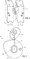
- FIG. 1 illustrates a magnetic drill press 10 including a drill unit 14, a main housing 18 to support the drill unit 14, and a magnetic base 22 coupled to the main housing 18 and selectively magnetically latching the magnetic drill press 10 to a ferromagnetic workpiece (not shown).
- the drill unit 14 may include a DC motor or an AC motor to rotate a spindle with a working tool 26 attached thereto about a rotational axis 28.
- the drill unit 14 is supported by the main housing 18 for relative movement therewith in a direction along the rotational axis 28.
- the magnetic drill press 10 may be powered by a battery 30 as shown in the illustrated embodiment, from an AC voltage input (i.e., from a wall outlet), or by an alternative DC voltage input (e.g., a DC power supply).
- the magnetic base 22 includes a magnet holder 34, a fixed magnet assembly 38 supported within the magnet holder 34, and a rotatable magnet assembly 42 supported within the magnet holder 34 and spaced from the fixed magnet assembly 38.
- the magnet assembly 42 is rotatable with respect to the fixed magnet assembly 38, but in alternative embodiments the magnet assembly 42 may be movable with respect to the fixed magnet assembly 38 in other ways (e.g., translation, rotation and translation, etc.).
- the magnet holder 34 includes bores 63 in which to receive and store fasteners 64, the use of which is explained in further detail below.
- the magnet holder 34 is shown with the rotatable magnet assembly 42 and the fixed magnet assembly 38 removed to better illustrate the geometry of the magnet holder 34.
- the magnet holder 34 in the illustrated embodiment includes ridges 66 and grooves 67 defined between adjacent ridges 66 formed on a bottom surface 70 (i.e., the surface that engages the ferromagnetic workpiece).
- the magnet holder 34 includes four ridges 66 and two grooves 67, the importance of which is described in greater detail below.
- the magnet holder 34 includes slots 74 formed between the rotatable magnet assembly 42 and the fixed magnet assembly 38.
- the magnetic base 22 further includes a transmission 78 having an input 82, an output 86, and a plurality of transmission elements (e.g., a gear train 90) positioned between the output 86 and the input 82.
- the gear train 90 is configured to provide a variable mechanical advantage (e.g., a variable gear ratio) between the output 86 and the input 82.
- the transmission 78 also includes a cover 94 enclosing the gear train 90 and having an aperture 98 through which the input 82 extends.
- a hexagonal body 102 and input knob 104 are coupled for co-rotation with the transmission input 82, and the input knob 104 is accessible to the user of the magnetic drill press 10 for actuating the transmission 78. The user can apply torque to the transmission input 82 using the input knob 104.
- the input 82 and the first gear 106 are rotatably supported (e.g., by one or more bearings) by a support block 122 secured to the magnet holder 34, and the first gear 106 is operable to rotate about a first, non-central axis 126 when an input torque is applied by the user to the knob 104 and the transmission input 82.
- the second gear 110 rotates about a second axis 130 parallel to the first axis 126.
- the second axis 130 may be skewed or perpendicular to the first axis 126.
- a stop pin 134 extends from the second gear 110 at a location offset from the second axis 130.
- the stop pin 134 is received in an arcuate track 138 to limit the rotation of the second gear 110, and therefore the transmission output 86 and the rotatable magnet assembly 42, to a predetermined rotation angle (e.g., approximately 135 degrees in the illustrated embodiment).
- the track138 is defined in the gear cover 94 and spans an arc length nominally greater than 135 degrees to permit the second gear 110 to rotate approximately 135 degrees about the second axis 130. Therefore, the second gear 110 is limited to a predetermined rotation angle of approximately 135 degrees about the second axis 130.
- the arc length of the track may be different depending upon the predetermined rotation angle of the second gear 110 (e.g., approximately 180 degrees).
- variable gear ratio provided by the first gear 106 and the second gear 110 exhibits an overall, average gear ratio of 2:1 over the entire range of motion. Therefore, the input gear 106 and the input knob 104 are limited to a range of rotation equal to approximately 270 degrees. In other words, in the illustrated embodiment, the second gear 110 rotates 135 degrees from start to finish, which corresponds with the first gear 106 rotating 270 degrees from start to finish.
- the transmission output 86 is operable to rotate the rotatable magnet assembly 42 relative to the fixed magnet assembly 38 through the predetermined rotation angle to actuate the magnetic base 22 between a first configuration (i.e., a latched configuration, FIG. 5A ) in which the base 22 can magnetically latch to a ferromagnetic workpiece, and a second configuration (i.e., a release configuration, FIG. 5B ) in which the base 22 cannot magnetically latch to the ferromagnetic workpiece.
- a first configuration i.e., a latched configuration, FIG. 5A
- a second configuration i.e., a release configuration, FIG. 5B
- the magnetic poles (N, S) of the rotatable magnet assembly 42 are positioned such that the north poles N of the rotatable magnet assembly 42 are diagonally offset from the north poles N of the fixed magnet assembly 38, as shown in FIG. 5B .
- the corresponding south poles S of the rotatable magnet assembly 42 and the fixed magnet assembly 38 are diagonally offset from each other.
- the magnetic fields of the rotatable magnet assembly 42 and the fixed magnet assembly 38 are mostly contained within the magnet holder 34 (i.e., almost none of the magnetic field flows through the workpiece, but rather is short-circuited within the magnet holder 34).
- the magnetic base 22 With the magnetic base 22 in the release configuration, the user is able to position the magnetic drill press 10 with respect to the ferromagnetic workpiece in preparation for a drilling operation.
- the magnetic base 22 is actuated from the release configuration ( FIG. 5B ) to the latched configuration ( FIG. 5A ).
- the latched configuration In the latched configuration, the north and south poles N, S of the rotatable magnet assembly 42 and the fixed magnet assembly 38, respectively, are oriented in the same direction (i.e., the north poles N of both the rotatable magnet assembly 42 and the fixed magnet assembly 38 are on the same side of the base 22).
- the magnetic fields of the rotatable magnet assembly 42 and the fixed magnet assembly 38 are directed externally of the magnet holder 34 and into the ferromagnetic workpiece.
- lines of magnetic flux 140 are illustrated with the magnetic base 22 in the latched configuration.
- the grooves 67 i.e., the absence of magnetic material
- Including the grooves 67 on the bottom surface 70 thereby provide high magnetic flux density with controlled saturation in the ridges 66 to increase the holding force, in comparison to a similar magnetic base in which the bottom surface 70 is entirely flat.
- the holding force is increased for relatively thin workpieces by including the grooves 67.
- the holding force is illustrated as a function of the workpiece thickness for the magnetic base 22 with grooves 67, and a similar magnetic base but without any grooves.
- the holding force for the magnetic base 22 with grooves 67 is larger than the magnetic base without any grooves.
- the ridges 66, the grooves 67, and the slots 74 formed in the magnet holder 34 adjust the magnetic characteristics (i.e., magnetic saturation) of the magnetic base 22 to improve the holding force between the magnetic base 22 and relatively thin ferromagnetic workpieces.
- the drill unit 14 can be utilized, for example, to drill through the ferromagnetic workpiece.
- Magnets exhibit repulsion when like poles (i.e., both north poles, or both south poles) face each other and the strength of the repulsion depends on the distance between the like poles. Changing the position of a first magnet with respect to a second magnet will also change the repulsion created as the first magnet is moved from one position to another.
- the repulsion between like poles of the rotatable magnet assembly 42 and the fixed magnet assembly 38 impart a reaction torque or "magnet torque" on the transmission output 86 as the rotatable magnet assembly 42 is rotated between the release configuration and the latched configuration.
- the magnet torque is loaded on the transmission output 86, and the load is reflected through the transmission 78 to the transmission input 82 and the input knob 104.
- the magnet torque is illustrated as a function of the degree of rotation of the rotatable magnet assembly 42.
- FIG. 9 illustrates a range of rotation angle of 135 degrees for the rotatable magnet assembly 42, and a range of rotation angle of 270 degrees for the input knob 104.
- the magnet torque is variable over the 135 degree range of rotation angle.
- the spike in magnet torque followed by the decrease in the magnitude of the magnet torque at approximately 70 degrees is a result of the geometric design and magnetic characteristics of the magnetic base 22.
- the magnet torque if not accounted for in the manner described below of the invention, can cause the user to have to apply a large amount of torque, possibly exceeding human capabilities, to rotate the rotatable magnet assembly 42 between the release configuration and the latched configuration.
- FIG. 8C illustrates the magnetic base 22 in the release configuration with the north poles N poles of the rotatable magnet assembly 42 diagonally offset from the north poles N of the fixed magnet assembly 38.
- the magnetic fields from the rotatable magnet assembly 42 and the fixed magnet assembly 38 are mostly contained within the magnet holder 34; therefore, any holding force generated by the magnetic base 22 while in this configuration is insufficient to latch the base 22 to a ferromagnetic workpiece.
- FIG. 8B illustrates the magnetic base 22 in a transitional configuration between the release and the latched configuration, with the rotatable magnet assembly 42 rotated approximately 45 degrees.
- FIG. 8A illustrates the magnetic base 22 in the latched configuration with the second gear 110 having traveled the predetermined rotation angle (i.e., about 135 degrees) and the first gear 106 having traveled the predetermined rotation angle (i.e., about 270 degrees).
- variable gear ratio of the gear train 90 is illustrated as a function of the predetermined rotational angle of approximately 135 degrees (i.e., the rotational span of the rotatable magnet assembly 42).
- the gear ratio is designed to provide a larger mechanical advantage (i.e., a large gear ratio) when the magnet torque is large, and to provide a smaller mechanical advantage (i.e., a small gear ratio) when the magnet torque is small.
- the meshed gears 106, 110 form a line of contact 142 between the rotational axes 126, 130 of the gears, and the radius of each of the gears 106, 110 continuously changes during rotation.
- the gear ratio is the smallest when the first gear 106 radius R1 along the line of contact 142 is the largest and the second gear 110 radius R2 along the line of contact 142 is the smallest.
- the gear ratio is the largest when the first gear 106 radius R1 along the line of contact 142 is the smallest and the second gear 110 radius R2 along the line of contact 142 is the largest.
- the gear train 90 is configured to apply a variable output torque to the rotatable magnet assembly 42 through at least a portion of the predetermined rotation angle of the rotatable magnet assembly 42.
- the variable gear ratio generally increases when the magnet torque increases, and generally decreases when the magnet torque decreases.
- the transmission 78 creates an improved feel for the user as the magnetic base 22 is switched between the latched configuration and the release configuration.
- prior art magnetic bases required a spike in input torque by the user to account for the non-linear magnet torque. This spike in required input torque creates an unstable feel for the user and can exceed the user's physical ability.
- the magnetic base 22 of the invention eliminates these problems by making the input torque applied by the user generally constant throughout a substantial range of rotation angle of the rotatable magnet assembly 42, thereby eliminating any spikes in required input torque and keeping the applied input torque within a user's physical ability.
- the required input torque kept within a user's physical ability with the transmission 78, but the amount of required input rotation is also reduced.
- the transmission input 82 can be rotated by an amount that is independent (i.e., different) than that of the transmission output 86 for actuating the magnetic base 22 between the latched and release configurations (i.e., the transmission input 82 can be rotated more or less than the required transmission output 86 rotation).
- the knob 104 and transmission input 82 can be rotated about 180 degrees to actuate the magnetic base 22 between the latched and release configurations.
- a motor can be included to switch the magnetic base between the release configuration and the latched configuration instead of requiring user input torque and rotation.
- the motor can be advantageously selected to be efficient and small as a result of the variable mechanical advantage provided by the transmission 78.
- the motor needs only to be designed to handle a uniform load profile (i.e., a relatively constant torque), the design specifications for the motor become simplified.
- the transmission input 82 is rotated clockwise (as viewed from FIG. 8C ) to switch the magnetic base 22 from the release configuration to the latched configuration.
- the gear train 90 may be configured such that the transmission input 82 is rotated counter-clockwise to switch the magnetic base 22 from the release configuration to the latched configuration.
- the variable gear ratio could be designed to exactly match the variable magnet torque, resulting in an input torque held within a band of 1 N-m or less across a substantial portion of rotation angle of the rotatable magnet assembly 42.
- the transmission can be customized to provide any user experience regarding the required input torque (i.e., gradually increasing input torque, gradually decreasing input torque, oscillating input torque, etc.).
- the transmission could include any number and configuration of transmission elements (e.g., linkages, gears, cams, etc.) that provide a variable mechanical advantage between the transmission input 82 and the transmission output 86.
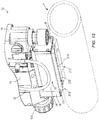
- the drill press 10 may also include an adapter 200.
- an adapter 200 In some applications, it is desired to use the magnetic drill press 10 on a non-flat, or curved, surface (e.g., a pipe P).
- the adapter 200 is removably coupled to the magnet holder 34 to facilitate placement of the magnet holder 34 on a curved ferromagnetic workpiece.
- the adapter 200 includes a plurality of projections 204 received within the corresponding grooves 67 in the magnet holder 34 ( FIG. 13 ).
- the adapter 200 is secured to the magnet holder 34 with the fasteners 64 which, in turn, are threaded within the bores 63.
- the adapter 200 includes a first side portion 208 and a second side portion 212, and each of the side portions 208, 212 includes a curved surface 218 that is engageable with the curved ferromagnetic workpiece.
- a window 222 is defined between the first side portion 208 and the second side portion 212.
- the window 222 is unobstructed; however, alternative embodiments may include non-ferromagnetic material within the window.
- the fasteners 64 may be stored within the bores 63 in the magnet holder 34 until the adapter 200 is attached again.
- the curved surfaces 218 provide at least two points of contact on which to support the magnet holder 34 on workpieces having a variety of curvature. In other words, the curved surfaces 218 allow the magnet holder 34 to be supported on a range of pipe diameters, for example.
- the adapter may include a non-metal (e.g., plastic) frame and a plurality of ferromagnetic blocks secured together by the frame. The blocks may further include a curved surface that is engageable with the curved ferromagnetic workpiece.
Landscapes
- Engineering & Computer Science (AREA)
- Mechanical Engineering (AREA)
- Drilling And Boring (AREA)
- Dynamo-Electric Clutches, Dynamo-Electric Brakes (AREA)
Claims (6)
- Magnetische Ständerbohrmaschine (10), die Folgendes umfasst:ein Hauptgehäuse (18),eine Bohreinheit (14), die durch das Hauptgehäuse getragen wird, für eine relative Bewegung mit demselben in einer Richtung einer Drehachse (28) der Bohreinheit, undeine Basis (22), die mit dem Hauptgehäuse verbunden ist, zum selektiven magnetischen Verriegeln mit einem ferromagnetischen Werkstück, wobei die Basis Folgendes einschließt:eine Magnethalterung (34),eine unbewegliche Magnetbaugruppe (38), die innerhalb der Magnethalterung getragen wird,eine drehbare Magnetbaugruppe (42), die innerhalb der Magnethalterung getragen wird, undein Getriebe (78), das Folgendes einschließt:einen Antrieb (82),einen Abtrieb (86), der mit der drehbaren Magnetbaugruppe verbunden ist, zum Drehen der drehbaren Magnetbaugruppe im Verhältnis zu der unbeweglichen Magnetbaugruppe durch einen vorbestimmten Drehungswinkel, undeinen Getriebezug (90), der zwischen dem Abtrieb und dem Antrieb angeordnet ist, wobei der Getriebezug dafür konfiguriert ist, ein veränderliches Übersetzungsverhältnis zwischen dem Abtrieb und dem Antrieb während wenigstens eines Abschnitts des vorbestimmten Drehungswinkels bereitzustellen.
- Magnetische Ständerbohrmaschine (10) nach Anspruch 1, wobei:die drehbare Magnetbaugruppe (42) um etwa 135 Grad im Verhältnis zu der unbeweglichen Magnetbaugruppe (38) gedreht wird, um die magnetische Basis (22) zu betätigen, zwischen einer ersten Konfiguration, in der sich die Basis magnetisch mit einem ferromagnetischen Werkstück verriegeln kann, und einer zweiten Konfiguration, in der sich die Basis nicht magnetisch mit dem ferromagnetischen Werkstück verriegeln kann, und/oderdie Magnethalterung (34) einen Schlitz (74) zwischen der drehbaren Magnetbaugruppe und der unbeweglichen Magnetbaugruppe einschließt,wobei wahlweise der Getriebeantrieb (82) um etwa 270 Grad gedreht wird, um die magnetische Basis zwischen der ersten und der zweiten Konfiguration zu betätigen.
- Magnetische Ständerbohrmaschine (10) nach Anspruch 1, wobei die Magnethalterung (34) Stege (66) auf einer Oberfläche (70) der Magnethalterung einschließt, die mit dem ferromagnetischen Werkstück in Eingriff gebracht werden können.
- Magnetische Ständerbohrmaschine (10) nach Anspruch 3, wobei die Magnethalterung (34) eine Rille (67) einschließt, die zwischen benachbarten Stegen (66) definiert wird, und wobei wahlweise die Rille eine erste von mehreren Rillen ist.
- Magnetische Ständerbohrmaschine (10) nach Anspruch 4, die ferner einen Adapter (200) umfasst, der mit der Magnethalterung (34) verbunden ist, um ein Platzieren der Magnethalterung auf einem gekrümmten ferromagnetischen Werkstück zu erleichtern.
- Magnetische Ständerbohrmaschine (10) nach Anspruch 5, wobei:der Adapter (200) mehrere Vorsprünge (204) einschließt, die innerhalb der entsprechenden mehreren Rillen (67) in der Magnethalterung (34) aufgenommen werden, und/oderder Adapter einen ersten Seitenabschnitt (208) und einen zweiten Seitenabschnitt (212) einschließt und wobei sowohl der erste als auch der zweite Seitenabschnitt eine gekrümmte Oberfläche (218) einschließt, die mit dem gekrümmten ferromagnetischen Werkstück in Eingriff gebracht werden kann, und/oderder Adapter mit einem Befestigungselement (64) an der Magnethalterung befestigt ist und/oderder Adapter ein Fenster (222) einschließt, das zwischen dem ersten Seitenabschnitt und dem zweiten Seitenabschnitt definiert wird.
Priority Applications (2)
| Application Number | Priority Date | Filing Date | Title |
|---|---|---|---|
| EP19201771.3A EP3613526B1 (de) | 2013-04-19 | 2014-04-18 | Magnetischer bohrständer |
| EP19201775.4A EP3632599B1 (de) | 2013-04-19 | 2014-04-18 | Magnetische haltevorrichtung |
Applications Claiming Priority (3)
| Application Number | Priority Date | Filing Date | Title |
|---|---|---|---|
| US201361813813P | 2013-04-19 | 2013-04-19 | |
| US201361898790P | 2013-11-01 | 2013-11-01 | |
| PCT/US2014/034627 WO2014172620A1 (en) | 2013-04-19 | 2014-04-18 | Magnetic drill press |
Related Child Applications (2)
| Application Number | Title | Priority Date | Filing Date |
|---|---|---|---|
| EP19201775.4A Division EP3632599B1 (de) | 2013-04-19 | 2014-04-18 | Magnetische haltevorrichtung |
| EP19201771.3A Division EP3613526B1 (de) | 2013-04-19 | 2014-04-18 | Magnetischer bohrständer |
Publications (3)
| Publication Number | Publication Date |
|---|---|
| EP2986408A1 EP2986408A1 (de) | 2016-02-24 |
| EP2986408A4 EP2986408A4 (de) | 2017-03-15 |
| EP2986408B1 true EP2986408B1 (de) | 2019-10-09 |
Family
ID=51729129
Family Applications (3)
| Application Number | Title | Priority Date | Filing Date |
|---|---|---|---|
| EP19201771.3A Active EP3613526B1 (de) | 2013-04-19 | 2014-04-18 | Magnetischer bohrständer |
| EP14785292.5A Active EP2986408B1 (de) | 2013-04-19 | 2014-04-18 | Magnetischer bohrständer |
| EP19201775.4A Active EP3632599B1 (de) | 2013-04-19 | 2014-04-18 | Magnetische haltevorrichtung |
Family Applications Before (1)
| Application Number | Title | Priority Date | Filing Date |
|---|---|---|---|
| EP19201771.3A Active EP3613526B1 (de) | 2013-04-19 | 2014-04-18 | Magnetischer bohrständer |
Family Applications After (1)
| Application Number | Title | Priority Date | Filing Date |
|---|---|---|---|
| EP19201775.4A Active EP3632599B1 (de) | 2013-04-19 | 2014-04-18 | Magnetische haltevorrichtung |
Country Status (4)
| Country | Link |
|---|---|
| US (3) | US9242367B2 (de) |
| EP (3) | EP3613526B1 (de) |
| CN (2) | CN205218121U (de) |
| WO (1) | WO2014172620A1 (de) |
Families Citing this family (28)
| Publication number | Priority date | Publication date | Assignee | Title |
|---|---|---|---|---|
| US9434039B2 (en) * | 2012-05-16 | 2016-09-06 | C. & E. Fein Gmbh | Drill press with an adjustable gib |
| BR112015009581A2 (pt) * | 2012-10-31 | 2017-07-04 | Husqvarna Ab | espaçador para afastamento de uma ferramenta de um suporte de ferramenta. |
| US9669539B2 (en) | 2014-03-21 | 2017-06-06 | The United States Of America As Represented By The Secretary Of The Navy | Magnetic drill system |
| EP3234732B1 (de) * | 2014-12-19 | 2021-11-24 | Hewlett-Packard Development Company, L.P. | Interaktion mit 3d-visualisierung |
| US10903030B2 (en) | 2017-04-27 | 2021-01-26 | Magswitch Technology Worldwide Pty Ltd. | Variable field magnetic couplers and methods for engaging a ferromagnetic workpiece |
| US11097401B2 (en) | 2017-04-27 | 2021-08-24 | Magswitch Technology Worldwide Pty Ltd. | Magnetic coupling device with at least one of a sensor arrangement and a degauss capability |
| US12023770B2 (en) | 2017-04-27 | 2024-07-02 | Magswitch Technology, Inc. | Magnetic coupling device with at least one of a sensor arrangement and a degauss capability |
| US20250065460A1 (en) * | 2017-04-27 | 2025-02-27 | Magswitch Technology, Inc. | Magnetic coupling device with at least one of a sensor arrangement and a degauss capability |
| KR102313077B1 (ko) | 2017-06-08 | 2021-10-14 | 마그스위치 테크놀러지 월드 와이드 피티와이 리미티드 | 전자석 전환 가능 영구 자석 디바이스 |
| US11915864B2 (en) * | 2018-01-11 | 2024-02-27 | Berndorf Band Gmbh | Magnetic retaining device |
| ES2964415T3 (es) * | 2018-01-29 | 2024-04-05 | Magswitch Tech Inc | Dispositivo de elevación magnético que tiene zapatas de polos con proyecciones espaciadas |
| US10953534B2 (en) * | 2018-06-29 | 2021-03-23 | Trevor John DONALDSON | Apparatus and system for magnetic stabilization of handheld power tools |
| CN108788245B (zh) * | 2018-09-05 | 2024-02-06 | 南通承悦装饰集团有限公司 | 一种多面吸力轻便式组合型直流磁座钻 |
| WO2020086791A1 (en) | 2018-10-24 | 2020-04-30 | Magswitch Technology Worldwide Pty Ltd. | Linearly actuated magnetic coupling device |
| DE202019102790U1 (de) * | 2019-05-16 | 2020-08-18 | C. & E. Fein Gmbh | Magnetfuß |
| DE202019103844U1 (de) * | 2019-07-12 | 2020-10-15 | C. & E. Fein Gmbh | Magnetfuß und Elektrowerkzeugmaschine |
| DE202019106916U1 (de) | 2019-12-12 | 2021-03-15 | C. & E. Fein Gmbh | Magnetfuß |
| WO2021237356A1 (en) * | 2020-05-27 | 2021-12-02 | Grinder Grip Inc. | Magnetic cassette for power tool mounts |
| CN112140243A (zh) * | 2020-09-25 | 2020-12-29 | 李爱晓 | 一种磁吸原理定位的办公家具用板材打孔设备 |
| EP4274702A4 (de) | 2021-01-11 | 2025-03-12 | Black & Decker Inc. | Magnetische bohrpresse |
| CN115210039A (zh) * | 2021-02-02 | 2022-10-18 | 株式会社晧山技术 | 磁力座及包括其的磁力钻 |
| WO2022168997A1 (ko) * | 2021-02-02 | 2022-08-11 | 주식회사 호산기술 | 자기 홀더 및 이를 포함하는 마그네틱 드릴 |
| EP4341049A4 (de) | 2021-06-11 | 2025-03-12 | Magswitch Technology, Inc. | Werkzeug oder vorrichtung mit einstellbarem armende |
| GB2610576A (en) | 2021-09-08 | 2023-03-15 | Black & Decker Inc | A power tool stand |
| GB2610578B (en) | 2021-09-08 | 2025-03-26 | Black & Decker Inc | A power tool stand |
| EP4289562A1 (de) * | 2022-06-07 | 2023-12-13 | Hilti Aktiengesellschaft | Werkzeugmaschine mit parallelen abtriebs- und motorachsen |
| CN115014609A (zh) * | 2022-06-07 | 2022-09-06 | 中铁检验认证中心有限公司 | 用于车轴残余应力检测的试验平台及使用方法 |
| GB2629148A (en) * | 2023-04-17 | 2024-10-23 | Troika Systems Ltd | Magnetic support for microscopic surface inspection system |
Family Cites Families (73)
| Publication number | Priority date | Publication date | Assignee | Title |
|---|---|---|---|---|
| US2209558A (en) | 1937-04-22 | 1940-07-30 | Karl Otto Goettsch | Magnetic clamping appliance |
| US2217048A (en) * | 1937-11-26 | 1940-10-08 | Robbins Engineering Company | Magnetic work holder |
| US2280437A (en) | 1939-11-02 | 1942-04-21 | Brown & Sharpe Mfg | Releasable permanent magnet holding device |
| USRE24203E (en) | 1952-05-10 | 1956-08-28 | Electromagnetic drill unit | |
| US2820377A (en) | 1954-06-01 | 1958-01-21 | Buck Mfg Co | Portable magnetic drill press |
| US3017545A (en) * | 1954-08-12 | 1962-01-16 | Alfred E Herzer | Device for magnetic clamping |
| DE1096795B (de) * | 1955-03-07 | 1961-01-05 | Wilhelm Donaubauer | Auf eine magnetische Aufspannplatte aufsetzbare Haltevorrichtung zum Bearbeiten keilfoermiger Werkstuecke, z.B. Keilleisten |
| US3010054A (en) * | 1958-04-24 | 1961-11-21 | Hagou Metaalfab N V | Permanent magnetic chuck |
| US3342089A (en) | 1965-08-31 | 1967-09-19 | Buck Mfg Company | Magnetic drill mount with base magnet having enlarged outer pole areas |
| US3387509A (en) * | 1965-09-20 | 1968-06-11 | George J. Lupear | Work tool fixture |
| US3452310A (en) | 1966-11-14 | 1969-06-24 | Eriez Mfg Co | Turn-off permanent magnet |
| US3540320A (en) | 1968-06-13 | 1970-11-17 | Werner W Martinmaas | Portable drill press apparatus |
| US3677656A (en) | 1971-02-19 | 1972-07-18 | Eugene W Buck | Radial positioner, lock and rotary contacts for electromagnetic drill mount |
| JPS5420714B2 (de) * | 1971-08-25 | 1979-07-25 | ||
| US3762829A (en) | 1971-10-20 | 1973-10-02 | M Yilmaz | Adjustable tool guide and support |
| US4012162A (en) * | 1975-02-10 | 1977-03-15 | Warren Wesley S | All purpose magnetic base drill |
| DE2517364A1 (de) | 1975-04-19 | 1976-10-28 | Max Baermann | Schaltbare, dauermagnetische haltevorrichtung |
| US4094612A (en) | 1976-07-29 | 1978-06-13 | Widder Corporation | Tool mounting apparatus |
| JPS5578505A (en) | 1978-12-08 | 1980-06-13 | Kanetsuu Kogyo Kk | Attraction type magnetic device |
| US4261673A (en) | 1979-04-05 | 1981-04-14 | Hougen Everett D | Magnetic base drill |
| JPS5626415A (en) | 1979-08-12 | 1981-03-14 | Kanetsuu Kogyo Kk | Magnetic device for attraction |
| FR2464125A1 (fr) * | 1979-08-27 | 1981-03-06 | Braillon P | Bloc magnetique a aimants permanents et a dispositif mecanique de commande marche-arret |
| USRE30519E (en) | 1979-11-15 | 1981-02-17 | Accessory support plates for a magnet base drill | |
| US4390309A (en) | 1981-05-11 | 1983-06-28 | Jancy Engineering Co. | Cradle pipe adaptor for magnetic drill |
| US4393363A (en) | 1981-05-18 | 1983-07-12 | Fuju Jiko Kabushiki Kaisha | Magnet base for tool |
| FR2523940A1 (fr) * | 1982-03-25 | 1983-09-30 | Braillon Cie | Appareil magnetique, notamment pour la manutention |
| US4639170A (en) | 1985-04-08 | 1987-01-27 | Milwaukee Electric Tool Corporation | Magnetic base for portable tools |
| US4892447A (en) | 1988-02-08 | 1990-01-09 | Everett D. Hougen | Torque restraining device for drill with self-attaching base |
| US4936720A (en) | 1989-09-26 | 1990-06-26 | Fend Industrial Tool Inc. | Compact device for cutting holes in pipe |
| JP2510451Y2 (ja) | 1990-01-26 | 1996-09-11 | 日東工器 株式会社 | 電磁石ベ―ス付ドリル装置 |
| US5051044A (en) | 1990-03-05 | 1991-09-24 | Harold Allen | Pipe drilling apparatus |
| GB2264004B (en) | 1992-01-29 | 1995-08-09 | Eclipse Magnetics Limited | A magnetic support for a machine tool |
| US5266914A (en) | 1992-06-15 | 1993-11-30 | The Herman Schmidt Company | Magnetic chuck assembly |
| US5462392A (en) | 1994-07-21 | 1995-10-31 | Hardwick; Austin | Magnetically attachable, portable, adjustable, and collapsible safe drilling mount for steel safes |
| US5525950A (en) | 1995-08-11 | 1996-06-11 | Wang; Chin-Yuan | Magnetic base |
| GB9621472D0 (en) | 1996-10-15 | 1996-12-04 | Turner Gordon H | Non-magnetic clamping system for drilling pipes for branch tees |
| US5848859A (en) | 1997-01-08 | 1998-12-15 | The Boeing Company | Self normalizing drill head |
| AUPQ446699A0 (en) | 1999-12-06 | 2000-01-06 | Kocijan, Franz | Switchable (variable) permanent magnet device |
| US6489871B1 (en) | 1999-12-11 | 2002-12-03 | Simon C. Barton | Magnetic workholding device |
| US6331810B1 (en) | 2000-09-01 | 2001-12-18 | Hyung Jung | Magnetic lifting apparatus |
| US6994305B2 (en) | 2001-04-07 | 2006-02-07 | Robertshaw Controls Company | Magnetic mounting assembly |
| JP2002254227A (ja) | 2001-03-02 | 2002-09-10 | Hitachi Koki Co Ltd | 磁気ボール盤のセンタ決め機構 |
| EP1453641A1 (de) | 2001-07-26 | 2004-09-08 | Gordon Henry Turner | Vorrichtung zur befestigung eines bohrers auf einer röhre |
| GB2379405A (en) | 2001-07-26 | 2003-03-12 | Gordon Henry Turner | Detachable extension apparatus for a frame for mounting a drill on a pipe |
| US7009480B2 (en) | 2001-11-08 | 2006-03-07 | Valtra, Inc. | Semi-releasable magnetic tool |
| US7369916B2 (en) | 2002-04-18 | 2008-05-06 | Black & Decker Inc. | Drill press |
| JP2004009149A (ja) | 2002-06-03 | 2004-01-15 | Osada Res Inst Ltd | 位置決め用光源を有する工作機械 |
| GB2404161B (en) | 2003-07-14 | 2007-01-03 | Gordon Henry Turner | Apparatus for mounting a drill on a pipe |
| US7224251B2 (en) | 2004-07-16 | 2007-05-29 | Earth-Chain Enterprise Co., Ltd. | Magnetic retaining device for machine tool |
| CN101035650B (zh) * | 2004-08-24 | 2010-05-26 | Srb建筑技术有限公司 | 磁性夹具 |
| US7161451B2 (en) | 2005-04-14 | 2007-01-09 | Gm Global Technology Operations, Inc. | Modular permanent magnet chuck |
| WO2007119245A1 (en) * | 2005-04-25 | 2007-10-25 | East Coast Enterprisers Limited | Magnetic and mechanical work holding apparatus with monolithic working face |
| DE102005021094A1 (de) | 2005-05-06 | 2006-11-09 | B.T. Innovation Gmbh | Schaltbare Magnetvorrichtung |
| US7435041B1 (en) | 2005-07-19 | 2008-10-14 | Mcgill Ronald L | Hole cutting assembly for pipes and well casings |
| EP1941521A4 (de) | 2005-09-26 | 2011-06-15 | Magswitch Technology Worldwide Pty Ltd | Magnet-arrays |
| US7936142B2 (en) | 2005-12-26 | 2011-05-03 | Nitto Kohki Co., Ltd. | Portable drilling device |
| US8272813B1 (en) | 2006-01-30 | 2012-09-25 | Wise Robert W | Combination power tool and object sensor |
| US7396194B2 (en) | 2006-02-13 | 2008-07-08 | Washington Suburban Sanitary Commission | Adjustable clamping arrangement for magnetic mounting plate |
| US7549359B2 (en) | 2007-06-11 | 2009-06-23 | Gas Technology Institute | Aldyl a tee scraper |
| US8376667B2 (en) | 2007-07-27 | 2013-02-19 | Milwaukee Electric Tool Corporation | AC/DC magnetic drill press |
| DE102007058188A1 (de) | 2007-12-04 | 2009-06-10 | Fidlock Gmbh | Magnetische Kopplungsvorrichtung |
| WO2010020006A1 (en) | 2008-08-20 | 2010-02-25 | Magswitch Technology (Worldwide) Pty Ltd | Magnetic woodworking base and resaw fence |
| GB0815766D0 (en) * | 2008-08-29 | 2008-10-08 | Lontra Ltd | Rotary piston and cylinder devices |
| WO2010135788A1 (en) | 2009-05-29 | 2010-12-02 | Magswitch Technology Worldwide Pty Ltd | Switchable magnetic implement |
| US8183965B2 (en) | 2010-04-09 | 2012-05-22 | Creative Engineering Solutions, Inc. | Switchable core element-based permanent magnet apparatus |
| DE102010029681B4 (de) * | 2010-06-02 | 2013-12-24 | Horst Flaig | Magnetische Haltevorrichtung |
| US20120141217A1 (en) * | 2010-12-05 | 2012-06-07 | Black & Decker Inc. | Zeroable depth scale for drill presses and methods therefor |
| KR20120119412A (ko) | 2011-04-21 | 2012-10-31 | 최태광 | 영구자석 워크홀딩 장치 |
| US20130002382A1 (en) | 2011-06-28 | 2013-01-03 | Bo Zhang | Magnetic cup assembly holding device with low magnetic leakage field |
| KR20130020403A (ko) * | 2011-08-19 | 2013-02-27 | 에스티엑스조선해양 주식회사 | 보조 흡착수단이 구비된 마그네틱 드릴 장치 |
| US8350663B1 (en) | 2011-12-07 | 2013-01-08 | Creative Engineering Solutions, Inc. | Rotary switchable multi-core element permanent magnet-based apparatus |
| US20130287508A1 (en) | 2012-04-25 | 2013-10-31 | Milwaukee Electric Tool Corporation | Magnetic drill press |
| US9561568B2 (en) * | 2014-04-25 | 2017-02-07 | Black & Decker Inc. | Magnetic drill press with alternate power source |
-
2014
- 2014-04-18 US US14/256,255 patent/US9242367B2/en active Active
- 2014-04-18 WO PCT/US2014/034627 patent/WO2014172620A1/en not_active Ceased
- 2014-04-18 EP EP19201771.3A patent/EP3613526B1/de active Active
- 2014-04-18 EP EP14785292.5A patent/EP2986408B1/de active Active
- 2014-04-18 EP EP19201775.4A patent/EP3632599B1/de active Active
- 2014-04-18 CN CN201490000596.9U patent/CN205218121U/zh not_active Expired - Fee Related
- 2014-04-18 CN CN201620117105.XU patent/CN205496630U/zh not_active Expired - Fee Related
-
2015
- 2015-09-16 US US14/856,073 patent/US9452522B2/en active Active
- 2015-09-16 US US14/855,908 patent/US9452521B2/en active Active
Non-Patent Citations (1)
| Title |
|---|
| None * |
Also Published As
| Publication number | Publication date |
|---|---|
| US9242367B2 (en) | 2016-01-26 |
| EP3632599A1 (de) | 2020-04-08 |
| US20160001439A1 (en) | 2016-01-07 |
| EP3613526A1 (de) | 2020-02-26 |
| WO2014172620A1 (en) | 2014-10-23 |
| US9452522B2 (en) | 2016-09-27 |
| US20160001440A1 (en) | 2016-01-07 |
| EP3632599B1 (de) | 2023-08-02 |
| CN205496630U (zh) | 2016-08-24 |
| EP2986408A4 (de) | 2017-03-15 |
| US20140314507A1 (en) | 2014-10-23 |
| US9452521B2 (en) | 2016-09-27 |
| CN205218121U (zh) | 2016-05-11 |
| EP2986408A1 (de) | 2016-02-24 |
| EP3613526B1 (de) | 2023-12-13 |
Similar Documents
| Publication | Publication Date | Title |
|---|---|---|
| EP2986408B1 (de) | Magnetischer bohrständer | |
| CN103501965B (zh) | 动力工具的正转/反转切换装置 | |
| US20140008090A1 (en) | Handheld Power Tools with Triggers and Methods for Assembling Same | |
| US20030094356A1 (en) | Switch mechanism for a power tool | |
| US7172500B1 (en) | Knife sharpener | |
| US20110315413A1 (en) | Kit-Of Parts for Multi-Functional Tool, Drive Unit, and Operating Members | |
| CN103796804B (zh) | 马达式运行的工具机 | |
| US20150097641A1 (en) | Switch assembly for electric tool | |
| EP3533564B1 (de) | Elektrowerkzeug | |
| US20030015066A1 (en) | Positionable power screwdriver | |
| US10232449B2 (en) | Combination tool | |
| US20040226411A1 (en) | Wrench structure having a driving mechanism | |
| US11279019B2 (en) | Magnetic base | |
| CN103534067A (zh) | 具有触发器的手持式电动工具及其组装方法 | |
| CN101163570B (zh) | 用于打磨机的打磨垫锁定件 | |
| US7240591B2 (en) | Adjustable spanner | |
| CN102581376A (zh) | 往复切割工具 | |
| US20090146358A1 (en) | Clamp | |
| US20140191458A1 (en) | Fixture block | |
| CN218947625U (zh) | 精密电动螺丝刀工具盒及其套装 | |
| CN104108085A (zh) | 具有手动棘齿机构的电动工具 | |
| CN216338287U (zh) | 基于钉扣车使用的钉扣方向调节装置 | |
| JP2006315119A (ja) | トリガースイッチ及びそれを用いたモータの駆動回路 | |
| GB2441311A (en) | Knife sharpener | |
| KR101512746B1 (ko) | 비트세트 일체형 전동 드라이버 |
Legal Events
| Date | Code | Title | Description |
|---|---|---|---|
| PUAI | Public reference made under article 153(3) epc to a published international application that has entered the european phase |
Free format text: ORIGINAL CODE: 0009012 |
|
| 17P | Request for examination filed |
Effective date: 20151027 |
|
| AK | Designated contracting states |
Kind code of ref document: A1 Designated state(s): AL AT BE BG CH CY CZ DE DK EE ES FI FR GB GR HR HU IE IS IT LI LT LU LV MC MK MT NL NO PL PT RO RS SE SI SK SM TR |
|
| AX | Request for extension of the european patent |
Extension state: BA ME |
|
| DAX | Request for extension of the european patent (deleted) | ||
| A4 | Supplementary search report drawn up and despatched |
Effective date: 20170215 |
|
| RIC1 | Information provided on ipc code assigned before grant |
Ipc: B23B 47/00 20060101ALI20170209BHEP Ipc: B23B 45/14 20060101AFI20170209BHEP |
|
| GRAP | Despatch of communication of intention to grant a patent |
Free format text: ORIGINAL CODE: EPIDOSNIGR1 |
|
| STAA | Information on the status of an ep patent application or granted ep patent |
Free format text: STATUS: GRANT OF PATENT IS INTENDED |
|
| INTG | Intention to grant announced |
Effective date: 20190430 |
|
| GRAS | Grant fee paid |
Free format text: ORIGINAL CODE: EPIDOSNIGR3 |
|
| GRAA | (expected) grant |
Free format text: ORIGINAL CODE: 0009210 |
|
| STAA | Information on the status of an ep patent application or granted ep patent |
Free format text: STATUS: THE PATENT HAS BEEN GRANTED |
|
| AK | Designated contracting states |
Kind code of ref document: B1 Designated state(s): AL AT BE BG CH CY CZ DE DK EE ES FI FR GB GR HR HU IE IS IT LI LT LU LV MC MK MT NL NO PL PT RO RS SE SI SK SM TR |
|
| REG | Reference to a national code |
Ref country code: GB Ref legal event code: FG4D |
|
| REG | Reference to a national code |
Ref country code: CH Ref legal event code: EP |
|
| REG | Reference to a national code |
Ref country code: IE Ref legal event code: FG4D |
|
| REG | Reference to a national code |
Ref country code: DE Ref legal event code: R096 Ref document number: 602014054959 Country of ref document: DE |
|
| REG | Reference to a national code |
Ref country code: AT Ref legal event code: REF Ref document number: 1188197 Country of ref document: AT Kind code of ref document: T Effective date: 20191115 |
|
| REG | Reference to a national code |
Ref country code: NL Ref legal event code: MP Effective date: 20191009 |
|
| REG | Reference to a national code |
Ref country code: LT Ref legal event code: MG4D |
|
| REG | Reference to a national code |
Ref country code: AT Ref legal event code: MK05 Ref document number: 1188197 Country of ref document: AT Kind code of ref document: T Effective date: 20191009 |
|
| PG25 | Lapsed in a contracting state [announced via postgrant information from national office to epo] |
Ref country code: GR Free format text: LAPSE BECAUSE OF FAILURE TO SUBMIT A TRANSLATION OF THE DESCRIPTION OR TO PAY THE FEE WITHIN THE PRESCRIBED TIME-LIMIT Effective date: 20200110 Ref country code: FI Free format text: LAPSE BECAUSE OF FAILURE TO SUBMIT A TRANSLATION OF THE DESCRIPTION OR TO PAY THE FEE WITHIN THE PRESCRIBED TIME-LIMIT Effective date: 20191009 Ref country code: PT Free format text: LAPSE BECAUSE OF FAILURE TO SUBMIT A TRANSLATION OF THE DESCRIPTION OR TO PAY THE FEE WITHIN THE PRESCRIBED TIME-LIMIT Effective date: 20200210 Ref country code: NL Free format text: LAPSE BECAUSE OF FAILURE TO SUBMIT A TRANSLATION OF THE DESCRIPTION OR TO PAY THE FEE WITHIN THE PRESCRIBED TIME-LIMIT Effective date: 20191009 Ref country code: AT Free format text: LAPSE BECAUSE OF FAILURE TO SUBMIT A TRANSLATION OF THE DESCRIPTION OR TO PAY THE FEE WITHIN THE PRESCRIBED TIME-LIMIT Effective date: 20191009 Ref country code: LV Free format text: LAPSE BECAUSE OF FAILURE TO SUBMIT A TRANSLATION OF THE DESCRIPTION OR TO PAY THE FEE WITHIN THE PRESCRIBED TIME-LIMIT Effective date: 20191009 Ref country code: SE Free format text: LAPSE BECAUSE OF FAILURE TO SUBMIT A TRANSLATION OF THE DESCRIPTION OR TO PAY THE FEE WITHIN THE PRESCRIBED TIME-LIMIT Effective date: 20191009 Ref country code: LT Free format text: LAPSE BECAUSE OF FAILURE TO SUBMIT A TRANSLATION OF THE DESCRIPTION OR TO PAY THE FEE WITHIN THE PRESCRIBED TIME-LIMIT Effective date: 20191009 Ref country code: ES Free format text: LAPSE BECAUSE OF FAILURE TO SUBMIT A TRANSLATION OF THE DESCRIPTION OR TO PAY THE FEE WITHIN THE PRESCRIBED TIME-LIMIT Effective date: 20191009 Ref country code: BG Free format text: LAPSE BECAUSE OF FAILURE TO SUBMIT A TRANSLATION OF THE DESCRIPTION OR TO PAY THE FEE WITHIN THE PRESCRIBED TIME-LIMIT Effective date: 20200109 Ref country code: NO Free format text: LAPSE BECAUSE OF FAILURE TO SUBMIT A TRANSLATION OF THE DESCRIPTION OR TO PAY THE FEE WITHIN THE PRESCRIBED TIME-LIMIT Effective date: 20200109 Ref country code: PL Free format text: LAPSE BECAUSE OF FAILURE TO SUBMIT A TRANSLATION OF THE DESCRIPTION OR TO PAY THE FEE WITHIN THE PRESCRIBED TIME-LIMIT Effective date: 20191009 |
|
| PG25 | Lapsed in a contracting state [announced via postgrant information from national office to epo] |
Ref country code: RS Free format text: LAPSE BECAUSE OF FAILURE TO SUBMIT A TRANSLATION OF THE DESCRIPTION OR TO PAY THE FEE WITHIN THE PRESCRIBED TIME-LIMIT Effective date: 20191009 Ref country code: HR Free format text: LAPSE BECAUSE OF FAILURE TO SUBMIT A TRANSLATION OF THE DESCRIPTION OR TO PAY THE FEE WITHIN THE PRESCRIBED TIME-LIMIT Effective date: 20191009 Ref country code: IS Free format text: LAPSE BECAUSE OF FAILURE TO SUBMIT A TRANSLATION OF THE DESCRIPTION OR TO PAY THE FEE WITHIN THE PRESCRIBED TIME-LIMIT Effective date: 20200224 |
|
| PG25 | Lapsed in a contracting state [announced via postgrant information from national office to epo] |
Ref country code: AL Free format text: LAPSE BECAUSE OF FAILURE TO SUBMIT A TRANSLATION OF THE DESCRIPTION OR TO PAY THE FEE WITHIN THE PRESCRIBED TIME-LIMIT Effective date: 20191009 |
|
| REG | Reference to a national code |
Ref country code: DE Ref legal event code: R097 Ref document number: 602014054959 Country of ref document: DE |
|
| PG2D | Information on lapse in contracting state deleted |
Ref country code: IS |
|
| PG25 | Lapsed in a contracting state [announced via postgrant information from national office to epo] |
Ref country code: DK Free format text: LAPSE BECAUSE OF FAILURE TO SUBMIT A TRANSLATION OF THE DESCRIPTION OR TO PAY THE FEE WITHIN THE PRESCRIBED TIME-LIMIT Effective date: 20191009 Ref country code: CZ Free format text: LAPSE BECAUSE OF FAILURE TO SUBMIT A TRANSLATION OF THE DESCRIPTION OR TO PAY THE FEE WITHIN THE PRESCRIBED TIME-LIMIT Effective date: 20191009 Ref country code: RO Free format text: LAPSE BECAUSE OF FAILURE TO SUBMIT A TRANSLATION OF THE DESCRIPTION OR TO PAY THE FEE WITHIN THE PRESCRIBED TIME-LIMIT Effective date: 20191009 Ref country code: EE Free format text: LAPSE BECAUSE OF FAILURE TO SUBMIT A TRANSLATION OF THE DESCRIPTION OR TO PAY THE FEE WITHIN THE PRESCRIBED TIME-LIMIT Effective date: 20191009 Ref country code: IS Free format text: LAPSE BECAUSE OF FAILURE TO SUBMIT A TRANSLATION OF THE DESCRIPTION OR TO PAY THE FEE WITHIN THE PRESCRIBED TIME-LIMIT Effective date: 20200209 |
|
| PLBE | No opposition filed within time limit |
Free format text: ORIGINAL CODE: 0009261 |
|
| STAA | Information on the status of an ep patent application or granted ep patent |
Free format text: STATUS: NO OPPOSITION FILED WITHIN TIME LIMIT |
|
| PG25 | Lapsed in a contracting state [announced via postgrant information from national office to epo] |
Ref country code: SK Free format text: LAPSE BECAUSE OF FAILURE TO SUBMIT A TRANSLATION OF THE DESCRIPTION OR TO PAY THE FEE WITHIN THE PRESCRIBED TIME-LIMIT Effective date: 20191009 Ref country code: SM Free format text: LAPSE BECAUSE OF FAILURE TO SUBMIT A TRANSLATION OF THE DESCRIPTION OR TO PAY THE FEE WITHIN THE PRESCRIBED TIME-LIMIT Effective date: 20191009 Ref country code: IT Free format text: LAPSE BECAUSE OF FAILURE TO SUBMIT A TRANSLATION OF THE DESCRIPTION OR TO PAY THE FEE WITHIN THE PRESCRIBED TIME-LIMIT Effective date: 20191009 |
|
| 26N | No opposition filed |
Effective date: 20200710 |
|
| PG25 | Lapsed in a contracting state [announced via postgrant information from national office to epo] |
Ref country code: SI Free format text: LAPSE BECAUSE OF FAILURE TO SUBMIT A TRANSLATION OF THE DESCRIPTION OR TO PAY THE FEE WITHIN THE PRESCRIBED TIME-LIMIT Effective date: 20191009 Ref country code: MC Free format text: LAPSE BECAUSE OF FAILURE TO SUBMIT A TRANSLATION OF THE DESCRIPTION OR TO PAY THE FEE WITHIN THE PRESCRIBED TIME-LIMIT Effective date: 20191009 |
|
| REG | Reference to a national code |
Ref country code: CH Ref legal event code: PL |
|
| PG25 | Lapsed in a contracting state [announced via postgrant information from national office to epo] |
Ref country code: CH Free format text: LAPSE BECAUSE OF NON-PAYMENT OF DUE FEES Effective date: 20200430 Ref country code: LI Free format text: LAPSE BECAUSE OF NON-PAYMENT OF DUE FEES Effective date: 20200430 Ref country code: LU Free format text: LAPSE BECAUSE OF NON-PAYMENT OF DUE FEES Effective date: 20200418 Ref country code: FR Free format text: LAPSE BECAUSE OF NON-PAYMENT OF DUE FEES Effective date: 20200430 |
|
| REG | Reference to a national code |
Ref country code: BE Ref legal event code: MM Effective date: 20200430 |
|
| PG25 | Lapsed in a contracting state [announced via postgrant information from national office to epo] |
Ref country code: BE Free format text: LAPSE BECAUSE OF NON-PAYMENT OF DUE FEES Effective date: 20200430 |
|
| PG25 | Lapsed in a contracting state [announced via postgrant information from national office to epo] |
Ref country code: IE Free format text: LAPSE BECAUSE OF NON-PAYMENT OF DUE FEES Effective date: 20200418 |
|
| PG25 | Lapsed in a contracting state [announced via postgrant information from national office to epo] |
Ref country code: TR Free format text: LAPSE BECAUSE OF FAILURE TO SUBMIT A TRANSLATION OF THE DESCRIPTION OR TO PAY THE FEE WITHIN THE PRESCRIBED TIME-LIMIT Effective date: 20191009 Ref country code: MT Free format text: LAPSE BECAUSE OF FAILURE TO SUBMIT A TRANSLATION OF THE DESCRIPTION OR TO PAY THE FEE WITHIN THE PRESCRIBED TIME-LIMIT Effective date: 20191009 Ref country code: CY Free format text: LAPSE BECAUSE OF FAILURE TO SUBMIT A TRANSLATION OF THE DESCRIPTION OR TO PAY THE FEE WITHIN THE PRESCRIBED TIME-LIMIT Effective date: 20191009 |
|
| PG25 | Lapsed in a contracting state [announced via postgrant information from national office to epo] |
Ref country code: MK Free format text: LAPSE BECAUSE OF FAILURE TO SUBMIT A TRANSLATION OF THE DESCRIPTION OR TO PAY THE FEE WITHIN THE PRESCRIBED TIME-LIMIT Effective date: 20191009 |
|
| PGFP | Annual fee paid to national office [announced via postgrant information from national office to epo] |
Ref country code: DE Payment date: 20250429 Year of fee payment: 12 |
|
| PGFP | Annual fee paid to national office [announced via postgrant information from national office to epo] |
Ref country code: GB Payment date: 20250428 Year of fee payment: 12 |