US9302700B2 - Torque sensor and power steering system using the torque sensor - Google Patents
Torque sensor and power steering system using the torque sensor Download PDFInfo
- Publication number
- US9302700B2 US9302700B2 US13/851,585 US201313851585A US9302700B2 US 9302700 B2 US9302700 B2 US 9302700B2 US 201313851585 A US201313851585 A US 201313851585A US 9302700 B2 US9302700 B2 US 9302700B2
- Authority
- US
- United States
- Prior art keywords
- magnetic flux
- flux concentration
- ring
- magnetic
- ring portion
- Prior art date
- Legal status (The legal status is an assumption and is not a legal conclusion. Google has not performed a legal analysis and makes no representation as to the accuracy of the status listed.)
- Active, expires
Links
Images


Classifications
-
- B—PERFORMING OPERATIONS; TRANSPORTING
- B62—LAND VEHICLES FOR TRAVELLING OTHERWISE THAN ON RAILS
- B62D—MOTOR VEHICLES; TRAILERS
- B62D5/00—Power-assisted or power-driven steering
- B62D5/04—Power-assisted or power-driven steering electrical, e.g. using an electric servo-motor connected to, or forming part of, the steering gear
- B62D5/0457—Power-assisted or power-driven steering electrical, e.g. using an electric servo-motor connected to, or forming part of, the steering gear characterised by control features of the drive means as such
- B62D5/046—Controlling the motor
- B62D5/0463—Controlling the motor calculating assisting torque from the motor based on driver input
-
- B—PERFORMING OPERATIONS; TRANSPORTING
- B62—LAND VEHICLES FOR TRAVELLING OTHERWISE THAN ON RAILS
- B62D—MOTOR VEHICLES; TRAILERS
- B62D6/00—Arrangements for automatically controlling steering depending on driving conditions sensed and responded to, e.g. control circuits
- B62D6/08—Arrangements for automatically controlling steering depending on driving conditions sensed and responded to, e.g. control circuits responsive only to driver input torque
- B62D6/10—Arrangements for automatically controlling steering depending on driving conditions sensed and responded to, e.g. control circuits responsive only to driver input torque characterised by means for sensing or determining torque
-
- G—PHYSICS
- G01—MEASURING; TESTING
- G01L—MEASURING FORCE, STRESS, TORQUE, WORK, MECHANICAL POWER, MECHANICAL EFFICIENCY, OR FLUID PRESSURE
- G01L3/00—Measuring torque, work, mechanical power, or mechanical efficiency, in general
- G01L3/02—Rotary-transmission dynamometers
- G01L3/04—Rotary-transmission dynamometers wherein the torque-transmitting element comprises a torsionally-flexible shaft
- G01L3/10—Rotary-transmission dynamometers wherein the torque-transmitting element comprises a torsionally-flexible shaft involving electric or magnetic means for indicating
- G01L3/101—Rotary-transmission dynamometers wherein the torque-transmitting element comprises a torsionally-flexible shaft involving electric or magnetic means for indicating involving magnetic or electromagnetic means
- G01L3/102—Rotary-transmission dynamometers wherein the torque-transmitting element comprises a torsionally-flexible shaft involving electric or magnetic means for indicating involving magnetic or electromagnetic means involving magnetostrictive means
-
- G—PHYSICS
- G01—MEASURING; TESTING
- G01L—MEASURING FORCE, STRESS, TORQUE, WORK, MECHANICAL POWER, MECHANICAL EFFICIENCY, OR FLUID PRESSURE
- G01L5/00—Apparatus for, or methods of, measuring force, work, mechanical power, or torque, specially adapted for specific purposes
- G01L5/22—Apparatus for, or methods of, measuring force, work, mechanical power, or torque, specially adapted for specific purposes for measuring the force applied to control members, e.g. control members of vehicles, triggers
- G01L5/221—Apparatus for, or methods of, measuring force, work, mechanical power, or torque, specially adapted for specific purposes for measuring the force applied to control members, e.g. control members of vehicles, triggers to steering wheels, e.g. for power assisted steering
Definitions
- the present invention relates to a torque sensor that detects a steering torque of a driver and a power steering system using the torque sensor.
- the present invention is applied to the power steering system of a vehicle etc.
- JP2004-309463 As a related art torque sensor applied to the power steering system of the vehicle, it has been disclosed in Japanese Patent Provisional Publication No. 2004-309463 (hereinafter is referred to as “JP2004-309463”).
- the torque sensor has a magnetic member, first and second yoke members, first and second magnetic flux concentrators and a magnetic sensor.
- a steering shaft is formed by two shaft members that are relatively rotatably connected to each other through a torsion bar.
- the magnetic member is fixed onto an outer periphery of one shaft member of the steering shaft, and has a plurality of magnetic poles in a circumferential direction.
- the first and second yoke members are a pair of ring members formed by soft magnetic material, and are fixed onto an outer periphery of the other shaft member of the steering shaft through a certain holder.
- Each of these ring-shaped first and second yoke members has a plurality of nail portions (fingernails) that extend in a radially inward direction, and the first and second yoke members are arranged so that the nail portions of the first yoke member and the nail portions of the second yoke member face each other (or are opposite to each other) in an axial direction.
- the first and second magnetic flux concentrators are each arranged at a part of area, in the circumferential direction, of the first and second yoke members so that the first and second magnetic flux concentrators face each other (or are opposite to each other) between the first and second yoke members in the axial direction.
- the first and second magnetic flux concentrators are a pair of magnetic flux concentrators by which magnetic field is generated between the yoke members.
- the magnetic sensor is accommodated in an air gap formed between the first and second magnetic flux concentrators, and detects magnetic flux that passes between these first and second magnetic flux concentrators.
- the torque sensor of JP2004-309463 detects a torque that is inputted to the steering shaft, according to change of the magnetic flux (magnetic flux density) detected by the magnetic sensor.
- magnetic field generated by the magnetic member provided in the torque sensor is defined as an internal magnetic field, while magnetic field generated by external factors except the magnetic member is defined as the external magnetic field.
- An object of the present invention is to provide a torque sensor and a power steering system using the torque sensor, which is capable of suppressing decrease in torque detection accuracy which is caused by the detection of the external magnetic field by the magnetic sensor.
- a torque sensor detecting a torque generated in a rotation member that is formed by a first shaft member and a second shaft member both of which are connected through a torsion bar
- the torque sensor comprises: a magnetic member provided at the first shaft member so as to rotate integrally with the first shaft member and having different magnetic poles that are alternately arranged in a circumferential direction concentrically with a rotation axis of the rotation member; a first yoke member formed by magnetic material and provided at the second shaft member so as to rotate integrally with the second shaft member, the first yoke member having (a) a plurality of first nail portions that are arranged concentrically with the rotation axis so as to face the magnetic member in a radial direction of the rotation axis and (b) a first ring portion that connects the first nail portions together; a second yoke member formed by magnetic material and provided at the second shaft member so as to rotate integrally with the second shaft member, the second yoke member having (c
- a power steering system comprises: a steering mechanism having a steering shaft formed by an input shaft which rotates according to a steering operation of a steering wheel and an output shaft to which a rotation of the input shaft is transmitted by being connected to the input shaft through a torsion bar and a conversion mechanism which converts a rotation of the output shaft to a steering motion of steered road wheels; a torque sensor that detects a steering torque generated in the steering shaft; and an electric motor that provides a steering force to the steering mechanism on the basis of an output signal of the torque sensor.
- the torque sensor has: a magnetic member provided at the first shaft member so as to rotate integrally with the first shaft member and having different magnetic poles that are alternately arranged in a circumferential direction concentrically with a rotation axis of the rotation member; a first yoke member formed by magnetic material and provided at the second shaft member so as to rotate integrally with the second shaft member, the first yoke member having (a) a plurality of first nail portions that are arranged concentrically with the rotation axis so as to face the magnetic member in a radial direction of the rotation axis and (b) a first ring portion that connects the first nail portions together; a second yoke member formed by magnetic material and provided at the second shaft member so as to rotate integrally with the second shaft member, the second yoke member having (c) a plurality of second nail portions that are arranged concentrically with the rotation axis in such a way that the first nail portions and the second nail portions are alternately arranged in the circumferential direction and the second
- FIG. 1 is a schematic view showing a configuration of a power steering system of the present invention.
- FIG. 2 is a drawing that shows a torque sensor etc. of a first embodiment, and is a longitudinal cross section of a steering system (around a first rack-and-pinion gear mechanism) shown in FIG. 1 .
- FIG. 3 is a perspective view of the torque sensor shown in FIG. 2 .
- FIG. 4 is a perspective exploded view of the torque sensor shown in FIG. 3 .
- FIG. 5 is a sectional view of the torque sensor, taken along an A-A line of FIG. 2 .
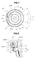
- FIG. 6 is an enlarged view of a main part around the torque sensor shown in FIG. 2 .
- FIG. 7 is a sectional view of the torque sensor, taken along a B-B line of FIG. 6 .
- FIG. 8 is a local enlarged view of FIG. 6 for explaining function and effect of the first embodiment of the present invention.
- FIGS. 9A to 9D show a second embodiment of the torque sensor etc.
- FIG. 9A is a side view of the torque sensor.
- FIG. 9B is a bottom view of the torque sensor.
- FIG. 9C is a longitudinal cross section of the torque sensor, taken along a C-C line of FIG. 9B .
- FIG. 9D is an enlarged view of a main part of FIG. 9C .
- FIGS. 10A to 10D show a comparison example with the second embodiment.
- FIG. 10A is a side view of the torque sensor.
- FIG. 10B is a bottom view of the torque sensor.
- FIG. 10C is a longitudinal cross section of the torque sensor, taken along a D-D line of FIG. 10B .
- FIG. 10D is an enlarged view of a main part of FIG. 10C .
- FIGS. 11A to 11C show a first modification of the second embodiment.
- FIG. 11A is a longitudinal cross section of the torque sensor.
- FIG. 11B is an enlarged view of a main part of FIG. 11A , which shows an influence of a radial direction magnetic flux of an external magnetic field upon magnetic flux concentration rings.
- FIG. 11C is an enlarged view of a main part of FIG. 11A , which shows an influence of an axial direction magnetic flux of the external magnetic field upon the magnetic flux concentration rings.
- FIGS. 12A to 12C show a comparison example with the first modification of the second embodiment.
- FIG. 12A is a longitudinal cross section of the torque sensor.
- FIG. 12B is an enlarged view of a main part of FIG. 12A , which shows an influence of a radial direction magnetic flux of the external magnetic field upon the magnetic flux concentration rings.
- FIG. 12C is an enlarged view of a main part of FIG. 12A , which shows an influence of an axial direction magnetic flux of the external magnetic field upon the magnetic flux concentration rings.
- FIGS. 13A and 13B show a second modification of the second embodiment.
- FIG. 13A is a sectional view of the torque sensor, corresponding to the sectional view taken along the B-B line of FIG. 6 .
- FIG. 13B is a longitudinal cross section, taken along an E-E line of FIG. 13A .
- FIG. 14 is a longitudinal cross section of the torque sensor of a third modification of the second embodiment, corresponding to FIG. 9C .
- FIGS. 1 to 8 show a first embodiment of the torque sensor etc. of the present invention.
- a steering shaft (a rotation member), which is formed by an input shaft 1 (a second shaft member in the present invention) whose one end side is connected to a steering wheel SW and a first output shaft 3 (a first shaft member in the present invention) whose one end side is relatively rotatably connected to the input shaft 1 through a torsion bar 2 , is linked with steered road wheels (not shown) through a first rack-and-pinion gear mechanism RP 1 that is provided at one side, in a vehicle body width direction, of the vehicle.
- a torque sensor TS is set at an outer periphery of the steering shaft, and an electric motor M driven and controlled by an ECU 4 on the basis of an output signal of the torque sensor TS is provided. Further, a second output shaft 6 , to which the electric motor M is coupled via a certain speed reduction gear mechanism 5 (e.g. a worm gear), is linked with the steered road wheels (not shown) through a second rack-and-pinion gear mechanism RP 2 that is provided at the other side, in the vehicle body width direction, of the vehicle.
- a certain speed reduction gear mechanism 5 e.g. a worm gear
- the first rack-and-pinion gear mechanism RP 1 has a pinion gear 3 a that is provided at the other end side of the first output shaft 3 and a first rack teeth (not shown) that is provided at one end side of a rack bar 8 whose both ends are linked with the steered road wheels through tie rods 7 , 7 .
- the second rack-and-pinion gear mechanism RP 2 has a second pinion gear 6 a that is coupled with a top end portion of the second output shaft 6 and a second rack teeth (not shown) that is provided at the other end side of the rack bar 8 .
- the torsion bar 2 twists on the basis of a steering torque inputted to the input shaft 1 from the steering wheel SW, and the first output shaft 3 rotates according to a rotation torque that is generated upon restoring of the torsion bar 2 from or in response to the twist (torsion deformation) of the torsion bar 2 .
- This rotary motion of the first output shaft 3 is converted to a rectilinear motion of the rack bar 8 through the first rack-and-pinion gear mechanism RP 1 .
- the second output shaft 6 rotates according to a steering assist torque that is generated at the electric motor M on the basis of the steering torque, and this rotary motion of the second output shaft 6 is converted to a rectilinear motion of the rack bar 8 through the second rack-and-pinion gear mechanism RP 2 .
- these conversion mechanisms a direction of the steered road wheels is changed while being provided with a steering assist by the electric motor M.
- the first gear housing 10 that houses therein the first rack-and-pinion gear mechanism RP 1 .
- the first gear housing 10 is formed, for instance, by non-magnetic material.
- the first gear housing 10 is formed from a pair of housing forming members of a housing body 11 and a housing cover 12 by connecting these members together with a plurality of bolts 9 arranged in a circumferential direction.
- the housing body 11 is a substantially cylindrical housing that houses therein the whole of the first output shaft 3 .
- the housing cover 12 is a cover that covers or closes one end side opening that is an upper end portion of the housing body 11 .
- the housing body 11 has a large diameter section 11 a formed stepwise by enlarging a diameter of the one end side of the housing body 11 and a small diameter section 11 b having a relatively small diameter and formed by setting a diameter (an inside diameter) of the other side of the housing body 11 to be slightly greater than an outside diameter of the first output shaft 3 . Then, the torque sensor TS is provided at an outer peripheral area of a connection of the input shaft 1 and the first output shaft 3 where the other end portion of the input shaft 1 which is housed in the large diameter section 11 a and the one end portion of the first output shaft 3 are connected.
- a pair of bearings BR 1 , BR 2 are provided at both end portions of the small diameter section 11 b of the housing body 11 , and the first output shaft 3 is rotatably supported by a pair of the bearings BR 1 , BR 2 .
- a bearing BR 3 is also provided at an inner periphery of a constricted portion 12 a formed in a middle in an axial direction of the housing cover 12 , and the input shaft 1 is rotatably supported by the bearing BR 3 .
- the torque sensor TS mainly has a magnetic member 20 , a pair of first and second yoke members 31 , 32 , a pair of first and second magnetic flux concentration rings 51 , 52 and a pair of magnetic sensors 60 , 60 .
- the magnetic member 20 is formed into a substantially cylindrical shape.
- the magnetic member 20 is fixed onto an outer periphery of the one end portion of the first output shaft 3 , then rotates integrally with the first output shaft 3 .
- the first and second yoke members 31 , 32 are formed by soft magnetic material, and have a substantially cylindrical shape.
- the first and second yoke members 31 , 32 are both fixed onto an outer periphery of the other end portion of the input shaft 1 , then rotate integrally with the input shaft 1 .
- the first and second yoke members 31 , 32 are arranged so that each one end side (each lower end portion side in FIG. 6 , which corresponds to after-mentioned first nail portion 41 and second nail portion 42 ) of the first and second yoke members 31 , 32 faces the magnetic member 20 in a radial direction without making contact with the magnetic member 20 .
- the first and second magnetic flux concentration rings 51 , 52 are disposed in a radial direction space formed between the first and second yoke members 31 , 32 at the other end side (upper end portion sides in FIG. 6 , which corresponds to after-mentioned first ring portion 43 and second ring portion 44 ) of the first and second yoke members 31 , 32 .
- the first and second magnetic flux concentration rings 51 , 52 have such substantially ring shape that magnetic field (magnetic flux) generated by the magnetic member 20 and leaking to the other end side of the first and second yoke members 31 , 32 is concentrated or collected in a predetermined area.
- the magnetic sensors 60 , 60 are accommodated between the first and second magnetic flux concentration rings 51 , 52 with the magnetic sensors 60 , 60 spaced a predetermined air gap C 1 from the first and second magnetic flux concentration rings 51 , 52 .
- the magnetic sensors 60 , 60 detect the magnetic flux that passes between the first and second magnetic flux concentration rings 51 , 52 .
- the magnetic member 20 has a ring-shaped permanent magnet 21 formed by magnetic material, a substantially cylindrical sleeve 23 formed by a predetermined metal material, and an insulator 22 formed by a predetermined resin material.
- the permanent magnet 21 has a plurality of different magnetic poles (the north pole (N pole) and the south pole (S pole), in the present embodiment, each 8 poles, all 16 poles) alternately arranged in the circumferential direction.
- One end side of the sleeve 23 is joined to an inner peripheral portion of the permanent magnet 21 in an insulation manner through the resin-made insulator 22 .
- the magnetic member 20 is formed, as one unit, by molding (using a mold) of the permanent magnet 21 and the sleeve 23 with the resin material (the resin-made insulator 22 ). Then, the sleeve 23 is fitted onto a large diameter portion 3 b that is formed stepwise at the outer periphery of the one end portion of the first output shaft 3 , and a top edge of the sleeve 23 is laser-welded along the circumferential direction, the magnetic member 20 is thus fixed onto the outer periphery of the first output shaft 3 through the sleeve 23 .
- the first yoke member 31 is formed into such crank shape in vertically-cut cross section that the one end side (the lower end portion side in FIG. 6 ) of the first yoke member 31 has a relatively large diameter and the other end side (the upper end portion side in FIG. 6 ) of the first yoke member 31 has a relatively small diameter. More specifically, at the one end side (the lower end portion side in FIG. 6 ) of the first yoke member 31 , a plurality of the first nail portions 41 are formed so that its vertically-cut cross section is such inverted L-shape that the one end side of the first yoke member 31 widens or extends in a radially outward direction.
- the first nail portions 41 are set concentrically with the steering shaft (a rotation axis Z) so that the first nail portions 41 are arranged at predetermined circumferential direction intervals at an outer peripheral area of the magnetic member 20 .
- the first ring portion 43 having a ring shape that continues along the circumferential direction of the rotation axis Z is formed.
- the first ring portion 43 connects the first nail portions 41 together by connecting with each base portion of the first nail portions 41 .
- the first yoke member 31 is formed by the first nail portions 41 and the first ring portion 43 , described above.
- the second yoke member 32 is formed into such crank shape in vertically-cut cross section that the one end side (the lower end portion side in FIG. 6 ) of the second yoke member 32 has a relatively small diameter and the other end side (the upper end portion side in FIG. 6 ) of the second yoke member 32 has a relatively large diameter. More specifically, at the one end side (the lower end portion side in FIG. 6 ) of the second yoke member 32 , a plurality of the second nail portions 42 are formed so that its vertically-cut cross section is such inverted L-shape that the one end side of the second yoke member 32 shrinks or shortens in a radially inward direction.
- the second nail portions 42 are set concentrically with the steering shaft (the rotation axis Z) at the outer peripheral area of the magnetic member 20 so that the second nail portions 42 are arranged at predetermined circumferential direction intervals in such a way that the second nail portion 42 and the first nail portion 41 are alternately arranged on the same circumference of a circle as that of the first nail portions 41 .
- the second ring portion 44 having a ring shape that continues along the circumferential direction of the rotation axis Z is formed.
- the second ring portion 44 connects the second nail portions 42 together by connecting with each base portion of the second nail portions 42 .
- the second yoke member 32 is formed by the second nail portions 42 and the second ring portion 44 , described above.
- the first yoke member 31 and the second yoke member 32 are set so that, each first nail portion 41 and each second nail portion 42 are alternately arranged on the same circumference of the circle, also the second ring portion 44 is positioned at outer circumferential side of the first ring portion 43 and is separated from and faces the first ring portion 43 in the radial direction.
- adjoining or adjacent first and second nail portions 41 , 42 are joined to each other through an insulator 33 that is formed by the same resin material as that of the insulator 22 of the magnetic member 20 .
- a substantially cylindrical sleeve 34 formed by predetermined metal material is provided at an inner circumferential side of the first ring portion 43 and joined to the first and second yoke members 31 , 32 through the insulator 33 .
- the first and second yoke members 31 , 32 are then fixed onto the outer periphery of the input shaft 1 through the sleeve 34 .
- the sleeve 34 is fitted onto a large diameter portion 1 b that is formed stepwise at the outer periphery of the other end portion of the input shaft 1 , and a top edge of the sleeve 34 is laser-welded along the circumferential direction, then the first and second yoke members 31 , 32 are fixed onto the outer periphery of the input shaft 1 through the sleeve 34 .
- the first and second nail portions 41 , 42 respectively have first and second axial direction extending portions 41 a , 42 a and first and second radial direction extending portions 41 b , 42 b.
- the first and second axial direction extending portions 41 a , 42 a extend along the axial direction (in a shaft direction) of the rotation axis Z, and face the permanent magnet 21 in the radial direction.
- the first and second radial direction extending portions 41 b , 42 b are provided so as to bend from the first and second axial direction extending portions 41 a , 42 a respectively, and extend along the radial direction of the rotation axis Z.
- each axial direction length of the first and second axial direction extending portions 41 a , 42 a is set to be at least greater than an axial direction length of the permanent magnet 21 . Then, the first and second axial direction extending portions 41 a , 42 a and the permanent magnet 21 are configured so that the permanent magnet 21 is completely enclosed or surrounded with the first and second axial direction extending portions 41 a , 42 a from a radial direction outer side.
- the first and second magnetic flux concentration rings 51 , 52 are formed, by press molding, into an arc-shape having both edges in the circumferential direction and extending over 180 degrees along the circumferential direction so as to surround or enclose the rotation axis Z in a predetermined area over 180 degrees in the circumferential direction of the rotation axis Z.
- the first and second magnetic flux concentration rings 51 , 52 are provided with first and second flat portions 51 a , 52 a (described later), each of which is formed at a part, in the radial direction, of the first and second magnetic flux concentration rings 51 , 52 so as to face each other. Then, a pair of the magnetic sensors 60 , 60 are accommodated in a radial direction space C 4 (see FIG. 6 ) formed by the first and second flat portions 51 a , 52 a.
- the first magnetic flux concentration ring 51 is formed into a substantially ring shape that extends or ranges over a wide area in the circumferential direction of nearly 320 degrees, also the first magnetic flux concentration ring 51 is provided, at an opposite side (at a position symmetrical about a center) to a first cutting portion 51 c formed by being cut in the circumferential direction, with the first flat portion 51 a that is a first sensor facing area.
- the first flat portion 51 a is formed by the fact that a certain circumferential direction area positioned at the opposite side to the first cutting portion 51 c protrudes in the radially outward direction so as to have convex shape or protuberance in horizontally-cut cross section.
- the second magnetic flux concentration ring 52 is formed into a substantially ring shape that extends or ranges over an area in the circumferential direction of nearly 290 degrees that is narrower than the first magnetic flux concentration ring 51 , also the second magnetic flux concentration ring 52 is provided, at an opposite side (at a position symmetrical about a center) to a second cutting portion 52 c formed by being cut in the circumferential direction, with the second flat portion 52 a that is a second sensor facing area.
- the second flat portion 52 a is formed by the fact that a certain circumferential direction area positioned at the opposite side to second cutting portion 52 c is pressed in the radially inward direction so as to become a flat shape.
- both of the first and second magnetic flux concentration rings 51 , 52 are formed into C-shaped ring in horizontally-cut cross section which extends over 180 degrees along the circumferential direction so as to surround the rotation axis Z in the predetermined area over 180 degrees in the circumferential direction of the rotation axis Z.
- first flat portion 51 a when a circumferential direction outer side area of the first flat portion 51 a is termed a first arc portion 51 b , the first flat portion 51 a is offset to an outer side so that a radial direction space C 5 between the first flat portion 51 a and the first ring portion 43 is at least greater than the radial direction gap C 2 between the first arc portion 51 b and the first ring portion 43 (i.e. C 2 ⁇ C 5 ).
- the second flat portion 52 a when a circumferential direction outer side area of the second flat portion 52 a is termed a second arc portion 52 b , the second flat portion 52 a is offset to an inner side so that a radial direction space C 6 between the second flat portion 52 a and the second ring portion 44 is at least greater than the radial direction gap C 3 between the second arc portion 52 b and the second ring portion 44 (i.e. C 3 ⁇ C 6 ).
- the first and second magnetic flux concentration rings 51 , 52 are joined to each other through an insulator 53 (see FIG. 2 ) that is formed by the same resin material as that of the insulators 22 and 33 of the magnetic member 20 and the first and second yoke members 31 , 32 . Also, the first and second magnetic flux concentration rings 51 , 52 are fixed to the large diameter section 11 a of the housing body 11 through the insulator 53 by a certain fixing manner (e.g. with bolts) so that at least a part of an axial direction area X (see FIG.
- first and second magnetic flux concentration rings 51 , 52 overlaps with the first and second ring portions 43 , 44 in the axial direction when viewed from the radial direction (at least a part of an axial direction area X of the first and second magnetic flux concentration rings 51 , 52 and the first and second ring portions 43 , 44 are arranged in layers in the radial direction) between the first and second ring portions 43 , 44 .
- a pair of the magnetic sensors 60 , 60 are accommodated in the radial direction space C 4 between the first and second magnetic flux concentration rings 51 , 52 .
- Each of the magnetic sensors 60 , 60 has a detecting portion 61 that is a Hall IC and a connecting terminal 62 .
- the detecting portion 61 has thereinside a Hall device and detects, by the Hall device, the magnetic field (the magnetic flux) that passes between the first and second magnetic flux concentration rings 51 , 52 (between the first and second flat portions 51 a , 52 a ).
- the connecting terminal 62 is a terminal to connect the detecting portion 61 to a control board 63 (a circuit board, see FIG. 2 ) located above the torque sensor TS.
- each magnetic sensor 60 itself is secured by being connected to the control board 63 through the connecting terminal 62 , and the magnetic sensors 60 , 60 are accommodated in the radial direction space C 4 between the first and second magnetic flux concentration rings 51 , 52 (the first and second flat portions 51 a , 52 a ) with the magnetic sensors 60 , 60 spaced the predetermined air gap C 1 from first and second magnetic flux concentration rings 51 , 52 (the first and second flat portions 51 a , 52 a ).
- the magnetic sensors 60 , 60 detect, by using the Hall effect by the Hall device, magnetic flux density that passes between the first and second magnetic flux concentration rings 51 , 52 by the detecting portions 61 , 61 . Then, a torque operation in the control board 63 is performed using an output signal that changes according to the detected magnetic flux density from the detecting portions 61 , 61 .
- the control board 63 is connected to the ECU 4 (see FIG. 1 ) through a board-to-board connector 64 (also a harness) that is drawn to an inside of the housing body 11 via a window hole 11 c formed on a side surface of the large diameter section 11 a of the housing body 11 .
- the window hole 11 c is located at an axial direction one side of the rotation axis Z (at an upper end portion side in FIG.
- each boundary between the magnetic poles of the permanent magnet 21 is positioned exactly in a middle position in the circumferential direction between the first and second nail portions 41 , 42 , then magnetic path resistances of the permanent magnet 21 with respect to the first and second nail portions 41 , 42 are equal to each other.
- the magnetic field generated in the permanent magnet 21 is short-circuited between the first and second nail portions 41 , 42 , and the magnetic field does not leak to the first and second ring portions 43 , 44 .
- the magnetic flux of the magnetic field is thus not detected by each magnetic sensor 60 .
- each boundary between the magnetic poles of the permanent magnet 21 shifts to one side in the circumferential direction of the first and second nail portions 41 , 42 , then magnetic path resistance of the one side to which each boundary shifts in the circumferential direction, among the magnetic path resistances of the permanent magnet 21 with respect to the first and second nail portions 41 , 42 , becomes large.
- the magnetic field generated in the permanent magnet 21 leaks to the first and second ring portions 43 , 44 and flows to adjacent magnetic poles through the first and second ring portions 43 , 44 .
- the magnetic flux passes from one side to the other side between the first and second magnetic flux concentration rings 51 , 52 , and the magnetic flux density is detected by the magnetic sensors 60 , 60 .
- an operation (calculation) of the steering assist torque by the electric motor M is performed in the ECU 4 .
- a steering direction and a providing direction of the steering assist torque are judged or determined by a direction of the magnetic flux passing between the first and second magnetic flux concentration rings 51 , 52 .
- the torque sensor TS upon detection of the torque, as same as the related art torque sensor, also the torque sensor TS is not shielded by using a certain shielding member.
- a certain shielding member As shown in FIG. 8 , not only an internal magnetic field by the permanent magnet 21 but also some external magnetic field OF which is unrelated to the permanent magnet 21 act on the first and second magnetic flux concentration rings 51 , 52 .
- a part of the axial direction area X of the first and second magnetic flux concentration rings 51 , 52 is accommodated in a radial direction space between the first and second ring portions 43 , 44 , and overlaps with the first and second ring portions 43 , 44 in the axial direction when viewed from the radial direction (a part of the axial direction area X of the first and second magnetic flux concentration rings 51 , 52 and the first and second ring portions 43 , 44 are arranged in layers in the radial direction).
- a radial direction magnetic flux RF among the external magnetic field OF which relates to a part of the axial direction area X accommodated between the first and second ring portions 43 , 44 , is received by the second ring portion 44 of the second yoke member 32 which is arranged at an outermost circumference. Therefore, when the radial direction magnetic flux RF received by the second ring portion 44 acts on the second magnetic flux concentration ring 52 through the second ring portion 44 , the radial direction magnetic flux RF is attenuated to some extent by an air gap of the radial direction space C 6 . The action of the external magnetic field OF on a part of the axial direction area X is consequently reduced or diminished as compared with a case where the external magnetic field OF directly acts on the both magnetic flux concentration rings 51 , 52 like the related art torque sensor.
- the torque sensor TS (the power steering system using the torque sensor TS) of the present embodiment
- a part of the axial direction area X of the first and second magnetic flux concentration rings 51 , 52 is shielded (surrounded or enclosed) by the second ring portion 44 of the second yoke member 32 which is arranged at an outer circumferential side of a part of the axial direction area X
- the action (transmission) of the external magnetic field OF on (to) the first and second magnetic flux concentration rings 51 , 52 is suppressed by the second ring portion 44 .
- the toque detection accuracy by the magnetic sensor 60 which tends to decrease due to the external magnetic field (due to detection of the external magnetic field), can be improved.
- the radial direction space C 6 between the second flat portion 52 a and the second ring portion 44 is set to be greater than the radial direction gap C 3 between the second arc portion 52 b and the second ring portion 44 (i.e. C 3 ⁇ C 6 ).
- this space setting (C 3 ⁇ C 6 ) it is possible to increase an attenuation effect of the external magnetic field OF.
- the external magnetic field OF transmitted through the second ring portion 44 bypasses the second flat portion 52 a and is transmitted to the second arc portion 52 b where the radial direction gap C 3 between the second arc portion 52 b and the second ring portion 44 is small (magnetic path resistance is small) as compared with the radial direction space C 6 , a transmission route of the external magnetic field OF to the magnetic sensors 60 , 60 extends. As a consequence, ill effects of the external magnetic field OF on the torque detection can be effectively reduced.
- the first flat portion 51 a is formed so as to protrude to the outer side so that the radial direction space C 5 between the first flat portion 51 a and the first ring portion 43 is greater than the radial direction gap C 2 between the first arc portion 51 b and the first ring portion 43 (i.e. C 2 ⁇ C 5 ).
- this space setting (C 2 ⁇ C 5 ) the radial direction space C 4 between the first and second flat portions 51 a , 52 a becomes narrow, then the torque detection accuracy by the magnetic sensor 60 can be improved.
- a circumferential length (an entire length) of the first magnetic flux concentration ring 51 which tends to be shorter than that of the second magnetic flux concentration ring 52 due to the fact that the first magnetic flux concentration ring 51 is arranged at the inner circumferential side, elongates, thereby equalizing both magnetic path resistances of the first and second magnetic flux concentration rings 51 , 52 .
- the first and second magnetic flux concentration rings 51 , 52 are formed so that, a circumferential direction angle area of the first magnetic flux concentration ring 51 positioned at the inner circumferential side is narrower, and a circumferential direction angle area of the second magnetic flux concentration ring 52 positioned at the outer circumferential side is wider, namely that, as shown in FIG. 7 , a circumferential direction length L 2 (a circumferential direction opening length L 2 ) of the second cutting portion 52 c is greater than a circumferential direction length L 1 (a circumferential direction opening length L 1 ) of the first cutting portion 51 c (i.e. L 1 ⁇ L 2 ).
- both circumferential lengths of the first and second magnetic flux concentration rings 51 , 52 are substantially equalized, and this also brings about equalization of the both magnetic path resistances of the first and second magnetic flux concentration rings 51 , 52 .
- both circumferential direction angle areas of the first and second magnetic flux concentration rings 51 , 52 are set to be equal to each other, an opposing area between the second magnetic flux concentration ring 52 and the second ring portion 44 becomes greater by an area equivalent to the circumferential direction length of the second magnetic flux concentration ring 52 which is longer than that of the first magnetic flux concentration ring 51 due to the fact that the second magnetic flux concentration ring 52 is positioned at the outer circumferential side.
- an efficiency of the magnetic flux concentration of the second magnetic flux concentration ring 52 is increased, and this results in an unbalanced state of the magnetic path resistances of the first and second magnetic flux concentration rings 51 , 52 .
- the first and second magnetic flux concentration rings 51 , 52 are configured to be surrounded or enclosed with the second ring portion 44 , and the both magnetic flux concentration rings 51 , 52 are arranged only at the outer circumferential side of the first ring portion 43 .
- an axial direction external magnetic field an axial direction magnetic flux AF
- first and second magnetic flux concentration rings 51 , 52 are arranged at both inner and outer circumferential sides of the first ring portion 43 , a member to magnetically connect the first and second magnetic flux concentration rings 51 , 52 is required with this connecting member arranged across the first ring portion 43 , and this connecting member is easily affected by the external magnetic field from the axial direction.
- this problem can be avoided.
- the window hole 11 c is arranged at the position where the window hole 11 c does not interfere with the first and second yoke members 31 , 32 and the first and second magnetic flux concentration rings 51 , 52 .
- This arrangement avoids a problem that the external magnetic field entering the housing 10 through the window hole 11 c directly acts on the first and second magnetic flux concentration rings 51 , 52 .
- FIGS. 9A to 9D show a second embodiment of the torque sensor etc. of the present invention.
- the configuration of the first and second yoke members 31 , 32 of the first embodiment is changed.
- first and second radial direction extending portions 41 b , 42 b of the first and second nail portions 41 , 42 of the first and second yoke members 31 , 32 are removed.
- first and second connecting portions 45 , 46 are formed by the fact that an entire circumference of each base end portion of the first and second ring portions 43 , 44 bends and extends in the radial direction of the rotation axis Z.
- first and second connecting portions 45 , 46 are formed between the first and second nail portions 41 , 42 (corresponding to the first and second axial direction extending portions 41 a , 42 a ) and the first and second ring portions 43 , 44 respectively of the first embodiment so as to extend in the radial direction and shield (cover or close) a bottom side of a magnetic flux concentration ring accommodating portion 50 that is formed between the first and second ring portions 43 , 44 .
- the first and second connecting portions 45 , 46 connects the first nail portion 41 and the first ring portion 43 and connects the second nail portion 42 and the second ring portion 44 .
- FIGS. 11A to 11C show a first modification of the second embodiment of the torque sensor etc. of the present invention.
- the first and second magnetic flux concentration rings 51 , 52 are arranged so as to be completely accommodated in the magnetic flux concentration ring accommodating portion 50 , and whole axial direction areas of the first and second magnetic flux concentration rings 51 , 52 overlap with the second ring portion 44 (also with the first ring portion 43 ) in the axial direction when viewed from the radial direction (whole axial direction areas of the first and second magnetic flux concentration rings 51 , 52 and the second ring portion 44 (also the first ring portion 43 ) are arranged in layers in the radial direction).
- the first and second magnetic flux concentration rings 51 , 52 are unaffected by both of the axial direction magnetic flux AF and the radial direction magnetic flux RF of the external magnetic field OF.
- the ill effects of the external magnetic field OF on the torque detection can therefore be suppressed more effectively.
- FIGS. 13A and 13B show a second modification of the second embodiment of the torque sensor etc. of the present invention.
- the radial direction gap C 3 between the second magnetic flux concentration ring 52 and the second ring portion 44 is set to be greater than the radial direction gap C 2 between the first magnetic flux concentration ring 51 and the first ring portion 43 (i.e. C 2 ⁇ C 3 ).
- both magnetic path resistances of the first and second magnetic flux concentration rings 51 , 52 can be adjusted, then both magnetic path resistances of the first and second magnetic flux concentration rings 51 , 52 are equalized.
- both radial direction gaps C 2 , C 3 are set to be equal to each other, an opposing area between the second magnetic flux concentration ring 52 and the second ring portion 44 becomes greater by an area equivalent to the circumferential direction length of the second magnetic flux concentration ring 52 which is longer than that of the first magnetic flux concentration ring 51 due to the fact that the second magnetic flux concentration ring 52 is positioned at the outer circumferential side.
- an efficiency of the magnetic flux concentration of the second magnetic flux concentration ring 52 is increased, and this results in an unbalanced state of the magnetic path resistances of the first and second magnetic flux concentration rings 51 , 52 .
- FIG. 14 shows a third modification of the second embodiment of the torque sensor etc. of the present invention.
- an axial direction length L 4 of the second magnetic flux concentration ring 52 is set to be smaller (shorter) than an axial direction length L 3 of the first magnetic flux concentration ring 51 (i.e. L 4 ⁇ L 3 ).
- the axial direction length L 4 of the second magnetic flux concentration ring 52 arranged at the outer circumferential side is set to be relatively small, an opposing area between the first magnetic flux concentration ring 51 and the first ring portion 43 and an opposing area between the second magnetic flux concentration ring 52 and the second ring portion 44 can be adjusted, then both efficiencies of the magnetic flux concentration of the first and second magnetic flux concentration rings 51 , 52 are equalized.
- both axial direction lengths L 3 , L 4 are set to be equal to each other, the opposing area between the second magnetic flux concentration ring 52 and the second ring portion 44 becomes greater by an area equivalent to the circumferential direction length of the second magnetic flux concentration ring 52 which is longer than that of the first magnetic flux concentration ring 51 due to the fact that the second magnetic flux concentration ring 52 is positioned at the outer circumferential side.
- the efficiency of the magnetic flux concentration of the second magnetic flux concentration ring 52 is increased, and this results in an unbalanced state of the magnetic path resistances of the first and second magnetic flux concentration rings 51 , 52 .
- the present invention is not limited to the above embodiments and modifications. Not only configurations or structures of, for instance, the housing 10 and the first and second rack-and-pinion gear mechanism RP 1 , RP 2 , with which the present invention is not directly concerned as a feature, but also configuration or structure of the magnetic member 20 , the first and second yoke members 31 , 32 and the first and second magnetic flux concentration rings 51 , 52 (the first and second magnetic flux concentration members 54 , 55 ), which are the features of the present invention, can be freely changed or modified according to specifications of the vehicle and the torque sensor.
- the torque sensor TS is explained with the torque sensor TS applied to a so-called dual pinion type power steering system in which the steering system and the assist system are provided independently of each other.
- the power steering system according to the present invention which employs the torque sensor TS, as long as the power steering system is the one that is controlled on the basis of the torque detection of the torque sensor TS such as a so-called single pinion type power steering system in which the second output shaft 6 is removed and the electric motor M is coupled with the first output shaft 3 via the speed reduction gear mechanism 5 , the present invention can be applied to any power steering systems.
- first nail portions 41 and the second nail portions 42 are concentrically arranged.
- this arrangement could be changed as long as the both nail portions 41 , 42 are set concentrically with the rotation axis Z.
- first and second nail portions 41 , 42 could be arranged so that an air gap between the first nail portion 41 and the permanent magnet 21 and an air gap between the second nail portion 42 and the permanent magnet 21 are different from each other.
- first and second nail portions 41 , 42 might be arranged so that the first nail portions 41 are arranged at an inner circumferential side of the permanent magnet 21 and the second nail portions 42 are arranged at an outer circumferential side of the permanent magnet 21 while keeping the air gaps between the first nail portion 41 and the permanent magnet 21 and between the second nail portion 42 and the permanent magnet 21 .
- the second magnetic flux concentration ring ( 52 ) is set so that a radial direction space (C 6 ) between the second magnetic flux concentration ring ( 52 ) and the second ring portion ( 44 ) at a second sensor facing area ( 52 a ) of the second magnetic flux concentration ring ( 52 ) where the second magnetic flux concentration ring ( 52 ) faces the magnetic sensor ( 60 ) in the radial direction is greater than a radial direction gap (C 3 ) between the second magnetic flux concentration ring ( 52 ) and the second ring portion ( 44 ) at a circumferential direction outer side area ( 52 b ) of the second magnetic flux concentration ring ( 52 ) except the second sensor facing area ( 52 a ).
- the torque sensor of (a) by setting the radial direction space (C 6 ) between the second magnetic flux concentration ring ( 52 ) and the second ring portion ( 44 ) at the second sensor facing area ( 52 a ) to be relatively great, the external magnetic field transmitted through the second ring portion ( 44 ) bypasses the second sensor facing area ( 52 a ) and is transmitted to the circumferential direction outer side area ( 52 b ) where the radial direction gap (C 3 ) is small (magnetic path resistance is small) as compared with the radial direction space (C 6 ).
- the transmission route of the external magnetic field to the magnetic sensor ( 60 ) therefore extends. As a consequence, ill effects of the external magnetic field on the torque detection can be effectively reduced.
- the first magnetic flux concentration ring ( 51 ) is configured so that a first sensor facing area ( 51 a ) of the first magnetic flux concentration ring ( 51 ) where the first magnetic flux concentration ring ( 51 ) faces the magnetic sensor ( 60 ) in the radial direction protrudes in a radially outward direction with respect to a circumferential direction outer side area ( 51 b ) of the first magnetic flux concentration ring ( 51 ) except the first sensor facing area ( 51 a ).
- the radial direction space (C 4 ) between the first and second flat portions ( 51 a , 52 a ) becomes narrow, and also the circumferential length (an entire length) of the first magnetic flux concentration ring ( 51 ), which tends to be shorter than that of the second magnetic flux concentration ring ( 52 ) due to the fact that the first magnetic flux concentration ring ( 51 ) is arranged at the inner circumferential side, elongates, thereby equalizing both magnetic path resistances of the first and second magnetic flux concentration rings ( 51 , 52 ).
- the first and second magnetic flux concentration rings ( 51 , 52 ) are configured so that a circumferential direction angle area that surrounds the rotation axis (Z) by the second magnetic flux concentration ring ( 52 ) is smaller than a circumferential direction angle area that surrounds the rotation axis (Z) by the first magnetic flux concentration ring ( 51 ).
- both circumferential direction angle areas of the first and second magnetic flux concentration rings ( 51 , 52 ) are set to be equal to each other, an opposing area between the second magnetic flux concentration ring ( 52 ) and the second ring portion ( 44 ) becomes greater by an area equivalent to the circumferential direction length of the second magnetic flux concentration ring ( 52 ) which is longer than that of the first magnetic flux concentration ring ( 51 ) due to the fact that the second magnetic flux concentration ring ( 52 ) is positioned at the outer circumferential side.
- an efficiency of the magnetic flux concentration of the second magnetic flux concentration ring ( 52 ) is increased, and this results in an unbalanced state of the magnetic path resistances of the first and second magnetic flux concentration rings ( 51 , 52 ).
- both magnetic path resistances of the first and second magnetic flux concentration rings ( 51 , 52 ) which are arranged in layers each other in the radial direction are equalized.
- the first and second magnetic flux concentration rings ( 51 , 52 ) are configured so that an axial direction length (L 4 ) of the second magnetic flux concentration ring ( 52 ) is shorter than an axial direction length (L 3 ) of the first magnetic flux concentration ring ( 51 ).
- both axial direction lengths (L 3 , L 4 ) are set to be equal to each other, the opposing area between the second magnetic flux concentration ring ( 52 ) and the second ring portion ( 44 ) becomes greater by an area equivalent to the circumferential direction length of the second magnetic flux concentration ring ( 52 ) which is longer than that of the first magnetic flux concentration ring ( 51 ) due to the fact that the second magnetic flux concentration ring ( 52 ) is positioned at the outer circumferential side.
- the efficiency of the magnetic flux concentration of the second magnetic flux concentration ring ( 52 ) is increased, and this results in an unbalanced state of the magnetic path resistances of the first and second magnetic flux concentration rings ( 51 , 52 ).
- the first and second magnetic flux concentration rings ( 51 , 52 ) are configured so that a radial direction gap (C 3 ) between the second magnetic flux concentration ring ( 52 ) and the second ring portion ( 44 ) is greater than a radial direction gap (C 2 ) between the first magnetic flux concentration ring ( 51 ) and the first ring portion ( 43 ).
- both radial direction gaps (C 2 , C 3 ) are set to be equal to each other, an opposing area between the second magnetic flux concentration ring ( 52 ) and the second ring portion ( 44 ) becomes greater by an area equivalent to the circumferential direction length of the second magnetic flux concentration ring ( 52 ) which is longer than that of the first magnetic flux concentration ring ( 51 ) due to the fact that the second magnetic flux concentration ring ( 52 ) is positioned at the outer circumferential side.
- an efficiency of the magnetic flux concentration of the second magnetic flux concentration ring ( 52 ) is increased, and this results in an unbalanced state of the magnetic path resistances of the first and second magnetic flux concentration rings ( 51 , 52 ).
- the second ring portion ( 44 ) is configured so that whole axial direction areas of the first and second magnetic flux concentration rings ( 51 , 52 ) overlap with the second ring portion ( 44 ) in an axial direction when viewed from the radial direction.
- the first magnetic flux concentration ring ( 51 ) is configured to surround the rotation axis (Z) in a circumferential direction angle area over 180 degrees.
- the torque sensor (TS) further has a housing ( 10 ) that is formed by non-magnetic material; and a harness that is drawn to an inside of the housing ( 10 ) through a window hole ( 11 c ) formed to penetrate the housing ( 10 ) and transports a detection signal of the magnetic sensor ( 60 ) to an external device.
- the window hole ( 11 c ) is located at an offset position in an axial direction with respect to the first and second magnetic flux concentration rings ( 51 , 52 ).
- the first and second magnetic flux concentration rings ( 51 , 52 ) are formed by press molding.
- the first magnetic flux concentration ring ( 51 ) is arranged only at an outer circumferential side of the first ring portion ( 43 ) of the first yoke member ( 31 ).
- first and second magnetic flux concentration rings ( 51 , 52 ) are arranged at both inner and outer circumferential sides of the first ring portion ( 43 ), a member to magnetically connect the first and second magnetic flux concentration rings ( 51 , 52 ) is required with this connecting member arranged across the first ring portion ( 43 ), and this connecting member is easily affected by the external magnetic field from the axial direction.
- the second ring portion ( 44 ) is formed so that a diameter of the second ring portion ( 44 ) is greater than a diameter of a virtual circle that is formed by connecting the second nail portions ( 42 ), and a second connecting portion ( 46 ) that connects the second ring portion ( 44 ) and each second nail portion ( 42 ) is formed so as to extend from each base end portion of the second nail portions ( 42 ) to a radially outward direction.
- the second connecting portion ( 46 ) it is possible to reduce the influence of the external magnetic field that enters the magnetic flux concentration ring accommodating portion ( 50 ) from an axial direction outer side.
- the second magnetic flux concentration ring ( 52 ) is set so that a radial direction space (C 6 ) between the second magnetic flux concentration ring ( 52 ) and the second ring portion ( 44 ) at a second sensor facing area ( 52 a ) of the second magnetic flux concentration ring ( 52 ) where the second magnetic flux concentration ring ( 52 ) faces the magnetic sensor ( 60 ) in the radial direction is greater than a radial direction gap (C 3 ) between the second magnetic flux concentration ring ( 52 ) and the second ring portion ( 44 ) at a circumferential direction outer side area ( 52 b ) of the second magnetic flux concentration ring ( 52 ) except the second sensor facing area ( 52 a ).
- the external magnetic field transmitted through the second ring portion ( 44 ) bypasses the second sensor facing area ( 52 a ) and is transmitted to the circumferential direction outer side area ( 52 b ) where the radial direction gap (C 3 ) is small (magnetic path resistance is small) as compared with the radial direction space (C 6 ).
- the transmission route of the external magnetic field to the magnetic sensor ( 60 ) therefore extends. As a consequence, ill effects of the external magnetic field on the torque detection can be effectively reduced.
- the first magnetic flux concentration ring ( 51 ) is configured so that a first sensor facing area ( 51 a ) of the first magnetic flux concentration ring ( 51 ) where the first magnetic flux concentration ring ( 51 ) faces the magnetic sensor ( 60 ) in the radial direction protrudes in a radially outward direction with respect to a circumferential direction outer side area ( 51 b ) of the first magnetic flux concentration ring ( 51 ) except the first sensor facing area ( 51 a ).
- the radial direction space (C 4 ) between the first and second flat portions ( 51 a , 52 a ) becomes narrow, and also the circumferential length (an entire length) of the first magnetic flux concentration ring ( 51 ), which tends to be shorter than that of the second magnetic flux concentration ring ( 52 ) due to the fact that the first magnetic flux concentration ring ( 51 ) is arranged at the inner circumferential side, elongates, thereby equalizing both magnetic path resistances of the first and second magnetic flux concentration rings ( 51 , 52 ).
- the first and second magnetic flux concentration rings ( 51 , 52 ) are configured so that a circumferential direction angle area that surrounds the rotation axis (Z) by the second magnetic flux concentration ring ( 52 ) is smaller than a circumferential direction angle area that surrounds the rotation axis (Z) by the first magnetic flux concentration ring ( 51 ).
- both circumferential direction angle areas of the first and second magnetic flux concentration rings ( 51 , 52 ) are set to be equal to each other, an opposing area between the second magnetic flux concentration ring ( 52 ) and the second ring portion ( 44 ) becomes greater by an area equivalent to the circumferential direction length of the second magnetic flux concentration ring ( 52 ) which is longer than that of the first magnetic flux concentration ring ( 51 ) due to the fact that the second magnetic flux concentration ring ( 52 ) is positioned at the outer circumferential side.
- an efficiency of the magnetic flux concentration of the second magnetic flux concentration ring ( 52 ) is increased, and this results in an unbalanced state of the magnetic path resistances of the first and second magnetic flux concentration rings ( 51 , 52 ).
- both magnetic path resistances of the first and second magnetic flux concentration rings ( 51 , 52 ) which are arranged in layers each other in the radial direction are equalized.
- the first and second magnetic flux concentration rings ( 51 , 52 ) are configured so that an axial direction length (L 4 ) of the second magnetic flux concentration ring ( 52 ) is shorter than an axial direction length (L 3 ) of the first magnetic flux concentration ring ( 51 ).
- both axial direction lengths (L 3 , L 4 ) are set to be equal to each other, the opposing area between the second magnetic flux concentration ring ( 52 ) and the second ring portion ( 44 ) becomes greater by an area equivalent to the circumferential direction length of the second magnetic flux concentration ring ( 52 ) which is longer than that of the first magnetic flux concentration ring ( 51 ) due to the fact that the second magnetic flux concentration ring ( 52 ) is positioned at the outer circumferential side.
- the efficiency of the magnetic flux concentration of the second magnetic flux concentration ring ( 52 ) is increased, and this results in an unbalanced state of the magnetic path resistances of the first and second magnetic flux concentration rings ( 51 , 52 ).
- the first and second magnetic flux concentration rings ( 51 , 52 ) are configured so that a radial direction gap (C 3 ) between the second magnetic flux concentration ring ( 52 ) and the second ring portion ( 44 ) is greater than a radial direction gap (C 2 ) between the first magnetic flux concentration ring ( 51 ) and the first ring portion ( 43 ).
- both radial direction gaps (C 2 , C 3 ) are set to be equal to each other, an opposing area between the second magnetic flux concentration ring ( 52 ) and the second ring portion ( 44 ) becomes greater by an area equivalent to the circumferential direction length of the second magnetic flux concentration ring ( 52 ) which is longer than that of the first magnetic flux concentration ring ( 51 ) due to the fact that the second magnetic flux concentration ring ( 52 ) is positioned at the outer circumferential side.
- an efficiency of the magnetic flux concentration of the second magnetic flux concentration ring ( 52 ) is increased, and this results in an unbalanced state of the magnetic path resistances of the first and second magnetic flux concentration rings ( 51 , 52 ).
Landscapes
- Physics & Mathematics (AREA)
- Engineering & Computer Science (AREA)
- General Physics & Mathematics (AREA)
- Electromagnetism (AREA)
- Chemical & Material Sciences (AREA)
- Combustion & Propulsion (AREA)
- Transportation (AREA)
- Mechanical Engineering (AREA)
- Power Steering Mechanism (AREA)
Applications Claiming Priority (2)
| Application Number | Priority Date | Filing Date | Title |
|---|---|---|---|
| JP2012202208A JP5899090B2 (ja) | 2012-09-14 | 2012-09-14 | トルクセンサ |
| JP2012-202208 | 2012-09-14 |
Publications (2)
| Publication Number | Publication Date |
|---|---|
| US20140076655A1 US20140076655A1 (en) | 2014-03-20 |
| US9302700B2 true US9302700B2 (en) | 2016-04-05 |
Family
ID=50202932
Family Applications (1)
| Application Number | Title | Priority Date | Filing Date |
|---|---|---|---|
| US13/851,585 Active 2034-06-12 US9302700B2 (en) | 2012-09-14 | 2013-03-27 | Torque sensor and power steering system using the torque sensor |
Country Status (5)
| Country | Link |
|---|---|
| US (1) | US9302700B2 (fr) |
| JP (1) | JP5899090B2 (fr) |
| CN (1) | CN103661595B (fr) |
| DE (1) | DE102013008205A1 (fr) |
| FR (1) | FR2995680B1 (fr) |
Cited By (5)
| Publication number | Priority date | Publication date | Assignee | Title |
|---|---|---|---|---|
| US20190072445A1 (en) * | 2015-12-18 | 2019-03-07 | Valeo Schalter Und Sensoren Gmbh | Stator holder, stator module method for assembling a stator module, torque sensor device having a stator module and a stator holder, and motor vehicle having a torque sensor device |
| FR3093181A1 (fr) | 2019-02-25 | 2020-08-28 | Moving Magnet Technologies | Capteur de position, notamment destiné à la détection de la torsion d'une colonne de direction. |
| US10976209B2 (en) | 2015-06-02 | 2021-04-13 | Hitachi Automotive Systems, Ltd. | Torque sensor and electric power steering apparatus |
| US11035745B2 (en) * | 2017-03-31 | 2021-06-15 | Soken, Inc. | Torque sensor |
| US11529989B2 (en) * | 2016-09-20 | 2022-12-20 | Hitachi Astemo, Ltd. | Steering apparatus |
Families Citing this family (23)
| Publication number | Priority date | Publication date | Assignee | Title |
|---|---|---|---|---|
| JP5899090B2 (ja) | 2012-09-14 | 2016-04-06 | 日立オートモティブシステムズステアリング株式会社 | トルクセンサ |
| JP5978079B2 (ja) * | 2012-09-14 | 2016-08-24 | 日立オートモティブシステムズ株式会社 | トルクセンサ |
| CN106471347B (zh) * | 2014-07-09 | 2019-03-05 | 日立汽车系统株式会社 | 旋转角检测装置及动力转向装置 |
| JP6295483B2 (ja) * | 2014-09-19 | 2018-03-20 | 日立オートモティブシステムズ株式会社 | パワーステアリング装置およびパワーステアリング装置の組み立て方法 |
| CN104483052B (zh) * | 2014-12-26 | 2017-04-26 | 南京华敏电子有限公司 | 一种磁敏式扭矩传感器的磁路结构 |
| JP6487817B2 (ja) * | 2015-09-24 | 2019-03-20 | Kyb株式会社 | 電動パワーステアリング装置 |
| CN106979836A (zh) * | 2016-01-19 | 2017-07-25 | 旭春股份有限公司 | 用于转向系统的磁性扭力感应装置 |
| JP6565065B2 (ja) * | 2016-06-08 | 2019-08-28 | 日立オートモティブシステムズ株式会社 | トルクセンサ |
| JP6631843B2 (ja) * | 2016-09-23 | 2020-01-15 | 日立オートモティブシステムズ株式会社 | トルクセンサおよび電動パワーステアリング装置 |
| CN108512365B (zh) * | 2018-04-18 | 2024-08-02 | 上海马陆日用友捷汽车电气有限公司 | 一种直流电动机 |
| CN108562224A (zh) * | 2018-04-20 | 2018-09-21 | 张博熙 | 汽车智能转向系统扭矩和角度传感器 |
| JP7149141B2 (ja) * | 2018-09-18 | 2022-10-06 | 日立Astemo株式会社 | ステアリング装置 |
| DE102018216477B4 (de) | 2018-09-26 | 2023-03-16 | Robert Bosch Gmbh | Lenkvorrichtung mit einer Steckverbindereinheit zur elektrischen Kontaktierung einer Lenksensoreinheit |
| DE102018216449B4 (de) | 2018-09-26 | 2022-06-09 | Robert Bosch Gmbh | Lenkvorrichtung mit einer Steckverbindereinheit zur elektrischen Kontaktierung einer Lenksensoreinheit |
| DE102018131712A1 (de) * | 2018-12-11 | 2020-06-18 | Thyssenkrupp Ag | Magnetische Abschirmung eines Drehmomentsensors für eine elektromechanische Hilfskraftlenkung eines Kraftfahrzeugs |
| JP7514599B2 (ja) * | 2018-12-21 | 2024-07-11 | 株式会社ジェイテクト | 操舵システム |
| DE102019214173B4 (de) * | 2019-09-18 | 2024-03-07 | Robert Bosch Gmbh | Lenkvorrichtung mit einer Steckverbindereinheit zur elektrischen Kontaktierung einer Lenksensoreinheit |
| CN110631612A (zh) * | 2019-10-02 | 2019-12-31 | 北京金钢科技有限公司 | 紧凑型一体化多组分离式磁编码器 |
| DE102020109469A1 (de) * | 2020-04-03 | 2021-10-07 | Bourns, Inc. | Sensor zum Erfassen eines Drehmomentes |
| CN111568301B (zh) * | 2020-06-16 | 2025-07-18 | 北京石头世纪科技股份有限公司 | 安装支架及机器人 |
| DE102021204232A1 (de) | 2021-04-28 | 2022-11-03 | Robert Bosch Gesellschaft mit beschränkter Haftung | Lenkvorrichtung mit einer Lenksensoreinheit zur induktiven Erfassung wenigstens einer Lenkinformation |
| CN116929615B (zh) * | 2023-09-18 | 2023-12-01 | 深圳市鑫精诚传感技术有限公司 | 一种电磁式复合多轴扭矩传感器及扭矩测量方法 |
| DE102024118450A1 (de) * | 2024-06-28 | 2025-12-31 | Volkswagen Aktiengesellschaft | Vorrichtung zum Bestimmen eines auf einer Welle eines Lenksystems eines Kraftfahrzeuges ausgeübten Drehmomentes und/oder Verdrehwinkels sowie Lenksystem, Kraftfahrzeug und Befestigungsverfahren |
Citations (26)
| Publication number | Priority date | Publication date | Assignee | Title |
|---|---|---|---|---|
| US5585573A (en) * | 1994-11-10 | 1996-12-17 | Nsk Ltd. | Torque sensor |
| US20020060105A1 (en) | 2000-10-18 | 2002-05-23 | Tsutomu Tominaga | Electric power steering apparatus |
| US20020108454A1 (en) * | 2000-12-04 | 2002-08-15 | Toyoda Koki Kabushiki Kaisha | Torque sensor |
| US20040031332A1 (en) | 2000-05-19 | 2004-02-19 | May Lutz Axel | Magnetic-based torque/speed sensor |
| US20040112146A1 (en) * | 2002-12-16 | 2004-06-17 | Islam Mohammad S. | Non-contacting compliant torque sensor |
| US20040194560A1 (en) | 2003-04-04 | 2004-10-07 | Valeo Schalter Und Sensoren Gmbh | Device for determining the torque exercised on a shaft |
| US6948384B2 (en) * | 2002-09-10 | 2005-09-27 | Siemens Vdo Automotive Corporation | Coupler for torque sensor |
| US20050211001A1 (en) * | 2003-05-13 | 2005-09-29 | Furukawa Electric Co., Ltd. | Rotation sensor and coupling for rotation sensor |
| US20070007950A1 (en) * | 2003-08-28 | 2007-01-11 | Amiteq Co., Ltd. | Relative rotational position-detection device |
| US20080092671A1 (en) * | 2006-04-24 | 2008-04-24 | Hideo Maehara | Torque sensor |
| US7406884B2 (en) * | 2004-01-20 | 2008-08-05 | Valeo Schalter Und Sensoren Gmbh | Device for determining a steering angle and a torque that is exerted on a steering shaft |
| JP2008180518A (ja) | 2007-01-23 | 2008-08-07 | Nsk Ltd | トルクセンサ |
| US7415898B2 (en) * | 2004-07-29 | 2008-08-26 | Denso Corporation | Torque detecting apparatus and electric power steering apparatus |
| US7562590B2 (en) * | 2006-06-23 | 2009-07-21 | Jtekt Corporation | Torque detecting device and manufacturing method of yoke assembly |
| US20100084215A1 (en) | 2006-10-12 | 2010-04-08 | Nsk Ltd. | Torque detector, method of producing same and electric power steering device |
| JP2011080870A (ja) | 2009-10-07 | 2011-04-21 | Jtekt Corp | トルクセンサ及び電動パワーステアリング装置 |
| US20110167928A1 (en) * | 2010-01-12 | 2011-07-14 | Kayaba Industry Co., Ltd. | Torque sensor |
| US7987734B2 (en) * | 2008-03-31 | 2011-08-02 | Kayaba Industry Co., Ltd. | Torque sensor |
| US8087306B2 (en) * | 2006-12-07 | 2012-01-03 | Continental Teves Ag & Co. Ohg | Sensor arrangement for measuring a torque |
| US8393230B2 (en) * | 2008-06-26 | 2013-03-12 | Daesung Electric Co., Ltd. | Contactless torque sensor for steering system |
| US20130152703A1 (en) * | 2011-12-14 | 2013-06-20 | Honda Motor Co., Ltd. | Magnetostrictive torque sensor and method of manufacturing the same |
| US8607649B2 (en) * | 2009-04-08 | 2013-12-17 | Kabushiki Kaisha Honda Lock | Torque sensor |
| US20130337958A1 (en) * | 2012-06-14 | 2013-12-19 | Emerson Process Management Valve Automation, Inc. | Electric motor torque transfer device and sensor |
| US20140076655A1 (en) | 2012-09-14 | 2014-03-20 | Hitachi Automotive Systems Steering, Ltd. | Torque sensor and power steering system using the torque sensor |
| US8806962B2 (en) * | 2012-02-01 | 2014-08-19 | Jtekt Corporation | Torque detection device and electric power steering system including the same |
| US9004221B2 (en) * | 2012-09-14 | 2015-04-14 | Hitachi Automotive Systems Steering, Ltd. | Torque sensor and power steering system using the torque sensor |
Family Cites Families (5)
| Publication number | Priority date | Publication date | Assignee | Title |
|---|---|---|---|---|
| JPH0344528A (ja) * | 1989-07-12 | 1991-02-26 | Nippon Seiko Kk | トルク検出器 |
| FR2872896B1 (fr) * | 2004-07-09 | 2008-01-11 | Moving Magnet Tech | Capteur de position, notamment destine a la mesure de la torsion d'une colonne de direction |
| JP2006162460A (ja) * | 2004-12-08 | 2006-06-22 | Kayaba Ind Co Ltd | トルクセンサ |
| JP5243385B2 (ja) * | 2009-10-20 | 2013-07-24 | 株式会社ホンダロック | トルクセンサ |
| JP2012202208A (ja) | 2011-03-23 | 2012-10-22 | Daikin Industries Ltd | 圧縮機 |
-
2012
- 2012-09-14 JP JP2012202208A patent/JP5899090B2/ja active Active
-
2013
- 2013-03-04 CN CN201310066866.8A patent/CN103661595B/zh active Active
- 2013-03-27 US US13/851,585 patent/US9302700B2/en active Active
- 2013-05-14 DE DE102013008205.6A patent/DE102013008205A1/de not_active Withdrawn
- 2013-05-29 FR FR1354882A patent/FR2995680B1/fr active Active
Patent Citations (29)
| Publication number | Priority date | Publication date | Assignee | Title |
|---|---|---|---|---|
| US5585573A (en) * | 1994-11-10 | 1996-12-17 | Nsk Ltd. | Torque sensor |
| US20040031332A1 (en) | 2000-05-19 | 2004-02-19 | May Lutz Axel | Magnetic-based torque/speed sensor |
| US6959612B2 (en) | 2000-05-19 | 2005-11-01 | Abas, Incorporated | Magnetic-based torque/speed sensor |
| US20020060105A1 (en) | 2000-10-18 | 2002-05-23 | Tsutomu Tominaga | Electric power steering apparatus |
| US20020108454A1 (en) * | 2000-12-04 | 2002-08-15 | Toyoda Koki Kabushiki Kaisha | Torque sensor |
| US6948384B2 (en) * | 2002-09-10 | 2005-09-27 | Siemens Vdo Automotive Corporation | Coupler for torque sensor |
| US20040112146A1 (en) * | 2002-12-16 | 2004-06-17 | Islam Mohammad S. | Non-contacting compliant torque sensor |
| US6912923B2 (en) | 2003-04-04 | 2005-07-05 | Valeo Schalter Und Sensoren Gmbh | Device for determining the torque exercised on a shaft |
| JP2004309463A (ja) | 2003-04-04 | 2004-11-04 | Valeo Schalter & Sensoren Gmbh | シャフトに加えられるトルクを測定する装置 |
| US20040194560A1 (en) | 2003-04-04 | 2004-10-07 | Valeo Schalter Und Sensoren Gmbh | Device for determining the torque exercised on a shaft |
| US20050211001A1 (en) * | 2003-05-13 | 2005-09-29 | Furukawa Electric Co., Ltd. | Rotation sensor and coupling for rotation sensor |
| US20070007950A1 (en) * | 2003-08-28 | 2007-01-11 | Amiteq Co., Ltd. | Relative rotational position-detection device |
| US7406884B2 (en) * | 2004-01-20 | 2008-08-05 | Valeo Schalter Und Sensoren Gmbh | Device for determining a steering angle and a torque that is exerted on a steering shaft |
| US7415898B2 (en) * | 2004-07-29 | 2008-08-26 | Denso Corporation | Torque detecting apparatus and electric power steering apparatus |
| US20080092671A1 (en) * | 2006-04-24 | 2008-04-24 | Hideo Maehara | Torque sensor |
| US7562590B2 (en) * | 2006-06-23 | 2009-07-21 | Jtekt Corporation | Torque detecting device and manufacturing method of yoke assembly |
| US20100084215A1 (en) | 2006-10-12 | 2010-04-08 | Nsk Ltd. | Torque detector, method of producing same and electric power steering device |
| US8087306B2 (en) * | 2006-12-07 | 2012-01-03 | Continental Teves Ag & Co. Ohg | Sensor arrangement for measuring a torque |
| JP2008180518A (ja) | 2007-01-23 | 2008-08-07 | Nsk Ltd | トルクセンサ |
| US7987734B2 (en) * | 2008-03-31 | 2011-08-02 | Kayaba Industry Co., Ltd. | Torque sensor |
| US8393230B2 (en) * | 2008-06-26 | 2013-03-12 | Daesung Electric Co., Ltd. | Contactless torque sensor for steering system |
| US8607649B2 (en) * | 2009-04-08 | 2013-12-17 | Kabushiki Kaisha Honda Lock | Torque sensor |
| JP2011080870A (ja) | 2009-10-07 | 2011-04-21 | Jtekt Corp | トルクセンサ及び電動パワーステアリング装置 |
| US20110167928A1 (en) * | 2010-01-12 | 2011-07-14 | Kayaba Industry Co., Ltd. | Torque sensor |
| US20130152703A1 (en) * | 2011-12-14 | 2013-06-20 | Honda Motor Co., Ltd. | Magnetostrictive torque sensor and method of manufacturing the same |
| US8806962B2 (en) * | 2012-02-01 | 2014-08-19 | Jtekt Corporation | Torque detection device and electric power steering system including the same |
| US20130337958A1 (en) * | 2012-06-14 | 2013-12-19 | Emerson Process Management Valve Automation, Inc. | Electric motor torque transfer device and sensor |
| US20140076655A1 (en) | 2012-09-14 | 2014-03-20 | Hitachi Automotive Systems Steering, Ltd. | Torque sensor and power steering system using the torque sensor |
| US9004221B2 (en) * | 2012-09-14 | 2015-04-14 | Hitachi Automotive Systems Steering, Ltd. | Torque sensor and power steering system using the torque sensor |
Non-Patent Citations (3)
| Title |
|---|
| O. Yoshida, U.S. PTO Official Action, U.S. Appl. No. 13/851,568, dated Jul. 11, 2014, 7 pages. |
| U.S. Appl. No. 13/851,568, filed Mar. 27, 2013, Hitachi Automotive Systems Steering, Ltd. |
| USPTO Notice of Allowance of U.S. Appl. No. 13/851,568 mailed Dec. 12, 2014; 8 pages. |
Cited By (6)
| Publication number | Priority date | Publication date | Assignee | Title |
|---|---|---|---|---|
| US10976209B2 (en) | 2015-06-02 | 2021-04-13 | Hitachi Automotive Systems, Ltd. | Torque sensor and electric power steering apparatus |
| US20190072445A1 (en) * | 2015-12-18 | 2019-03-07 | Valeo Schalter Und Sensoren Gmbh | Stator holder, stator module method for assembling a stator module, torque sensor device having a stator module and a stator holder, and motor vehicle having a torque sensor device |
| US10871411B2 (en) * | 2015-12-18 | 2020-12-22 | Valeo Schalter Und Sensoren Gmbh | Stator holder, stator assembly, method for assembling a stator assembly, torque sensor device with a stator assembly and a stator holder, and motor vehicle with a torque sensor device |
| US11529989B2 (en) * | 2016-09-20 | 2022-12-20 | Hitachi Astemo, Ltd. | Steering apparatus |
| US11035745B2 (en) * | 2017-03-31 | 2021-06-15 | Soken, Inc. | Torque sensor |
| FR3093181A1 (fr) | 2019-02-25 | 2020-08-28 | Moving Magnet Technologies | Capteur de position, notamment destiné à la détection de la torsion d'une colonne de direction. |
Also Published As
| Publication number | Publication date |
|---|---|
| JP5899090B2 (ja) | 2016-04-06 |
| CN103661595A (zh) | 2014-03-26 |
| US20140076655A1 (en) | 2014-03-20 |
| CN103661595B (zh) | 2016-12-28 |
| JP2014055910A (ja) | 2014-03-27 |
| FR2995680A1 (fr) | 2014-03-21 |
| DE102013008205A1 (de) | 2014-04-10 |
| FR2995680B1 (fr) | 2018-08-17 |
Similar Documents
| Publication | Publication Date | Title |
|---|---|---|
| US9302700B2 (en) | Torque sensor and power steering system using the torque sensor | |
| US9004221B2 (en) | Torque sensor and power steering system using the torque sensor | |
| JP6670230B2 (ja) | トルク検出装置 | |
| US9341528B2 (en) | Torque detector and steering system including the torque detector | |
| US8616326B2 (en) | Torque detection device and electric power steering system | |
| US9121784B2 (en) | Torque detector and electric power steering system including the torque detector | |
| US9435703B2 (en) | Torque sensor | |
| EP3276317B1 (fr) | Dispositif de détection de couple et servodirection | |
| US20150090051A1 (en) | Torque Index Sensor | |
| JP2013127368A (ja) | トルクセンサ | |
| EP2832626B1 (fr) | Dispositif de direction assistée électrique | |
| US8836267B2 (en) | Torque detection device and electric power steering system | |
| JP2013092461A (ja) | センサ装置 | |
| JP6691071B2 (ja) | トルクセンサ | |
| JP7021957B2 (ja) | トルクセンサ | |
| KR101882550B1 (ko) | 토크 센서 장치 | |
| US9857201B2 (en) | Onboard detector | |
| JP5852484B2 (ja) | トルクセンサ | |
| JP5994263B2 (ja) | トルク検出装置およびその製造方法 | |
| JP5852485B2 (ja) | トルクセンサ | |
| JP2018017597A (ja) | トルク検出装置および電動パワーステアリング装置 | |
| JP6617612B2 (ja) | トルク角度検出装置 | |
| JP2018059740A (ja) | トルクセンサ |
Legal Events
| Date | Code | Title | Description |
|---|---|---|---|
| AS | Assignment |
Owner name: HITACHI AUTOMOTIVE SYSTEMS STEERING, LTD., JAPAN Free format text: ASSIGNMENT OF ASSIGNORS INTEREST;ASSIGNORS:YOSHIDA, OSAMU;MARUYAMA, TATSUYOSHI;SHIRAKUBO, KIYOTAKA;REEL/FRAME:030109/0331 Effective date: 20130305 |
|
| STCF | Information on status: patent grant |
Free format text: PATENTED CASE |
|
| MAFP | Maintenance fee payment |
Free format text: PAYMENT OF MAINTENANCE FEE, 4TH YEAR, LARGE ENTITY (ORIGINAL EVENT CODE: M1551); ENTITY STATUS OF PATENT OWNER: LARGE ENTITY Year of fee payment: 4 |
|
| AS | Assignment |
Owner name: HITACHI AUTOMOTIVE SYSTEMS, LTD., JAPAN Free format text: MERGER;ASSIGNOR:HITACHI AUTOMOTIVE SYSTEMS STEERING, LTD.;REEL/FRAME:058717/0309 Effective date: 20160401 |
|
| AS | Assignment |
Owner name: HITACHI ASTEMO, LTD., JAPAN Free format text: CHANGE OF NAME;ASSIGNOR:HITACHI AUTOMOTIVE SYSTEMS, LTD.;REEL/FRAME:058758/0776 Effective date: 20210101 |
|
| MAFP | Maintenance fee payment |
Free format text: PAYMENT OF MAINTENANCE FEE, 8TH YEAR, LARGE ENTITY (ORIGINAL EVENT CODE: M1552); ENTITY STATUS OF PATENT OWNER: LARGE ENTITY Year of fee payment: 8 |