US9448561B2 - Work vehicle cooperation system - Google Patents
Work vehicle cooperation system Download PDFInfo
- Publication number
- US9448561B2 US9448561B2 US14/774,288 US201514774288A US9448561B2 US 9448561 B2 US9448561 B2 US 9448561B2 US 201514774288 A US201514774288 A US 201514774288A US 9448561 B2 US9448561 B2 US 9448561B2
- Authority
- US
- United States
- Prior art keywords
- traveling
- work
- redirection
- work vehicle
- master
- Prior art date
- Legal status (The legal status is an assumption and is not a legal conclusion. Google has not performed a legal analysis and makes no representation as to the accuracy of the status listed.)
- Active
Links
Images




Classifications
-
- G—PHYSICS
- G05—CONTROLLING; REGULATING
- G05D—SYSTEMS FOR CONTROLLING OR REGULATING NON-ELECTRIC VARIABLES
- G05D1/00—Control of position, course, altitude or attitude of land, water, air or space vehicles, e.g. using automatic pilots
- G05D1/02—Control of position or course in two dimensions
- G05D1/021—Control of position or course in two dimensions specially adapted to land vehicles
- G05D1/0287—Control of position or course in two dimensions specially adapted to land vehicles involving a plurality of land vehicles, e.g. fleet or convoy travelling
- G05D1/0291—Fleet control
- G05D1/0295—Fleet control by at least one leading vehicle of the fleet
-
- A—HUMAN NECESSITIES
- A01—AGRICULTURE; FORESTRY; ANIMAL HUSBANDRY; HUNTING; TRAPPING; FISHING
- A01B—SOIL WORKING IN AGRICULTURE OR FORESTRY; PARTS, DETAILS, OR ACCESSORIES OF AGRICULTURAL MACHINES OR IMPLEMENTS, IN GENERAL
- A01B69/00—Steering of agricultural machines or implements; Guiding agricultural machines or implements on a desired track
- A01B69/007—Steering or guiding of agricultural vehicles, e.g. steering of the tractor to keep the plough in the furrow
- A01B69/008—Steering or guiding of agricultural vehicles, e.g. steering of the tractor to keep the plough in the furrow automatic
-
- G—PHYSICS
- G05—CONTROLLING; REGULATING
- G05D—SYSTEMS FOR CONTROLLING OR REGULATING NON-ELECTRIC VARIABLES
- G05D1/00—Control of position, course, altitude or attitude of land, water, air or space vehicles, e.g. using automatic pilots
-
- G—PHYSICS
- G05—CONTROLLING; REGULATING
- G05D—SYSTEMS FOR CONTROLLING OR REGULATING NON-ELECTRIC VARIABLES
- G05D1/00—Control of position, course, altitude or attitude of land, water, air or space vehicles, e.g. using automatic pilots
- G05D1/0088—Control of position, course, altitude or attitude of land, water, air or space vehicles, e.g. using automatic pilots characterized by the autonomous decision making process, e.g. artificial intelligence, predefined behaviours
-
- G—PHYSICS
- G05—CONTROLLING; REGULATING
- G05D—SYSTEMS FOR CONTROLLING OR REGULATING NON-ELECTRIC VARIABLES
- G05D1/00—Control of position, course, altitude or attitude of land, water, air or space vehicles, e.g. using automatic pilots
- G05D1/02—Control of position or course in two dimensions
-
- G—PHYSICS
- G05—CONTROLLING; REGULATING
- G05D—SYSTEMS FOR CONTROLLING OR REGULATING NON-ELECTRIC VARIABLES
- G05D1/00—Control of position, course, altitude or attitude of land, water, air or space vehicles, e.g. using automatic pilots
- G05D1/02—Control of position or course in two dimensions
- G05D1/021—Control of position or course in two dimensions specially adapted to land vehicles
- G05D1/0212—Control of position or course in two dimensions specially adapted to land vehicles with means for defining a desired trajectory
- G05D1/0219—Control of position or course in two dimensions specially adapted to land vehicles with means for defining a desired trajectory ensuring the processing of the whole working surface
-
- G—PHYSICS
- G05—CONTROLLING; REGULATING
- G05D—SYSTEMS FOR CONTROLLING OR REGULATING NON-ELECTRIC VARIABLES
- G05D1/00—Control of position, course, altitude or attitude of land, water, air or space vehicles, e.g. using automatic pilots
- G05D1/02—Control of position or course in two dimensions
- G05D1/021—Control of position or course in two dimensions specially adapted to land vehicles
- G05D1/0276—Control of position or course in two dimensions specially adapted to land vehicles using signals provided by a source external to the vehicle
- G05D1/0278—Control of position or course in two dimensions specially adapted to land vehicles using signals provided by a source external to the vehicle using satellite positioning signals, e.g. GPS
-
- A—HUMAN NECESSITIES
- A01—AGRICULTURE; FORESTRY; ANIMAL HUSBANDRY; HUNTING; TRAPPING; FISHING
- A01B—SOIL WORKING IN AGRICULTURE OR FORESTRY; PARTS, DETAILS, OR ACCESSORIES OF AGRICULTURAL MACHINES OR IMPLEMENTS, IN GENERAL
- A01B69/00—Steering of agricultural machines or implements; Guiding agricultural machines or implements on a desired track
-
- G05D2201/0201—
Definitions
- the present invention relates to a work vehicle cooperation system in which a master work vehicle (parent work vehicle) and an unmanned-navigation type slave work vehicle (child work vehicle) that follows the master work vehicle perform ground work.
- a vehicle control system that sequentially determines target traveling positions based on the actual traveling position of a master work vehicle and navigates a slave work vehicle toward the target traveling positions is known from Patent Document 1.
- control modes are disclosed, such as one in which the slave work vehicle is controlled to follow the master work vehicle so as to maintain offset amounts in X (longitude) and Y (latitude) directions set for the master work vehicle, and one in which the slave work vehicle is controlled to follow the master work vehicle, using a traveling route that is obtained by translating a traveling track of the master work vehicle by the work width as a target traveling route.
- Patent Document 1 The following control of Patent Document 1 is intended for work performed on work ground with a large area, rather than ground work performed on work ground such as a field with a relatively small area that is bounded by a ridge or the like.
- the ground work on such work ground namely, ground work for agricultural purposes is performed using back and forth traveling in which the vehicles travel while repeatedly performing straight work traveling and U-turns in the central area of the work ground, and loop traveling in which the vehicles perform work while traveling in a loop in a loop work area, which is defined as the perimeter of the U-turn work area. Accordingly, the work ground is divided in advance into the U-turn work area and the loop work area.
- the central work traveling which corresponds to work traveling in the U-turn work area
- the loop traveling which corresponds to work traveling in the loop work area, use different algorithms for redirection and navigation.
- Patent Document 2 It is known from, for example, Patent Document 2 that a single unmanned work vehicle performs ground work such as cultivation work with respect to the U-turn work area and the loop work area. However, it is impossible to realize ground work constituted by the central work traveling and the loop traveling with the work vehicle cooperation control in which a slave work vehicle follows a master work vehicle, only by combining the control disclosed in Patent Documents 1 and 2.
- Patent Document 1 U.S. Pat. No. 6,732,024 (U.S. Pat. No. 6,732,024 B2)
- Patent Document 2 Japanese Patent Un-Examined Publication No. H11-266608 (JP H11-266608 A)
- a system relates to a work vehicle cooperation system in which a master work vehicle and an unmanned-navigation type slave work vehicle that follows the master work vehicle perform ground work, including: a master position detection module that detects a position of the master work vehicle; a slave position detection module that detects a position of the slave work vehicle; a master traveling track calculation unit that calculates a traveling track of the master work vehicle based on the position of the master work vehicle; a loop traveling detection unit that detects loop traveling including loop work traveling and redirection traveling, which is constituted by forward traveling and backward traveling, the loop traveling being performed in a loop work area, which is defined as the perimeter of a U-turn work area, the U-turn work area being an area in which work is performed by repeating straight work traveling and U-turns; a redirection traveling target calculation unit that calculates a redirection traveling start point and a redirection traveling end point of the slave work vehicle, based on a ground work width of the master work vehicle, a ground work width of
- the loop traveling of the master work vehicle in the loop work area is divided into the redirection traveling and the loop work traveling.
- the redirection traveling start point and the redirection traveling end point of the slave work vehicle are calculated based on a redirection traveling track of the slave work vehicle that is estimated based on the redirection traveling track of the master work vehicle from the redirection traveling start point, which serves as a start point of the redirection traveling, to the redirection traveling end point, taking into consideration the ground work widths.
- the redirection traveling end point serves as the start point of the loop work traveling in which ground work is actually performed.
- the slave work vehicle is navigated based on this target traveling position, so as to arrive at the redirection traveling end point.
- This redirection traveling end point serves also as the loop work start point. Therefore, the slave work vehicle performs, from the loop work start point, normal follow work traveling of following the work track of the master work vehicle so as to maintain a predetermined overlap amount. Accordingly, also in the loop traveling in the loop work area, efficient ground work with the ground work width of the master work vehicle and the ground work width of the slave work vehicle is realized.
- the redirection traveling is preparation traveling for shifting to the loop work start point
- the redirection traveling is traveling that is performed in the non-working state and includes forward traveling and backward traveling.
- a shift point from the working state to the non-working state in the redirection traveling can be regarded as the redirection traveling start point of the master work vehicle
- a shift point from the non-working state to the working state in the redirection traveling can be regarded as redirection traveling end point of the master work vehicle.
- the redirection traveling start point and the redirection traveling end point of the slave work vehicle are calculated based on the redirection traveling start point and the redirection traveling end point of the master work vehicle.
- the loop traveling detection unit may be configured to recognize the redirection traveling of the master work vehicle based on the traveling track of the master work vehicle in the non-working state.
- the work vehicles arrive at the start points of the loop work traveling by the forward traveling and the subsequent backward traveling for redirection in the non-working state.
- backward traveling of the slave work vehicle does not need to follow the traveling track of the master work vehicle if the slave work vehicle can only arrive at the redirection traveling end point serving as the start point of the loop work traveling.
- the backward traveling of the slave work vehicle can be made straight toward the redirection traveling end point in the shortest distance. Accordingly, in a preferred embodiment of the present invention, the backward traveling to the redirection traveling end point in the redirection traveling of the slave work vehicle is performed irrespective of the traveling track of the master work vehicle.
- the functional units for causing the slave work vehicle to follow the preceding master work vehicle are preferably accommodated in a single control unit. Accordingly, for this, in a preferred embodiment of the present invention, the slave position detection module and the navigation control unit are mounted on the slave work vehicle, the master position detection module, the master traveling track calculation unit, the loop traveling detection unit, the redirection traveling target calculation unit, and the loop work traveling target calculation unit are mounted on the master work vehicle, and the slave work vehicle and the master work vehicle are connected to each other so as to be capable of data transmission. According to this configuration, only slight modification is needed for the slave work vehicle, and thus the present invention is applicable to a system that uses a plurality of slave work vehicles.
- the slave position detection module and the navigation control unit are mounted on the slave work vehicle
- the master position detection module is mounted on the master work vehicle
- the master traveling track calculation unit, the loop traveling detection unit, the redirection traveling target calculation unit, and the loop work traveling target calculation unit are constructed in a separate control unit
- the separate control unit, the slave work vehicle, and the master work vehicle are connected to one another so as to be capable of data transmission.
- the main functions that realize the present invention are constructed in the control unit that is separate from the work vehicles, only slight modification is needed for the master work vehicle and the slave work vehicle.
- FIG. 1 illustrates schematic diagrams of a basic principle of a slave work vehicle (child work vehicle) following a master work vehicle (parent work vehicle) in a loop work traveling area according to a work vehicle cooperation system of the present invention, wherein (a) in FIG. 1 (referred to as “ FIG. 1( a ) ” also) shows traveling tracks of the master work vehicle and the slave work vehicle on the entire work ground; (b) in FIG. 1 (referred to as “ FIG. 1( b ) ” also) shows traveling tracks of redirection traveling and loop work traveling of the master work vehicle; and (c) in FIG. 1 (referred to as “ FIG. 1( c ) ” also) shows traveling tracks of redirection traveling and loop work traveling of the slave work vehicle;
- FIG. 2 is a side view of a tractor provided with a cultivation apparatus according to an embodiment of the work vehicle cooperation system, the tractor serving as a work vehicle;
- FIG. 3 is a functional block diagram illustrating functional units constituting the work vehicle cooperation system
- FIG. 4 is a schematic diagram illustrating basic data transmission in straight work traveling
- FIG. 5 is a schematic diagram illustrating basic data transmission in U-turn traveling
- FIG. 6 is a schematic diagram illustrating basic data transmission in redirection traveling
- FIG. 7 is a flowchart illustrating an example of travel control on the U-turn work ground
- FIG. 8 is a schematic diagram illustrating traveling tracks of the master work vehicle and the slave work vehicle in work traveling and U-turn traveling in the U-turn work area;
- FIG. 9 is a schematic diagram illustrating start positions of the redirection traveling of the master work vehicle and the slave work vehicle, the redirection traveling being performed prior to the loop work traveling;
- FIG. 10 is a schematic diagram illustrating the redirection traveling of the master work vehicle at the first corner section
- FIG. 11 is a schematic diagram illustrating target traveling points in the redirection traveling of the slave work vehicle at the first corner section
- FIG. 12 is a schematic diagram illustrating the redirection traveling of the slave work vehicle at the first corner section
- FIG. 13 is a schematic diagram illustrating the redirection traveling of the master work vehicle at the next corner section.
- FIG. 14 is a schematic diagram illustrating the redirection traveling of the slave work vehicle at the next corner section.
- a basic principle of a slave work vehicle following a master work vehicle (parent work vehicle) 1 P in a loop work traveling area will be described with reference to FIG. 1 before describing specific embodiments of a work vehicle cooperation system according to the present invention.
- the manned-navigation type master work vehicle 1 P and an unmanned-navigation type slave work vehicle (child work vehicle) 1 C that follows this master work vehicle 1 P perform ground work.
- ground work is realized in the width that is obtained by summing up the work width of the master work vehicle 1 P and the work width of the slave work vehicle 1 C (actually, an overlap with a very small width occurs therebetween).
- the ground work area shown in FIG. 1( a ) is an agricultural field bounded externally by a ridge.
- This agricultural field although it is shown in a simplified manner, is divided into a rectangular U-turn work area A, in which work is performed by repeating straight work traveling and U-turns, and a square ring-shaped loop work area B, which is defined as the perimeter of this U-turn work area A.
- This work ground division is commonly made in agricultural field work, and the loop work area B is referred to also as headland area.
- cultivation work using tractors is taken as an example of ground work, and work with respect to the U-turn work area A is performed first and work with respect to the loop work area B is performed thereafter.
- redirection traveling is performed from a work end point in the U-turn work area A toward a work start point in the loop work area B.
- the traveling track of the master work vehicle 1 P is denoted by the bold black line
- the traveling track of the slave work vehicle 1 C is denoted by the bold white line
- the redirection traveling track is denoted by dotted lines.
- the slave work vehicle 1 C needs to follow the redirection traveling of the master work vehicle 1 P that is performed in an appropriate route so that loop work is efficiently performed.
- the cooperation control that is executed at that time will be described below.
- the master work vehicle 1 P starts in a non-working state (with a cultivation apparatus raised) from a redirection traveling start point Pp 1 , which serves as a work end point in the U-turn work area A, and travels forward while turning so that the rear end of the work vehicle faces a loop work start point (serving also as a redirection traveling end point) Pp 3 that is set at one corner section of the agricultural field, and is stopped at a redirection point Pp 2 at which the rear end of the work vehicle faces the loop work start point. Then, the master work vehicle 1 P travels backward to the redirection traveling end point Pp 3 , which serves as the loop work start point. After the completion of the redirection traveling, the master work vehicle 1 P travels forward in the loop work area B in a working state (with the cultivation apparatus lowered). This loop work traveling is performed so as to create a substantially straight traveling track.
- a redirection traveling start point Pc 1 and a redirection traveling end point Pc 3 of the slave work vehicle 1 C are calculated, as shown in FIG. 1( c ) , based on the traveling track and the ground work widths (hereinafter, abbreviated simply as “work widths” and denoted respectively by “Wp” and “Wc” in FIG. 1 ) of the master work vehicle 1 P and the slave work vehicle 1 C.
- a stop point (redirection point) Pc 2 of the turning and forward traveling in the same direction as that of the redirection traveling of the master work vehicle 1 P is also calculated, and the slave work vehicle 1 C is caused to travel forward while turning in the non-working state to this stop point (redirection point) Pc 2 .
- the slave work vehicle 1 C is prohibited from turning and traveling forward until interference with the master work vehicle 1 P that is performing the loop work traveling is prevented.
- the target traveling position in the backward traveling of the slave work vehicle 1 C from the stop point (redirection point) Pc 2 of the turning and forward traveling to the redirection traveling end point Pc 3 is calculated irrespective of the traveling track of the turning and backward traveling of the master work vehicle 1 P, under the condition that the rut of the slave work vehicle 1 C does not enter the loop work width of the master work vehicle 1 P.
- the target traveling position of loop work traveling from the loop work traveling start point, which serves also as the redirection traveling end point Pc 3 is calculated based on the work width of the master work vehicle 1 P, the work width of the slave work vehicle 1 C, and the loop work traveling track of the master work vehicle 1 P, under the condition that a predetermined overlap in the work width of both vehicles is maintained.
- the loop work traveling of the slave work vehicle 1 C is executed based on the calculated target traveling position in the loop work traveling.
- the master work width which is the work width of the master work vehicle 1 P
- the slave work width which is the work width of the slave work vehicle 1 C
- An amount of offset between the positions of the master work vehicle 1 P and the slave work vehicle 1 C in the direction perpendicular to the traveling direction is given as “(the master work width+the slave work width)/2” ideally, but, for example, an overlap of about several tens of centimeters is set in order to prevent the ground from remaining uncultivated due to an error in following.
- the work vehicles are, as shown in FIG. 2 , tractors each provided with a cultivation apparatus 5 that serves as a ground work implement and cultivates a field bounded by a ridge.
- the cultivation apparatus 5 is mounted on the rear of a vehicle body 3 via a hydraulic lifting mechanism 4 .
- the master tractor 1 P serving as the master work vehicle 1 P and the slave tractor 1 C serving as the slave work vehicle 1 C have substantially the same shape, and each are provided with a steering section 30 in the center of its vehicle body 3 that is supported by front wheels 2 a and rear wheels 2 b .
- the steering sections 30 of the master tractor 1 P and the slave tractor 1 C include a conventional steering wheel and various conventional operational levers, a seat on which a driver is seated, and the like.
- the master tractor 1 P is navigated by the driver, and the slave tractor 1 C is navigated in an unmanned manner.
- an electronic control unit for configuring the work vehicle cooperation system is divided into a master machine control unit 6 , which is mounted on the master tractor 1 P, and a slave machine control unit 7 , which is mounted on the slave tractor 1 C.
- the master machine control unit 6 and the slave machine control unit 7 are respectively provided with communication modules 60 and 70 so as to be capable of wireless data transmission with each other.
- the master machine control unit 6 further includes functional units such as a master position detection module 61 , a master traveling track calculation unit 62 , a U-turn work area travel control module 63 , and a loop work area travel control module 64 . These functional units may operate in cooperation with hardware, but are realized substantially by activation of computer programs.
- the master position detection module 61 uses GPS to detect its own position, that is, the position of the master tractor 1 P.
- the master traveling track calculation unit 62 calculates the traveling track of the master tractor 1 P based on the position (directional coordinates) detected by the master position detection module 61 , and records the calculated traveling track.
- the master position detection module 61 and a slave position detection module 71 which will be described later, use GPS for position detection, but the present invention is not limited to this and may use another method for detecting a vehicle position, such as, for example, a direction sensor or a gyro sensor.
- the U-turn work area travel control module 63 is a control module for controlling traveling in the U-turn work area A, and includes a U-turn work area recording unit 63 a , a U-turn traveling detection unit 63 b , and a U-turn traveling target calculation unit 63 c .
- the U-turn work area recording unit 63 a records directional coordinates that specifies the outer shape of the U-turn work area A.
- the U-turn traveling detection unit 63 b detects U-turns of the master tractor 1 P and the slave tractor 1 C in the U-turn work area A.
- the U-turns are redirections that are needed between the substantially straight back traveling and forth traveling in the working state in the U-turn work area A, and are made in the non-working state in the loop work area B.
- the U-turn traveling target calculation unit 63 c calculates the target traveling position of the slave tractor 1 C, based on the cultivation width of the master tractor 1 P, the cultivation width of the slave tractor 1 C, the work traveling track of the master tractor 1 P, and the position of the slave tractor 1 C, taking into consideration an overlap in the cultivation width of both tractors.
- the U-turn traveling target calculation unit 63 c has a back and forth traveling route calculating function to calculate the straight back and forth traveling routes for the slave tractor 1 C in the U-turn work area A, and a U-turn traveling route calculating function to calculate the U-turn traveling route for the slave tractor 1 C in the loop work area B based on a predetermined U-turn traveling route calculation algorithm.
- This U-turn traveling route calculation algorithm essentially calculates the traveling route for the slave tractor 1 C that connects a U-turn start point Q 1 and a U-turn end point Q 2 for the slave tractor 1 C that are calculated based on a U-turn start point P 1 and a U-turn end point P 2 for the master tractor 1 P, taking into consideration the radius of the turn of the slave tractor 1 C.
- the U-turn work area travel control module 63 transmits the calculated target traveling position of the slave tractor 1 C to the slave machine control unit 7 via the communication module 60 .
- the loop work area travel control module 64 is a control module for controlling traveling in the loop work area B, and includes a loop traveling detection unit 64 a , a redirection traveling target calculation unit 64 b , and a loop work traveling target calculation unit 64 c .
- the loop traveling detection unit 64 a detects redirection traveling, which includes forward and backward traveling, and loop traveling, which includes loop work traveling, of the master tractor 1 P and the slave tractor 1 C in the loop work area B.
- the loop traveling detection unit 64 a uses positional coordinates for specifying the outer shape of the U-turn work area A, and positional coordinates for specifying the outer shape of the agricultural field that is a target for work.
- the redirection traveling target calculation unit 64 b calculates the redirection traveling start point and the redirection traveling end point of the slave tractor 1 C, based on the work width of the master tractor 1 P, the work width of the slave tractor 1 C, the redirection traveling track that includes the redirection traveling start point and the redirection traveling end point of the redirection traveling of the master tractor 1 P.
- the loop work traveling target calculation unit 64 c calculates the target traveling position of the slave tractor 1 C in the loop work traveling from the redirection traveling end point to the next redirection traveling start point, based on the work width of the master tractor 1 P, the work width of the slave tractor 1 C, and the loop work traveling track of the master tractor 1 P.
- the loop work area travel control module 64 transmits the calculated target traveling position of the slave tractor 1 C to the slave machine control unit 7 via the communication module 60 .
- the slave machine control unit 7 includes a communication module 70 , the slave position detection module 71 , and a navigation control unit 72 .
- the slave position detection module 71 uses GPS to detect its own position, that is, the position (directional coordinates) of the slave tractor 1 C.
- the acquired positional data on the slave tractor 1 C is transmitted to the master machine control unit 6 via the communication module 70 .
- the navigation control unit 72 controls the steering orientation of the front wheels 2 a of the slave tractor 1 C and driving of the rear wheels 2 b thereof based on the target traveling position wirelessly transmitted from the master machine control unit 6 , and navigates the slave tractor 1 C in an unmanned manner to target traveling positions that are set sequentially.
- the cultivation apparatus 5 is raised when entering a non-working U-turn from the work traveling and is lowered when entering the work traveling from the U-turn traveling.
- This raising/lowering of the cultivation apparatus 5 is realized by the raising/lowering operation of the lifting mechanism 4 in response to a control instruction from a work implement control unit 31 mounted on the master tractor 1 P.
- the work implement control unit 31 is connected to the master machine control unit 6 via an in-vehicle LAN, and the operation instructions of the work implement control unit 31 that are given to the lifting mechanism 4 are managed by the U-turn work area travel control module 63 and the loop work area travel control module 64 .
- the U-turn traveling detection unit 63 b can also check the start of the U-turn at a timing at which a raising instruction is output to the lifting mechanism 4 , and can check the end of the U-turn at a timing at which a lowering instruction is output. Furthermore, in the traveling in the loop work area B, the cultivation apparatus 5 is raised at the time of the redirection traveling, and is lowered at the time of shift from the redirection traveling to the loop work traveling. Therefore, the loop traveling detection unit 64 a checks the start of the redirection traveling at a timing at which a raising instruction is output to the lifting mechanism 4 , and checks the end of the redirection traveling at a timing at which a lowering instruction is output thereto.
- FIG. 4 schematically shows the flow of data in the cooperation control for work traveling that leaves a substantially straight traveling track.
- FIG. 5 schematically shows the flow of data in the cooperation control for U-turn traveling.
- FIG. 6 schematically shows the flow of data in the cooperation control for redirection traveling.
- a master traveling track is calculated based on master positions indicating the actual traveling positions of the master tractor 1 P that were generated in a predetermined sampling period (#a).
- the work target traveling position is further calculated (#b) with further consideration given to the width of ground work of the master work vehicle (master ground work width), the width of ground work of the slave work vehicle (slave ground work width), and the amount of overlap in the work width between both vehicles.
- This calculated work target traveling position serves as a navigation control target value, and the slave tractor 1 C is navigated in an unmanned manner so as to perform ground work with a wide width in cooperation with the master tractor 1 P (#c).
- operating information on the traveling and work that were performed by an driver during the travel of the master tractor 1 P is generated as travel/work parameters (master parameters), is converted into travel/work parameters (slave parameters) for the slave tractor 1 C, and then is used for the traveling control and work control for the slave tractor 1 C.
- the U-turn start point (indicated by P 1 in FIG. 8 ) and the U-turn end point (indicated by P 2 in FIG. 8 ) of the master tractor 1 P is calculated based on the U-turn start operation and the U-turn end operation of the master tractor 1 P that are associated with the master position (#a 1 ). Note that data on the operation such as the U-turn start operation or the U-turn end operation is generated as the travel/work parameters (master parameters) in the master tractor 1 P.
- a U-turn traveling route is generated (#a 2 ).
- data on the shape of the loop work area B is taken into consideration.
- the U-turn target traveling position is calculated based on the generated slave U-turn traveling route data and a slave work vehicle position at each time (#b).
- This calculated work target traveling position serves as a navigation control target value, and the slave tractor 1 C is navigated in an unmanned manner so as to perform appropriate U-turn traveling in the U-turn area (#c).
- the redirection traveling start point, the redirection point, and the redirection traveling end point (that are respectively denoted by Pp 1 , Pp 2 , and Pp 3 in FIG. 1( b ) ) of the master tractor 1 P are calculated in association with the master position (#a 1 ), based on the traveling operation of the master tractor 1 P such as stopping, forward traveling, and backward traveling in the redirection traveling of the master tractor 1 P.
- the travel operations such as stopping, forward traveling, and backward traveling are generated as the travel/work parameters (master parameters) in the master tractor 1 P.
- the redirection traveling route of the slave tractor 1 C is created, taking into consideration the respective calculated points of the redirection traveling, the master work width, and the slave work width (#a 2 ).
- the redirection target traveling position is calculated based on the created redirection traveling route data and the slave position at each time (#b). This calculated redirection target traveling position serves as a navigation control target value, and the slave tractor 1 C is navigated in an unmanned manner so as to perform appropriate redirection traveling (#c).
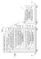
- FIG. 7 illustrates the flowchart of the cooperative travel control between the master tractor 1 P and the slave tractor 1 C that is executed in the U-turn work area A
- FIG. 8 illustrates traveling tracks of both tractors at that time
- FIGS. 9 to 14 are schematic diagrams illustrating travel patterns of the master tractor 1 P and the slave tractor 1 C that are executed in the loop work area B.
- initialization processing is performed first (# 10 ).
- the U-turn work area A in which cultivation work is to be performed while the straight work traveling and U-turns are repeatedly performed, and the loop work area B in the perimeter of the U-turn work area A are set and recorded, based on, for example, the shape of an agricultural field in which cultivation work is to be performed.
- the loop work area B is used also as an area for non-working U-turn traveling performed at the time of cultivation work with respect to the U-turn work area A.
- the U-turn work area A is simply referred to also as a central area A since the U-turn work area A is commonly located in the center of an agricultural field
- the loop work area B is simply referred to also as a peripheral area B since the loop work area B is located near the periphery of the agricultural field.
- the work traveling (substantially straight traveling) of the master tractor 1 P is started in the central area A (# 11 ). After a predetermined time, the follow work traveling of the slave tractor 1 C is started (# 12 ). Accordingly, cooperative cultivation work with the work width by the master tractor 1 P and the work width by the slave tractor 1 C is performed. Then, when the master tractor 1 P arrives at the peripheral area B as shown in FIG. 8 , the cultivation apparatus 5 is raised, and the U-turn traveling of the master tractor 1 P is started (# 21 ). The position of the master tractor 1 P at that time is recorded as a master U-turn start point P 1 (# 22 ).
- the cultivation apparatus 5 is lowered and the work traveling of the master tractor 1 P is restarted (# 23 ).
- the position of the master tractor 1 P at that time is recorded as a master U-turn end point P 2 (# 24 ).
- a slave U-turn start point Q 1 and a slave U-turn end point Q 2 of the slave tractor 1 C are calculated.
- the slave U-turn start point Q 1 is a position that is shifted from the master U-turn start point P 1 with consideration given to a distance in the lateral direction between the master tractor 1 P and the slave tractor 1 C and an amount of overlap therebetween.
- the slave U-turn end point Q 2 is a position between the master U-turn end point P 2 and the slave U-turn start point Q 1 , and is assumed to be an intermediate position in, for example, FIG. 8 .
- the positional relationship between the master U-turn start point P 1 /the master U-turn end point P 2 , and the slave U-turn start point Q 1 /the slave U-turn end point Q 2 is exactly opposite, and the slave U-turn end point Q 2 is a position located further outward than the master U-turn end point P 2 , and is obtained based on the cultivation widths of the master tractor 1 P and the slave tractor 1 C and the amount of overlap therebetween.
- a slave U-turn traveling route from the slave U-turn start point Q 1 toward the slave U-turn end point Q 2 is calculated (# 25 ). Furthermore, the position at which the slave tractor 1 C has almost reached an orientation in the work traveling direction before the slave U-turn end point Q 2 is calculated as a follow start point Qs (# 26 ). That is, the follow start point Qs is a position at which following the master tractor 1 P is started, so that the work traveling track of the slave tractor 1 C starting from the U-turn end point Q 2 exactly corresponds to the work traveling track of the master tractor 1 P.
- a stop point Pc 0 of the slave tractor 1 C and the redirection traveling start point Pp 1 , which serves as a stop point of the master tractor 1 P, at the start of the cooperation control in the loop work in the peripheral area B are stop points at the ends of the cultivation work in the central area A.
- the work width in the peripheral area B corresponds to the width obtained by three tractors, and requires two rounds of loop work traveling of the master tractor 1 P and one round of loop work traveling of the slave tractor 1 C.
- the master tractor 1 P travels forward while turning to the redirection point Pp 2 in an outermost work width zone with its cultivation apparatus 5 raised (in the non-working state), and then travels backward substantially straight so as to arrive at the redirection traveling end point Pp 3 (see FIG. 10 ). Since this redirection traveling end point Pp 3 is the start point of the loop work traveling, the master tractor 1 P lowers the cultivation apparatus 5 (in the working state) here and travels forward, starting the straight loop work traveling.
- the redirection traveling of the slave tractor 1 C needs to be started after the master tractor 1 P passes by the front of the slave tractor 1 C, in order to prevent interfering with the master tractor 1 P, but during this, the redirection traveling start point Pc 1 , the redirection point Pc 2 , which serves as a target of the redirection traveling, and the redirection traveling end point Pc 3 of the slave tractor 1 C are calculated (see FIG. 12 ).
- the travel of the slave tractor 1 C to the redirection traveling start point Pc 1 is the same as the work traveling for following the master tractor 1 P in the central area A, and thus when there is no interference with the master tractor 1 P, the slave tractor 1 C travels forward to the redirection traveling start point Pc 1 , where the slave tractor 1 C raises the cultivation apparatus 5 and stands by.
- a method for calculating the redirection point Pc 2 and the redirection traveling end point Pc 3 , which serve as targets for the redirection traveling of the slave tractor 1 C, will be described with reference to FIG. 11 .
- a line obtained by translating the traveling track of the master tractor 1 P from the position at which the master tractor 1 P lowered the cultivation apparatus 5 , that is, the loop work traveling start point (redirection traveling end point) Pp 3 by a distance that is half of the work width of the master tractor 1 P and the slave tractor 1 C is calculated as a redirection auxiliary line.
- the cross point between this redirection auxiliary line and the outer edge of the loop work area B is the redirection traveling end point Pc 3 of the slave tractor 1 C.
- the position at which the slave tractor 1 C arrives at the redirection auxiliary line from the redirection traveling start point Pc 1 of the slave tractor 1 C at a steering angle for redirection turning is calculated as the redirection point Pc 2 .
- the slave tractor 1 C travels forward while turning from the redirection traveling start point Pc 1 to the redirection point Pc 2 in the non-working state in which the cultivation apparatus 5 is raised, and then travels backward from the redirection point Pc 2 to the redirection traveling end point Pc 3 . This backward traveling is performed straight toward the redirection traveling end point Pc 3 serving as the target traveling position.
- the slave tractor 1 C lowers the cultivation apparatus 5 at this position, and performs loop work traveling while following the master tractor 1 P in the working state, based on the target traveling position that was calculated based on the traveling track of the master tractor 1 P.
- the master tractor 1 P travels backward to the redirection traveling start point Pp 1 in the non-working state in which the cultivation apparatus 5 is raised. From here, the second redirection traveling is started. In other words, the master tractor 1 P travels forward while turning from this redirection traveling start point Pp 1 to the redirection point Pp 2 in the non-working state. Then, the master tractor 1 P travels backward to the outer edge of the loop work area B, and is stopped. Since this stop point serves as the start point of the next loop work traveling, the master tractor 1 P starts forward traveling in the working state in which the cultivation apparatus 5 is lowered.
- a line that is obtained by translating the traveling track of the forward traveling (loop work traveling) of this master tractor 1 P by a distance that is half of the work width of the master tractor 1 P and the slave tractor 1 C is calculated, as the redirection auxiliary line here, and the redirection point Pc 2 on this redirection auxiliary line is calculated.
- the redirection traveling start point Pc 1 from which the slave tractor 1 C can arrive at the redirection point Pc 2 at a steering angle for redirection turning is calculated.
- the slave tractor 1 C stands by until the master tractor 1 P arrives at a predetermined point, in order to be prevented from interfering with the master tractor 1 P during the redirection traveling. Then, as shown in FIG. 14 , the slave tractor 1 C remains in the working state and travels as close to the outer edge of the loop work area B as possible beyond the redirection traveling start point. Then, the slave tractor 1 C travels backward to the redirection traveling start point Pc 1 in the non-working state in which the cultivation apparatus 5 is raised.
- the redirection traveling from the redirection traveling start point Pc 1 is such that the slave tractor 1 C travels forward while turning to the redirection point Pp 2 , similarly to the last redirection traveling. Then, the slave tractor 1 C travels backward to the outer edge of the loop work area B, and is stopped.
- the slave tractor 1 C travels forward in the working state in which the cultivation apparatus 5 is lowered.
- the slave tractor 1 C will first exit from the agricultural field because the non-working ground of the loop work area B can be covered only by the master tractor 1 P in this example.
- the present invention is applicable to a plurality of slave tractors 1 C using a similar control method.
- two following control methods are possible.
- a first slave tractor 1 C is controlled to follow the track of the master tractor 1 P with consideration given to the work width of the master tractor 1 P
- a second slave tractor 1 C is controlled to follow the track of the master tractor 1 P with consideration given to the work width of the first slave tractor 1 C as well.
- the first slave tractor 1 C is controlled to follow the track of the master tractor 1 P
- the second slave tractor 1 C is controlled to follow the first slave tractor 1 C serving as the master tractor 1 P. That is, in the case where there are a plurality of slave tractors 1 C, following control in which the preceding slave tractor 1 C serves as the master tractor 1 P is also possible.
- the redirection traveling tracks of the master tractor 1 P and the slave tractor 1 C are not limited to the above-described traveling tracks of the embodiment. It is possible to employ various redirection traveling tracks that include the redirection traveling start point Pc 1 , the redirection point Pc 2 , and the redirection traveling end point Pc 3 of the slave tractor 1 C that can be calculated based on the work width of the master tractor 1 P and the work width of the slave tractor 1 C, and the redirection traveling track of the redirection traveling of the master tractor 1 P, the redirection traveling track including the redirection traveling start point Pp 1 , the redirection point Pp 2 , and the redirection traveling end point Pp 3 . Furthermore, there may be one or more redirection points Pp 2 and Pc 2 of the master tractor 1 P and the slave tractor 1 C, respectively.
- the master tractor 1 P is of a manned-navigation type, but this master tractor 1 P may be operated in an unmanned manner by employing a program control method or a remote-control method.
- the present invention is applicable to a form in which the master tractor 1 P, that is, the master work vehicle is also operated in an unmanned manner.
- the tractor on which the cultivation apparatus 5 is mounted is given as an example of a work vehicle
- the characteristics of the present invention can be used advantageously even in the case where instead of the cultivation apparatus 5 , another working apparatus such as a sprinkling apparatus or a fertilizing apparatus is mounted.
- the present invention is also applicable to another work vehicle, such as, civil engineering and construction machinery, for example, a combine, a rice-planting machine, a lawnmower, a weeding machine, or a bulldozer.
- the master work vehicle and the slave work vehicle do not necessarily need to be of the same type, and a combination of, for example, a combine and a conveying truck, or the like is also possible.
- the present invention is applicable to a cooperation control system in which a plurality of work vehicles perform work traveling in cooperation with each other.
Landscapes
- Engineering & Computer Science (AREA)
- Radar, Positioning & Navigation (AREA)
- Remote Sensing (AREA)
- Physics & Mathematics (AREA)
- Automation & Control Theory (AREA)
- General Physics & Mathematics (AREA)
- Aviation & Aerospace Engineering (AREA)
- Life Sciences & Earth Sciences (AREA)
- Environmental Sciences (AREA)
- Soil Sciences (AREA)
- Mechanical Engineering (AREA)
- Guiding Agricultural Machines (AREA)
- Control Of Position, Course, Altitude, Or Attitude Of Moving Bodies (AREA)
- Business, Economics & Management (AREA)
- Health & Medical Sciences (AREA)
- Artificial Intelligence (AREA)
- Evolutionary Computation (AREA)
- Game Theory and Decision Science (AREA)
- Medical Informatics (AREA)
Applications Claiming Priority (3)
| Application Number | Priority Date | Filing Date | Title |
|---|---|---|---|
| JP2014-067006 | 2014-03-27 | ||
| JP2014067006A JP6189779B2 (ja) | 2014-03-27 | 2014-03-27 | 作業車協調システム |
| PCT/JP2015/058227 WO2015146778A1 (fr) | 2014-03-27 | 2015-03-19 | Système de coopération pour véhicule de travail |
Publications (2)
| Publication Number | Publication Date |
|---|---|
| US20160109885A1 US20160109885A1 (en) | 2016-04-21 |
| US9448561B2 true US9448561B2 (en) | 2016-09-20 |
Family
ID=54195299
Family Applications (1)
| Application Number | Title | Priority Date | Filing Date |
|---|---|---|---|
| US14/774,288 Active US9448561B2 (en) | 2014-03-27 | 2015-03-19 | Work vehicle cooperation system |
Country Status (4)
| Country | Link |
|---|---|
| US (1) | US9448561B2 (fr) |
| EP (1) | EP3123849B1 (fr) |
| JP (1) | JP6189779B2 (fr) |
| WO (1) | WO2015146778A1 (fr) |
Cited By (4)
| Publication number | Priority date | Publication date | Assignee | Title |
|---|---|---|---|---|
| US10551832B2 (en) | 2017-08-29 | 2020-02-04 | Cnh Industrial America Llc | Method and system for transporting an autonomous agricultural vehicle |
| US20220121202A1 (en) * | 2020-10-16 | 2022-04-21 | Mtd Products Inc | Power equipment device with driver-assisted semi-autonomous operation |
| US11999379B2 (en) | 2021-08-05 | 2024-06-04 | Cnh Industrial America Llc | Systems and methods for controlling a work vehicle |
| US12269528B2 (en) | 2019-09-09 | 2025-04-08 | Mtd Products Inc | Real time kinematics power equipment device with auto-steering |
Families Citing this family (21)
| Publication number | Priority date | Publication date | Assignee | Title |
|---|---|---|---|---|
| JP6301702B2 (ja) * | 2014-03-27 | 2018-03-28 | 株式会社クボタ | 作業車協調システム |
| JP6219790B2 (ja) * | 2014-07-29 | 2017-10-25 | 株式会社クボタ | 作業車協調システム |
| JP6594805B2 (ja) * | 2016-03-11 | 2019-10-23 | ヤンマー株式会社 | 作業車両 |
| JP6499605B2 (ja) * | 2016-03-17 | 2019-04-10 | ヤンマー株式会社 | 走行領域特定装置 |
| JP6605375B2 (ja) * | 2016-03-17 | 2019-11-13 | ヤンマー株式会社 | 自律走行作業車両 |
| AU2017231273A1 (en) * | 2016-03-09 | 2018-10-11 | Yanmar Co., Ltd. | Work vehicle and travel region specifying device |
| CN109074081A (zh) * | 2016-05-10 | 2018-12-21 | 洋马株式会社 | 自主行驶路径生成系统 |
| JP6832828B2 (ja) * | 2016-10-26 | 2021-02-24 | 株式会社クボタ | 走行経路決定装置 |
| WO2018116771A1 (fr) * | 2016-12-19 | 2018-06-28 | 株式会社クボタ | Dispositif de détermination de trajet de déplacement |
| JP6659630B2 (ja) * | 2017-08-02 | 2020-03-04 | 株式会社クボタ | 作業車協調システム |
| US11042162B2 (en) | 2018-09-13 | 2021-06-22 | Cnh Industrial Canada, Ltd. | System and method for determining work routes for agricultural vehicles |
| CN109165631A (zh) * | 2018-09-20 | 2019-01-08 | 黑龙江惠达科技发展有限公司 | 一种基于农机行驶轨迹的垄线识别及作业面积计算方法 |
| US11178712B2 (en) * | 2018-10-02 | 2021-11-16 | Deere & Company | Systems and methods to establish secure vehicle networks |
| CN109724803A (zh) * | 2019-01-02 | 2019-05-07 | 广西玉柴机器股份有限公司 | 拖拉机带旋耕机的便携式排放测试系统的测试方法及装置 |
| JP6886626B2 (ja) * | 2019-04-15 | 2021-06-16 | ヤンマーパワーテクノロジー株式会社 | 作業車両の走行領域登録システム |
| JP7260412B2 (ja) * | 2019-06-20 | 2023-04-18 | ヤンマーパワーテクノロジー株式会社 | 作業車両用の自動走行システム |
| JP7458311B2 (ja) * | 2020-12-15 | 2024-03-29 | ヤンマーホールディングス株式会社 | 自動走行システム、自動走行方法、及び自動走行プログラム |
| AU2023226142B2 (en) * | 2022-02-25 | 2026-04-09 | Raven Industries, Inc. | Dynamic guidance system for accompanying vehicle and methods for same |
| JP7580423B2 (ja) * | 2022-04-22 | 2024-11-11 | 株式会社小松製作所 | 作業現場の管理システム及び作業現場の管理方法 |
| WO2023211775A1 (fr) * | 2022-04-29 | 2023-11-02 | Carbon Autonomous Robotic Systems Inc. | Système et procédé de navigation autonome dans un champ |
| NL2034914B1 (en) * | 2023-05-25 | 2024-12-05 | Lely Patent Nv | Method of repeatedly working a field by means of an unmanned, self-propelled agricultural vehicle and unmanned, self-propelled agricultural vehicle configured to perform the method |
Citations (15)
| Publication number | Priority date | Publication date | Assignee | Title |
|---|---|---|---|---|
| JPH1066405A (ja) | 1996-08-28 | 1998-03-10 | Seibutsukei Tokutei Sangyo Gijutsu Kenkyu Suishin Kiko | 作業車両の無人走行による無人作業方法 |
| JPH1139036A (ja) | 1997-07-23 | 1999-02-12 | Kubota Corp | 作業車の走行制御装置 |
| JPH11266608A (ja) | 1998-03-23 | 1999-10-05 | Bio Oriented Technol Res Advancement Inst | 圃場作業車両の無人作業方法 |
| JP2000014208A (ja) | 1998-07-03 | 2000-01-18 | Bio Oriented Technol Res Advancement Inst | 圃場作業車両の運行支援装置 |
| US6148255A (en) | 1997-10-08 | 2000-11-14 | Massland N.V. A Dutch Limited Company | Vehicle combination |
| US6732024B2 (en) | 2001-05-07 | 2004-05-04 | The Board Of Trustees Of The Leland Stanford Junior University | Method and apparatus for vehicle control, navigation and positioning |
| US20080119965A1 (en) * | 2006-11-17 | 2008-05-22 | Mccrary Homer T | Intelligent Public Transit System Using Dual-Mode Vehicles |
| US20100312428A1 (en) * | 2003-03-20 | 2010-12-09 | Roberge Andre C | Gnss guidance and machine control |
| US20110112730A1 (en) | 2009-11-12 | 2011-05-12 | Deere & Company | Coordination of vehicle movement in a field |
| US8154227B1 (en) * | 2003-11-26 | 2012-04-10 | Liontech Trains Llc | Model train control system |
| US20120215410A1 (en) * | 2003-03-20 | 2012-08-23 | Mcclure John A | Gnss based control for dispensing material from vehicle |
| US20130213518A1 (en) * | 2012-02-10 | 2013-08-22 | Deere & Company | Method and stereo vision system for facilitating the unloading of agricultural material from a vehicle |
| US20140224377A1 (en) * | 2013-02-08 | 2014-08-14 | Deere & Company | Method and stereo vision system for facilitating the unloading of agricultural material from a vehicle |
| US20140324291A1 (en) * | 2003-03-20 | 2014-10-30 | Agjunction Llc | Gnss and optical guidance and machine control |
| US20150286218A1 (en) * | 2014-04-08 | 2015-10-08 | Unitronics Parking Solutions Ltd | System and method for tracking guiding lines by an autonomous vehicle |
Family Cites Families (1)
| Publication number | Priority date | Publication date | Assignee | Title |
|---|---|---|---|---|
| DE102006015204A1 (de) * | 2006-03-30 | 2007-10-18 | Claas Selbstfahrende Erntemaschinen Gmbh | Verfahren zur Erstellung eines Routenplans für landwirtschaftliche Maschinensysteme |
-
2014
- 2014-03-27 JP JP2014067006A patent/JP6189779B2/ja active Active
-
2015
- 2015-03-19 US US14/774,288 patent/US9448561B2/en active Active
- 2015-03-19 EP EP15769262.5A patent/EP3123849B1/fr active Active
- 2015-03-19 WO PCT/JP2015/058227 patent/WO2015146778A1/fr not_active Ceased
Patent Citations (16)
| Publication number | Priority date | Publication date | Assignee | Title |
|---|---|---|---|---|
| JPH1066405A (ja) | 1996-08-28 | 1998-03-10 | Seibutsukei Tokutei Sangyo Gijutsu Kenkyu Suishin Kiko | 作業車両の無人走行による無人作業方法 |
| JPH1139036A (ja) | 1997-07-23 | 1999-02-12 | Kubota Corp | 作業車の走行制御装置 |
| US6148255A (en) | 1997-10-08 | 2000-11-14 | Massland N.V. A Dutch Limited Company | Vehicle combination |
| JP2001507843A (ja) | 1997-10-08 | 2001-06-12 | マースランド エヌ・ヴィ | 車両の組合わせ |
| JPH11266608A (ja) | 1998-03-23 | 1999-10-05 | Bio Oriented Technol Res Advancement Inst | 圃場作業車両の無人作業方法 |
| JP2000014208A (ja) | 1998-07-03 | 2000-01-18 | Bio Oriented Technol Res Advancement Inst | 圃場作業車両の運行支援装置 |
| US6732024B2 (en) | 2001-05-07 | 2004-05-04 | The Board Of Trustees Of The Leland Stanford Junior University | Method and apparatus for vehicle control, navigation and positioning |
| US20100312428A1 (en) * | 2003-03-20 | 2010-12-09 | Roberge Andre C | Gnss guidance and machine control |
| US20120215410A1 (en) * | 2003-03-20 | 2012-08-23 | Mcclure John A | Gnss based control for dispensing material from vehicle |
| US20140324291A1 (en) * | 2003-03-20 | 2014-10-30 | Agjunction Llc | Gnss and optical guidance and machine control |
| US8154227B1 (en) * | 2003-11-26 | 2012-04-10 | Liontech Trains Llc | Model train control system |
| US20080119965A1 (en) * | 2006-11-17 | 2008-05-22 | Mccrary Homer T | Intelligent Public Transit System Using Dual-Mode Vehicles |
| US20110112730A1 (en) | 2009-11-12 | 2011-05-12 | Deere & Company | Coordination of vehicle movement in a field |
| US20130213518A1 (en) * | 2012-02-10 | 2013-08-22 | Deere & Company | Method and stereo vision system for facilitating the unloading of agricultural material from a vehicle |
| US20140224377A1 (en) * | 2013-02-08 | 2014-08-14 | Deere & Company | Method and stereo vision system for facilitating the unloading of agricultural material from a vehicle |
| US20150286218A1 (en) * | 2014-04-08 | 2015-10-08 | Unitronics Parking Solutions Ltd | System and method for tracking guiding lines by an autonomous vehicle |
Cited By (6)
| Publication number | Priority date | Publication date | Assignee | Title |
|---|---|---|---|---|
| US10551832B2 (en) | 2017-08-29 | 2020-02-04 | Cnh Industrial America Llc | Method and system for transporting an autonomous agricultural vehicle |
| US12269528B2 (en) | 2019-09-09 | 2025-04-08 | Mtd Products Inc | Real time kinematics power equipment device with auto-steering |
| US12668304B2 (en) | 2019-09-09 | 2026-06-30 | Mtd Products Inc | Correction of real time kinematics position location data for semi-automated steering of a power equipment device |
| US20220121202A1 (en) * | 2020-10-16 | 2022-04-21 | Mtd Products Inc | Power equipment device with driver-assisted semi-autonomous operation |
| US12530028B2 (en) * | 2020-10-16 | 2026-01-20 | Mtd Products Inc | Power equipment device with driver-assisted semi-autonomous operation |
| US11999379B2 (en) | 2021-08-05 | 2024-06-04 | Cnh Industrial America Llc | Systems and methods for controlling a work vehicle |
Also Published As
| Publication number | Publication date |
|---|---|
| JP6189779B2 (ja) | 2017-08-30 |
| JP2015188350A (ja) | 2015-11-02 |
| WO2015146778A1 (fr) | 2015-10-01 |
| EP3123849A4 (fr) | 2017-12-06 |
| US20160109885A1 (en) | 2016-04-21 |
| EP3123849A1 (fr) | 2017-02-01 |
| EP3123849B1 (fr) | 2022-05-11 |
Similar Documents
| Publication | Publication Date | Title |
|---|---|---|
| EP3123849B1 (fr) | Système de coopération pour véhicule de travail | |
| US9839174B2 (en) | Work vehicle cooperation system | |
| EP2784617B1 (fr) | Système de coordination de véhicules de travail | |
| EP3176665B1 (fr) | Système de coopération pour véhicules de travail | |
| KR102534336B1 (ko) | 경로 생성 시스템 | |
| JP6673862B2 (ja) | 走行経路特定システム | |
| JP2017173969A (ja) | 自律走行システム | |
| WO2018047500A1 (fr) | Système de déplacement autonome | |
| JP6659630B2 (ja) | 作業車協調システム | |
| JP6385412B2 (ja) | 作業車協調システム | |
| JP7094832B2 (ja) | 協調作業システム | |
| JP6621724B2 (ja) | 経路生成システム | |
| JP2021061015A (ja) | 経路生成システム | |
| JP6945689B2 (ja) | 作業車 | |
| JP2018041359A (ja) | 自律走行システム | |
| JP6945353B2 (ja) | 自動走行作業車 | |
| JP7004756B2 (ja) | 作業車協調システム | |
| JP6723275B2 (ja) | 作業車協調システム | |
| JP6860640B2 (ja) | 経路生成システム | |
| JP2020095744A (ja) | 走行経路特定システム |
Legal Events
| Date | Code | Title | Description |
|---|---|---|---|
| AS | Assignment |
Owner name: KUBOTA CORPORATION, JAPAN Free format text: ASSIGNMENT OF ASSIGNORS INTEREST;ASSIGNORS:FUJIMOTO, YOSHITOMO;ARAKI, HIROYUKI;UOYA, YASUHISA;REEL/FRAME:036531/0637 Effective date: 20150805 |
|
| STCF | Information on status: patent grant |
Free format text: PATENTED CASE |
|
| CC | Certificate of correction | ||
| MAFP | Maintenance fee payment |
Free format text: PAYMENT OF MAINTENANCE FEE, 4TH YEAR, LARGE ENTITY (ORIGINAL EVENT CODE: M1551); ENTITY STATUS OF PATENT OWNER: LARGE ENTITY Year of fee payment: 4 |
|
| MAFP | Maintenance fee payment |
Free format text: PAYMENT OF MAINTENANCE FEE, 8TH YEAR, LARGE ENTITY (ORIGINAL EVENT CODE: M1552); ENTITY STATUS OF PATENT OWNER: LARGE ENTITY Year of fee payment: 8 |