US9456725B2 - Robot cleaner and control method thereof - Google Patents
Robot cleaner and control method thereof Download PDFInfo
- Publication number
- US9456725B2 US9456725B2 US13/373,192 US201113373192A US9456725B2 US 9456725 B2 US9456725 B2 US 9456725B2 US 201113373192 A US201113373192 A US 201113373192A US 9456725 B2 US9456725 B2 US 9456725B2
- Authority
- US
- United States
- Prior art keywords
- area
- rpm
- robot cleaner
- main brush
- control unit
- Prior art date
- Legal status (The legal status is an assumption and is not a legal conclusion. Google has not performed a legal analysis and makes no representation as to the accuracy of the status listed.)
- Expired - Fee Related, expires
Links
Images




Classifications
-
- A—HUMAN NECESSITIES
- A47—FURNITURE; DOMESTIC ARTICLES OR APPLIANCES; COFFEE MILLS; SPICE MILLS; SUCTION CLEANERS IN GENERAL
- A47L—DOMESTIC WASHING OR CLEANING; SUCTION CLEANERS IN GENERAL
- A47L9/00—Details or accessories of suction cleaners, e.g. mechanical means for controlling the suction or for effecting pulsating action; Storing devices specially adapted to suction cleaners or parts thereof; Carrying-vehicles specially adapted for suction cleaners
- A47L9/28—Installation of the electric equipment, e.g. adaptation or attachment to the suction cleaner; Controlling suction cleaners by electric means
- A47L9/2805—Parameters or conditions being sensed
- A47L9/2826—Parameters or conditions being sensed the condition of the floor
-
- A—HUMAN NECESSITIES
- A47—FURNITURE; DOMESTIC ARTICLES OR APPLIANCES; COFFEE MILLS; SPICE MILLS; SUCTION CLEANERS IN GENERAL
- A47L—DOMESTIC WASHING OR CLEANING; SUCTION CLEANERS IN GENERAL
- A47L9/00—Details or accessories of suction cleaners, e.g. mechanical means for controlling the suction or for effecting pulsating action; Storing devices specially adapted to suction cleaners or parts thereof; Carrying-vehicles specially adapted for suction cleaners
- A47L9/28—Installation of the electric equipment, e.g. adaptation or attachment to the suction cleaner; Controlling suction cleaners by electric means
-
- A—HUMAN NECESSITIES
- A47—FURNITURE; DOMESTIC ARTICLES OR APPLIANCES; COFFEE MILLS; SPICE MILLS; SUCTION CLEANERS IN GENERAL
- A47L—DOMESTIC WASHING OR CLEANING; SUCTION CLEANERS IN GENERAL
- A47L9/00—Details or accessories of suction cleaners, e.g. mechanical means for controlling the suction or for effecting pulsating action; Storing devices specially adapted to suction cleaners or parts thereof; Carrying-vehicles specially adapted for suction cleaners
- A47L9/28—Installation of the electric equipment, e.g. adaptation or attachment to the suction cleaner; Controlling suction cleaners by electric means
- A47L9/2805—Parameters or conditions being sensed
-
- A—HUMAN NECESSITIES
- A47—FURNITURE; DOMESTIC ARTICLES OR APPLIANCES; COFFEE MILLS; SPICE MILLS; SUCTION CLEANERS IN GENERAL
- A47L—DOMESTIC WASHING OR CLEANING; SUCTION CLEANERS IN GENERAL
- A47L9/00—Details or accessories of suction cleaners, e.g. mechanical means for controlling the suction or for effecting pulsating action; Storing devices specially adapted to suction cleaners or parts thereof; Carrying-vehicles specially adapted for suction cleaners
- A47L9/28—Installation of the electric equipment, e.g. adaptation or attachment to the suction cleaner; Controlling suction cleaners by electric means
- A47L9/2805—Parameters or conditions being sensed
- A47L9/2831—Motor parameters, e.g. motor load or speed
-
- A—HUMAN NECESSITIES
- A47—FURNITURE; DOMESTIC ARTICLES OR APPLIANCES; COFFEE MILLS; SPICE MILLS; SUCTION CLEANERS IN GENERAL
- A47L—DOMESTIC WASHING OR CLEANING; SUCTION CLEANERS IN GENERAL
- A47L9/00—Details or accessories of suction cleaners, e.g. mechanical means for controlling the suction or for effecting pulsating action; Storing devices specially adapted to suction cleaners or parts thereof; Carrying-vehicles specially adapted for suction cleaners
- A47L9/28—Installation of the electric equipment, e.g. adaptation or attachment to the suction cleaner; Controlling suction cleaners by electric means
- A47L9/2836—Installation of the electric equipment, e.g. adaptation or attachment to the suction cleaner; Controlling suction cleaners by electric means characterised by the parts which are controlled
- A47L9/2847—Surface treating elements
-
- A—HUMAN NECESSITIES
- A47—FURNITURE; DOMESTIC ARTICLES OR APPLIANCES; COFFEE MILLS; SPICE MILLS; SUCTION CLEANERS IN GENERAL
- A47L—DOMESTIC WASHING OR CLEANING; SUCTION CLEANERS IN GENERAL
- A47L9/00—Details or accessories of suction cleaners, e.g. mechanical means for controlling the suction or for effecting pulsating action; Storing devices specially adapted to suction cleaners or parts thereof; Carrying-vehicles specially adapted for suction cleaners
- A47L9/28—Installation of the electric equipment, e.g. adaptation or attachment to the suction cleaner; Controlling suction cleaners by electric means
- A47L9/2836—Installation of the electric equipment, e.g. adaptation or attachment to the suction cleaner; Controlling suction cleaners by electric means characterised by the parts which are controlled
- A47L9/2852—Elements for displacement of the vacuum cleaner or the accessories therefor, e.g. wheels, casters or nozzles
-
- A—HUMAN NECESSITIES
- A47—FURNITURE; DOMESTIC ARTICLES OR APPLIANCES; COFFEE MILLS; SPICE MILLS; SUCTION CLEANERS IN GENERAL
- A47L—DOMESTIC WASHING OR CLEANING; SUCTION CLEANERS IN GENERAL
- A47L9/00—Details or accessories of suction cleaners, e.g. mechanical means for controlling the suction or for effecting pulsating action; Storing devices specially adapted to suction cleaners or parts thereof; Carrying-vehicles specially adapted for suction cleaners
- A47L9/28—Installation of the electric equipment, e.g. adaptation or attachment to the suction cleaner; Controlling suction cleaners by electric means
- A47L9/2857—User input or output elements for control, e.g. buttons, switches or displays
-
- G—PHYSICS
- G05—CONTROLLING; REGULATING
- G05D—SYSTEMS FOR CONTROLLING OR REGULATING NON-ELECTRIC VARIABLES
- G05D1/00—Control of position, course, altitude or attitude of land, water, air or space vehicles, e.g. using automatic pilots
- G05D1/02—Control of position or course in two dimensions
- G05D1/021—Control of position or course in two dimensions specially adapted to land vehicles
- G05D1/0268—Control of position or course in two dimensions specially adapted to land vehicles using internal positioning means
- G05D1/0274—Control of position or course in two dimensions specially adapted to land vehicles using internal positioning means using mapping information stored in a memory device
-
- G—PHYSICS
- G05—CONTROLLING; REGULATING
- G05D—SYSTEMS FOR CONTROLLING OR REGULATING NON-ELECTRIC VARIABLES
- G05D1/00—Control of position, course, altitude or attitude of land, water, air or space vehicles, e.g. using automatic pilots
- G05D1/60—Intended control result
- G05D1/644—Optimisation of travel parameters, e.g. of energy consumption, journey time or distance
-
- G—PHYSICS
- G05—CONTROLLING; REGULATING
- G05D—SYSTEMS FOR CONTROLLING OR REGULATING NON-ELECTRIC VARIABLES
- G05D1/00—Control of position, course, altitude or attitude of land, water, air or space vehicles, e.g. using automatic pilots
- G05D1/60—Intended control result
- G05D1/648—Performing a task within a working area or space, e.g. cleaning
-
- A—HUMAN NECESSITIES
- A47—FURNITURE; DOMESTIC ARTICLES OR APPLIANCES; COFFEE MILLS; SPICE MILLS; SUCTION CLEANERS IN GENERAL
- A47L—DOMESTIC WASHING OR CLEANING; SUCTION CLEANERS IN GENERAL
- A47L2201/00—Robotic cleaning machines, i.e. with automatic control of the travelling movement or the cleaning operation
- A47L2201/02—Docking stations; Docking operations
-
- A—HUMAN NECESSITIES
- A47—FURNITURE; DOMESTIC ARTICLES OR APPLIANCES; COFFEE MILLS; SPICE MILLS; SUCTION CLEANERS IN GENERAL
- A47L—DOMESTIC WASHING OR CLEANING; SUCTION CLEANERS IN GENERAL
- A47L2201/00—Robotic cleaning machines, i.e. with automatic control of the travelling movement or the cleaning operation
- A47L2201/02—Docking stations; Docking operations
- A47L2201/022—Recharging of batteries
-
- A—HUMAN NECESSITIES
- A47—FURNITURE; DOMESTIC ARTICLES OR APPLIANCES; COFFEE MILLS; SPICE MILLS; SUCTION CLEANERS IN GENERAL
- A47L—DOMESTIC WASHING OR CLEANING; SUCTION CLEANERS IN GENERAL
- A47L2201/00—Robotic cleaning machines, i.e. with automatic control of the travelling movement or the cleaning operation
- A47L2201/04—Automatic control of the travelling movement; Automatic obstacle detection
-
- A—HUMAN NECESSITIES
- A47—FURNITURE; DOMESTIC ARTICLES OR APPLIANCES; COFFEE MILLS; SPICE MILLS; SUCTION CLEANERS IN GENERAL
- A47L—DOMESTIC WASHING OR CLEANING; SUCTION CLEANERS IN GENERAL
- A47L2201/00—Robotic cleaning machines, i.e. with automatic control of the travelling movement or the cleaning operation
- A47L2201/06—Control of the cleaning action for autonomous devices; Automatic detection of the surface condition before, during or after cleaning
-
- G—PHYSICS
- G05—CONTROLLING; REGULATING
- G05D—SYSTEMS FOR CONTROLLING OR REGULATING NON-ELECTRIC VARIABLES
- G05D1/00—Control of position, course, altitude or attitude of land, water, air or space vehicles, e.g. using automatic pilots
- G05D1/02—Control of position or course in two dimensions
- G05D1/021—Control of position or course in two dimensions specially adapted to land vehicles
- G05D1/0227—Control of position or course in two dimensions specially adapted to land vehicles using mechanical sensing means, e.g. for sensing treated area
-
- G—PHYSICS
- G05—CONTROLLING; REGULATING
- G05D—SYSTEMS FOR CONTROLLING OR REGULATING NON-ELECTRIC VARIABLES
- G05D1/00—Control of position, course, altitude or attitude of land, water, air or space vehicles, e.g. using automatic pilots
- G05D1/02—Control of position or course in two dimensions
- G05D1/021—Control of position or course in two dimensions specially adapted to land vehicles
- G05D1/0231—Control of position or course in two dimensions specially adapted to land vehicles using optical position detecting means
- G05D1/0242—Control of position or course in two dimensions specially adapted to land vehicles using optical position detecting means using non-visible light signals, e.g. IR or UV signals
-
- G—PHYSICS
- G05—CONTROLLING; REGULATING
- G05D—SYSTEMS FOR CONTROLLING OR REGULATING NON-ELECTRIC VARIABLES
- G05D1/00—Control of position, course, altitude or attitude of land, water, air or space vehicles, e.g. using automatic pilots
- G05D1/02—Control of position or course in two dimensions
- G05D1/021—Control of position or course in two dimensions specially adapted to land vehicles
- G05D1/0231—Control of position or course in two dimensions specially adapted to land vehicles using optical position detecting means
- G05D1/0246—Control of position or course in two dimensions specially adapted to land vehicles using optical position detecting means using a video camera in combination with image processing means
-
- G—PHYSICS
- G05—CONTROLLING; REGULATING
- G05D—SYSTEMS FOR CONTROLLING OR REGULATING NON-ELECTRIC VARIABLES
- G05D1/00—Control of position, course, altitude or attitude of land, water, air or space vehicles, e.g. using automatic pilots
- G05D1/02—Control of position or course in two dimensions
- G05D1/021—Control of position or course in two dimensions specially adapted to land vehicles
- G05D1/0255—Control of position or course in two dimensions specially adapted to land vehicles using acoustic signals, e.g. ultra-sonic singals
-
- G—PHYSICS
- G05—CONTROLLING; REGULATING
- G05D—SYSTEMS FOR CONTROLLING OR REGULATING NON-ELECTRIC VARIABLES
- G05D2105/00—Specific applications of the controlled vehicles
- G05D2105/10—Specific applications of the controlled vehicles for cleaning, vacuuming or polishing
-
- G05D2201/0203—
Definitions
- Embodiments of the present disclosure relate to a robot cleaner to perform a cleaning operation according to the material or state of a floor and a control method thereof.
- a robot cleaner automatically cleans an area to be cleaned by sucking up foreign substances, such as dust, from a floor while autonomously traveling about the area to be cleaned without user manipulation.
- the robot cleaner detects a distance from an object, such as furniture, office appliances and walls, present in the cleaning area using an infrared sensor, etc., to travel without collision with the obstacle based on detected information.
- Cleaning a given cleaning area using the robot cleaner means an operation in which the robot cleaner repeatedly travels in the cleaning area based on a preset traveling pattern to clean the area.
- the cleaning area in which the robot cleaner travels to perform a cleaning operation may have irregularity in the material or state of a floor.
- most European and American houses contain a soft floor, on which a carpet is spread and a hard floor such as a wooden floor (hereinafter, referred to as ‘H/F’) together.
- uniformly cleaning a given cleaning area using the robot cleaner may require variation in the number of cleaning operations (the number of traveling motions) or the intensity of cleaning according to the material or state of a floor.
- a user may desire to clean only a partial area rather than the entire area. For example, a user who mainly spends time in an area on which a carpet is spread (hereinafter, referred to as a ‘carpet area’) may judge that the carpet area has a greater necessity for cleaning than the H/F area and may desire to clean only the carpet area or repeatedly clean the carpet area.
- a method of allowing the robot cleaner to stay in a specific area to clean the specific area by making a virtual wall using, e.g., infrared signals from an infrared transmitter installed at a door or the entrance of a separated space, such as a corridor, or by installing an obstacle at a door or the entrance of a corridor has been adopted.
- the method of allowing the robot cleaner to stay in the specific area defined by the virtual wall requires a signal transmitter, such as the infrared transmitter, causing additional installation costs. Further, with this method, it is difficult to direct the robot cleaner to perfectly or repeatedly clean only the carpet area because the specific area is defined regardless of the material of a floor.
- the robot cleaner may frequently fail to, complete a cleaning or docking operation.
- a position of carpet fringes has been marked on a virtual map to prevent the robot cleaner from entering an area where the carpet fringes are present.
- a robot cleaner and a control method thereof in which a carpet mode to clean only a carpet area and an H/F mode to clean an H/F area excluding the carpet area are given based on detected information relating to the material of a floor (carpet or H/F), which enables partial cleaning with respect to a cleaning area selected by a user and adjustment in the number of cleaning operations (the number of traveling motions) or the intensity of cleaning according to the material of the floor.
- a robot cleaner includes a main brush to sweep or scatter dust off a floor, a main brush motor to rotate the main brush, a Revolution Per Minute (RPM) detector to detect an RPM of the main brush motor, and a control unit to determine a material or state of the floor according to the RPM of the main brush motor acquired by the RPM detector and control an operation of the robot cleaner based on the determined material or state of the floor.
- RPM Revolution Per Minute
- the robot cleaner may further include an input unit to select a cleaning mode from among a carpet mode to clean only a carpet area, a hard floor mode to clean only a hard floor area and an auto mode to clean both the carpet area and the hard floor area, and the control unit may control a cleaning operation of the robot cleaner based on the cleaning mode input by the input unit.
- the control unit may adjust the number of traveling motions of the robot cleaner or the RPM of the main brush motor based on the determined material of the floor.
- the control unit may determine that the robot cleaner is traveling in the carpet area if the RPM of the main brush motor is less than a preset RPM and may determine that the robot cleaner is traveling in the hard floor area if the RPM of the main brush motor is greater than the preset RPM.
- the control unit may determine that the robot cleaner passes a boundary between the carpet area and the hard floor area or a stepped area if rapid rising of the RPM of the main brush motor occurs.
- the control unit may determine that the robot cleaner having passed through the hard floor area enters the carpet area if the RPM of the main brush motor is less than the previous RPM before rapid rising of the RPM of the main brush motor occurs.
- the control unit may determine that the robot cleaner having passed through the carpet area enters the hard floor area if the RPM of the main brush motor is greater than the previous RPM before rapid rising of the RPM of the main brush motor occurs.
- the robot cleaner may further include an upward camera unit to capture an upward image perpendicular to a traveling direction of the robot cleaner, and the control unit may produce a map with respect to a cleaning area using the upward image acquired by the upward camera unit during implementation of the cleaning operation and may mark the carpet area, the hard floor area, the boundary and the stepped area on the map.
- the control unit may control the robot cleaner using the produced map so as to avoid the carpet area, the boundary or the stepped area when the robot cleaner returns to a docking station after completing the cleaning operation based on the cleaning mode.
- the robot cleaner may further include a display unit to display that the robot cleaner is traveling in any one of the carpet area and the hard floor area.
- a robot cleaner includes a main brush to sweep or scatter dust off a floor, a main brush motor to rotate the main brush, a detector to detect driving information of the main brush motor, and a control unit to produce a map indicating a material or state of the floor according to the driving information of the main brush motor acquired by the detector.
- the material of the floor may be sorted into a carpet and a hard floor, and a cleaning area may be sorted into a carpet area and a hard floor area.
- the robot cleaner may further include an input unit to select a cleaning mode according to the material of the floor, and the control unit may control the robot cleaner so as to perform a cleaning operation with respect to an area, the material of the floor of which corresponds to the input cleaning mode.
- the cleaning mode may include a carpet mode to clean only the carpet area, a hard floor mode to clean only the hard floor area and an auto mode to clean both the carpet area and the hard floor area.
- the detector may be an RPM detector to detect an RPM of the main brush motor.
- the control unit may determine that the robot cleaner is traveling in the carpet area if the RPM of the main brush motor is less than a preset RPM and may determine that the robot cleaner is traveling in the hard floor area if the RPM of the main brush motor is greater than the preset RPM.
- the control unit may determine that the robot cleaner passes a boundary between the carpet area and the hard floor area or a stepped area if rapid rising of the RPM of the main brush motor occurs.
- the control unit may determine that the robot cleaner having passed through the hard floor area enters the carpet area if the RPM of the main brush motor is less than the previous RPM before rapid rising of the RPM of the main brush motor occurs.
- the control unit may determine that the robot cleaner having passed through the carpet area enters the hard floor area if the RPM of the main brush motor is greater than the previous RPM before rapid rising of the RPM of the main brush motor occurs.
- the robot cleaner may further include an upward camera unit to capture an upward image perpendicular to a traveling direction of the robot cleaner, and the control unit may produce a map with respect to the cleaning area using the upward image acquired by the upward camera unit during implementation of the cleaning operation and may mark the carpet area, the hard floor area, the boundary and the stepped area on the map.
- the control unit may control the robot cleaner using the produced map so as to avoid the carpet area, the boundary and the stepped area when the robot cleaner returns to a docking station after completing the cleaning operation based on the cleaning mode.
- the detector may be a current detector to detect current passing through the main brush motor.
- a control method of a robot cleaner includes inputting any one of a plurality of cleaning modes depending on materials of a floor, determining a material or state of the floor according to driving information of a main brush motor, and performing a cleaning operation on an area, the material of the floor of which corresponds to the input cleaning mode and simultaneously producing a map indicating the area, in which the cleaning operation is performed, and the determined material or state of the floor.
- the material of the floor may be sorted into a carpet and a hard floor, and the cleaning area may be sorted into a carpet area and a hard floor area.
- the plurality of cleaning modes may include a carpet mode to clean only the carpet area, a hard floor mode to clean only the hard floor area and an auto mode to clean both the carpet area and the hard floor area.
- the driving information of the main brush motor may include an RPM of the main brush motor, and an area in which the robot cleaner is traveling may be marked as the carpet area on the map if the RPM of the main brush motor is less than a preset RPM and may be marked as the hard floor area on the map if the RPM of the main brush motor is greater than the preset RPM.
- the robot cleaner passes a boundary between the carpet area and the hard floor area or a stepped area if rapid rising of the RPM of the main brush motor occurs, and an area in which the robot cleaner is passing may be marked as the boundary or the stepped area on the map.
- the cleaning operation may be performed in such a manner that the number of traveling motions of the robot cleaner or the RPM of the main brush motor is adjusted according to the cleaning mode.
- the control method may further include returning the robot cleaner to a docking station after completing the cleaning operation based on the cleaning mode, and the robot cleaner may travel to avoid the carpet area and the stepped area using the map while returning to the docking station.
- the control method may further include returning the robot cleaner to a docking station after completing the cleaning operation based on the cleaning mode, and the robot cleaner may travel in a direction perpendicular to the boundary and the stepped area using the map while returning to the docking station.
- the control method may further include displaying that the robot cleaner is traveling in any one of the carpet area and the hard floor area.
- FIG. 1 is a perspective view illustrating configurations of a robot cleaner and a docking station in accordance with an embodiment of the present disclosure
- FIG. 2 is a bottom view of the robot cleaner in accordance with the embodiment of the present disclosure
- FIG. 3 is a control block diagram of the robot cleaner and the docking station in accordance with the embodiment of the present disclosure
- FIGS. 4A and 4B are graphs illustrating a relationship between the material/state of a floor and RPM of a main brush motor
- FIG. 5 is a view illustrating an example of a cleaning area in which all of a carpet area, an H/F area and a stepped area are present;
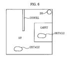
- FIG. 6 is a view illustrating a map produced as a result of the robot cleaner performing a carpet mode and a return traveling path using the produced map in accordance with an embodiment of the present disclosure
- FIG. 7 is a view illustrating a map produced as a result of the robot cleaner performing an H/F mode and a return traveling path using the produced map in accordance with an embodiment of the present disclosure
- FIG. 8 is a view illustrating a map produced as a result of the robot cleaner performing an auto mode and a return traveling path using the produced map in accordance with an embodiment of the present disclosure
- FIG. 9 is a view explaining an operation in which the robot cleaner assumes a boundary line and moves perpendicular to the assumed boundary line in accordance with an embodiment of the present disclosure.
- FIGS. 10A to 10C are flowcharts illustrating a control method of the robot cleaner in accordance with an embodiment of the present disclosure.
- FIG. 1 is a perspective view illustrating external configurations of a robot cleaner and a docking station in accordance with an embodiment of the present disclosure.
- the robot cleaner 100 in accordance with the embodiment of the present disclosure includes a main body 102 forming the external appearance of the robot cleaner 100 .
- the main body 102 is provided at a front upper position thereof with a receiver 105 , which receives an infrared signal or ultrasonic signal generated from transmitters 210 of a docking station 200 when the robot cleaner 100 returns to the docking station 200 .
- an input unit 120 including a plurality of buttons to input a cleaning or docking operation command, an upward camera unit 135 to capture an upward image perpendicular to a traveling direction and a display unit 180 to display information relating to operation of the robot cleaner 100 are arranged on the main body 102 .
- the input unit 120 includes the plurality of buttons, e.g., an ON/OFF button 125 to turn on or off power, a carpet mode button 121 to select a carpet mode to clean only a carpet area, an H/F mode button 122 to select an H/F mode to clean only an H/F area, an auto mode button 123 to select an auto mode to clean both the carpet area and the H/F area, and a start/pause button 124 to start or pause a cleaning or docking operation.
- buttons e.g., an ON/OFF button 125 to turn on or off power
- a carpet mode button 121 to select a carpet mode to clean only a carpet area
- an H/F mode button 122 to select an H/F mode to clean only an H/F area
- an auto mode button 123 to select an auto mode to clean both the carpet area and the H/F area
- a start/pause button 124 to start or pause a cleaning or docking operation.
- the display unit 180 includes a plurality of lights, e.g., a carpet area display light 181 to indicate that the robot cleaner 100 is cleaning (traveling) the carpet area and an H/F area display light 182 to indicate that the robot cleaner is cleaning (traveling) the H/F area. While the robot cleaner 100 passes a boundary between the carpet area and the H/F area, the carpet area display light 181 and the H/F area display light 182 are alternately turned on. In addition, the carpet area display light 181 and the H/F area display light 182 may be alternately turned on even while the robot cleaner 100 passes a stepped area, such as a doorsill or stairway.
- a carpet area display light 181 to indicate that the robot cleaner 100 is cleaning (traveling) the carpet area
- an H/F area display light 182 to indicate that the robot cleaner is cleaning (traveling) the H/F area. While the robot cleaner 100 passes a boundary between the carpet area and the H/F area, the carpet area display light 181 and the H/F area display light 18
- a bumper 103 to absorb shock generated upon collision with an obstacle is attached to a front portion of the main body 102 .
- An additional bumper 103 may further be attached to a rear portion of the main body 102 .
- An obstacle detector 140 is provided near the bumper 103 .
- the obstacle detector 140 is, for example, an ultrasonic sensor or an infrared sensor to sense an obstacle such as furniture and walls.
- the docking station 200 includes the transmitters 210 and charging terminals 220 .
- the transmitters 210 are arranged near a receptacle of the docking station 200 to transmit an infrared optical signal or ultrasonic signal so as to recognize that the robot cleaner 100 accesses the docking station 200 .
- the charging terminals 220 supply power to a battery (see 115 in FIG. 2 ) of the robot cleaner 100 when electrically connected to connection terminals (see 110 in FIG. 2 ) of the robot cleaner 100 .
- FIG. 2 is a bottom view of the robot cleaner in accordance with the embodiment of the present disclosure.
- the robot cleaner 100 includes elements 154 , 156 , 157 and 158 to move the robot cleaner 100 , elements 160 , 162 and 166 to sweep or scatter dust off a floor, and elements 110 and 115 to supply drive power to the robot cleaner 100 .
- the elements 154 , 156 , 157 and 158 to move the robot cleaner 100 include left and right wheels 157 and 158 arranged at opposite lateral positions of the main body 102 to enable forward and rearward movement and rotation of the robot cleaner 100 , wheel motors 156 to transmit power to the respective wheels 157 and 158 , and a caster wheel 154 arranged at a front position of the main body 102 and adapted to be rotated to change an orientation angle of the robot cleaner 100 according to the state of the floor on which the robot cleaner 100 travels.
- the caster wheel 154 further functions to support the robot cleaner 100 to stabilize posture of the robot cleaner 100 and prevent the robot cleaner 100 from falling over.
- the caster wheel 154 takes the form of a roller or a caster.
- the elements 160 , 162 and 166 to sweep or scatter dust off the floor include a main brush 160 provided at a suction opening 104 perforated in the bottom of the main body 102 , a main brush motor 166 to rotate the main brush 160 , and side brushes 162 provided at front positions of a lower surface of the main body 102 .
- the main brush 160 sweeps or scatters dust off the floor below the main body 102 , improving dust suction efficiency.
- the main brush 160 has a drum shape and consists of a roller and a brush.
- the side brushes 162 sweep dust on the floor in front of the main body 102 and an area where the main brush 160 cannot reach toward the suction opening 104 , improving dust suction efficiency.
- the robot cleaner 100 further includes a dust collection unit (not shown) provided near the main brush 160 to collect foreign substances, such as dust, collected by the main brush 160 .
- the robot cleaner 100 may collect foreign substances, such as dust, using suction force.
- the elements 110 and 115 to supply drive power to the robot cleaner 100 include the battery 115 to supply drive power to the wheel motors 156 , the main brush motor 166 and other drive units, and the connection terminals 110 electrically connected to the docking station 200 when the robot cleaner 100 docks with the docking station 200 .
- the battery 115 is a rechargeable secondary battery.
- the robot cleaner 100 is charged upon receiving power from the docking station 200 through the connection terminals 110 .
- FIG. 3 is a control block diagram of the robot cleaner and the docking station in accordance with the embodiment of the present disclosure.
- the robot cleaner 100 includes the receiver 105 , connection terminals 110 , input unit 120 , battery residue detector 130 , upward camera unit 135 , obstacle detector 140 , control unit 145 , storage unit 150 , wheel drive unit 155 , main brush drive unit 165 , current detector 170 , RPM detector 175 and display unit 180 .
- the receiver 105 receives an infrared optical signal or ultrasonic signal generated from the transmitters 210 of the docking station 200 and transmits information relating to the received signal to the control unit 145 .
- connection terminals 110 are connected to the charging terminals 220 of the docking station 200 to supply power to the battery 115 .
- the input unit 120 includes the plurality of buttons arranged on the main body 102 of the robot cleaner 100 or a remote controller, to allow a user to input a cleaning command (e.g., operation start/pause command) or a charging (docking) command of the robot cleaner 100 .
- the battery residue detector 130 detects remaining power of the battery 115 and transmits information relating to the remaining power to the control unit 145 .
- the upward camera unit 135 is installed on the main body 102 to capture an upward image perpendicular to a traveling direction and transmits the captured image to the control unit 145 .
- the upward camera unit 145 may be a charge coupled device (CCD) with a fish-eye lens.
- the obstacle detector 140 senses an obstacle, such as furniture, office appliances and walls, present in a cleaning area where the robot cleaner 100 travels.
- the obstacle detector 140 may be an ultrasonic sensor, which senses the presence or absence of an obstacle and a distance from the obstacle by emitting ultrasonic waves to a path along which the robot cleaner 100 travels and receives the ultrasonic waves reflected from the obstacle, or may be an infrared sensor which includes a plurality of infrared light emitting elements to emit infrared light and infrared light receiving elements to receive the infrared light reflected from the obstacle.
- the control unit 145 controls general operations of the robot cleaner 100 .
- the control unit 145 determines the material or state of the floor according to Revolution Per Minute (RPM) of the main brush motor 166 obtained by the RPM detector 175 or a current value of the main brush motor 166 obtained by the current detector 170 and makes a map to indicate the material or state of the floor.
- RPM Revolution Per Minute
- the control unit 145 receives any one of a plurality of cleaning modes (carpet mode, H/F mode and auto mode) according to the material of a floor from the input unit 120 . Thereby, the control unit 145 controls the robot cleaner 100 so as to perform a cleaning operation only with respect to an area, the floor material of which corresponds to the input cleaning mode.
- a plurality of cleaning modes carpet mode, H/F mode and auto mode
- the storage unit 150 stores preset traveling patterns, maps for the entire cleaning area made during traveling of the robot cleaner 100 , cleaning conditions according to cleaning modes (the number of traveling motions, RPM of the main brush motor, etc.).
- the wheel drive unit 155 includes the wheel motors 156 to rotate and drive the left and right wheels 157 and 158 provided at the bottom of the main body 102 .
- a rotation angle or traveling direction of the robot cleaner 100 is determined by differentiating RPM values of the respective wheel motors 156 .
- the main brush drive unit 165 includes the main brush motor 166 to rotate the main brush 160 .
- the current detector 170 detects current flowing through the main brush motor 166 and provides the control unit 145 with information relating to detected current.
- the RPM detector 175 detects RPM of the main brush motor 166 and provides the control unit 145 with information relating to the detected RPM.
- the display unit 180 displays operational information of the robot cleaner 100 .
- the display unit 180 displays whether the robot cleaner 100 is traveling in the carpet area or the H/F area.
- the transmitters 210 are installed near the receptacle of the docking station 200 and transmit an infrared optical signal or ultrasonic signal so as to recognize that the robot cleaner 100 accesses the docking station 200 .
- the charging terminals 220 are connected to an external power source (not shown) via a cable and supplies power to the battery 115 when electrically connected to the connection terminals 110 of the robot cleaner 100 .
- FIGS. 4A and 4B are graphs illustrating a relationship between the material/state of the floor and RPM of the main brush motor.
- the main brush motor 166 which rotates the main brush 160 to sweep or scatter dust off the floor according to the material or state of the floor, is variable in RPM.
- RPM of the main brush motor 166 is inversely proportional to the magnitude of load.
- RPM of the main brush motor 166 is highest in a state in which the main brush 160 of the robot cleaner 100 does not come into contact with the floor (e.g., the robot cleaner 100 is left between the floor and the stepped area such as a doorsill, stairway or thick carpet to enter the stepped area, or the robot cleaner 100 is overturned).
- RPM of the main brush motor 166 in a state in which the robot cleaner 100 travels in the H/F area where load is reduced, is greater than RPM of the main brush motor 166 in a state in which the robot cleaner 100 travels in the carpet area where load is increased.
- the main brush motor 166 operates at 1800 RPM when the robot cleaner 100 is located over the stepped area, at 1500 RPM when the robot cleaner 100 travels in the H/F area, and 1000 RPM when the robot cleaner 100 travels in the carpet area.
- a method of determining the material or state of the floor according to variation in RPM of the main brush motor 166 will now be described.
- FIG. 4A is a graph illustrating variation in RPM of the main brush motor 166 when the robot cleaner 100 passes the stepped area, such as a doorsill or a stairway while traveling in the H/F area, or when the robot cleaner 100 travels the H/F area and then, enters the carpet area.
- RPM of the main brush motor 166 varies in the order of 1500 RPM ⁇ 1800 RPM ⁇ 1500 RPM ⁇ 1800 RPM ⁇ 1500 RPM.
- a time when RPM of the main brush motor 166 rapidly increases (rises) from 1500 RPM to 1800 RPM corresponds to a state in which the robot cleaner 100 having passed through the H/F area is left between the H/F area and the stepped area to enter the stepped area (to ascend the stepped area).
- a time interval for which RPM of the main brush motor 166 is reduced from 1800 RPM to 1500 RPM and is kept at 1500 RPM for a predetermined time corresponds to a state in which the robot cleaner 100 escapes from the H/F area and is passing the stepped area, such as a doorsill or stairway.
- RPM of the main brush motor 166 again rapidly increases from 1500 RPM to 1800 RPM corresponds to a state in which the robot cleaner 100 is left between the stepped area and the H/F area to escape from the stepped area such as a doorsill or stairway (to descend the stepped area).
- the graph of FIG. 4A , part (a) may be analyzed as illustrating variation in RPM of the main brush motor 166 when the robot cleaner 100 passes the stepped area having a predetermined width while traveling in the H/F area.
- RPM of the main brush motor 166 varies in the order of 1500 RPM ⁇ 1800 RPM ⁇ 1500 RPM.
- part (a) it will be appreciated that the time when RPM of the main brush motor 166 rapidly increases from 1500 RPM to 1800 RPM corresponds to the state in which the robot cleaner 100 is left between the H/F area and the stepped area, such as a doorsill or stairway, to enter the stepped area (to ascend the stepped area).
- part (b) does not contain the time interval for which RPM of the main brush motor 166 is reduced from 1800 RPM to 1500 RPM and is kept at 1500 RPM for the predetermined time and the time when RPM of the main brush motor 166 again rapidly increases from 1500 RPM to 1800 RPM. More specifically, the graph of FIG. 4A , part (b), may be analyzed as illustrating variation in RPM of the main brush motor 166 when the robot cleaner 100 enters a cleaning area in which the stepped area is present (i.e. a cleaning area, the height of the floor is irregular). The graph of FIG.
- part (b) illustrates variation in RPM of the main brush motor 155 in both a case in which the robot cleaner 100 ascends from one H/F area to another H/F area having a higher height as represented by reference symbol ⁇ circle around ( 1 ) ⁇ and a case in which the robot cleaner 100 descends from one H/F area to another H/F area having a lower height as represented by reference symbol ⁇ circle around ( 2 ) ⁇ .
- RPM of the main brush motor 166 varies in the order of 1500 RPM ⁇ 1800 RPM ⁇ 1000 RPM.
- the time when RPM of the main brush motor 166 rapidly increases from 1500 RPM to 1800 RPM corresponds to the state in which the robot cleaner 100 is left between the H/F area and the stepped area, such as a doorsill or stairway, to enter the stepped area (to ascend the stepped area).
- the stepped area such as a doorsill or stairway
- the graph of FIG. 4A , part (c), illustrates that RPM of the main brush motor 166 is reduced from 1800 RPM to 1000 RPM and is kept at 1000 RPM. That is to say, the graph of FIG. 4A , part (c), may be analyzed as illustrating variation in RPM of the main brush motor 166 when the robot cleaner 100 enters the carpet area where the thick carpet is spread.
- the robot cleaner 100 frequently undergoes a situation in which the robot cleaner 100 passes the stepped area (e.g., doorsill) having a predetermined width while traveling in the H/F area as illustrated in FIG. 4A , part (a), and a situation in which the robot cleaner 100 having passed through the H/F area enters the carpet area where the thick carpet is spread as illustrated in FIG. 4A , part (c).
- the stepped area e.g., doorsill
- RPM of the main brush motor 166 at a time t 1 before RPM of the main brush motor 166 rapidly increases from 1500 RPM to 1800 RPM is compared with RPM of the main brush motor 166 at a time t 2 after the robot cleaner 100 passes the stepped area having a predetermined width and then, RPM of the main brush motor 166 again rapidly increases from 1500 RPM to 1800 RPM. That is to say, the situation in which the robot cleaner 100 passes the stepped area having a predetermined width is determined if RPM of the main brush motor 166 at the time t 1 is equal to is RPM of the main brush motor 166 at the time t 2 .
- the situation in which the robot cleaner having passed through the H/F area enters the carpet area where the thick carpet increasing load is spread is determined if RPM of the main brush motor 166 at the time t 2 is less than RPM of the main brush motor 166 at the time t 1 .
- FIG. 4B is a graph illustrating variation in RPM of the main brush motor 166 when the robot cleaner 100 passes the stepped area while traveling in the carpet area, or when the robot cleaner 100 travels the carpet area and then, enters the H/F area.
- RPM of the main brush motor 166 varies in the order of 1000 RPM ⁇ 1800 RPM ⁇ 1500 RPM ⁇ 1800 RPM ⁇ 1000 RPM.
- a time when RPM of the main brush motor 166 rapidly increases (rises) from 1000 RPM to 1800 RPM corresponds to a state in which the robot cleaner 100 having passed through the carpet area is left between the carpet area and the stepped area to enter the stepped area (to ascend the stepped area).
- a time interval for which RPM of the main brush motor 166 is reduced from 1800 RPM to 1500 RPM and is kept at 1500 RPM for a predetermined time corresponds to a state in which the robot cleaner 100 escapes from the carpet area and is passing the stepped area (made of a hard material).
- RPM of the main brush motor 166 again rapidly increases from 1500 RPM to 1800 RPM corresponds to a state in which the robot cleaner 100 is left between the stepped area and the carpet area to escape from the stepped area (to descend the stepped area).
- the graph of FIG. 4B part (a), may be analyzed as illustrating variation in RPM of the main brush motor 166 when the robot cleaner 100 passes the stepped area having a predetermined width while traveling in the carpet area.
- RPM of the main brush motor 166 varies in the order of 1000 RPM ⁇ 1800 RPM ⁇ 1500 RPM.
- part (a) it will be appreciated that the time when RPM of the main brush motor 166 rapidly increases from 1000 RPM to 1800 RPM corresponds to the state in which the robot cleaner 100 is left between the carpet area and the stepped area to enter the stepped area (to ascend the stepped area).
- part (a) the graph of FIG. 4B , part (b), illustrates that RPM of the main brush motor 166 rapidly increases from 1000 RPM to 1800 RPM and then, is reduced to and kept at 1500 RPM.
- the graph of FIG. 4B , part (b) may be analyzed as illustrating variation in RPM of the main brush motor 166 when the robot cleaner 100 having passed through the carpet area enters the H/F area.
- the graph of FIG. 4B , part (b) may be analyzed as illustrating variation in RPM of the main brush motor 166 when the robot cleaner 100 having passed through the carpet area enters the H/F area.
- the situation in which the robot cleaner having passed through the carpet area enters the H/F where load is reduced is determined if RPM of the main brush motor 166 at the time t 2 is greater than RPM of the main brush motor 166 at the time t 1 .
- maps produced as a result of the robot cleaner in accordance with the embodiment of the present disclosure performing the carpet mode, H/F mode and auto mode respectively and a method of searching a return traveling path of the robot cleaner to the docking station using the maps will be described with reference to FIGS. 5 to 8 .
- FIG. 5 is a view illustrating an example of a cleaning area in which all the carpet area, H/F area and stepped area are present.
- One carpet area and one H/F area are found in the entire cleaning area illustrated in FIG. 5 .
- the H/F area contains a doorsill as an example of the stepped area and one obstacle and the docking station 200 is located near the H/F area.
- the carpet area also contains one obstacle.
- Maps and return traveling paths illustrated in FIGS. 6 to 8 which will be described hereinafter are given based on the entire cleaning area illustrated in FIG. 5 .
- the control unit 145 recognizes the boundary between the H/F area and the carpet area by analyzing variation in RPM of the main brush motor 166 . In this case, the control unit 145 marks boundary positions as square points on the map when the robot cleaner 100 passes the boundary. More specifically, to perform the carpet mode to clean only the carpet area, the control unit 145 controls the robot cleaner 100 so as to perform a cleaning operation while the robot cleaner 100 travels only in the carpet area, i.e.
- the control unit 145 marks a boundary position as a square point on the map whenever the robot cleaner 100 passes the boundary during cleaning, thereby producing a boundary line L 2 as a combination of square points after completion of the carpet mode.
- the control unit 145 detects an obstacle, such as furniture or walls, using information detected by the obstacle detector 140 and marks a detected position as a circular point on the map whenever the obstacle is detected, thereby producing an obstacle line L 1 as a combination of circular points after completion of the carpet mode.
- the carpet mode as clarified in the present embodiment is completed if the boundary line L 2 marked on the map defines a closed loop, or the boundary line L 2 and the obstacle line L 1 marked on the map are combined with each other to define a closed loop. Consequently, once the carpet mode is completed, as illustrated in FIG. 6 , part (a), the map with respect to the entire cleaning area is provided with the boundary line L 2 corresponding to the boundary between the H/F area and the carpet area and the obstacle line L 1 with respect to only the obstacle present in the carpet area. A cleaned area with respect to only the carpet area is marked by oblique lines on the map.
- the control unit 145 may also mark an area, where RPM of the main brush motor 166 is kept at, e.g., 1000 RPM while the robot cleaner 100 travels in the carpet area, as the carpet area on the map.
- the robot cleaner 100 begins a return (docking) operation to the docking station 200 after completing the carpet mode. Since the carpet area increases traveling load, the robot cleaner 100 may advantageously avoid the carpet area as much as possible, which minimizes power consumption. Since the boundary line L 2 corresponding to the boundary and the cleaned carpet area are marked after completion of the carpet mode, the control unit 145 may search for a path to allow the robot cleaner 100 to avoid the carpet area. For example, as illustrated in FIG. 6 , part (b), if the robot cleaner 100 completes the carpet mode and then, ends to travel (clean) at a location E, under control of the control unit 145 , the robot cleaner 100 travels along the path (represented by a thick solid line) to avoid the carpet area.
- the control unit 145 recognizes the boundary between the H/F area and the carpet area by analyzing variation in RPM of the main brush motor 166 . In this case, the control unit 145 marks boundary positions as square points on the map when the robot cleaner 100 passes the boundary.
- the control unit 145 controls the robot cleaner 100 so as to perform a cleaning operation while the robot cleaner 100 travels only in the H/F area, i.e. in a state in which RPM of the main brush motor 166 is kept at, e.g., 1500 RPM.
- the control unit 145 marks a boundary position as a square point on the map whenever the robot cleaner 100 passes the boundary during cleaning, thereby producing the boundary line L 2 as a combination of square points after completion of the H/F mode.
- control unit 145 recognizes the stepped area (e.g., a doorsill) having a predetermined width by analyzing variation in RPM of the main brush motor 166 and marks a detected position as a triangular point on the map whenever the robot cleaner 100 passes the stepped area during cleaning, thereby producing a stepped area line L 3 as a combination of triangular points after completion of the H/F mode. Also, the control unit 145 detects an obstacle, such as furniture or walls, using information detected by the obstacle detector 140 and marks a detected position as a circular point on the map whenever the obstacle is detected, thereby producing an obstacle line L 1 as a combination of circular points after completion of the H/F mode.
- the stepped area e.g., a doorsill
- the H/F mode as clarified in the present embodiment is completed if the boundary line L 2 and the obstacle line L 1 marked on the map are combined with each other to define a closed loop. Consequently, once the H/F mode is completed, as illustrated in FIG. 7 , part (a), the map with respect to the entire cleaning area is provided with the boundary line L 2 corresponding to the boundary between the H/F area and the carpet area, the stepped area line L 3 corresponding to the stepped area such as a doorsill, and the obstacle line L 1 with respect to only the obstacle present in the H/F area. A cleaned area with respect to only the H/F area is marked by oblique lines on the map.
- the control unit 145 may also mark an area, where RPM of the main brush motor 166 is kept at, e.g., 1500 RPM while the robot cleaner 100 travels in the H/F area, as the H/F area on the map.
- the robot cleaner 100 begins a return (docking) operation to the docking station 200 after completing the H/F mode. Since the carpet area increases traveling load, the robot cleaner 100 may advantageously avoid the carpet area as much as possible, which minimizes power consumption. Since the boundary line L 2 corresponding to the boundary and the cleaned H/F area are marked after completion of the H/F mode, the control unit 145 may search for a path to allow the robot cleaner 100 to avoid the carpet area. For example, as illustrated in FIG.
- the control unit 145 recognizes the boundary between the H/F area and the carpet area by analyzing variation in RPM of the main brush motor 166 . In this case, the control unit 145 marks a boundary position as a square point on the map when the robot cleaner 100 passes the boundary.
- the control unit 145 controls a cleaning operation based on preset conditions (the number of traveling motions and the intensity of cleaning) with respect to the respective areas. For example, the control unit 145 enhances cleaning effects of a cleaning operation using a traveling pattern such that the robot cleaner 100 reciprocates the carpet area twice during cleaning or by increasing RPM of the main brush motor 166 with respect to the carpet area generating a great quantity of dust, or controls a cleaning operation using a traveling pattern such that the robot cleaner 100 reciprocates the carpet area once during cleaning or by reducing RPM of the main brush motor 166 with respect to the H/F area generating a relatively small quantity of dust.
- preset conditions the number of traveling motions and the intensity of cleaning
- the control unit 145 marks a boundary position as a square point on the map whenever the robot cleaner 100 passes the boundary during cleaning, thereby producing a boundary line L 2 as a combination of square points after completion of the auto mode.
- the control unit 145 recognizes the stepped area (e.g., a doorsill) having a predetermined width by analyzing variation in RPM of the main brush motor 166 and marks a detected position as a triangular point on the map whenever the robot cleaner 100 passes the stepped area during cleaning, thereby producing a stepped area line L 3 as a combination of triangular points after completion of the auto mode.
- control unit 145 detects an obstacle, such as furniture or walls, using information detected by the obstacle detector 140 and marks a detected position as a circular point on the map whenever the obstacle is detected, thereby producing an obstacle line L 1 as a combination of circular points after completion of the auto mode.
- an obstacle such as furniture or walls
- the map with respect to the entire cleaning area is provided with the boundary line L 2 corresponding to the boundary between the H/F area and the carpet area, the stepped area line L 3 corresponding to the stepped area such as a doorsill, and the obstacle lines L 1 with respect to the obstacles present in the H/F area and the carpet area.
- a cleaned area with respect to the entire cleaning area is marked by oblique lines on the map.
- the control unit 145 may mark respective areas using different methods (e.g., different colors).
- an area where RPM of the main brush motor 166 is kept at, e.g., 1000 RPM while the robot cleaner 100 travels in the H/F area and an area where RPM of the main brush motor 166 is kept at, e.g., 1500 RPM while the robot cleaner 100 travels in the H/F area may be differently marked on the map.
- the robot cleaner 100 begins a return (docking) operation to the docking station 200 after completing the auto mode. Since the carpet area increases traveling load, the robot cleaner 100 may advantageously avoid the carpet area as much as possible, which minimizes power consumption. Since the boundary line L 2 corresponding to the boundary and the cleaned carpet area are marked after completion of the auto mode, the control unit 145 may search for a path to allow the robot cleaner 100 to avoid the carpet area. For example, as illustrated in FIG. 8 , part (b), if the robot cleaner 100 completes the auto mode and then, ends to travel (clean) at a location E, under control of the control unit 145 , the robot cleaner 100 travels along the path (represented by a thick solid line) to avoid the carpet area, stepped area and obstacle.
- FIG. 9 is a view explaining an operation in which the robot cleaner assumes the boundary line and moves perpendicular to the assumed boundary line in accordance with an embodiment of the present disclosure.
- FIG. 9 a case in which the robot cleaner 100 travels in a zigzag pattern is illustrated.
- the control unit 145 recognizes the boundary between the H/F area and the carpet area by analyzing variation in RPM of the main brush motor 166 .
- the control unit 145 marks the boundary point P 1 on a map when the robot cleaner 100 passes the boundary.
- the control unit 145 recognizes the boundary between the H/F area and the carpet area by analyzing variation in RPM of the main brush motor 166 . In this case, the control unit 145 marks the boundary point P 2 on the map when the robot cleaner 100 passes the boundary. As such, the control unit 145 recognizes the boundary points P 1 and P 2 between the H/F area and the carpet area while the robot cleaner 100 travels in a zigzag pattern, and assumes a straight line (represented by a dotted line in FIG.
- the control unit 145 controls the robot cleaner 100 having passed through the point P 2 so as to travel in a direction perpendicular to the assumed boundary line.
- the control unit 145 prevents the robot cleaner 100 from rotating near the assumed boundary line if possible. This may prevent the robot cleaner 100 from stopping a cleaning (or docking) operation by being tangled with, e.g., carpet fringes when passing the boundary between the H/F area and the carpet area.
- the stepped area line may be assumed similar to the above described method even when the robot cleaner 100 passes the stepped region such as a doorsill or stairway.
- FIGS. 10A to 10C are flowcharts illustrating a control method of the robot cleaner in accordance with an embodiment of the present disclosure.
- the storage unit 150 of the robot cleaner 100 stores, e.g., preset traveling patterns and preset conditions (the number of traveling motions and the intensity of cleaning) according to different cleaning modes (carpet mode, H/F mode and auto mode).
- the control unit 145 determines whether a cleaning mode command signal is input from the input unit 120 ( 305 ). If the cleaning mode command signal is not input (‘NO’ in operation 305 ), the control unit 145 determines whether a start signal is input from the input unit 120 ( 310 ). If the cleaning mode command signal is not input (‘NO’ in operation 305 ) and only the start signal is input (‘YES’ in operation 310 ), the control unit 145 determines that a user desires to clean the entire cleaning area and proceeds to operation B so as to perform the auto mode. The operation to perform the auto mode will be described later in detail with reference to FIG. 10C .
- the control unit 145 determines that the start signal is input from the input unit 120 ( 315 ).
- the control unit 145 determines whether the input cleaning mode command signal is the carpet mode or not ( 320 ). If the carpet mode is not input (‘NO’ in operation 320 ), the control unit 145 determines whether the input cleaning mode command signal is the H/F mode or not ( 325 ). If the H/F mode is input (‘YES’ in operation 325 ), the control unit 145 proceeds to operation A to perform the H/F mode. The operation to perform the H/F mode will be described later in detail with reference to FIG. 10B .
- control unit 145 proceeds to operation B to perform the auto mode.
- control unit 145 If the control unit 145 returns to operation 320 and the carpet mode is determined in operation 320 (‘YES’ in operation 320 ), the control unit 145 acquires an RPM value of the main brush motor 166 from the RPM detector 175 and also, acquires an upward image perpendicular to a traveling direction from the upward camera unit 135 , thereby controlling the robot cleaner 100 so as to travel in a preset traveling pattern ( 330 ).
- the control unit 145 produces a map with respect to a cleaning area using the upward image acquired by the upward camera unit 135 during implementation of a cleaning operation.
- the control unit 145 determines whether RPM of the main brush motor 166 rapidly rises ( 335 ). If RPM of the main brush motor 166 does not rapidly rise, the control unit 145 determines whether RPM of the main brush motor 166 is less than a preset RPM (a reference RPM to distinguish the carpet area and the H/F area from each other, e.g., 1400 RPM) ( 340 ). If RPM of the main brush motor 166 is not less than the preset RPM (‘NO’ in operation 340 ), the control unit 145 determines that the robot cleaner 100 is traveling in the H/F area and returns to operation 330 to allow the robot cleaner 100 to continuously travel in the preset traveling pattern.
- a preset RPM a reference RPM to distinguish the carpet area and the H/F area from each other, e.g., 1400 RPM
- the control unit 145 determines that the robot cleaner 100 is passing the boundary between the carpet area and the H/F area or the stepped area. Thereby, under control of the control unit 145 , the carpet area display light 181 and the H/F area display light 182 of the display unit 180 are alternately turned on ( 345 ).
- the control unit 145 assumes the boundary line or the stepped area line and controls the robot cleaner 100 so as to travel in a direction perpendicular to the assumed boundary line or stepped area line ( 350 ).
- the boundary line or stepped area line may be assumed after the robot cleaner 100 passes the boundary between the H/F area and the carpet area or the stepped area plural times (in FIG. 9 , after passing the boundary twice, i.e. after passing the points P 1 and P 2 ).
- the robot cleaner 100 travels in a direction perpendicular to the assumed boundary line or stepped area line.
- the control unit 145 determines whether RPM of the main brush motor 166 is equal to the previous RPM before rapid rising of RPM occurs ( 355 ). If RPM of the main brush motor 166 is equal to the previous RPM before rapid rising of RPM occurs (‘YES’ in operation 355 ), the control unit 145 determines that the robot cleaner 100 passes the stepped area and marks the stepped area (position) on the map ( 360 ) and then, returns to operation 330 so as to allow the robot cleaner to continuously travel in the preset traveling pattern.
- the control unit 145 determines whether RPM of the main brush motor 166 is less than the previous RPM before rapid rising of RPM occurs ( 365 ).
- the control unit 145 determines that the robot cleaner 100 is moving from the carpet area to the H/F area. Thereby, under control of the control unit 145 , the robot cleaner 100 is rotated to an introduction direction of the carpet area so as to travel in a direction perpendicular to the assumed boundary line or stepped area line ( 370 ).
- the control unit 145 determines that the robot cleaner 100 is moving from the H/F area to the carpet area. Thereby, under control of the control unit 145 , the carpet area display light 181 of the display unit 180 is turned on so as to indicate that the robot cleaner 100 travels in the carpet area ( 375 ).
- control unit 145 begins to mark the boundary (position) on the map that is being made ( 380 ). Thereafter, the control unit 145 controls implementation of the carpet mode according to preset conditions (the number of traveling motions and the intensity of cleaning) ( 385 ). Thereby, the control unit 145 controls the robot cleaner 100 traveling in the carpet area so as to perform a cleaning operation only in an area where the main brush motor 166 operates at, e.g., 1000 RPM. Also, the control unit 145 recognizes the boundary and the stepped area by analyzing variation in RPM of the main brush motor 166 during implementation of the carpet mode and marks the boundary line L 2 and the stepped area line L 3 on the map. In addition, the control unit 145 assumes the boundary line or stepped area line and travels the robot cleaner 100 so as to travel in a direction perpendicular to the assumed boundary line or stepped area line.
- preset conditions the number of traveling motions and the intensity of cleaning
- control unit 145 determines whether the boundary line L 2 marked on the map defines a closed loop or a combination of the boundary line L 2 and the obstacle line L 1 marked on the map defines a closed loop ( 390 ). If the boundary line L 2 and the obstacle line L 1 marked on the map do not define a closed loop (‘NO’ in operation 390 ), the control unit 145 returns to operation 385 to allow the robot cleaner 100 to continuously perform the carpet mode based on preset conditions.
- the control unit 145 determines that the carpet mode is completed and begins a return (traveling) operation to the charging station 200 . Thereby, the control unit 145 controls the robot cleaner 100 so as to return to the charging station 200 by traveling to avoid the carpet area and the stepped area line L 3 using the produced map or by traveling in a direction perpendicular to the boundary line L 2 and the stepped area line L 3 marked on the map.
- the best way to return to the charging station 200 is to avoid the carpet area where traveling load is increased or the stepped area where the robot cleaner 100 may get stuck.
- the robot cleaner 100 is controlled to travel in a direction perpendicular to the area corresponding to the boundary line L 2 and the stepped area line L 3 marked on the map, which prevents the robot cleaner 100 from failing to complete a docking operation due to the presence of the boundary or the stepped area.
- control unit 145 If the control unit 145 returns to operation 325 and the H/F mode is determined in operation 325 (‘YES’ in operation 325 ), the control unit 145 proceeds to operation A so as to perform the H/F mode as illustrated in FIG. 10B .
- the control unit 145 acquires an RPM value of the main brush motor 166 from the RPM detector 175 and also acquires an upward image perpendicular to a traveling direction from the upward camera unit 135 , thereby controlling the robot cleaner 100 so as to travel in a preset traveling pattern ( 405 ).
- the control unit 145 produces a map with respect to a cleaning area using the upward image acquired by the upward camera unit 135 during implementation of a cleaning operation.
- the control unit 145 determines whether RPM of the main brush motor 166 rapidly rises ( 410 ). If RPM of the main brush motor 166 does not rapidly rise (‘NO’ in operation 410 ), the control unit 145 determines whether RPM of the main brush motor 166 is equal to or greater than a preset RPM (a reference RPM to distinguish the carpet area and the H/F area from each other, e.g., 1400 RPM) ( 415 ). If RPM of the main brush motor 166 is less than the preset RPM (‘NO’ in operation 415 ), the control unit 145 determines that the robot cleaner 100 is traveling in the carpet area and returns to operation 405 to allow the robot cleaner 100 to continuously travel in the preset traveling pattern.
- a preset RPM a reference RPM to distinguish the carpet area and the H/F area from each other, e.g., 1400 RPM
- the control unit 145 determines that the robot cleaner 100 is traveling in the H/F area and proceeds to operation 450 .
- the control unit 145 determines that the robot cleaner 100 is passing the boundary between the carpet area and the H/F area or the stepped area. Thereby, under control of the control unit 145 , the carpet area display light 181 and the H/F area display light 182 of the display unit 180 are alternately turned on ( 420 ).
- control unit 145 assumes the boundary line or the stepped area line and controls the robot cleaner 100 so as to travel in a direction perpendicular to the assumed boundary line or stepped area line ( 425 ).
- the control unit 145 determines whether RPM of the main brush motor 166 is equal to the previous RPM before rapid rising of RPM occurs ( 430 ). If RPM of the main brush motor 166 is equal to the previous RPM before rapid rising of RPM occurs (‘YES’ in operation 430 ), the control unit 145 determines that the robot cleaner 100 passes the stepped area and marks the stepped area (position) on the map ( 435 ) and then, returns to operation 405 so as to allow the robot cleaner to continuously travel in the preset traveling pattern.
- the control unit 145 determines whether RPM of the main brush motor 166 is greater than the previous RPM before rapid rising of RPM occurs ( 440 ).
- the control unit 145 determines that the robot cleaner 100 is moving from the H/F area to the carpet area. Thereby, under control of the control unit 145 , the robot cleaner 100 is rotated to an introduction direction of the H/F area so as to travel in a direction perpendicular to the assumed boundary line or stepped area line ( 445 ).
- the control unit 145 determines that the robot cleaner 100 is moving from the carpet area to the H/F area. Thereby, under control of the control unit 145 , the H/F area display light 182 of the display unit 180 is turned on so as to indicate that the robot cleaner 100 travels in the H/F area ( 450 ).
- control unit 145 begins to mark the boundary (position) on the map that is being made ( 455 ). Thereafter, the control unit 145 controls implementation of the H/F mode according to preset conditions (the number of traveling motions and the intensity of cleaning) ( 460 ). Thereby, the control unit 145 controls the robot cleaner 100 traveling in the H/F area so as to perform a cleaning operation only in an area where the main brush motor 166 operates at, e.g., 1500 RPM. Also, the control unit 145 recognizes the boundary and the stepped area by analyzing variation in RPM of the main brush motor 166 during implementation of the H/F mode and marks the boundary line L 2 and the stepped area line L 3 on the map. In addition, the control unit 145 assumes the boundary line or stepped area line and travels the robot cleaner 100 so as to travel in a direction perpendicular to the assumed boundary line or stepped area line.
- preset conditions the number of traveling motions and the intensity of cleaning
- control unit 145 determines whether a combination of the boundary line L 2 and the obstacle line L 1 marked on the map defines a closed loop ( 465 ). If the boundary line L 2 and the obstacle line L 1 marked on the map do not define a closed loop (‘NO’ in operation 465 ), the control unit 145 returns to operation 460 to allow the robot cleaner 100 to continuously perform the H/F mode based on preset conditions.
- the control unit 145 determines that the H/F mode is completed and begins a return (traveling) operation to the charging station 200 . Thereby, the control unit 145 controls the robot cleaner 100 so as to return to the charging station 200 by traveling to avoid the carpet area and the stepped area line L 3 using the produced map or by traveling in a direction perpendicular to the boundary line L 2 and the stepped area line L 3 marked on the map ( 470 ).
- control unit 145 If the control unit 145 returns to operation 325 and the H/F mode is determined in operation 325 (‘YES’ in operation 325 ), the control unit 145 proceeds to operation A so as to perform the H/F mode as illustrated in FIG. 10B .
- control unit 145 proceeds to operation B so as to perform the auto mode as illustrated in FIG. 10C .
- the control unit 145 acquires an RPM value of the main brush motor 166 from the RPM detector 175 and also, acquires an upward image perpendicular to a traveling direction from the upward camera unit 135 , thereby controlling the robot cleaner 100 so as to travel in a preset traveling pattern ( 505 ).
- the control unit 145 produces a map with respect to a cleaning area using the upward image acquired by the upward camera unit 135 during implementation of a cleaning operation.
- the control unit 145 determines whether RPM of the main brush motor 166 rapidly rises ( 510 ). If RPM of the main brush motor 166 does not rapidly rise (‘NO’ in operation 510 ), the control unit 145 returns to operation 505 to allow the robot cleaner 100 to continuously travel in the preset traveling pattern. On the other hand, if RPM of the main brush motor 166 rapidly rises (‘YES’ in operation 510 ), the control unit 145 determines that the robot cleaner 100 is passing the boundary between the carpet area and the H/F area or the stepped area. Thereby, under control of the control unit 145 , the carpet area display light 181 and the H/F area display light 182 of the display unit 180 are alternately turned on ( 515 ).
- control unit 145 assumes the boundary line or the stepped area line and controls the robot cleaner 100 so as to travel in a direction perpendicular to the assumed boundary line or stepped area line ( 520 ).
- the control unit 145 determines whether RPM of the main brush motor 166 is equal to the previous RPM before rapid rising of RPM occurs ( 525 ). If RPM of the main brush motor 166 is equal to the previous RPM before rapid rising of RPM occurs (‘YES’ in operation 525 ), the control unit 145 determines that the robot cleaner 100 passes the stepped area and marks the stepped area (position) on the map ( 530 ) and then, returns to operation 505 so as to allow the robot cleaner to continuously travel in the preset traveling pattern.
- the control unit 145 determines whether RPM of the main brush motor 166 is less than the previous RPM before rapid rising of RPM occurs ( 535 ).
- the control unit 145 determines that the robot cleaner 100 is moving from the H/F area to the carpet area. Thereby, under control of the control unit 145 , the carpet area display light 181 of the display unit 180 is turned on so as to indicate that the robot cleaner 100 travels in the carpet area ( 540 ). On the other hand, if RPM of the main brush motor 166 is not less than the previous RPM before rapid rising of RPM occurs (‘NO’ in operation 535 ), the control unit 145 determines that the robot cleaner 100 is moving from the carpet area to the H/F area. Thereby, under control of the control unit 145 , the H/F area display light 181 of the display unit 180 is turned on so as to indicate that the robot cleaner 100 travels in the H/F area ( 545 ).
- control unit 145 begins to mark the boundary (position) on the map that is being made ( 550 ). Thereafter, the control unit 145 controls implementation of the auto mode according to preset conditions (the number of traveling motions and the intensity of cleaning) ( 560 ). For example, the control unit 145 controls the robot cleaner 100 so as to perform a cleaning operation by traveling once when the robot cleaner 100 travels in the H/F area and to perform a cleaning operation by traveling twice when the robot cleaner 100 travels in the carpet area. Alternatively, the robot cleaner 100 may be controlled to perform a cleaning operation by traveling once throughout the entire cleaning area and then, again perform a cleaning operation once only with respect to a specific cleaning area marked as the carpet area on the map.
- preset conditions the number of traveling motions and the intensity of cleaning
- control unit 145 recognizes the boundary and the stepped area by analyzing variation in RPM of the main brush motor 166 during implementation of the auto mode and marks the boundary line L 2 and the stepped area line L 3 on the map. In addition, the control unit 145 assumes the boundary line or stepped area line and controls the robot cleaner 100 so as to travel in a direction perpendicular to the assumed boundary line or stepped area line.
- control unit 145 determines whether the entire cleaning area is completely cleaned ( 565 ). In this case, the control unit 145 determines that the entire cleaning area is completely cleaned if the obstacle line L 1 marked on the map defines a closed loop and the interior of the closed loop is marked as the cleaned area. If the entire cleaning area is not completely cleaned (‘NO’ in operation 565 ), the control unit 145 returns to operation 560 so as to continuously perform the auto mode based on preset conditions.
- the control unit 145 begins a return (traveling) operation to the charging station 200 .
- the control unit 145 controls the robot cleaner 100 so as to return to the charging station 200 by traveling to avoid the carpet area and the stepped area line L 3 using the produced map or by traveling in a direction perpendicular to the boundary line L 2 and the stepped area line L 3 marked on the map ( 570 ).
- the present embodiment has described the case of determining the material or state of the floor using RPM of the main brush motor 166 detected by the RPM detector 175 or variation in RPM of the main brush motor 166 by way of example, the present embodiment is not limited thereto.
- the material or state of the floor may be determined using a value of current passing through the main brush motor 166 or variation in the value of current passing through the main brush motor 166 .
- the value of current passing through the main brush motor 166 is proportional to the magnitude of load.
- the value of current passing through the main brush motor 166 is lowest in a state in which the main brush 160 does not come into contact with the floor (e.g., the robot cleaner 100 is left between the floor and the stepped area such as a doorsill, stairway or thick carpet to enter the stepped area, or the robot cleaner 100 is overturned).
- the value of current passing through the main brush motor 166 in a state in which the robot cleaner 100 travels in the H/F area where load is reduced, is less than the value of current passing through the main brush motor 166 in a state in which the robot cleaner 100 travels in the carpet area where load is increased. In this way, the material or state of the floor may be determined using the value of current passing through the main brush motor 166 or variation in the value of current passing through the main brush motor 166 .
- a carpet mode to clean only a carpet area and an H/F mode to clean an H/F area excluding the carpet area are given based on detected information relating to the material of a floor (carpet or H/F). This enables partial cleaning with respect to a cleaning area selected by a user and also, enables adjustment in the number of cleaning operations (the number of traveling motions) or the intensity of cleaning according to the material of the floor.
- the robot cleaner is controlled based on detected information relating to the material or state of a floor (stepped area, carpet fringes, etc.) so as not to turn near the stepped area and the boundary of a carpet and an H/F where the robot cleaner may get stuck during traveling, but to move perpendicular to the stepped area or the boundary. This prevents the robot cleaner from failing to complete a cleaning or docking operation due to the presence of the stepped area or the boundary.
Landscapes
- Engineering & Computer Science (AREA)
- Mechanical Engineering (AREA)
- Radar, Positioning & Navigation (AREA)
- Aviation & Aerospace Engineering (AREA)
- Remote Sensing (AREA)
- Physics & Mathematics (AREA)
- General Physics & Mathematics (AREA)
- Automation & Control Theory (AREA)
- Electric Vacuum Cleaner (AREA)
- Nozzles For Electric Vacuum Cleaners (AREA)
- Control Of Position, Course, Altitude, Or Attitude Of Moving Bodies (AREA)
Applications Claiming Priority (2)
| Application Number | Priority Date | Filing Date | Title |
|---|---|---|---|
| KR1020100117332A KR101752190B1 (ko) | 2010-11-24 | 2010-11-24 | 로봇청소기 및 그 제어방법 |
| KR10-2010-0117332 | 2010-11-24 |
Publications (2)
| Publication Number | Publication Date |
|---|---|
| US20120125363A1 US20120125363A1 (en) | 2012-05-24 |
| US9456725B2 true US9456725B2 (en) | 2016-10-04 |
Family
ID=45440091
Family Applications (1)
| Application Number | Title | Priority Date | Filing Date |
|---|---|---|---|
| US13/373,192 Expired - Fee Related US9456725B2 (en) | 2010-11-24 | 2011-11-08 | Robot cleaner and control method thereof |
Country Status (4)
| Country | Link |
|---|---|
| US (1) | US9456725B2 (de) |
| EP (1) | EP2457486B1 (de) |
| KR (1) | KR101752190B1 (de) |
| CN (1) | CN102551591B (de) |
Cited By (8)
| Publication number | Priority date | Publication date | Assignee | Title |
|---|---|---|---|---|
| US20210252708A1 (en) * | 2018-09-04 | 2021-08-19 | Irobot Corporation | Mapping interface for mobile robots |
| US11647885B2 (en) | 2018-12-06 | 2023-05-16 | Samsung Electronics Co., Ltd. | Robot vacuum cleaner and cleaning route planning method thereof |
| US11687092B2 (en) | 2018-04-23 | 2023-06-27 | Sharkninja Operating Llc | Techniques for bounding cleaning operations of a robotic surface cleaning device within a region of interest |
| US12038756B2 (en) | 2017-12-19 | 2024-07-16 | Carnegie Mellon University | Intelligent cleaning robot |
| US12285150B2 (en) | 2018-04-25 | 2025-04-29 | Ecovacs Robotics Co., Ltd. | Cleaning robot and method for traveling along edge, and readable medium |
| US12376722B2 (en) | 2021-08-13 | 2025-08-05 | Sharkninja Operating Llc | Robotic cleaner |
| WO2025195772A1 (de) * | 2024-03-19 | 2025-09-25 | Robert Bosch Gmbh | Verfahren zum bestimmen einer karte einer umgebung |
| US12560940B2 (en) | 2022-07-27 | 2026-02-24 | Samsung Electronics Co., Ltd. | Robot device operating in mode corresponding to position of robot device and control method thereof |
Families Citing this family (151)
| Publication number | Priority date | Publication date | Assignee | Title |
|---|---|---|---|---|
| KR101951414B1 (ko) * | 2011-06-22 | 2019-02-22 | 엘지전자 주식회사 | 로봇 청소기 및 이의 제어 방법 |
| KR101931365B1 (ko) * | 2011-08-22 | 2018-12-24 | 삼성전자주식회사 | 로봇청소기 및 그 제어방법 |
| JP2013146302A (ja) * | 2012-01-17 | 2013-08-01 | Sharp Corp | 自走式電子機器 |
| ES2610755T3 (es) | 2012-08-27 | 2017-05-03 | Aktiebolaget Electrolux | Sistema de posicionamiento de un robot |
| DE102012108802A1 (de) * | 2012-09-19 | 2014-03-20 | Vorwerk & Co. Interholding Gmbh | Selbsttätig verfahrbares Bodenreinigungsgerät und Verfahren zum Betreiben eines Bodenreinigungsgerätes |
| KR102021894B1 (ko) * | 2012-10-18 | 2019-11-04 | 엘지전자 주식회사 | 자동 청소기의 제어방법 |
| EP2741483B1 (de) * | 2012-12-05 | 2022-01-26 | Vorwerk & Co. Interholding GmbH | Verfahrbares Reinigungsgerät sowie Verfahren zum Betreiben eines solchen |
| US9233472B2 (en) | 2013-01-18 | 2016-01-12 | Irobot Corporation | Mobile robot providing environmental mapping for household environmental control |
| WO2014113091A1 (en) | 2013-01-18 | 2014-07-24 | Irobot Corporation | Environmental management systems including mobile robots and methods using same |
| GB2509990B (en) | 2013-01-22 | 2014-12-10 | Dyson Technology Ltd | Docking station for a mobile robot |
| CN105101855A (zh) | 2013-04-15 | 2015-11-25 | 伊莱克斯公司 | 具有伸出的侧刷的机器人真空吸尘器 |
| EP2986192B1 (de) | 2013-04-15 | 2021-03-31 | Aktiebolaget Electrolux | Robotischer staubsauger |
| JP2014236838A (ja) * | 2013-06-07 | 2014-12-18 | シャープ株式会社 | 自走式掃除機 |
| US9691640B2 (en) * | 2013-09-11 | 2017-06-27 | Taiwan Semiconductor Manufacturing Co., Ltd | Mechanisms for cleaning load ports of semiconductor process tools |
| CN103622641B (zh) * | 2013-11-04 | 2015-12-02 | 深圳市朗科智能电气股份有限公司 | 一种利用吸尘器自动识别地毯材料的方法及装置 |
| WO2015090402A1 (en) | 2013-12-19 | 2015-06-25 | Aktiebolaget Electrolux | Robotic cleaning device with perimeter recording function |
| EP3084539B1 (de) | 2013-12-19 | 2019-02-20 | Aktiebolaget Electrolux | Priorisierung von reinigungsbereichen |
| CN105849660B (zh) | 2013-12-19 | 2020-05-08 | 伊莱克斯公司 | 机器人清扫装置 |
| EP3082537B1 (de) | 2013-12-19 | 2020-11-18 | Aktiebolaget Electrolux | Robotische reinigungsvorrichtung und verfahren zur bezugspunkterkennung |
| CN105792721B (zh) | 2013-12-19 | 2020-07-21 | 伊莱克斯公司 | 以螺旋样式移动的带侧刷的机器人真空吸尘器 |
| JP6638987B2 (ja) | 2013-12-19 | 2020-02-05 | アクチエボラゲット エレクトロルックス | 回転側面ブラシの適応速度制御 |
| KR102099495B1 (ko) | 2013-12-19 | 2020-04-09 | 에이비 엘렉트로룩스 | 로봇 청소 장치가 장애물에 올라가는 것의 감지 |
| KR102116595B1 (ko) | 2013-12-20 | 2020-06-05 | 에이비 엘렉트로룩스 | 먼지통 |
| KR102193768B1 (ko) * | 2014-01-14 | 2020-12-22 | 삼성전자주식회사 | 로봇 및 로봇의 제어 방법 |
| KR101578893B1 (ko) * | 2014-05-02 | 2015-12-18 | 에브리봇 주식회사 | 로봇 청소기 및 그 제어 방법 |
| US20150336462A1 (en) * | 2014-05-21 | 2015-11-26 | Ford Global Technologies, Llc | Sonic triangulation method for locating vehicles for hands-free electric vehicle charging |
| WO2016005012A1 (en) | 2014-07-10 | 2016-01-14 | Aktiebolaget Electrolux | Method for detecting a measurement error in a robotic cleaning device |
| KR101575597B1 (ko) * | 2014-07-30 | 2015-12-08 | 엘지전자 주식회사 | 로봇 청소 시스템 및 로봇 청소기의 제어방법 |
| EP3190938A1 (de) | 2014-09-08 | 2017-07-19 | Aktiebolaget Electrolux | Robotischer staubsauger |
| JP6443897B2 (ja) | 2014-09-08 | 2018-12-26 | アクチエボラゲット エレクトロルックス | ロボット真空掃除機 |
| US9798328B2 (en) * | 2014-10-10 | 2017-10-24 | Irobot Corporation | Mobile robot area cleaning |
| KR20160048492A (ko) | 2014-10-24 | 2016-05-04 | 엘지전자 주식회사 | 로봇 청소기 및 이의 제어 방법 |
| EP3230814B1 (de) | 2014-12-10 | 2021-02-17 | Aktiebolaget Electrolux | Verwendung eines lasersensors zur bodentypdetektion |
| CN107072454A (zh) | 2014-12-12 | 2017-08-18 | 伊莱克斯公司 | 侧刷和机器人吸尘器 |
| KR102339531B1 (ko) | 2014-12-16 | 2021-12-16 | 에이비 엘렉트로룩스 | 로봇 청소 장치를 위한 경험-기반의 로드맵 |
| JP6532530B2 (ja) | 2014-12-16 | 2019-06-19 | アクチエボラゲット エレクトロルックス | ロボット掃除機の掃除方法 |
| WO2016096046A1 (en) * | 2014-12-19 | 2016-06-23 | Aktiebolaget Electrolux | Measuring brush roll current for determining type of surface |
| WO2016123421A1 (en) * | 2015-01-31 | 2016-08-04 | Mini-Mole Llc | Automatic floor cleaning robot |
| US9993129B2 (en) | 2015-02-13 | 2018-06-12 | Irobot Corporation | Mobile floor-cleaning robot with floor-type detection |
| DE102015105211A1 (de) * | 2015-04-07 | 2016-10-13 | Vorwerk & Co. Interholding Gmbh | Verfahren zur Bearbeitung eines Bodens |
| US11099554B2 (en) | 2015-04-17 | 2021-08-24 | Aktiebolaget Electrolux | Robotic cleaning device and a method of controlling the robotic cleaning device |
| JP6613058B2 (ja) * | 2015-06-08 | 2019-11-27 | シャープ株式会社 | 自走式掃除機 |
| DE102015109775B3 (de) | 2015-06-18 | 2016-09-22 | RobArt GmbH | Optischer Triangulationssensor zur Entfernungsmessung |
| WO2017036532A1 (en) | 2015-09-03 | 2017-03-09 | Aktiebolaget Electrolux | System of robotic cleaning devices |
| DE102015114883A1 (de) | 2015-09-04 | 2017-03-09 | RobArt GmbH | Identifizierung und Lokalisierung einer Basisstation eines autonomen mobilen Roboters |
| US9731744B2 (en) * | 2015-09-04 | 2017-08-15 | Gatekeeper Systems, Inc. | Estimating motion of wheeled carts |
| KR102315953B1 (ko) | 2015-09-17 | 2021-10-22 | 삼성전자주식회사 | 청소 로봇 및 그 제어 방법 |
| DE102015119501A1 (de) | 2015-11-11 | 2017-05-11 | RobArt GmbH | Unterteilung von Karten für die Roboternavigation |
| DE102015222414A1 (de) * | 2015-11-13 | 2017-05-18 | Robert Bosch Gmbh | Autonomes Arbeitsgerät |
| DE102015119865B4 (de) | 2015-11-17 | 2023-12-21 | RobArt GmbH | Robotergestützte Bearbeitung einer Oberfläche mittels eines Roboters |
| DE102015121666B3 (de) | 2015-12-11 | 2017-05-24 | RobArt GmbH | Fernsteuerung eines mobilen, autonomen Roboters |
| CN105395144B (zh) * | 2015-12-21 | 2018-01-19 | 美的集团股份有限公司 | 扫地机器人的控制方法、系统、云服务器和扫地机器人 |
| DE102016102644A1 (de) | 2016-02-15 | 2017-08-17 | RobArt GmbH | Verfahren zur Steuerung eines autonomen mobilen Roboters |
| CN108603935A (zh) | 2016-03-15 | 2018-09-28 | 伊莱克斯公司 | 机器人清洁设备以及机器人清洁设备进行陡壁检测的方法 |
| CN109068908B (zh) | 2016-05-11 | 2021-05-11 | 伊莱克斯公司 | 机器人清洁设备 |
| WO2018012913A1 (ko) | 2016-07-14 | 2018-01-18 | 엘지전자 주식회사 | 로봇 청소기 |
| WO2018012915A1 (ko) | 2016-07-14 | 2018-01-18 | 엘지전자 주식회사 | 로봇 청소기 |
| EP3485788B1 (de) | 2016-07-14 | 2023-04-05 | LG Electronics Inc. | Reiniger |
| KR102147943B1 (ko) | 2016-07-14 | 2020-08-25 | 엘지전자 주식회사 | 청소기 |
| KR101903022B1 (ko) | 2016-07-14 | 2018-10-01 | 엘지전자 주식회사 | 로봇 청소기 |
| US11019975B2 (en) | 2016-07-14 | 2021-06-01 | Lg Electronics Inc. | Robot cleaner |
| US20190270124A1 (en) | 2016-07-14 | 2019-09-05 | Lg Electronics Inc. | Cleaner washing apparatus |
| US11202547B2 (en) | 2016-07-14 | 2021-12-21 | Lg Electronics Inc. | Cleaner |
| CN110087521B (zh) * | 2016-07-14 | 2022-01-18 | Lg 电子株式会社 | 机器人清洁器及其控制方法 |
| WO2018024897A1 (de) | 2016-08-05 | 2018-02-08 | RobArt GmbH | Verfahren zur steuerung eines autonomen mobilen roboters |
| CN107788913A (zh) * | 2016-08-31 | 2018-03-13 | 科沃斯机器人股份有限公司 | 清洁机器人及其控制方法 |
| US10168709B2 (en) | 2016-09-14 | 2019-01-01 | Irobot Corporation | Systems and methods for configurable operation of a robot based on area classification |
| KR101952414B1 (ko) * | 2016-10-25 | 2019-02-26 | 엘지전자 주식회사 | 청소기 및 그 제어방법 |
| KR20180082264A (ko) * | 2017-01-10 | 2018-07-18 | 엘지전자 주식회사 | 이동 로봇 및 그 제어방법 |
| JP2020509500A (ja) | 2017-03-02 | 2020-03-26 | ロブアート ゲーエムベーハーROBART GmbH | 自律移動ロボットの制御方法 |
| EP4553803A1 (de) | 2017-03-08 | 2025-05-14 | Gatekeeper Systems, Inc. | Navigationssystem für rollwagen |
| KR102329614B1 (ko) * | 2017-03-23 | 2021-11-22 | 엘지전자 주식회사 | 청소기 및 그 제어방법 |
| CN106990779A (zh) * | 2017-03-24 | 2017-07-28 | 上海思岚科技有限公司 | 通过电脑客户端使移动机器人进行虚拟墙避障的实现方法 |
| US10394246B2 (en) | 2017-03-31 | 2019-08-27 | Neato Robotics, Inc. | Robot with automatic styles |
| DE102017109219A1 (de) | 2017-04-28 | 2018-10-31 | RobArt GmbH | Verfahren für die Roboternavigation |
| JP7243967B2 (ja) | 2017-06-02 | 2023-03-22 | アクチエボラゲット エレクトロルックス | ロボット清掃デバイスの前方の表面のレベル差を検出する方法 |
| DE102017112796A1 (de) * | 2017-06-09 | 2018-12-13 | Vorwerk & Co. Interholding Gmbh | Sich selbsttätig fortbewegendes Bodenbearbeitungsgerät |
| DE102017112794A1 (de) * | 2017-06-09 | 2018-12-13 | Vorwerk & Co. Interholding Gmbh | Verfahren zum Betrieb eines sich selbsttätig fortbewegenden Bodenbearbeitungsgerätes |
| CN109079772A (zh) * | 2017-06-14 | 2018-12-25 | 深圳乐动机器人有限公司 | 机器人及机器人系统 |
| CN107168330A (zh) * | 2017-06-20 | 2017-09-15 | 天津市众创锐迪科技有限公司 | 一种多功能智能保洁机器 |
| CN107256018A (zh) * | 2017-06-20 | 2017-10-17 | 天津市众创锐迪科技有限公司 | 一种多功能智能保洁机器 |
| CN107328419A (zh) * | 2017-06-21 | 2017-11-07 | 上海斐讯数据通信技术有限公司 | 一种清扫机器人的清扫路径的规划方法及清扫机器人 |
| KR102024092B1 (ko) * | 2017-07-12 | 2019-09-23 | 엘지전자 주식회사 | 이동 로봇 시스템 및 그 제어방법 |
| KR102021834B1 (ko) * | 2017-07-12 | 2019-09-17 | 엘지전자 주식회사 | 이동 로봇 시스템 및 그 제어방법 |
| CN107479555A (zh) * | 2017-09-10 | 2017-12-15 | 南京中高知识产权股份有限公司 | 一种扫地机器人的寻路方法 |
| CN107491076A (zh) * | 2017-09-21 | 2017-12-19 | 南京中高知识产权股份有限公司 | 智能仓储机器人 |
| CN114504276B (zh) * | 2017-09-25 | 2023-11-28 | 北京石头创新科技有限公司 | 自主移动机器人及其寻桩方法和控制装置 |
| JP6989210B2 (ja) | 2017-09-26 | 2022-01-05 | アクチエボラゲット エレクトロルックス | ロボット清掃デバイスの移動の制御 |
| CN107981791B (zh) * | 2017-12-04 | 2020-01-14 | 深圳市无限动力发展有限公司 | 视觉扫地机的清扫方法、装置及视觉扫地机 |
| WO2019109227A1 (zh) * | 2017-12-04 | 2019-06-13 | 深圳市沃特沃德股份有限公司 | 视觉扫地机的清扫方法、装置及视觉扫地机 |
| WO2019143700A1 (en) | 2018-01-17 | 2019-07-25 | Tti (Macao Commercial Offshore) Limited | System and method for operating a cleaning system based on a surface to be cleaned |
| JP7149502B2 (ja) * | 2018-03-29 | 2022-10-07 | パナソニックIpマネジメント株式会社 | 自律移動掃除機、自律移動掃除機による掃除方法、及び自律移動掃除機用プログラム |
| CN108814441A (zh) * | 2018-06-28 | 2018-11-16 | 芜湖泰领信息科技有限公司 | 清洁刷头自清洁方法及智能扫地机 |
| US11199853B1 (en) * | 2018-07-11 | 2021-12-14 | AI Incorporated | Versatile mobile platform |
| CN109002043B (zh) * | 2018-08-24 | 2021-06-15 | 湖南超能机器人技术有限公司 | 应用于机器人的红外对准信号数据处理方法 |
| CN109683605B (zh) | 2018-09-25 | 2020-11-24 | 上海肇观电子科技有限公司 | 机器人及其自动回充方法、系统、电子设备、存储介质 |
| CN108903832B (zh) * | 2018-09-30 | 2024-08-16 | 美智纵横科技有限责任公司 | 扫地机器人 |
| KR102220865B1 (ko) | 2018-10-02 | 2021-02-25 | 엘지전자 주식회사 | 청소로봇이 지면의 단차에 적응적으로 동작하는 방법 및 청소로봇 |
| CN109605374B (zh) * | 2018-12-21 | 2023-09-29 | 深圳乐动机器人股份有限公司 | 一种机器人运动路径显示的方法、装置及机器人 |
| KR102243178B1 (ko) * | 2019-03-29 | 2021-04-21 | 엘지전자 주식회사 | 인공지능을 이용한 이동 로봇 및 이동 로봇의 제어방법 |
| CN112137502A (zh) * | 2019-06-27 | 2020-12-29 | 尚科宁家(中国)科技有限公司 | 一种扫地机器人及其清洁控制方法 |
| KR102305206B1 (ko) * | 2019-07-11 | 2021-09-28 | 엘지전자 주식회사 | 인공 지능을 통해 바닥 상황을 고려하여 청소하는 로봇 청소기 및 그 방법 |
| CN112493924B (zh) | 2019-08-26 | 2023-03-10 | 苏州宝时得电动工具有限公司 | 清洁机器人及其控制方法 |
| KR20210028426A (ko) * | 2019-09-04 | 2021-03-12 | 엘지전자 주식회사 | 로봇 청소기 및 그 제어방법 |
| US20220338695A1 (en) * | 2019-09-04 | 2022-10-27 | Tineco Intelligent Technology Co., Ltd. | Cleaning machine, cleaning device, control and information display methods thereof, and storage medium |
| CN110522360A (zh) * | 2019-09-05 | 2019-12-03 | 深圳市杉川机器人有限公司 | 地毯检测方法、装置、扫地机器人和计算机存储介质 |
| CN110673597A (zh) * | 2019-09-20 | 2020-01-10 | 深圳乐动机器人有限公司 | 一种控制机器人回充的方法及机器人 |
| US11327483B2 (en) * | 2019-09-30 | 2022-05-10 | Irobot Corporation | Image capture devices for autonomous mobile robots and related systems and methods |
| WO2021125411A1 (ko) * | 2019-12-20 | 2021-06-24 | 엘지전자 주식회사 | 이동 로봇 |
| JP7537872B2 (ja) * | 2019-12-26 | 2024-08-21 | アマノ株式会社 | 自律走行作業装置 |
| CN111035327B (zh) * | 2019-12-31 | 2024-01-30 | 上海飞科电器股份有限公司 | 清洁机器人、地毯检测方法及计算机可读存储介质 |
| CN111150331A (zh) * | 2019-12-31 | 2020-05-15 | 江苏美的清洁电器股份有限公司 | 信息处理方法、装置、移动清洁设备及计算机可读存储介质 |
| CN111195109B (zh) * | 2020-01-17 | 2021-08-24 | 惠州拓邦电气技术有限公司 | 清洁设备的刷盘使用寿命的检测方法及清洁设备 |
| US11436940B2 (en) * | 2020-02-28 | 2022-09-06 | Irobot Corporation | Mobile cleaning robot hardware recommendations |
| US11511423B2 (en) * | 2020-03-31 | 2022-11-29 | Uvd Robots Aps | Method of plotting ultraviolet (UV) radiation for disinfection |
| KR20210123932A (ko) * | 2020-04-06 | 2021-10-14 | 엘지전자 주식회사 | 로봇청소기 및 그 제어방법 |
| CN113545715A (zh) * | 2020-04-24 | 2021-10-26 | 苏州宝时得电动工具有限公司 | 一种拖地机器人的控制方法、装置和拖地机器人 |
| DE102020114660A1 (de) * | 2020-06-02 | 2021-12-02 | Vorwerk & Co. Interholding Gesellschaft mit beschränkter Haftung | Sich selbsttätig fortbewegendes Bodenbearbeitungsgerät mit einer Umgebungskarte |
| WO2021252913A1 (en) * | 2020-06-12 | 2021-12-16 | Sharkninja Operating Llc | Method of surface type detection and robotic cleaner configured to carry out the same |
| CN111973077B (zh) * | 2020-08-21 | 2022-04-26 | 苏州三六零机器人科技有限公司 | 扫地机的清扫方法、装置、扫地机以及存储介质 |
| CN111973097A (zh) * | 2020-08-21 | 2020-11-24 | 苏州三六零机器人科技有限公司 | 扫地机控制方法、装置、扫地机与计算机可读存储介质 |
| CN111973078A (zh) * | 2020-08-21 | 2020-11-24 | 苏州三六零机器人科技有限公司 | 扫地机的清扫控制方法、装置、扫地机及存储介质 |
| CN112353295A (zh) * | 2020-11-04 | 2021-02-12 | 深圳市普森斯科技有限公司 | 基于地毯识别的扫地机清扫方法、电子装置及存储介质 |
| CN117918751A (zh) * | 2020-11-04 | 2024-04-26 | 苏州宝时得电动工具有限公司 | 清洁机器人及其控制方法 |
| US12096896B2 (en) * | 2020-12-22 | 2024-09-24 | Honeywell International Inc. | Autonomous space sterilization of air and floor with contamination index |
| WO2022171158A1 (zh) * | 2021-02-10 | 2022-08-18 | 北京石头创新科技有限公司 | 自动清洁设备清洁方法及装置、介质及电子设备 |
| WO2022171090A1 (zh) * | 2021-02-10 | 2022-08-18 | 北京石头创新科技有限公司 | 地图显示方法及装置、介质及电子设备 |
| CN115644738A (zh) | 2021-02-10 | 2023-01-31 | 北京石头创新科技有限公司 | 清洁机器人脱困方法及装置、介质及电子设备 |
| CN115089056A (zh) * | 2021-02-10 | 2022-09-23 | 北京石头创新科技有限公司 | 自动清洁设备控制方法及装置、介质及电子设备 |
| CN113693521B (zh) * | 2021-02-10 | 2023-05-05 | 北京石头创新科技有限公司 | 自动清洁设备控制方法及装置、介质及电子设备 |
| CN113693493B (zh) * | 2021-02-10 | 2023-03-10 | 北京石头创新科技有限公司 | 区域地图绘制方法及装置、介质及电子设备 |
| USD1039491S1 (en) * | 2021-03-03 | 2024-08-20 | Tata Consultancy Services Limited | Charging station for robot |
| CN114625117B (zh) * | 2021-05-06 | 2025-08-22 | 北京石头世纪科技股份有限公司 | 一种智能移动设备及其控制方法、电子设备、存储介质 |
| KR20230024148A (ko) | 2021-08-11 | 2023-02-20 | 현대자동차주식회사 | 이동장치를 위한 도킹 스테이션의 유체 공급 시스템 및 그 제어방법 |
| KR20230024147A (ko) * | 2021-08-11 | 2023-02-20 | 현대자동차주식회사 | 자율 이동장치, 도킹 스테이션 및 자율 이동장치의 제어방법 |
| EP4385384A4 (de) * | 2021-08-17 | 2024-11-27 | Ecovacs Robotics Co., Ltd. | Strukturiertes lichtmodul und selbstbewegende vorrichtung |
| ES2982073T3 (es) | 2021-09-09 | 2024-10-14 | Vorwerk Co Interholding | Aparato de limpieza de suelos con detección de suelo y procedimiento |
| KR20230041918A (ko) * | 2021-09-17 | 2023-03-27 | 삼성전자주식회사 | Uwb 통신을 이용하는 로봇 청소기 및 그 제어 방법 |
| CN113812888A (zh) * | 2021-09-28 | 2021-12-21 | 美智纵横科技有限责任公司 | 扫地机器人的控制方法、装置及存储介质、电子设备 |
| USD1045304S1 (en) * | 2022-02-17 | 2024-10-01 | Ningbo Borine Electric Appliance Co., Ltd. | Sweeping robot |
| CN115429161B (zh) * | 2022-07-29 | 2023-09-29 | 云鲸智能(深圳)有限公司 | 清洁机器人的控制方法、装置、系统及存储介质 |
| CN117017114A (zh) * | 2022-07-29 | 2023-11-10 | 云鲸智能(深圳)有限公司 | 地面介质探索方法、清洁机器人及存储介质 |
| CN117122246A (zh) | 2022-07-29 | 2023-11-28 | 云鲸智能(深圳)有限公司 | 清洁机器人的控制方法、装置、系统及存储介质 |
| CN115500737B (zh) * | 2022-09-28 | 2023-10-17 | 云鲸智能(深圳)有限公司 | 一种地面介质探测方法、装置及清洁设备 |
| CN115715652A (zh) * | 2022-11-18 | 2023-02-28 | 珠海格力电器股份有限公司 | 洗地机控制方法、装置、控制器及洗地机 |
| EP4378362A1 (de) * | 2022-12-02 | 2024-06-05 | Versuni Holding B.V. | Identifizierung einer kategorie von fussböden |
| CN115813268A (zh) * | 2022-12-20 | 2023-03-21 | 无锡睿米信息技术有限公司 | 扫地机器人及地毯清洁方法 |
| DK182011B1 (en) * | 2023-10-20 | 2025-05-27 | O Robotics Aps | Mobil robot |
| CN120570508A (zh) * | 2024-03-01 | 2025-09-02 | 杭州萤石软件有限公司 | 基于移动清洁机器人的表面铺敷物清洁方法、装置 |
| CN118402726B (zh) * | 2024-04-30 | 2025-08-26 | 深圳市优必选科技股份有限公司 | 一种机器人控制方法、机器人、设备及存储介质 |
| CN118614819A (zh) * | 2024-06-27 | 2024-09-10 | 北京石头创新科技有限公司 | 清洁设备控制方法、装置、程序产品、介质及清洁设备 |
Citations (11)
| Publication number | Priority date | Publication date | Assignee | Title |
|---|---|---|---|---|
| EP0527567A2 (de) | 1991-08-01 | 1993-02-17 | Hitachi, Ltd. | Methode zur Regelung eines zu regelnden Objektes und Regelungssystem für diese Methode |
| US6605156B1 (en) * | 1999-07-23 | 2003-08-12 | Dyson Limited | Robotic floor cleaning device |
| US20040204792A1 (en) * | 2003-03-14 | 2004-10-14 | Taylor Charles E. | Robotic vacuum with localized cleaning algorithm |
| US20050022330A1 (en) * | 2003-07-29 | 2005-02-03 | Samsung Gwangju Electronics Co., Ltd. | Robot cleaner having floor-disinfecting function |
| US20050065662A1 (en) * | 2003-09-19 | 2005-03-24 | Royal Appliance Mfg. Co. | Sensors and associated methods for controlling a vacuum cleaner |
| DE102004010827A1 (de) | 2004-02-27 | 2005-09-15 | Alfred Kärcher Gmbh & Co. Kg | Bodenbearbeitungsgerät und Verfahren zu dessen Steuerung |
| US20050278888A1 (en) * | 2003-09-19 | 2005-12-22 | Royal Appliance Mfg. Co. | Sensors and associated methods for controlling a vacuum cleaner |
| KR100565260B1 (ko) * | 2004-10-13 | 2006-03-30 | 엘지전자 주식회사 | 로봇 청소기의 브러시 모터 저속 검출회로 |
| US20060085095A1 (en) * | 2003-09-19 | 2006-04-20 | Royal Appliance Mfg. Co. | Sensors and associated methods for controlling a vacuum cleaner |
| CN101480795A (zh) | 2008-01-11 | 2009-07-15 | 三星电子株式会社 | 计划移动机器人的路径的方法和设备 |
| WO2010051423A1 (en) | 2008-10-30 | 2010-05-06 | Intellibot Robotics Llc | Method of cleaning a surface using an automatic cleaning device |
-
2010
- 2010-11-24 KR KR1020100117332A patent/KR101752190B1/ko not_active Expired - Fee Related
-
2011
- 2011-11-08 US US13/373,192 patent/US9456725B2/en not_active Expired - Fee Related
- 2011-11-17 EP EP11189546.2A patent/EP2457486B1/de not_active Not-in-force
- 2011-11-24 CN CN201110399544.6A patent/CN102551591B/zh not_active Expired - Fee Related
Patent Citations (11)
| Publication number | Priority date | Publication date | Assignee | Title |
|---|---|---|---|---|
| EP0527567A2 (de) | 1991-08-01 | 1993-02-17 | Hitachi, Ltd. | Methode zur Regelung eines zu regelnden Objektes und Regelungssystem für diese Methode |
| US6605156B1 (en) * | 1999-07-23 | 2003-08-12 | Dyson Limited | Robotic floor cleaning device |
| US20040204792A1 (en) * | 2003-03-14 | 2004-10-14 | Taylor Charles E. | Robotic vacuum with localized cleaning algorithm |
| US20050022330A1 (en) * | 2003-07-29 | 2005-02-03 | Samsung Gwangju Electronics Co., Ltd. | Robot cleaner having floor-disinfecting function |
| US20050065662A1 (en) * | 2003-09-19 | 2005-03-24 | Royal Appliance Mfg. Co. | Sensors and associated methods for controlling a vacuum cleaner |
| US20050278888A1 (en) * | 2003-09-19 | 2005-12-22 | Royal Appliance Mfg. Co. | Sensors and associated methods for controlling a vacuum cleaner |
| US20060085095A1 (en) * | 2003-09-19 | 2006-04-20 | Royal Appliance Mfg. Co. | Sensors and associated methods for controlling a vacuum cleaner |
| DE102004010827A1 (de) | 2004-02-27 | 2005-09-15 | Alfred Kärcher Gmbh & Co. Kg | Bodenbearbeitungsgerät und Verfahren zu dessen Steuerung |
| KR100565260B1 (ko) * | 2004-10-13 | 2006-03-30 | 엘지전자 주식회사 | 로봇 청소기의 브러시 모터 저속 검출회로 |
| CN101480795A (zh) | 2008-01-11 | 2009-07-15 | 三星电子株式会社 | 计划移动机器人的路径的方法和设备 |
| WO2010051423A1 (en) | 2008-10-30 | 2010-05-06 | Intellibot Robotics Llc | Method of cleaning a surface using an automatic cleaning device |
Non-Patent Citations (5)
| Title |
|---|
| Chinese Office Action dated May 22, 2015 in corresponding Chinese Patent Application No. 201110399544.6. |
| Espacenet English Abstract of Chinese Publication No. 101480795, Published Jul. 15, 2009. |
| European Decision on Grant dated Feb. 22, 2016 in corresponding European Patent Application 11 189 546.2. |
| European Search Report issued Jul. 31, 2013 in corresponding European Application No. 11 18 9546. |
| Translation of DE 102004010827. * |
Cited By (10)
| Publication number | Priority date | Publication date | Assignee | Title |
|---|---|---|---|---|
| US12038756B2 (en) | 2017-12-19 | 2024-07-16 | Carnegie Mellon University | Intelligent cleaning robot |
| US11687092B2 (en) | 2018-04-23 | 2023-06-27 | Sharkninja Operating Llc | Techniques for bounding cleaning operations of a robotic surface cleaning device within a region of interest |
| US12285150B2 (en) | 2018-04-25 | 2025-04-29 | Ecovacs Robotics Co., Ltd. | Cleaning robot and method for traveling along edge, and readable medium |
| US20210252708A1 (en) * | 2018-09-04 | 2021-08-19 | Irobot Corporation | Mapping interface for mobile robots |
| US20210268655A1 (en) * | 2018-09-04 | 2021-09-02 | Irobot Corporation | Mapping interface for mobile robots |
| US12246453B2 (en) * | 2018-09-04 | 2025-03-11 | Irobot Corporation | Mapping interface for mobile robots |
| US11647885B2 (en) | 2018-12-06 | 2023-05-16 | Samsung Electronics Co., Ltd. | Robot vacuum cleaner and cleaning route planning method thereof |
| US12376722B2 (en) | 2021-08-13 | 2025-08-05 | Sharkninja Operating Llc | Robotic cleaner |
| US12560940B2 (en) | 2022-07-27 | 2026-02-24 | Samsung Electronics Co., Ltd. | Robot device operating in mode corresponding to position of robot device and control method thereof |
| WO2025195772A1 (de) * | 2024-03-19 | 2025-09-25 | Robert Bosch Gmbh | Verfahren zum bestimmen einer karte einer umgebung |
Also Published As
| Publication number | Publication date |
|---|---|
| CN102551591B (zh) | 2016-10-19 |
| CN102551591A (zh) | 2012-07-11 |
| KR101752190B1 (ko) | 2017-06-30 |
| EP2457486B1 (de) | 2016-08-17 |
| KR20120055891A (ko) | 2012-06-01 |
| EP2457486A3 (de) | 2013-08-28 |
| EP2457486A2 (de) | 2012-05-30 |
| US20120125363A1 (en) | 2012-05-24 |
Similar Documents
| Publication | Publication Date | Title |
|---|---|---|
| US9456725B2 (en) | Robot cleaner and control method thereof | |
| US11966222B2 (en) | Autonomous floor cleaner and method for autonomous floor cleaning | |
| EP3911480B1 (de) | Mobiler roboter und verfahren zur steuerung von mehreren mobilen robotern | |
| KR102615962B1 (ko) | 이동 로봇 및 복수의 이동 로봇의 제어방법 | |
| EP3911479B1 (de) | Mobiler roboter und verfahren zur steuerung eines mobilen roboters | |
| KR20210131290A (ko) | 로봇 청소기 및 그 제어방법 | |
| JP2020508182A (ja) | 掃除機及びその制御方法 | |
| CN112055553B (zh) | 清扫机及其控制方法 | |
| KR20130042422A (ko) | 로봇 청소기 및 그 제어방법 | |
| US11986138B2 (en) | Robot cleaner and method for controlling same | |
| EP3895593B1 (de) | Roboterreiniger und verfahren zum betrieb davon | |
| KR102067600B1 (ko) | 청소기 및 그 제어방법 | |
| KR20190100542A (ko) | 로봇 청소기 및 그 제어 방법 | |
| KR102431982B1 (ko) | 복수의 로봇 청소기 및 그 제어 방법 | |
| CN114938927A (zh) | 自动清洁设备、控制方法及存储介质 | |
| EP3788927B1 (de) | Ein staubsauger mit autonomem fahren | |
| KR102360875B1 (ko) | 복수의 로봇 청소기 및 그 제어방법 | |
| KR102081340B1 (ko) | 복수의 로봇 청소기 및 그 제어방법 | |
| KR20220058528A (ko) | 로봇 청소기 및 제어방법 | |
| EP4117496B1 (de) | Reinigungsroboter und verfahren zur steuerung davon |
Legal Events
| Date | Code | Title | Description |
|---|---|---|---|
| AS | Assignment |
Owner name: SAMSUNG ELECTRONICS CO., LTD., KOREA, REPUBLIC OF Free format text: ASSIGNMENT OF ASSIGNORS INTEREST;ASSIGNORS:KIM, DONG WON;LEE, JUN HWA;SIGNING DATES FROM 20110901 TO 20110905;REEL/FRAME:027332/0594 |
|
| STCF | Information on status: patent grant |
Free format text: PATENTED CASE |
|
| FEPP | Fee payment procedure |
Free format text: PAYOR NUMBER ASSIGNED (ORIGINAL EVENT CODE: ASPN); ENTITY STATUS OF PATENT OWNER: LARGE ENTITY |
|
| FEPP | Fee payment procedure |
Free format text: MAINTENANCE FEE REMINDER MAILED (ORIGINAL EVENT CODE: REM.); ENTITY STATUS OF PATENT OWNER: LARGE ENTITY |
|
| LAPS | Lapse for failure to pay maintenance fees |
Free format text: PATENT EXPIRED FOR FAILURE TO PAY MAINTENANCE FEES (ORIGINAL EVENT CODE: EXP.); ENTITY STATUS OF PATENT OWNER: LARGE ENTITY |
|
| STCH | Information on status: patent discontinuation |
Free format text: PATENT EXPIRED DUE TO NONPAYMENT OF MAINTENANCE FEES UNDER 37 CFR 1.362 |
|
| FP | Lapsed due to failure to pay maintenance fee |
Effective date: 20201004 |