US9523348B2 - Rotor blade assembly with shim plate for mitigation pitch bearing loads - Google Patents
Rotor blade assembly with shim plate for mitigation pitch bearing loads Download PDFInfo
- Publication number
- US9523348B2 US9523348B2 US14/036,463 US201314036463A US9523348B2 US 9523348 B2 US9523348 B2 US 9523348B2 US 201314036463 A US201314036463 A US 201314036463A US 9523348 B2 US9523348 B2 US 9523348B2
- Authority
- US
- United States
- Prior art keywords
- rotor blade
- shim plate
- pitch bearing
- shim
- hub
- Prior art date
- Legal status (The legal status is an assumption and is not a legal conclusion. Google has not performed a legal analysis and makes no representation as to the accuracy of the status listed.)
- Active, expires
Links
Images


Classifications
-
- F—MECHANICAL ENGINEERING; LIGHTING; HEATING; WEAPONS; BLASTING
- F03—MACHINES OR ENGINES FOR LIQUIDS; WIND, SPRING, OR WEIGHT MOTORS; PRODUCING MECHANICAL POWER OR A REACTIVE PROPULSIVE THRUST, NOT OTHERWISE PROVIDED FOR
- F03D—WIND MOTORS
- F03D1/00—Wind motors with rotation axis substantially parallel to the air flow entering the rotor
- F03D1/06—Rotors
- F03D1/0608—Rotors characterised by their aerodynamic shape
- F03D1/0633—Rotors characterised by their aerodynamic shape of the blades
-
- F—MECHANICAL ENGINEERING; LIGHTING; HEATING; WEAPONS; BLASTING
- F03—MACHINES OR ENGINES FOR LIQUIDS; WIND, SPRING, OR WEIGHT MOTORS; PRODUCING MECHANICAL POWER OR A REACTIVE PROPULSIVE THRUST, NOT OTHERWISE PROVIDED FOR
- F03D—WIND MOTORS
- F03D1/00—Wind motors with rotation axis substantially parallel to the air flow entering the rotor
- F03D1/06—Rotors
- F03D1/065—Rotors characterised by their construction elements
- F03D1/0658—Arrangements for fixing wind-engaging parts to a hub
-
- F—MECHANICAL ENGINEERING; LIGHTING; HEATING; WEAPONS; BLASTING
- F03—MACHINES OR ENGINES FOR LIQUIDS; WIND, SPRING, OR WEIGHT MOTORS; PRODUCING MECHANICAL POWER OR A REACTIVE PROPULSIVE THRUST, NOT OTHERWISE PROVIDED FOR
- F03D—WIND MOTORS
- F03D80/00—Details, components or accessories not provided for in groups F03D1/00 - F03D17/00
- F03D80/70—Bearing or lubricating arrangements
-
- F—MECHANICAL ENGINEERING; LIGHTING; HEATING; WEAPONS; BLASTING
- F16—ENGINEERING ELEMENTS AND UNITS; GENERAL MEASURES FOR PRODUCING AND MAINTAINING EFFECTIVE FUNCTIONING OF MACHINES OR INSTALLATIONS; THERMAL INSULATION IN GENERAL
- F16C—SHAFTS; FLEXIBLE SHAFTS; ELEMENTS OR CRANKSHAFT MECHANISMS; ROTARY BODIES OTHER THAN GEARING ELEMENTS; BEARINGS
- F16C35/00—Rigid support of bearing units; Housings, e.g. caps, covers
- F16C35/04—Rigid support of bearing units; Housings, e.g. caps, covers in the case of ball or roller bearings
- F16C35/06—Mounting or dismounting of ball or roller bearings; Fixing them onto shaft or in housing
- F16C35/07—Fixing them on the shaft or housing with interposition of an element
- F16C35/077—Fixing them on the shaft or housing with interposition of an element between housing and outer race ring
-
- F—MECHANICAL ENGINEERING; LIGHTING; HEATING; WEAPONS; BLASTING
- F05—INDEXING SCHEMES RELATING TO ENGINES OR PUMPS IN VARIOUS SUBCLASSES OF CLASSES F01-F04
- F05B—INDEXING SCHEME RELATING TO WIND, SPRING, WEIGHT, INERTIA OR LIKE MOTORS, TO MACHINES OR ENGINES FOR LIQUIDS COVERED BY SUBCLASSES F03B, F03D AND F03G
- F05B2230/00—Manufacture
- F05B2230/80—Repairing, retrofitting or upgrading methods
-
- F—MECHANICAL ENGINEERING; LIGHTING; HEATING; WEAPONS; BLASTING
- F05—INDEXING SCHEMES RELATING TO ENGINES OR PUMPS IN VARIOUS SUBCLASSES OF CLASSES F01-F04
- F05B—INDEXING SCHEME RELATING TO WIND, SPRING, WEIGHT, INERTIA OR LIKE MOTORS, TO MACHINES OR ENGINES FOR LIQUIDS COVERED BY SUBCLASSES F03B, F03D AND F03G
- F05B2250/00—Geometry
- F05B2250/20—Geometry three-dimensional
- F05B2250/29—Geometry three-dimensional machined; miscellaneous
- F05B2250/292—Geometry three-dimensional machined; miscellaneous tapered
-
- F—MECHANICAL ENGINEERING; LIGHTING; HEATING; WEAPONS; BLASTING
- F05—INDEXING SCHEMES RELATING TO ENGINES OR PUMPS IN VARIOUS SUBCLASSES OF CLASSES F01-F04
- F05B—INDEXING SCHEME RELATING TO WIND, SPRING, WEIGHT, INERTIA OR LIKE MOTORS, TO MACHINES OR ENGINES FOR LIQUIDS COVERED BY SUBCLASSES F03B, F03D AND F03G
- F05B2260/00—Function
- F05B2260/70—Adjusting of angle of incidence or attack of rotating blades
- F05B2260/79—Bearing, support or actuation arrangements therefor
-
- F—MECHANICAL ENGINEERING; LIGHTING; HEATING; WEAPONS; BLASTING
- F16—ENGINEERING ELEMENTS AND UNITS; GENERAL MEASURES FOR PRODUCING AND MAINTAINING EFFECTIVE FUNCTIONING OF MACHINES OR INSTALLATIONS; THERMAL INSULATION IN GENERAL
- F16C—SHAFTS; FLEXIBLE SHAFTS; ELEMENTS OR CRANKSHAFT MECHANISMS; ROTARY BODIES OTHER THAN GEARING ELEMENTS; BEARINGS
- F16C19/00—Bearings with rolling contact, for exclusively rotary movement
- F16C19/02—Bearings with rolling contact, for exclusively rotary movement with bearing balls essentially of the same size in one or more circular rows
- F16C19/04—Bearings with rolling contact, for exclusively rotary movement with bearing balls essentially of the same size in one or more circular rows for radial load mainly
- F16C19/08—Bearings with rolling contact, for exclusively rotary movement with bearing balls essentially of the same size in one or more circular rows for radial load mainly with two or more rows of balls
-
- F—MECHANICAL ENGINEERING; LIGHTING; HEATING; WEAPONS; BLASTING
- F16—ENGINEERING ELEMENTS AND UNITS; GENERAL MEASURES FOR PRODUCING AND MAINTAINING EFFECTIVE FUNCTIONING OF MACHINES OR INSTALLATIONS; THERMAL INSULATION IN GENERAL
- F16C—SHAFTS; FLEXIBLE SHAFTS; ELEMENTS OR CRANKSHAFT MECHANISMS; ROTARY BODIES OTHER THAN GEARING ELEMENTS; BEARINGS
- F16C2226/00—Joining parts; Fastening; Assembling or mounting parts
- F16C2226/50—Positive connections
- F16C2226/60—Positive connections with threaded parts, e.g. bolt and nut connections
-
- F—MECHANICAL ENGINEERING; LIGHTING; HEATING; WEAPONS; BLASTING
- F16—ENGINEERING ELEMENTS AND UNITS; GENERAL MEASURES FOR PRODUCING AND MAINTAINING EFFECTIVE FUNCTIONING OF MACHINES OR INSTALLATIONS; THERMAL INSULATION IN GENERAL
- F16C—SHAFTS; FLEXIBLE SHAFTS; ELEMENTS OR CRANKSHAFT MECHANISMS; ROTARY BODIES OTHER THAN GEARING ELEMENTS; BEARINGS
- F16C2360/00—Engines or pumps
- F16C2360/31—Wind motors
-
- Y—GENERAL TAGGING OF NEW TECHNOLOGICAL DEVELOPMENTS; GENERAL TAGGING OF CROSS-SECTIONAL TECHNOLOGIES SPANNING OVER SEVERAL SECTIONS OF THE IPC; TECHNICAL SUBJECTS COVERED BY FORMER USPC CROSS-REFERENCE ART COLLECTIONS [XRACs] AND DIGESTS
- Y02—TECHNOLOGIES OR APPLICATIONS FOR MITIGATION OR ADAPTATION AGAINST CLIMATE CHANGE
- Y02E—REDUCTION OF GREENHOUSE GAS [GHG] EMISSIONS, RELATED TO ENERGY GENERATION, TRANSMISSION OR DISTRIBUTION
- Y02E10/00—Energy generation through renewable energy sources
- Y02E10/70—Wind energy
- Y02E10/72—Wind turbines with rotation axis in wind direction
-
- Y02E10/721—
-
- Y02E10/722—
-
- Y02E10/726—
-
- Y—GENERAL TAGGING OF NEW TECHNOLOGICAL DEVELOPMENTS; GENERAL TAGGING OF CROSS-SECTIONAL TECHNOLOGIES SPANNING OVER SEVERAL SECTIONS OF THE IPC; TECHNICAL SUBJECTS COVERED BY FORMER USPC CROSS-REFERENCE ART COLLECTIONS [XRACs] AND DIGESTS
- Y02—TECHNOLOGIES OR APPLICATIONS FOR MITIGATION OR ADAPTATION AGAINST CLIMATE CHANGE
- Y02P—CLIMATE CHANGE MITIGATION TECHNOLOGIES IN THE PRODUCTION OR PROCESSING OF GOODS
- Y02P70/00—Climate change mitigation technologies in the production process for final industrial or consumer products
- Y02P70/50—Manufacturing or production processes characterised by the final manufactured product
Definitions
- the present subject matter relates generally to wind turbines and, more particularly, to a rotor blade assembly for a wind turbine with one or more shim plates for mitigating pitch bearing loading.
- Wind power is considered one of the cleanest, most environmentally friendly energy sources presently available, and wind turbines have gained increased attention in this regard.
- a modern wind turbine typically includes a tower, generator, gearbox, nacelle, and one or more rotor blades.
- the rotor blades capture kinetic energy from wind using known airfoil principles and transmit the kinetic energy through rotational energy to turn a shaft coupling the rotor blades to a gearbox, or if a gearbox is not used, directly to the generator.
- the generator then converts the mechanical energy to electrical energy that may be deployed to a utility grid.
- the loads acting on a rotor blade are transmitted through the blade and into the blade root. Thereafter, the loads are transmitted through a pitch bearing disposed at the interface between the rotor blade and the wind turbine hub.
- the hub has a much higher stiffness than the rotor blades.
- the pitch bearings are often subjected to extreme, varying and/or opposing loads.
- each pitch bearing i.e., the portion typically coupled to the rotor blades
- the inner race of each pitch bearing may be subjected to varying, localized loads resulting from flapwise or edgewise bending of the rotor blades
- the outer race of each pitch bearing i.e., the portion typically coupled to the hub
- This variation in loading across the inner and outer races can result in substantial damage to the pitch bearings caused by high bearing contact stresses, high blade root resultant moments, and hard pressure spots.
- a rotor blade assembly having a shim plate configured to mitigate bearing contact stresses would be advantageous.
- the present subject matter is directed to a rotor blade assembly for a wind turbine.
- the rotor blade assembly includes a rotor blade, a pitch bearing, and at least one shim plate.
- the rotor blade includes a body extending between a blade root and a blade tip.
- the pitch bearing includes an outer race, an inner race, and a plurality of roller elements between the outer race and the inner race.
- the inner race is rotatable relative to the outer race.
- the inner race is coupled to the blade root.
- the at least one shim plate is configured between the inner race and the blade root so as to mitigate loads in the pitch bearing.
- a rotor blade assembly for a wind turbine having a rotor blade, a pitch bearing, and at least one shim plate.
- the rotor blade includes a body extending between a blade root and a blade tip.
- the pitch bearing includes an outer race, an inner race, and a plurality of roller elements between the outer race and the inner race such that the inner race is rotatable relative to the outer race.
- the outer race is coupled to a hub of the wind turbine.
- the at least one shim plate is configured between the outer race and the hub so as to mitigate loads in the pitch bearing.
- a method for mitigating loads in a pitch bearing of a wind turbine includes providing a rotor blade configured to couple to a hub of a wind turbine via the pitch bearing, the pitch bearing comprising and outer race and an inner race; identifying at least one location on the pitch bearing experiencing a loading; installing at least one shim plate at the location; and, securing the rotor blade to the hub of the wind turbine via the pitch bearing such that the at least one shim plate mitigates the loading in the pitch bearing during operation of the wind turbine.
- FIG. 1 illustrates a perspective view of one embodiment of a wind turbine
- FIG. 2 illustrates a perspective view of one of the rotor blades of the wind turbine shown in FIG. 1 ;
- FIG. 3 illustrates a cross-sectional view of one embodiment of the rotor blade assembly in accordance with aspects of the present subject matter
- FIG. 4 illustrates an exploded view of one embodiment of a rotor blade assembly according to the present disclosure
- FIG. 5 illustrates a perspective view of one embodiment of a shim plate according to the present disclosure
- FIG. 6 illustrates a perspective view of another embodiment of a shim plate according to the present disclosure
- FIG. 7 illustrates a top view of one embodiment of a shim plate according to the present disclosure
- FIG. 8 illustrates a top view of another embodiment of a shim plate according to the present disclosure.
- FIG. 9 illustrates a side view of one embodiment of a shim plate according to the present disclosure.
- FIG. 10 illustrates a side view of another embodiment of a shim plate according to the present disclosure.
- FIG. 11 illustrates a side view of another embodiment of a shim plate according to the present disclosure.
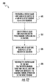
- FIG. 12 illustrates a method for mitigating loads in a pitch bearing of a wind turbine according to the present disclosure.
- the present subject matter is directed to a rotor blade assembly for a wind turbine having at least one shim plate configured between a rotor blade a hub to mitigate loads in a pitch bearing, such as ball contact stresses.
- the shim plate is generally a thin, optionally tapered or wedged piece of material, used to fill a gap or space between a rotor blade and a hub of the wind turbine.
- the shim plate(s) may also be integral with the rotor blade, the hub, and/or the pitch bearing.
- the pitch bearing generally includes an outer race, an inner race, and a plurality of roller elements between the outer race and the inner race such that the inner race is rotatable relative to the outer race.
- the at least one shim plate may be configured to fit between the inner race and a blade root of the rotor blade or between the outer race and a hub of the wind turbine so as to mitigate loads in the pitch bearing.
- the present subject matter as described herein provides many technical and commercial advantages.
- the addition of one or more shim plates configured between a new or existing rotor blade and a wind turbine hub can increase bearing load capacity without substantially increasing installation and/or maintenance costs.
- retrofitting existing wind turbines with one or more shim plates as disclosed herein does not require the use of costly cranes.
- FIG. 1 illustrates a side view of one embodiment of a wind turbine 10 according to the present disclosure.
- the wind turbine 10 generally includes a tower 12 , a nacelle 14 mounted on the tower 12 , and a rotor 16 coupled to the nacelle 14 .
- the rotor 16 includes a rotatable hub 18 and at least one rotor blade 20 coupled to and extending outwardly from the hub 18 .
- the rotor 16 includes three rotor blades 20 .
- the rotor 16 may include more or less than three rotor blades 20 .
- Each rotor blade 20 may be spaced about the hub 18 to facilitate rotating the rotor 16 to enable kinetic energy to be transferred from the wind into usable mechanical energy, and subsequently, electrical energy.
- the hub 18 may be rotatably coupled to an electric generator (not shown) positioned within the nacelle 14 to permit electrical energy to be produced.
- the rotor blade 20 includes a blade root 22 configured for mounting the rotor blade 20 to the hub 18 of the wind turbine 10 ( FIG. 1 ) and a blade tip 24 disposed opposite the blade root 22 .
- a body 26 of the rotor blade 20 may extend lengthwise between the blade root 22 and the blade tip 24 and may generally serve as the outer shell of the rotor blade 20 .
- the body 26 may define an aerodynamic profile (e.g., by defining an airfoil shaped cross-section, such as a symmetrical or cambered airfoil-shaped cross-section) to enable the rotor blade 20 to capture kinetic energy from the wind using known aerodynamic principles.
- the body 26 may generally include a pressure side 28 and a suction side 30 extending between a leading edge 32 and a trailing edge 34 .
- the rotor blade 20 may have a span 36 defining the total length of the body 26 between the blade root 22 and the blade tip 24 and a chord 38 defining the total length of the body 26 between the leading edge 32 and the trailing edge 34 .
- the chord 38 may vary in length with respect to the span 26 as the body 26 extends from the blade root 22 to the blade tip 24 .
- each root attachment assembly 40 may include a barrel nut 42 mounted within a portion of the blade root 22 and a root bolt 44 coupled to and extending from the barrel nut 42 so as to project outwardly from a root end 46 of the blade root 22 .
- the barrel nut 42 may be eliminated from the root attachment assembly 40 .
- each of the root attachment assemblies 40 may simply include a threaded root bolt 44 projecting outwardly from the root end 46 of the blade root 22 . By projecting outwardly from the root end 46 , the root bolts 44 may generally be used to couple the blade root 22 to the hub 18 (e.g., via a pitch bearing 50 ( FIG. 3 )), as will be described in greater detail below.
- FIGS. 3 and 4 several views of a rotor blade assembly 50 having shim plate 100 for mitigating loads in a pitch bearing 52 are illustrated in accordance with aspects of the present subject matter.
- FIG. 3 illustrates a cross-sectional view of the rotor blade assembly 50 having a plurality of shim plates 100 installed between the rotor blade 20 and the hub 18 .
- FIG. 4 illustrates an exploded view of the rotor blade assembly 50 according to the present disclosure.
- the rotor blade assembly 50 includes the rotor blade 20 coupled to the hub 18 via the pitch bearing 52 .
- the pitch bearing 52 includes an outer bearing race 54 , an inner bearing race 56 , and a plurality of roller elements (e.g., balls 58 ) disposed between the outer and inner races 54 , 56 .
- the outer race 54 is generally configured to be mounted to the hub 18 using a plurality of hub bolts 62 and/or other suitable fastening mechanisms.
- the inner race 56 is generally configured to be mounted to the blade root 22 of the rotor blade 20 using root bolts 44 .
- the root bolt(s) 44 extend between a first end 64 and a second end 66 .
- each root bolt 44 may be configured to be coupled to a portion of the inner race 56 , such as by coupling the first end 64 to the inner bearing race 56 using an attachment nut 68 and/or other suitable fastening mechanism.
- the second end 66 of each root bolt 44 may be configured to be coupled to the blade root 22 via a barrel nut 42 .
- the inner race 56 may be configured to be rotated relative to the outer race 54 (via the roller elements 58 ) to allow the pitch angle of each rotor blade 20 to be adjusted. As shown in FIG. 3 , such relative rotation of the outer and inner races 54 , 56 may be achieved using a pitch adjustment mechanism 72 mounted within a portion of the hub 18 .
- the pitch adjustment mechanism 72 may include any suitable components and may have any suitable configuration that allows the mechanism 72 to function as described herein.
- the pitch adjustment mechanism 72 may include a pitch drive motor 74 (e.g., an electric motor), a pitch drive gearbox 76 , and a pitch drive pinion 78 .
- the pitch drive motor 74 may be coupled to the pitch drive gearbox 76 so that the motor 74 imparts mechanical force to the gearbox 76 .
- the gearbox 76 may be coupled to the pitch drive pinion 78 for rotation therewith.
- the pinion 78 may, in turn, be in rotational engagement with the inner race 56 .
- a plurality of gear teeth 80 may be formed along an inner circumference 86 of the inner race 56 , with the gear teeth 80 being configured to mesh with corresponding gear teeth 82 formed on the pinion 78 .
- rotation of the pitch drive pinion 78 results in rotation of the inner race 56 relative to the outer race 54 and, thus, rotation of the rotor blade 20 relative to the hub 18 .
- FIG. 4 an exploded view of the rotor blade assembly 50 according to the present disclosure is illustrated.
- three shim plates 100 are spaced apart circumferentially about the inner race 56 of the pitch bearing 52 .
- the shim plates 100 may be configured between a top surface 88 of the inner race 56 and the blade root 22 . More specifically, at least one of the shim plates 100 is located approximate to a pressure side of the pitch bearing 52 corresponding to the pressure side surface 28 of the rotor blade 20 , whereas two shim plates 100 are located approximate to a suction side of the pitch bearing 52 corresponding to the suction side surface 30 of the rotor blade 20 .
- one or more shim plates 100 may be spaced circumferentially about the outer race 54 of the pitch bearing 52 and between the outer race 54 and the hub 18 .
- one shim plate 100 is located between the outer race 54 and the hub 18 .
- the shim plate 100 is configured between a bottom surface 92 of the outer race 54 and the hub 18 .
- the rotor blade assembly 50 may include any number of shim plates 100 and the shim plates 100 may be arranged at any location along the circumference of the pitch bearing 52 and between either the inner race and the blade root or the outer race and the hub. As such, the shim plates 100 can be located at any location on the pitch bearing 52 experiencing uneven loading, such as, for example, corresponding to a hard pressure spot.
- the top surface 88 of the inner race 56 defines a radial dimension R 1 ( FIG. 4 ), whereas and the shim plate 100 defines a width W ( FIG. 5 ) that is equal to or less than the radial dimension R 1 .
- the shim plate 100 fits within the radial dimension R 1 of the inner race 56 and does not extend within the open area within the inner race 56 . Additionally, in such an embodiment, the width W of the shim plate 100 does not interfere with the outer race 54 when the shim plate 100 is configured between the inner race 56 and the blade root 22 .
- the bottom surface 92 of the outer race 54 defines a radial dimension R 2 such that the width W of the shim plate 100 is equal to or less than the radial dimension R 2 .
- the shim plate 100 fits within the radial dimension R 2 of the outer race 54 and does not interfere with the inner race 56 when the shim plate 100 is configured between the outer race 54 and the hub 18 .
- FIGS. 5-11 various detailed embodiments of the shim plate according to the present disclosure are illustrated.
- FIGS. 5 and 6 illustrates close-up perspective views of various embodiments of the shim plate according to the present disclosure
- FIGS. 7-11 illustrate top and side views of further embodiments of the shim plate according to the present disclosure.
- the shim plate 100 , 150 , 200 has a base 102 , 152 , 202 and at least one tapered edge 104 , 154 , 204 .
- the base 102 may have a substantially rectangular cross-section as indicated by section A-A. As such, the base 102 has substantially linear radial edges 110 .
- the base 202 may have a substantially tapered cross-section as indicated by section B-B.
- the base 102 has at least one substantially tapered radial edge 210 .
- the shim plate 200 may include a tapered radial edge 210 across the full shim width W or across only a portion of the shim width W.
- the base 102 has a height H (or thickness) and a total length L 1 .
- the total length L 1 may be any suitable length and typically ranges from about 200 millimeters (mm) to about 3 meters (m).
- the height H may be any suitable height and/or thickness and typically ranges from about 0.5 mm to about 10 mm, such as, for example, 0.7 mm.
- the base 102 may have any suitable shape so as to fit in the desired locations as described herein.
- the base 102 has a typically arcuate shape so as to correspond with the shape of the inner 56 and outer 54 races of the pitch bearing 52 .
- the base 102 , 152 may have a rectangular, square, triangular, circular, or similar shape.
- the base 152 has a rectangular shape.
- the tapered edge(s) 104 , 154 , 204 are provided to allow intimate contact at all bearing perimeter locations with a finite in-plane shear stress in the blade shell. Further, the tapered edge(s) 104 , 154 , 204 minimize added friction that may exist due to rotation of the inner 56 and outer 54 bearing races. It should be understand that the term “tapered edges” is meant to encompass at least a tapered-sloped edge, as well as a tapered-stepped edge, as will be discussed in more detail herein. As shown in the embodiments of FIGS. 5 and 9 , the shim plate 100 may include opposing tapered edges 104 having corresponding slopes. For example, as depicted in the embodiment of FIG.
- the slope of each of the tapered edges 104 is equal to L 2 /H and L 3 /H, respectively.
- the lengths L 2 , L 3 of the tapered edges 104 may be any suitable length and typically ranges from about 250 mm to about 750 mm, such as, for example, 500 mm.
- the height H may be any suitable height and typically ranges from about 0.2 mm to about 10 mm, such as, for example, 0.7 mm.
- the corresponding slopes of the tapering edges ranges from about 0.00026 to about 0.04, such, for example, 0.0014.
- the slopes of the tapering edges 104 may be any appropriate slope to provide appropriate contact between the rotor blade 20 and the pitch bearing 52 and/or the hub 18 and the pitch bearing 52 .
- the shim plates 300 , 400 may include opposing tapered edges 304 , 404 having a step configuration. More specifically, as shown in FIG. 10 , the shim plate 300 may include multiple shim layers 308 having varying lengths and stacked atop one another until a suitable height H or thickness is obtained. It should be understood that the shim plates 100 , 200 , 300 , 400 described herein may include any number of shim layers 108 , 308 , 408 from one to greater than one. For example, as shown in FIG. 10 , the illustrated embodiment includes two shim layers 308 , whereas the shim plate 400 of FIG. 11 includes four shim layers 408 . In addition, each of the shim layers 308 , 408 has a varying length such that the varying lengths (e.g. L 4 and L 5 ) form the opposing tapered edges 304 , 404 having a step configuration.
- the varying lengths e.g. L 4 and L 5
- the opposing tapered edges 104 , 204 , 304 , 404 may be identical to one another or may vary according to any of the embodiments described herein.
- one of the edges may have a tapered-sloped configuration (as shown in FIG. 9 ), whereas the opposing edge may have a step configuration (as shown in FIGS. 10 and 11 ).
- both edges may have a tapered-sloped configuration; however, the slopes may vary.
- the shim plate 100 may include one or more through holes 106 for coupling the shim plate 100 between the inner race 56 and the blade root 22 or between the outer race 54 and the hub 18 .
- the through holes 106 of the shim plate 100 may correspond to the root bolts 44 of the blade root 22 or the hub bolts 62 of the hub 18 .
- the shim plate 150 may include one or more segments 158 , wherein each segment 158 has at least one slot 160 .
- the segments 158 may be inner and outer interlocking segments for inserting the shim plate 150 around corresponding bolts 44 , 62 .
- the slots 160 of the segments 158 may form the through holes 156 when the segments 158 are connected, i.e. inserted around a blade bolt or a hub bolt.
- the shim plate 100 may be secured between the inner race 56 and the blade root 22 or between the outer race 54 and the hub 18 using any other suitable means, such as adhesives or friction.
- the shim plate(s) described herein may be constructed of any suitable materials so as to mitigate loads experienced by the pitch bearing. In one embodiment, it is desirable for the joint of the material to be as stiff as possible. As such, in various embodiments, the shim plate(s) may be constructed of metal, such as steel or similar. In a further embodiment, the shim plate may be constructed of a composite material, such as a fiberglass laminate, similar to the rotor blade.
- the method 500 includes a step 502 of providing a rotor blade configured to couple to a hub of a wind turbine via the pitch bearing.
- the method 500 includes identifying at least one location on the pitch bearing experiencing a loading (step 504 ) and then installing at least one shim plate at the identified location (step 506 ).
- the method 500 then includes securing the rotor blade to the hub of the wind turbine via the pitch bearing such that the at least one shim plate mitigates the loading in the pitch bearing during operation of the wind turbine (step 508 ).
- the step 504 of identifying at least one location on the pitch bearing experiencing a loading further includes identifying a spar cap in the rotor blade.
- one or more shim plates can be placed in-line with the spar cap.
- one or more shim plates can be inserted on a pressure side surface of the rotor blade in-line with the spar cap, whereas one or more shim plates can be inserted on the suction side surface of the rotor blade adjacent to the spar cap.
- the step of installing at least one shim plate at the identified location further includes installing at least one shim plate between the rotor blade and the hub and spacing a plurality of shim plates circumferentially about the pitch bearing.
- the method 500 may include sizing the shim plate to accommodate the loading.
- the loading may be representative of bearing ball contact stresses, blade root resultant moments, hard pressure spots or similar.
- the step 506 of installing the at least one shim plate at the identified location may completed using a variety of techniques.
- the method may include positioning the rotor blade in a six o'clock position relative to the hub, loosening one or more blade bolts until a gap opens between the rotor blade and the hub, inserting the at least one shim plate over one of the blade bolts, and tightening the blade bolts such that the at least one shim plate is secured between the rotor blade and the hub so as to mitigate loads in the pitch bearing.
- one or more shim plates may be screwed into an end face of the pitch bearing, such as a top or bottom surface of the pitch bearing.
- the segments may be inserted around the blade bolts or hub bolts via corresponding slots and then secured between the rotor blade and the hub.
- one or more shim plates may be inserted over root bolts 44 before the rotor blade is coupled to the hub via the pitch bearing.
- one or more shim plates may be inserted over the hub bolts 62 .
- the method 500 may include removing one or more of the blade bolts, installing one or more of the shim plates in the location(s) of the corresponding removed blade bolts, and then replacing the blade bolts.
- the method 500 as described herein may also include machining the pitch bearing so as to provide one or more shim plates or protrusions integral with the pitch bearing, such as on the top or bottom surfaces of the pitch bearing.
- the method may include machining the hub or the rotor blade such that one or more shim plates or protrusions are provided in an end face of the hub or the rotor blade.
Landscapes
- Engineering & Computer Science (AREA)
- General Engineering & Computer Science (AREA)
- Mechanical Engineering (AREA)
- Life Sciences & Earth Sciences (AREA)
- Sustainable Development (AREA)
- Sustainable Energy (AREA)
- Chemical & Material Sciences (AREA)
- Combustion & Propulsion (AREA)
- Physics & Mathematics (AREA)
- Fluid Mechanics (AREA)
- Wind Motors (AREA)
Priority Applications (3)
| Application Number | Priority Date | Filing Date | Title |
|---|---|---|---|
| US14/036,463 US9523348B2 (en) | 2013-09-25 | 2013-09-25 | Rotor blade assembly with shim plate for mitigation pitch bearing loads |
| DK14185084.2T DK2853733T3 (da) | 2013-09-25 | 2014-09-17 | Rotorvingeanordning med underlagsplade til at dæmpe pitchlejebelastninger |
| EP14185084.2A EP2853733B1 (en) | 2013-09-25 | 2014-09-17 | Rotor blade assembly with shim plate for mitigating pitch bearing loads |
Applications Claiming Priority (1)
| Application Number | Priority Date | Filing Date | Title |
|---|---|---|---|
| US14/036,463 US9523348B2 (en) | 2013-09-25 | 2013-09-25 | Rotor blade assembly with shim plate for mitigation pitch bearing loads |
Publications (2)
| Publication Number | Publication Date |
|---|---|
| US20150086359A1 US20150086359A1 (en) | 2015-03-26 |
| US9523348B2 true US9523348B2 (en) | 2016-12-20 |
Family
ID=51542239
Family Applications (1)
| Application Number | Title | Priority Date | Filing Date |
|---|---|---|---|
| US14/036,463 Active 2035-04-10 US9523348B2 (en) | 2013-09-25 | 2013-09-25 | Rotor blade assembly with shim plate for mitigation pitch bearing loads |
Country Status (3)
| Country | Link |
|---|---|
| US (1) | US9523348B2 (da) |
| EP (1) | EP2853733B1 (da) |
| DK (1) | DK2853733T3 (da) |
Cited By (3)
| Publication number | Priority date | Publication date | Assignee | Title |
|---|---|---|---|---|
| US9915245B2 (en) * | 2014-04-17 | 2018-03-13 | Siemens Aktiengesellschaft | Reinforced pitch bearing of a wind turbine |
| US20180156203A1 (en) * | 2015-07-06 | 2018-06-07 | Vestas Wind Systems A/S | Segmented pitch ring for a wind turbine blade pitch system |
| US11619211B2 (en) | 2020-10-30 | 2023-04-04 | General Electric Renovables Espana, S.L. | Wind turbine pitch bearing with friction enhancing insert layer |
Families Citing this family (8)
| Publication number | Priority date | Publication date | Assignee | Title |
|---|---|---|---|---|
| DE102015216763B4 (de) * | 2015-09-02 | 2017-09-07 | Siemens Aktiengesellschaft | Entfernen eines vorderen oberen Gleitelements eines Gierlagers einer Windkraftanlage |
| FR3042238B1 (fr) * | 2015-10-09 | 2017-11-24 | Ntn-Snr Roulements | Roulement de pied de pale, systeme oscillant et systeme tournant |
| ES2874048T3 (es) * | 2016-10-24 | 2021-11-04 | Nordex Energy Spain S A | Turbina eólica y cojinete de paso de la turbina eólica |
| EP3318749B2 (en) * | 2016-11-04 | 2024-09-11 | Nordex Energy Spain, S.A.U. | Wind turbine |
| CN110232218B (zh) * | 2019-05-17 | 2023-06-16 | 许昌许继风电科技有限公司 | 一种风力发电机组叶片锁定装置强度的计算方法及装置 |
| EP3851668A1 (de) | 2020-01-17 | 2021-07-21 | Wobben Properties GmbH | Windenergieanlage, windenergieanlagen- rotorblatt und blattlagerung für eine windenergieanlage |
| EP3872334A1 (en) * | 2020-12-23 | 2021-09-01 | Vestas Wind Systems A/S | A method of prolonging pitch bearing lifetime and pitch bearing |
| CN115450861A (zh) * | 2022-09-30 | 2022-12-09 | 株洲时代新材料科技股份有限公司 | 一种用于风力发电叶片根部的缓冲装置 |
Citations (19)
| Publication number | Priority date | Publication date | Assignee | Title |
|---|---|---|---|---|
| US6783326B2 (en) | 2001-08-20 | 2004-08-31 | General Electric Company | Means for adjusting the rotor blade of a wind power plant rotor |
| US6942461B2 (en) | 2000-07-19 | 2005-09-13 | Aloys Wobben | Rotor blade hub |
| US20080104821A1 (en) | 2006-11-02 | 2008-05-08 | Ecotecnia, S.Coop.C.I | Device for fitting a seal |
| US20080191488A1 (en) | 2007-02-14 | 2008-08-14 | Nordex Energy Gmbh | Wind energy plant with a pitch bearing |
| US20080193295A1 (en) | 2007-02-14 | 2008-08-14 | Nordex Energy Gmbh | Wind energy plant with a rotor hub |
| US20080199315A1 (en) | 2005-07-08 | 2008-08-21 | Vestas Wind Systems A/S | Wind Turbine, a Hub for a Wind Turbine and Use Hereof |
| US20080213095A1 (en) | 2005-07-05 | 2008-09-04 | Vestas Wind Systems A/S | Wind Turbine Pitch Bearing, and Use Hereof |
| US20090022442A1 (en) | 2006-04-02 | 2009-01-22 | Anton Bech | Pitch Bearing For A Wind Turbine, A Wind Turbine And A Method For Servicing A Bearing |
| US20090087127A1 (en) | 2007-10-01 | 2009-04-02 | Siemens Aktiengesellschaft | Pitch bearing for wind turbine rotor blades |
| US20110138893A1 (en) | 2010-08-30 | 2011-06-16 | Mitsubishi Heavy Industries, Ltd. | Method for adjusting unevenness of top flange of wind turbine generator tower |
| US20110142645A1 (en) | 2009-12-16 | 2011-06-16 | Nunez Polo Miguel | Wind turbine blade bearing and wind turbine that makes use thereof |
| US20120183703A1 (en) | 2011-01-17 | 2012-07-19 | Janet Beaulieu | POM POM Device |
| US20120263598A1 (en) | 2011-04-14 | 2012-10-18 | Jens Thomsen | Pitch bearing |
| US8297929B2 (en) | 2006-11-13 | 2012-10-30 | Gamesa Innovation & Technology, S.L. | Reinforced bearing for a wind-power generator blade |
| US20120328443A1 (en) | 2011-05-31 | 2012-12-27 | Eugenio Yegro Segovia | Systems and methods for assembling a wind turbine with a pitch assembly |
| US8341840B2 (en) | 2010-02-10 | 2013-01-01 | Mitsubishi Heavy Industries, Ltd. | Method of repairing bearing of wind turbine generator |
| EP2546512A1 (en) | 2011-07-13 | 2013-01-16 | Alstom Wind, S.L.U. | Wind turbine rotor |
| JP2013137074A (ja) | 2011-12-28 | 2013-07-11 | Mitsubishi Heavy Ind Ltd | 風力発電装置用の軸受及び風力発電装置 |
| KR20130094075A (ko) | 2012-02-15 | 2013-08-23 | 삼성중공업 주식회사 | 풍력 발전기용 너트 풀림 감지 장치 |
-
2013
- 2013-09-25 US US14/036,463 patent/US9523348B2/en active Active
-
2014
- 2014-09-17 EP EP14185084.2A patent/EP2853733B1/en active Active
- 2014-09-17 DK DK14185084.2T patent/DK2853733T3/da active
Patent Citations (20)
| Publication number | Priority date | Publication date | Assignee | Title |
|---|---|---|---|---|
| US6942461B2 (en) | 2000-07-19 | 2005-09-13 | Aloys Wobben | Rotor blade hub |
| US6783326B2 (en) | 2001-08-20 | 2004-08-31 | General Electric Company | Means for adjusting the rotor blade of a wind power plant rotor |
| US8047792B2 (en) | 2005-07-05 | 2011-11-01 | Vestas Wind Systems A/S | Wind turbine pitch bearing, and use hereof |
| US20080213095A1 (en) | 2005-07-05 | 2008-09-04 | Vestas Wind Systems A/S | Wind Turbine Pitch Bearing, and Use Hereof |
| US20080199315A1 (en) | 2005-07-08 | 2008-08-21 | Vestas Wind Systems A/S | Wind Turbine, a Hub for a Wind Turbine and Use Hereof |
| US20090022442A1 (en) | 2006-04-02 | 2009-01-22 | Anton Bech | Pitch Bearing For A Wind Turbine, A Wind Turbine And A Method For Servicing A Bearing |
| US20080104821A1 (en) | 2006-11-02 | 2008-05-08 | Ecotecnia, S.Coop.C.I | Device for fitting a seal |
| US8297929B2 (en) | 2006-11-13 | 2012-10-30 | Gamesa Innovation & Technology, S.L. | Reinforced bearing for a wind-power generator blade |
| US20080191488A1 (en) | 2007-02-14 | 2008-08-14 | Nordex Energy Gmbh | Wind energy plant with a pitch bearing |
| US20080193295A1 (en) | 2007-02-14 | 2008-08-14 | Nordex Energy Gmbh | Wind energy plant with a rotor hub |
| US20090087127A1 (en) | 2007-10-01 | 2009-04-02 | Siemens Aktiengesellschaft | Pitch bearing for wind turbine rotor blades |
| US20110142645A1 (en) | 2009-12-16 | 2011-06-16 | Nunez Polo Miguel | Wind turbine blade bearing and wind turbine that makes use thereof |
| US8341840B2 (en) | 2010-02-10 | 2013-01-01 | Mitsubishi Heavy Industries, Ltd. | Method of repairing bearing of wind turbine generator |
| US20110138893A1 (en) | 2010-08-30 | 2011-06-16 | Mitsubishi Heavy Industries, Ltd. | Method for adjusting unevenness of top flange of wind turbine generator tower |
| US20120183703A1 (en) | 2011-01-17 | 2012-07-19 | Janet Beaulieu | POM POM Device |
| US20120263598A1 (en) | 2011-04-14 | 2012-10-18 | Jens Thomsen | Pitch bearing |
| US20120328443A1 (en) | 2011-05-31 | 2012-12-27 | Eugenio Yegro Segovia | Systems and methods for assembling a wind turbine with a pitch assembly |
| EP2546512A1 (en) | 2011-07-13 | 2013-01-16 | Alstom Wind, S.L.U. | Wind turbine rotor |
| JP2013137074A (ja) | 2011-12-28 | 2013-07-11 | Mitsubishi Heavy Ind Ltd | 風力発電装置用の軸受及び風力発電装置 |
| KR20130094075A (ko) | 2012-02-15 | 2013-08-23 | 삼성중공업 주식회사 | 풍력 발전기용 너트 풀림 감지 장치 |
Non-Patent Citations (1)
| Title |
|---|
| European Search Report and Written Opinion issued in connection with corresponding EP Application No. 14185084.2-1607 dated Feb. 4, 2015. |
Cited By (4)
| Publication number | Priority date | Publication date | Assignee | Title |
|---|---|---|---|---|
| US9915245B2 (en) * | 2014-04-17 | 2018-03-13 | Siemens Aktiengesellschaft | Reinforced pitch bearing of a wind turbine |
| US20180156203A1 (en) * | 2015-07-06 | 2018-06-07 | Vestas Wind Systems A/S | Segmented pitch ring for a wind turbine blade pitch system |
| US10823156B2 (en) * | 2015-07-06 | 2020-11-03 | Vestas Wind Systems A/S | Segmented pitch ring for a wind turbine blade pitch system |
| US11619211B2 (en) | 2020-10-30 | 2023-04-04 | General Electric Renovables Espana, S.L. | Wind turbine pitch bearing with friction enhancing insert layer |
Also Published As
| Publication number | Publication date |
|---|---|
| EP2853733A1 (en) | 2015-04-01 |
| DK2853733T3 (da) | 2018-02-05 |
| EP2853733B1 (en) | 2018-01-03 |
| US20150086359A1 (en) | 2015-03-26 |
Similar Documents
| Publication | Publication Date | Title |
|---|---|---|
| EP2853733B1 (en) | Rotor blade assembly with shim plate for mitigating pitch bearing loads | |
| US9951815B2 (en) | Pitch bearing assembly with stiffener | |
| US9551324B2 (en) | Pitch bearing assembly with stiffener | |
| US9188107B2 (en) | Wind turbine bearings | |
| US9777704B2 (en) | Rotor blade assembly for a wind turbine having variable-length blade bolts | |
| US9239040B2 (en) | Root end assembly configuration for a wind turbine rotor blade and associated forming methods | |
| US9464622B2 (en) | Rotor blade assembly having a stiffening root insert | |
| US7993103B2 (en) | Wind turbine blades and methods of attaching such blades to a hub | |
| EP2868916A1 (en) | Chord extenders for a wind turbine rotor blade assembly | |
| EP3736438B1 (en) | Rotor assembly having a pitch bearing with a stiffener ring | |
| US20150093250A1 (en) | Root stiffener assembly for a wind turbine rotor blade | |
| US20140377078A1 (en) | Root stiffener for a wind turbine rotor blade | |
| US20140119926A1 (en) | Wind turbine rotor blade assembly with a ring insert in the blade root | |
| US20150233260A1 (en) | Wind turbine blade with fastening means | |
| US20140064971A1 (en) | Stiffener plate for a wind turbine | |
| EP3112669B1 (en) | Pitch assembly for a wind turbine rotor blade | |
| US9261074B2 (en) | Variable bolt parameters for a wind turbine rotor blade | |
| US20150056078A1 (en) | Pitch bearing assembly with stiffener | |
| US20180283362A1 (en) | Pitch Bearing for a Wind Turbine | |
| US20120027618A1 (en) | Angled blade root | |
| EP3470671A1 (en) | Wind turbine pitch bearing with line contact rolling elements | |
| CA3097996A1 (en) | Pitch bearing for a wind turbine | |
| US20170321662A1 (en) | Wind turbine bearings | |
| EP3249219B1 (en) | Wind turbine bearings | |
| CN219139256U (zh) | 一种叶根连接结构及风力发电机组 |
Legal Events
| Date | Code | Title | Description |
|---|---|---|---|
| AS | Assignment |
Owner name: GENERAL ELECTRIC COMPANY, NEW YORK Free format text: ASSIGNMENT OF ASSIGNORS INTEREST;ASSIGNORS:JACOBSEN, ERIC MORGAN;MINADEO, ADAM DANIEL;VOSSLER, ALEXANDER WILLIAM;REEL/FRAME:031277/0663 Effective date: 20130924 |
|
| STCF | Information on status: patent grant |
Free format text: PATENTED CASE |
|
| MAFP | Maintenance fee payment |
Free format text: PAYMENT OF MAINTENANCE FEE, 4TH YEAR, LARGE ENTITY (ORIGINAL EVENT CODE: M1551); ENTITY STATUS OF PATENT OWNER: LARGE ENTITY Year of fee payment: 4 |
|
| AS | Assignment |
Owner name: GE INFRASTRUCTURE TECHNOLOGY LLC, SOUTH CAROLINA Free format text: ASSIGNMENT OF ASSIGNORS INTEREST;ASSIGNOR:GENERAL ELECTRIC COMPANY;REEL/FRAME:065727/0001 Effective date: 20231110 |
|
| MAFP | Maintenance fee payment |
Free format text: PAYMENT OF MAINTENANCE FEE, 8TH YEAR, LARGE ENTITY (ORIGINAL EVENT CODE: M1552); ENTITY STATUS OF PATENT OWNER: LARGE ENTITY Year of fee payment: 8 |