US9598092B2 - Railcar energy absorption/coupling system - Google Patents
Railcar energy absorption/coupling system Download PDFInfo
- Publication number
- US9598092B2 US9598092B2 US14/540,209 US201414540209A US9598092B2 US 9598092 B2 US9598092 B2 US 9598092B2 US 201414540209 A US201414540209 A US 201414540209A US 9598092 B2 US9598092 B2 US 9598092B2
- Authority
- US
- United States
- Prior art keywords
- yoke
- energy absorption
- coupling system
- draft
- coupler
- Prior art date
- Legal status (The legal status is an assumption and is not a legal conclusion. Google has not performed a legal analysis and makes no representation as to the accuracy of the status listed.)
- Active, expires
Links
- 238000010521 absorption reaction Methods 0.000 title claims abstract description 169
- 230000008878 coupling Effects 0.000 title claims abstract description 169
- 238000010168 coupling process Methods 0.000 title claims abstract description 169
- 238000005859 coupling reaction Methods 0.000 title claims abstract description 169
- 230000007935 neutral effect Effects 0.000 claims abstract description 55
- 238000000926 separation method Methods 0.000 claims description 12
- 230000001105 regulatory effect Effects 0.000 claims description 4
- 230000000712 assembly Effects 0.000 description 20
- 238000000429 assembly Methods 0.000 description 20
- 229910000831 Steel Inorganic materials 0.000 description 4
- 238000005266 casting Methods 0.000 description 4
- 238000009434 installation Methods 0.000 description 4
- 239000010959 steel Substances 0.000 description 4
- 230000003137 locomotive effect Effects 0.000 description 3
- 230000009471 action Effects 0.000 description 2
- 230000008859 change Effects 0.000 description 2
- 230000006835 compression Effects 0.000 description 2
- 238000007906 compression Methods 0.000 description 2
- 238000012986 modification Methods 0.000 description 2
- 230000004048 modification Effects 0.000 description 2
- 239000010421 standard material Substances 0.000 description 2
- 239000000872 buffer Substances 0.000 description 1
- 238000000034 method Methods 0.000 description 1
- 230000008569 process Effects 0.000 description 1
- 230000035939 shock Effects 0.000 description 1
Images




Classifications
-
- B—PERFORMING OPERATIONS; TRANSPORTING
- B61—RAILWAYS
- B61G—COUPLINGS; DRAUGHT AND BUFFING APPLIANCES
- B61G7/00—Details or accessories
- B61G7/10—Mounting of the couplings on the vehicle
-
- B—PERFORMING OPERATIONS; TRANSPORTING
- B61—RAILWAYS
- B61G—COUPLINGS; DRAUGHT AND BUFFING APPLIANCES
- B61G11/00—Buffers
-
- B—PERFORMING OPERATIONS; TRANSPORTING
- B61—RAILWAYS
- B61G—COUPLINGS; DRAUGHT AND BUFFING APPLIANCES
- B61G9/00—Draw-gear
- B61G9/04—Draw-gear combined with buffing appliances
-
- B—PERFORMING OPERATIONS; TRANSPORTING
- B61—RAILWAYS
- B61G—COUPLINGS; DRAUGHT AND BUFFING APPLIANCES
- B61G9/00—Draw-gear
- B61G9/04—Draw-gear combined with buffing appliances
- B61G9/06—Draw-gear combined with buffing appliances with rubber springs
Definitions
- the present invention disclosure generally relates to railroad cars and, more specifically, to a railcar energy absorption/coupling system for absorbing both buff and draft forces normally encountered by railcars during make-up and operation of a train consist.
- Such a system typically includes a draft assembly comprised of a coupler for releasably attaching two railcars to each other and a cushioning assembly arranged in operable combination with each coupler for absorbing and returning energy imparted thereto during make-up of the train consist and during in-service operation of the railcar.
- In-service train action events and impacts occurring during the “make-up” of a train consist subject the draft assembly at opposed ends of the railcars to buff impacts, and in-service train action events subject the draft assembly to draft impacts.
- the impacts associated with these events are transmitted from the couplers to the respective cushioning assembly and, ultimately, to the railcar body. That is, as the couplers are pushed or pulled, be it during in-service operations and/or during the “make-up” of a train consist, such movements, although muted to some degree by the cushioning assembly, are translated to the railcar body.
- draft assemblies further include a yoke that is operably coupled to the coupler as through a pin or key, a follower, and the cushioning assembly.
- the follower is positioned against or arranged closely adjacent to the butt or rear end of a shank portion on the coupler in the draft pocket and within confines defined by the yoke.
- the cushioning assembly is positioned between the follower and rear stops on the draft sill.
- the next to the last railcar may be moving at 4 miles per hour.
- the slack in the energy absorption/coupling system of those railcars closest to the locomotive is taken up very rapidly and those two railcars closest to the locomotive are subjected to a very large impact event being placed thereon. Such large impact events are capable of damaging the lading in the railcars.
- a railcar energy absorption/coupling system including an axially elongated draft sill defining a draft pocket between front stops and rear stops on the draft sill.
- the railcar energy absorption/coupling system also includes a coupler having a head portion and shank portion. As is typical, the head portion of the coupler axially extends beyond one end of the draft sill.
- a cushioning assembly is provided in operable combination with the coupler for absorbing and returning energy. The cushioning assembly is positioned in the draft pocket between the front and rear stops.
- a yoke also forms part of the energy absorption/coupling system of this invention disclosure.
- the yoke consists of a back wall, a top wall joined to and axially extending from the back wall toward an open forward end, and a bottom wall joined to and axially extending from the back wall toward the open forward end of the yoke.
- the back wall of the yoke is disposed to contact the rear end of the cushioning assembly.
- the top and bottom walls of the yoke are operably coupled to the shank portion of the coupler toward the forward end of the yoke.
- a coupler follower is positioned between a free end of the shank portion of the coupler and a forward end of the cushioning assembly.
- each of the top and bottom walls of the yoke with two forward facing stop members which extend in opposed lateral directions from each other.
- the two forward facing stop members on the top wall of the yoke are arranged in generally coplanar relation with the two forward facing stop members on the bottom wall of the yoke.
- the energy absorption/coupling system has a neutral position, a full buff position disposed a first predetermined distance from the neutral position, and a full draft position disposed a second predetermined distance from the neutral position, with the full buff and full draft positions for the energy absorption coupling system being disposed in opposite directions from the neutral position.
- the draft pocket defined by the draft sill has a length of about 24.625 inches between confronting surfaces on the front and rear stops.
- the coupler follower includes a forward facing surface which is biased into contacting relation with the front stops on the draft sill by the draft gear when the yoke is in the neutral position.
- the first predetermined distance traveled by the system is generally equal to the second predetermined distance traveled by the system.
- each railcar energy absorption/coupling system will have a total combined travel in both buff and draft directions of about 6.5 inches.
- the stops on the yoke guard against adjacent railcars from becoming inadvertently separated from each other.
- the stop members are formed integral with the top and bottom walls of the yoke.
- the cushioning assembly forming part of the energy absorbing/coupling system includes a railcar draft gear assembly including a walled housing.
- the housing of the draft gear has a closed end and an open end.
- a railcar energy absorption/coupling system including an axially elongated draft sill defining a draft pocket between front stops and rear stops on the draft sill.
- the railcar energy absorption/coupling system also includes a coupler having a head portion and shank portion, with the head portion of the coupler axially extending beyond the draft sill.
- the railcar energy absorption/coupling system includes a first cushioning assembly arranged in the draft pocket on the draft sill for absorbing and returning energy imparted thereto.
- This alternative embodiment of the energy absorption/coupling system also includes a second cushioning assembly arranged in the draft pocket on the draft sill in axially aligned relation with the first cushioning assembly for absorbing and returning energy imparted thereto.
- a yoke also forms part of the energy absorption/coupling system of this invention disclosure.
- the yoke consists of a back wall, a top wall joined to and axially extending from the back wall toward an open forward end, and a bottom wall joined to and axially extending from the back wall toward the open forward end, with the back wall of the yoke being disposed to contact a rear end of the second cushioning assembly, and with the top and bottom walls of the yoke being operably coupled to the shank portion of the coupler toward a forward end of the yoke.
- a coupler or first follower is positioned between a free end of the shank portion of the coupler and a forward end of the first cushioning assembly.
- a second or rear follower is disposed between a rear end of the first cushioning assembly and a forward end of the second cushioning assembly.
- each of the top and bottom walls of the yoke define two forward facing stop members which extend in opposed lateral directions from each other.
- the two forward facing stop members on the top wall of the yoke are arranged in generally coplanar relation with the two forward facing stop members on the bottom wall of the yoke.
- the second embodiment of the energy absorption/coupling system has a neutral position, a full buff position disposed a first predetermined distance from the neutral position, and a full draft position disposed a second predetermined distance from the neutral position, with the full buff and full draft positions for the energy absorption coupling system being disposed in opposite directions from the neutral position.
- the draft pocket defined by the draft sill in this second embodiment of the invention disclosure has a length of about 49.25 inches between confronting surfaces on the front and rear stops.
- the coupler follower includes a forward facing surface which is biased into contacting relation with the front stops on the draft sill by the first and second draft gears when the yoke is in the neutral position. So as to enhance the absorption capacity of the system, the yoke will have a total combined travel in both buff and draft directions of about 10.0 inches.
- the stop members on the yoke are preferably designed to allow more buff travel than draft travel by limiting the draft travel and additionally preventing potential separation of the coupler from the draft sill.
- the stop members are formed integral with the top and bottom walls of the yoke.
- the first cushioning assembly includes a draft gear assembly having a walled housing.
- the second cushioning assembly includes a draft gear assembly having a walled housing.
- the walled housing of each draft gear assembly preferably has a closed end and an open end.
- draft gears, buffers and/or other forms of cushioning unit systems are used in pocket locations described by draft gear assemblies in the present invention disclosure.
- a railcar energy absorption/coupling system including an axially elongated draft sill defining a draft pocket between front stops and rear stops on the draft sill.
- the railcar energy absorption/coupling system also includes a coupler having a head portion and shank portion. As is typical, the head portion of the coupler axially extends beyond one end of the draft sill.
- a cushioning assembly is provided in operable combination with the coupler for absorbing and returning energy. The cushioning assembly is positioned in the draft pocket between the front and rear stops.
- the cushioning assembly includes a walled housing.
- a yoke also forms part of the energy absorption/coupling system of this invention disclosure.
- the yoke consists of a back wall, a top wall joined to and axially extending from the back wall toward an open forward end, and a bottom wall joined to and axially extending from the back wall toward the open forward end of the yoke.
- the back wall of the yoke is disposed to contact the rear end of the cushioning assembly.
- the top and bottom walls of the yoke are operably coupled to the shank portion of the coupler toward the forward end of the yoke.
- the top and bottom walls of the yoke embrace the housing of the cushioning assembly therebetween.
- a coupler follower is positioned between a free end of the shank portion of the coupler and a forward end of the cushioning assembly.
- the top and bottom walls of the yoke each have two forward facing stop members which extend in opposed lateral directions from each other.
- the two forward facing stop members on the top wall of the yoke are arranged in generally coplanar relation with the two forward facing stop members on the bottom wall of the yoke.
- the energy absorption/coupling system has a neutral position, a full buff position disposed a first predetermined distance from the neutral position, and a full draft position disposed a second predetermined distance from the neutral position, with the full buff and full draft positions for the energy absorption coupling system being disposed in opposite directions from the neutral position.
- the rear end of the cushioning assembly When the energy absorption/coupling system of this invention disclosure is in a full buff position, the rear end of the cushioning assembly is positioned against the rear stops on the draft sill. Whereas, when the energy absorption/coupling system of this invention disclosure is in a full draft position, the stop members on the yoke operably engage with the forward stops on the draft sill. With this invention disclosure, the draft travel of the energy absorption/coupling system is independently controlled relative to buff travel of the energy absorption/coupling system and is regulated as a function of the location of the four stop members on the yoke.
- the draft pocket defined by the draft sill has a length of about 24.625 inches between confronting surfaces on the front and rear stops.
- the coupler follower includes a forward facing surface which is biased into contacting relation with the front stops on the draft sill by the draft gear when the yoke is in the neutral position.
- the first predetermined distance traveled by the system is generally equal to the second predetermined distance traveled by the system.
- each railcar energy absorption/coupling system will have a total combined travel in both buff and draft directions of about 6.5 inches.
- the stops on the yoke guard against adjacent railcars from becoming inadvertently separated from each other.
- the stop members on the yoke are formed integral with the top and bottom walls of the yoke.
- a railcar energy absorption/coupling system including an axially elongated draft sill defining a draft pocket between front stops and rear stops on the draft sill.
- the railcar energy absorption/coupling system also includes a coupler having a head portion and shank portion. As is typical, the head portion of the coupler axially extends beyond one end of the draft sill.
- a cushioning assembly is provided in operable combination with the coupler for absorbing and returning energy. The cushioning assembly is positioned in the draft pocket between the front and rear stops
- a yoke also forms part of the energy absorption/coupling system of this invention disclosure.
- the yoke consists of a back wall, a top wall joined to and axially extending from the back wall toward an open forward end, and a bottom wall joined to and axially extending from the back wall toward the open forward end of the yoke.
- the back wall of the yoke serves to operably interconnect the top and bottom walls of the yoke.
- the top and bottom walls of the yoke are operably coupled to the shank portion of the coupler toward the forward end of the yoke.
- a coupler follower is positioned between a free end of the shank portion of the coupler and a forward end of the cushioning assembly.
- the top and bottom walls of the yoke each have two forward facing stop members which extend in opposed lateral directions from each other.
- the two forward facing stop members on the top wall of the yoke are arranged in generally coplanar relation with the two forward facing stop members on the bottom wall of the yoke.
- the energy absorption/coupling system has a neutral position, a full buff position disposed a first predetermined distance from the neutral position, and a full draft position disposed a second predetermined distance from the neutral position, with the full buff and full draft positions for the energy absorption coupling system being disposed in opposite directions from the neutral position.
- the stop members on the yoke are operably engaged with the forward stops on said sill when the energy absorption/coupling system is in the full draft position,
- the draft travel of the energy absorption/coupling system is independently controlled relative to buff travel of the energy absorption/coupling system and is regulated as a function of the location of the four stop members on the yoke.
- the coupler follower includes a forward facing surface which is biased into contacting relation with the front stops on the draft sill when the yoke is in the neutral position.
- the first predetermined distance traveled by the system is generally equal to the second predetermined distance traveled by the system.
- the stops on the yoke guard against adjacent railcars from becoming inadvertently separated from each other.
- the stop members on the yoke are formed integral with the top and bottom walls of the yoke.
- the stops on the yoke are arranged in generally coplanar relationship relative to the top and bottom walls on the yoke.
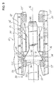
- FIG. 1 is a side view of a railcar embodying principals and teachings of the present invention disclosure
- FIG. 2 is an enlarged fragmentary longitudinal sectional view of a portion of one embodiment of an energy absorption/coupling system embodying principals and teachings of this invention disclosure
- FIG. 3 is a sectional view taken along line 3 - 3 of FIG. 2 ;
- FIG. 4 is a sectional view taken along line 4 - 4 of FIG. 3 showing the first embodiment of the energy absorption/coupling system in a neutral position;
- FIG. 5 is a perspective view of one element of the energy absorption/coupling system shown in FIGS. 2 and 3 ;
- FIG. 6 is an enlarged view similar to FIG. 2 showing the energy absorption/coupling system in a full buff position
- FIG. 7 is an enlarged view similar to FIG. 4 showing the energy absorption/coupling system in a full buff position
- FIG. 8 is an enlarged view similar to FIG. 6 showing the energy absorption/coupling system in a full draft position
- FIG. 9 is an enlarged view similar to FIG. 7 showing the energy absorption/coupling system in a full draft position
- FIG. 10 is an enlarged fragmentary longitudinal sectional view of a portion of a second embodiment of an energy absorption/coupling system embodying principals and teachings of this invention disclosure
- FIG. 11 is a sectional view taken along line 11 - 11 of FIG. 10 ;
- FIG. 12 is a sectional view taken along line 12 - 12 of FIG. 11 showing the second embodiment of the energy absorption/coupling system in a neutral position
- FIGS. 13 and 14 are perspective views of two elements of the energy absorption/coupling system shown in FIGS. 10 and 12 ;
- FIG. 15 is an enlarged view similar to FIG. 7 showing the second embodiment of the energy absorption/coupling system in a full buff position;
- FIG. 16 is an enlarged view similar to FIG. 6 showing the second embodiment of the energy absorption/coupling system in a full buff position
- FIG. 17 is an is an enlarged view similar to FIG. 9 showing the second embodiment of the energy absorption/coupling system in a full or limited draft position.
- FIG. 18 is an enlarged view similar to FIG. 8 showing the second embodiment of the energy absorption/coupling system in a full or limited draft position.
- FIG. 1 a railroad car, generally indicated by reference numeral 10 .
- railcar 10 has a railcar body 12 , in whatever form, supported on a draft sill or centersill 14 ( FIG. 2 ) defining a longitudinal axis 16 ( FIG. 2 ) for and extending substantially the length of railcar 10 .
- Railcar 10 includes a conventional brake system which is preferably operated by air.
- air hoses 17 extend from opposite ends of the car and operably connect with air hoses from an axially adjacent railcar after the cars are coupled in a train consist relative to each other.
- an energy absorption/coupling system generally identified by reference numeral 20 , and embodying teachings and principals of this invention disclosure is provided toward opposed ends of the railcar 10 .
- the energy absorption/coupling system provided toward opposed ends of the railcar 10 are substantially identical and, thus, are both identified by reference numeral 20 .
- the draft sill or centersill 14 shown by way of example in FIG. 2 can be cast or fabricated and has standard features.
- the centersill 14 has stops including laterally spaced front stops 23 and laterally spaced rear stops 23 ′ connected to laterally spaced walls 24 and 26 of the centersill 14 ( FIG. 3 ).
- the front and rear stops 23 and 23 ′, respectively, are longitudinally spaced apart from each other.
- the centersill 14 also has a top wall 28 , although it will be appreciated the present invention disclosure is equally applicable to and can be used with a draft sill lacking such a top wall.
- the stops 23 , 23 ′ on the centersill 14 combine to define a draft gear pocket 30 therebetween.
- the centersill 14 can have other standard features and is preferably made of standard materials in standard ways.
- the energy absorption/coupling system 20 of this invention disclosure may advantageously be used with either cast or fabricated draft sills.
- the draft gear pocket i.e., the longitudinal distance between the inboard faces of the front stops 23 and the inboard faces of the rear stops 23 ′, measures 24.625 inches.
- each energy absorption/coupling system 20 has a draft assembly 40 primarily including a standard coupler 50 and a cushioning assembly 80 disposed in longitudinally disposed and operable combination relative to each other.
- the standard coupler 50 of each draft assembly 40 includes a head portion 52 and shank portion 54 , preferably formed as a one-piece casting.
- the coupler head portion 52 extends longitudinally outward from the centersill 14 to engage a similar coupler 50 ′ extending from an end of a second and adjacent railcar to be releasably coupled or otherwise connected to car 10 .
- the shank portion 54 is guided for generally longitudinal movements by the centersill 14 of the railcar 10 .
- each draft assembly 40 furthermore includes a yoke 60 which, in one form, comprises a steel casting or it can be fabricated from separate steel components.
- yoke 60 is configured for use with a standard F coupler but it will be appreciated with slight redesign efforts known to those skilled in the art, the teachings and principals of this invention disclosure equally apply to a yoke which is configured for use with a standard E coupler without detracting or departing from the novel spirit and broad scope of this invention disclosure.
- yoke 60 has a sideways inverted generally U-shaped configuration including back wall 62 , an axially elongated top wall 64 joined to and axially extending from the back wall 62 toward the forward end of the cushioning assembly 80 and an elongated bottom wall 66 joined to and axially extending from the back wall 62 toward the forward end of the cushioning assembly 80 .
- the top wall 64 and bottom wall 66 of yoke 60 extend generally parallel and are separated from each other to define a linearly unobstructed chamber 67 ( FIG. 2 ) which readily accommodates the cushioning assembly 80 therein ( FIG. 3 ).
- the top and bottom walls 64 and 66 , respectively, of yoke 60 embrace the cushioning assembly 80 therebetween and allow for endwise sliding movements of the cushioning assembly relative thereto.
- the yoke 60 is configured such that the back wall 62 of the yoke 60 presses against and pushes the cushioning assembly 80 forward during a draft operation of the energy absorption/coupling system 20 .
- yoke 60 is operably coupled to the shank portion 54 of coupler 50 as by a key or pin.
- the cushioning assembly 80 of each energy absorption/coupling system 20 is installed in general alignment with the longitudinal axis 16 between the stops 23 , 23 ′ for absorbing and dissipating both buff and draft dynamic impact forces (loads), axially applied to the draft assembly 40 during make-up of a train consist and in-service operations of such a train consist.
- the cushioning assembly 80 can take on any of a myriad of different designs and different operating characteristics without seriously departing or detracting from the true spirit and novel concept of this invention disclosure.
- the cushioning assembly 80 illustrated in the drawings can include a draft gear assembly designated by reference numeral 81 which can be accommodated in a conventionally sized draft gear pocket.
- the draft gear assembly 81 can be of the type manufactured and sold by Miner Enterprises, Inc. of Geneva, Ill. under Model No. TF-880 or Model No. Crown SE or any other equivalent and conventional draft gear assembly.
- the essential elements of the draft gear assembly 81 include: a hollow metallic housing 82 having a closed rear end 84 and an open forward end 86 and series of walls 88 extending between the ends 84 and 86 , a spring biased linearly reciprocal wedge member 90 forming part of a friction clutch assembly 92 , and a spring assembly 94 which, in the illustrated embodiment, is operably positioned within the draft gear assembly housing 82 .
- the top and bottom walls 64 and 66 , respectively, of the yoke 60 embrace the housing 82 of draft gear assembly 81 therebetween.
- FIG. 3 the top and bottom walls 64 and 66 , respectively, of the yoke 60 embrace the housing 82 of draft gear assembly 81 therebetween.
- a free end 91 of the wedge member 90 typically extends a predetermined distance D 1 past the open end 86 of the housing 82 when the yoke 60 is in a neutral position.
- the free end 91 of the wedge member 90 axially extends about 3.25 inches beyond the open end of the draft gear housing 82 when the yoke 60 is in a neutral position.
- the draft gear assembly 81 is designed to both consistently and repeatedly withstand impact events directly axially theretoward.
- each draft assembly 40 furthermore includes a coupler follower 68 disposed between an inner or free end 56 of the shank portion 54 of coupler 50 and the cushioning assembly 80 .
- the follower 68 is movable between the top wall 64 and bottom wall 66 of the associated yoke 60 in a forward and rearward longitudinal direction.
- the coupler follower 68 has a forward facing generally flat first surface 69 which engages with the free end 56 of the shank portion 54 of coupler 50 and a second rear facing generally flat second surface 69 ′ which engages with the forward end of the cushioning assembly 80 .
- the coupler follower 68 is arranged in operable combination with and presses against the free end of the wedge member 90 of the draft gear assembly 81 when the energy absorption/coupling system 20 is installed in the centersill or draft sill 14 .
- the faces 69 and 69 ′ of the coupler follower 68 are generally parallel relative to each other.
- the forward facing first surface 69 of the coupler follower 68 can have a contoured/concave recess (not shown) for accommodating the free end 56 of the shank portion 54 of coupler 50 without detracting or departing from the true spirit and broad scope of this invention disclosure.
- the cushioning assembly 80 of each system 20 can be relatively easily installed in the pocket 30 using standard and well known installation procedures and in operable combination with the coupler 50 .
- standard support members 95 FIGS. 2 and 3
- flanges 25 and 27 on the centersill walls 24 and 26 respectively, to operably support the yoke 60 and draft gear assembly 81 within pocket 30 and in operable association with the coupler 50 .
- the top wall 64 of the yoke 60 has a pair of laterally spaced and laterally aligned stop members 74 and 74 ′ which extend in opposed lateral directions from each other.
- the bottom wall 66 of the yoke 60 also has a pair of laterally spaced and laterally aligned stop members 76 and 76 ′ ( FIG. 3 ) which extend in opposed lateral directions from each other.
- the stop members 74 , 74 ′ are formed integral with the top wall 64 of yoke 60 while the stop members 76 , 76 ′ are formed integral with the bottom wall 66 of yoke 60 .
- the stop members 74 , 74 ′, 76 and 76 ′ are arranged relative to each other to provide the yoke 60 with four co-planar forward-facing stopping surfaces 77 , 77 ′ and 78 , 78 ′. As shown in the embodiment illustrated by way of example in FIG. 3 , two stopping surfaces 77 , 77 ′ on the yoke 60 are disposed above the longitudinal axis 16 and in generally coplanar relationship with the top wall 64 of yoke 60 while two stopping surfaces on the yoke 60 are disposed below the longitudinal axis 16 and in generally coplanar relationship with the bottom wall 66 of the yoke 60 .
- two stopping surfaces 77 and 78 on the yoke 60 are preferably disposed to one lateral side of the longitudinal axis 16 while two additional stopping surfaces 77 ′ and 78 ′ are disposed to an opposed lateral side of the axis 16 .
- the co-planar forward-facing stop surfaces 77 , 77 ′ and 78 , 78 ′ on the yoke 60 are disposed at a predetermined distance D 2 from the confronting surface on the front stops 23 on the draft sill 14 when yoke 60 is in a neutral position.
- the co-planar forward-facing stop surfaces 77 , 77 ′ and 78 , 78 ′ on the yoke 60 will operably contact the front stops 23 on the draft sill 14 thereby limiting draft travel while also limiting compression of the cushioning assembly 80 .
- the co-planar forward-facing stop surfaces 77 , 77 ′ and 78 , 78 ′ on the yoke 60 will contact the front stops 23 on the draft sill 14 .
- the stop members 74 , 74 ′, 76 and 76 ′ prevent potential separation of the coupler 50 from the draft gear sill 14 should a catastrophe occur regarding yoke 60 .
- the predetermined distance D 2 the co-planar forward-facing stop surfaces 77 , 77 ′ and 78 , 78 ′ on the yoke 60 is disposed from the confronting surface on the front stops 23 on the draft sill 14 is about equal to or less than the predetermined distance D 1 the free end of wedge member 90 axially extends beyond the open end 86 of the draft gear housing 82 when the energy absorption/coupling system 20 is in a neutral position.
- FIGS. 2 and 4 show the energy absorption/coupling system 20 in a substantially neutral position.
- FIGS. 6 and 7 show the energy absorption/coupling system 20 in a full buff position.
- the rear stops 23 ′ on the centersill 14 allow the energy absorption/coupling system 20 to be disposed about 3.25 inches from the neutral position when in a full buff position with the rear end 84 of the draft gear housing 82 being positioned against the stops 23 ′ on the draft gear sill 14 .
- the four co-planar forward-facing stopping surfaces 77 , 77 ′ and 78 , 78 ′ on the stop members 74 , 74 ′ and 76 . 76 ′, respectively, preferably extend at least the predetermined distance D 2 from the front stop members 23 on the centersill 14 .
- FIGS. 8 and 9 show the energy absorption/coupling system 20 in a full draft position.
- the yoke 60 is drawn to the left under the influence of the coupler 50 .
- the cushioning assembly 80 axially compresses.
- the spring assembly 94 ( FIG. 8 ) of the draft gear assembly 81 is compressed by the wedge member 90 axially retracting within the housing as the free end 91 of the wedge member 90 presses against the coupler follower 68 which is halted from further movement to the left by the front stops 23 .
- the multiple co-planar forward-facing stopping surfaces 77 , 77 ′ and 78 , 78 ′ defined by the stop members 74 , 74 ′ and 76 , 76 ′, respectively, allow the yoke 60 to travel the distance D 2 ( FIGS. 6 and 7 ) from the neutral position to a full draft position.
- the stop members 74 , 74 ′ and 76 , 76 ′ : 1) limit draft travel; 2) maximize buff travel; and, 3) limit total combined travel of the energy absorption coupling system 20 while furthermore preventing inadvertent separation of the railcars and unwarranted braking and/or separation of the air hoses 17 ( FIG. 1 ).
- the energy absorption/coupling system 20 will have a combined travel in both buff and draft directions of about 6.5 inches. It should be readily appreciated from the above disclosure, however, the travel of the yoke 60 during the draft operation of the energy absorption/coupling system 20 can be modified to change the combined travel in both buff and draft directions to less than 6.5 inches simply by relocating the multiple co-planar forward-facing stopping surfaces 77 , 77 ′ and 78 , 78 ′ defined by the stop members 74 , 74 ′ and 76 , 76 ′ from that disclosed without detracting or departing from the true sprit and novel concept of this invention disclosure.
- FIGS. 10 through 18 An alternative embodiment of an energy absorption/coupling system is illustrated in FIGS. 10 through 18 .
- This alternative embodiment of an energy absorption/coupling system is designated generally by reference numeral 120 .
- Those elements of this alternative embodiment of an energy absorption/coupling system that are functionally analogous to those components discussed above regarding the energy absorption/coupling system 20 are designated by reference numerals identical to those listed above with the exception this alternative embodiment uses reference numerals in the 100 series.
- the centersill 114 has stops including laterally spaced front stops 123 and laterally spaced rear stops 123 ′ connected to laterally spaced walls 124 and 126 of the centersill 114 .
- the front and rear stops 123 and 123 ′, respectively, are longitudinally spaced apart from each other.
- the front and rear stops 123 and rear stops 123 ′ extend the full height of the draft sill or centersill 114 .
- the centersill 114 also has a top wall 128 , although it will be appreciated the present invention disclosure is equally applicable to and can be used with a draft sill lacking such a top wall. Suffice it to say, the stops 123 , 123 ′ ( FIG. 12 ) on the centersill 114 combine to define an axially elongated draft gear pocket 130 therebetween.
- the centersill 114 can have other standard features and is preferably made of standard materials in standard ways.
- the energy absorption/coupling system 120 of this invention disclosure may advantageously be used with either cast or fabricated draft sills.
- the draft gear pocket 130 i.e., the longitudinal distance between the inboard faces of the front stops 123 and the inboard faces of the rear stops 123 ′, measures 49.25 inches.
- Each energy absorption/coupling system 120 has a draft assembly 140 primarily including a standard coupler 150 along with first and second cushioning assemblies 180 and 180 ′ arranged in axially aligned relation relative to each other and disposed in longitudinally disposed and operable combination relative to each other.
- the tandem cushioning assembly arrangement illustrated in this alternative embodiment of the energy absorption/coupling system permits the first and second cushioning assemblies 180 and 180 ′ to operate in series relative to each other during both buff and draft operations and to increase the capacity and capability of each energy absorption/coupling system 120 on the railcar to absorb and dissipate impact loads directed thereto.
- the standard coupler 150 of each draft assembly 140 includes a head portion 152 and shank portion 154 , preferably formed as a one-piece casting.
- the coupler head portion 152 extends longitudinally outward from the centersill 114 to engage a similar coupler 150 ′ ( FIG. 12 ) extending from an end of a second and adjacent railcar to be releasably coupled or otherwise connected to railcar 10 .
- the shank portion 154 is guided for generally longitudinal movements by the centersill 114 of the railcar 10 .
- each draft assembly 140 furthermore includes a yoke 160 which, in one form, comprises a steel casting or it can be fabricated from separate steel components.
- yoke 160 is configured for use with a standard F coupler but it will be appreciated with slight redesign efforts known to those skilled in the art, the teachings and principals of this invention disclosure equally apply to a yoke which is configured for use with a standard E coupler without detracting or departing from the novel spirit and broad scope of this invention disclosure.
- yoke 160 has a sideways inverted generally U-shaped configuration including a back wall 162 , a top wall 164 joined to and axially extending from the back wall 162 toward the forward end of the first cushioning assembly 180 and a bottom wall 166 joined to and axially extending from the back wall 162 toward the forward end of the first cushioning assembly 180 .
- the top wall 164 and bottom wall 166 of yoke 160 extend generally parallel and are separated from each other to define a linearly unobstructed chamber 167 ( FIG. 10 ) which readily accommodates the cushioning assembly 180 therein.
- the top and bottom walls 164 and 166 , respectively, of yoke 160 embrace both cushioning assemblies 180 , 180 ′ therebetween ( FIG. 10 ) and allow for endwise sliding movements of the cushioning assemblies 180 , 180 ′ relative thereto.
- the top and bottom walls 164 , 166 will be of sufficient length to also accommodate the added components of the energy absorption/coupling system 120 .
- the yoke 160 when used with the tandem cushion assembly arrangement as shown in FIGS. 10 and 12 , is configured to allow installation and removal of the component parts of the energy absorption/coupling system 120 relative to the draft gear sill 114 using standard well known installation procedures and in operable combination with coupler 150 .
- the yoke 160 is configured such that the back wall 162 presses against and pushes both cushioning assemblies 180 , 180 ′ forward during a draft operation of the energy absorption/coupling system 120 .
- yoke 160 is operably coupled to the shank portion 154 of coupler 150 as by a key or pin.
- Both cushioning assemblies 180 , 180 ′ of the second energy absorption/coupling system 120 are installed in general alignment with the longitudinal axis 116 between the stops 123 , 123 ′ for absorbing and returning both buff and draft dynamic impact forces (loads), axially applied to the draft assembly 140 during make-up of a train consist and in-service operations of such a train consist.
- the cushioning assemblies 180 , 180 ′ can either be the same or different from each other whereby allowing the energy absorption/coupling system 120 to be customized to a particular operation without seriously departing or detracting from the true spirit and novel concept of this invention disclosure.
- the cushioning assembly 180 can be axially compressed a predetermined distance D 1 .
- the cushioning assembly 180 ′ can be axially compressed a predetermined distance D 1 ′.
- the cushioning assemblies 180 , 180 ′ provide about 6.5 inches of axial travel to the coupler 150 as the second energy absorption/coupling system 120 moves from the neutral position to the full buff position.
- the cushioning assemblies 180 , 180 ′ can take on any of a myriad of different designs relative to each other and each cushioning assembly can have different operating characteristics from the other without seriously detracting or departing from the true spirit and scope of this invention disclosure.
- the cushioning assembly 180 can include a conventional draft gear assembly designated generally by reference numeral 181 .
- the draft gear assembly 181 can be of the type manufactured and sold by Miner Enterprises, Inc. of Geneva, Ill. under Model No. TF-880 or other equivalent type of cushioning assembly.
- the other or second cushioning assembly 180 ′ in the tandem cushioning assembly arrangement can include a conventional draft gear assembly designated generally by reference numeral 181 ′.
- Draft gear assembly 181 ′ can be of the type manufactured and sold by Miner Enterprises, Inc. of Geneva, Ill. under Model No. TF-880 draft gear or, in the alternative, can be a Model Crown SE draft gear assembly sold by Miner Enterprises, Inc. or any equivalent cushioning assembly suitable to the particular needs of the railcar manufacturer.
- each draft gear assembly 181 , 181 ′ shown by way of example as one form for cushioning assemblies 180 , 180 ′ are: a hollow metallic housing 182 having a closed rear end 184 and an open forward end 186 and wall structure 188 extending between the ends 184 and 186 , a spring biased linearly reciprocal wedge member 190 forming part of a friction clutch assembly 192 , and a spring assembly 194 which, in the illustrated embodiment, is operably positioned within the draft gear assembly housing 182 of each draft gear assembly 181 , 181 ′.
- each draft gear assembly 181 . 181 is capable of consistently and repeatedly withstanding impact events directly axially theretoward.
- the top and bottom walls 164 and 166 , respectively, of the yoke 160 embrace the housings of each draft gear assembly 181 , 181 ′ therebetween.
- the free end 191 of draft gear assembly 181 axially projects forward from the draft gear housing 182 by the predetermined distance D 1 .
- the free end 191 of draft gear assembly 181 ′ axially projects forward from the draft gear housing 182 by the predetermined distance D 1 ′.
- the axial distances D 1 , D 1 ′ are substantially equal. As mentioned above, the axial distance D 1 equals about 3.25 inches and the axial distance D 1 ′ equals about 3.25 inches.
- the draft assembly 140 furthermore includes a front coupler follower 168 disposed between an inner or free end 156 of the shank portion 154 of coupler 150 and the first cushioning assembly 180 .
- the follower 168 is movable between the top wall 164 and bottom wall 166 of the associated yoke 160 in a forward and rearward longitudinal direction.
- the coupler follower 168 has a forward facing generally flat first surface 169 which engages with the free end 156 of the shank portion 154 of coupler 150 and a second rear facing generally flat second surface 169 ′ which engages with the forward end of the first cushioning assembly 180 .
- the coupler follower 168 is arranged in operable combination with and presses against the free end of the wedge member 190 of the draft gear assembly 181 when the energy absorption/coupling system 120 is installed in the centersill 14 .
- the faces 169 and 169 ′ of the coupler follower 168 are generally parallel relative to each other.
- the forward facing surface 169 of the coupler follower 168 can have concave recess or contour (not shown) for accommodating the free end 156 of the shank portion 154 of coupler 150 without detracting or departing from the spirit and scope of this invention disclosure.
- the draft assembly 140 furthermore includes a second or rear coupler follower 168 ′ disposed between the first and second cushioning assemblies 180 and 180 ′, respectively. More specifically, and with respect to the illustrated embodiment, the second or rear coupler follower 168 ′ is disposed between the rear end 184 of the first draft gear assembly 181 and the free end 191 of the wedge member 190 of the second draft gear assembly 181 ′. Like follower 168 , the second or rear follower 168 ′ is movable between the top wall 164 and bottom wall 166 of the associated yoke 160 in a forward and rearward longitudinal direction.
- the rear or second coupler follower 168 ′ has a forward facing generally flat first surface 169 a which engages with the rear end of the first cushioning assembly 180 and a second rear facing generally flat surface 169 b which engages with the forward end of the second cushioning assembly 180 ′.
- the front face 169 a of the coupler follower 168 ′ is arranged in operable combination with and presses against the rear end 184 of the draft gear assembly 181 and the surface 169 b of the rear follower 168 ′ presses against the free end 191 of the wedge member of rear draft gear assembly 181 ′.
- the faces 169 a and 169 b of the second or rear follower 168 ′ are generally parallel relative to each other.
- the tandem cushioning assembly 180 , 180 ′ of each energy absorption/coupling system 120 can be relatively easily installed in operable combination with the respective coupler 150 using standard and well known installation procedures. That is, once each cushioning assembly 180 , 180 ′ is in place in the centersill 114 , standard support members 195 ( FIGS. 10 and 11 ) can be attached to flanges 125 and 127 on the walls 124 and 126 , respectively, of sill 114 to operably support the yoke 160 and each cushioning assembly 180 , 180 ′ within pocket 130 and in operable association with the coupler 150 .
- the top wall 164 of the yoke 160 has a pair of laterally spaced and laterally aligned stop members 174 and 174 ′ which extend in opposed lateral directions from each other.
- the bottom wall 166 of the yoke 160 has a pair of laterally spaced and laterally aligned stop members 176 and 176 ′ which extend in opposed lateral directions from each other.
- the stop members 174 , 174 ′ are formed integral with the top wall 164 of yoke 160 while the stop members 176 , 176 ′ are formed integral with the bottom wall 166 of yoke 160 .
- the stop members 174 , 174 ′, 176 and 176 ′ are arranged relative to each other to provide the yoke 160 with four co-planar forward-facing stop surfaces 177 , 177 ′ and 178 , 178 ′.
- two stopping surfaces 177 , 177 ′ on the yoke 160 are disposed above the longitudinal axis 116 while two stopping surfaces 178 , 178 ′ on the yoke 160 are disposed below the longitudinal axis 116 .
- two stopping surfaces 177 and 178 on the yoke 160 are preferably disposed to one lateral side of the longitudinal axis 116 while two additional stopping surfaces 177 ′ and 178 ′ are disposed to an opposed lateral side of the axis 116 .
- the four co-planar forward-facing stop surfaces 177 , 177 ′ and 178 , 178 ′ on the yoke 160 are disposed at a predetermined distance D 2 from the front stops 123 on the draft sill 114 .
- the co-planar forward-facing stop surfaces 177 , 177 ′ and 178 , 178 ′ on the yoke 160 will operably contact the forward stops 123 on the draft sill 114 thereby limiting draft travel while maximizing buff travel and limiting total combined travel of the energy absorption coupling system 120 while furthermore preventing inadvertent separation of the railcars and unwarranted braking and/or separation of the air hoses 17 ( FIG. 1 ).
- the co-planar forward-facing stop surfaces 177 , 177 ′ and 178 , 178 ′ on the yoke 160 will contact the front stops 23 on the draft sill 14 .
- FIGS. 10 and 12 show the second embodiment of the energy absorption/coupling system 120 in a substantially neutral position.
- FIGS. 15 and 16 show the second embodiment of the energy absorption/coupling system 120 in a full buff position.
- the rear stops 123 ′ on the centersill 114 maintain the yoke 160 in generally the same position as the yoke 160 was disposed when the energy absorption/coupling system 120 is disposed in a neutral position.
- the four co-planar forward facing stopping surfaces 177 , 177 ′ and 178 , 178 ′ on the stops 174 , 174 ′ and 176 , 176 ′, respectively, preferably extend at least the predetermined distance D 2 from the front stop members 123 on the centersill 114 .
- the first and second cushioning assemblies 180 and 180 ′ have been axially compressed by the coupler shank portion 154 having been forcibly moved to the right, as shown in FIGS. 15 and 16 .
- the first and second cushioning assemblies 180 and 180 ′, respectively are configured and designed to allow about 6.5 inches of combined axial compression.
- the first follower 168 presses against the draft gear assembly 180 whereby causing the wedge member 190 ( FIG. 10 ) of draft gear assembly 180 to linearly retract into the housing 182 . Because they are arranged in series relative to each other, and as a result of the coupler shank portion 154 moving to the right as shown in FIGS. 15 and 16 , draft gear assembly 181 likewise presses against the wedge member 190 of draft gear assembly 181 ′, as through the rear or second follower 168 ′, whereby causing the wedge member 190 ( FIG.
- FIGS. 17 and 18 show the second embodiment of the energy absorption/coupling system 120 in a full draft position as allowed by the absorption/coupling system design.
- the yoke 160 is drawn to the left under the influence of the coupler 150 and away from the rear stops 123 ′.
- the cushioning assemblies 180 , 180 ′ axially compress.
- the spring assemblies 194 of each draft gear assembly 181 are permitted to axially expand from the compressed position they were disposed when in the full buff position ( FIGS. 15 and 16 ).
- the free end 191 of the wedge member 190 of each draft gear assembly 181 and 181 ′ axially projects beyond the respective draft gear housing 192 and resiliently presses against the respective follower 168 , 168 ′.
- the multiple co-planar forward-facing stopping surfaces 177 , 177 ′ and 178 , 178 ′ defined by the stop members 174 , 174 ′ and 176 , 176 ′ allow the second embodiment of the energy absorption/coupling system 120 to travel about 3.5 inches from the neutral position to a full draft position.
- the stop members 174 , 174 ′ and 176 , 176 ′ ensure against over extension of the cushioning assemblies 180 , 180 ′ and limit draft travel while maximizing buff travel and limit total combined travel of the energy absorption coupling system 120 while furthermore preventing inadvertent separation of the railcars and unwarranted braking and/or separation of the air hoses 17 ( FIG. 1 ).
- the energy absorption/coupling system 120 will have a combined travel in both buff and draft directions of about 10.0 inches. It should be readily appreciated from the above disclosure, however, the travel of the yoke 160 during the draft operation of the energy absorption/coupling system 120 can be modified to change the combined travel in both buff and draft directions to less than 10.0 inches simply by relocating the multiple co-planar inboard-facing stopping surfaces 177 , 177 ′ and 178 , 178 ′ defined by the stop members 174 , 174 ′ and 176 , 176 ′ from that disclosed to allow the energy absorption/coupling system 120 to travel a total of less than 10.0 inches by limiting draft travel without detracting or departing from the true spirit and novel concept of this invention disclosure.
Landscapes
- Engineering & Computer Science (AREA)
- Mechanical Engineering (AREA)
- Vibration Dampers (AREA)
Priority Applications (11)
| Application Number | Priority Date | Filing Date | Title |
|---|---|---|---|
| US14/540,209 US9598092B2 (en) | 2014-11-13 | 2014-11-13 | Railcar energy absorption/coupling system |
| PCT/US2015/060456 WO2016077630A1 (en) | 2014-11-13 | 2015-11-12 | Railcar energy absorption/coupling system |
| CA2965367A CA2965367C (en) | 2014-11-13 | 2015-11-12 | Railcar energy absorption/coupling system |
| EA201700241A EA039216B1 (ru) | 2014-11-13 | 2015-11-12 | Система поглощения энергии/сцепления для железнодорожных вагонов |
| UAA201703537A UA123761C2 (uk) | 2014-11-13 | 2015-11-12 | Система поглинання енергії/зчеплення залізничного вагона (варіанти) та хомут залізничного вагона (варіанти) |
| AU2015346197A AU2015346197B2 (en) | 2014-11-13 | 2015-11-12 | Railcar energy absorption/coupling system |
| MX2017006195A MX2017006195A (es) | 2014-11-13 | 2015-11-12 | Sistema de acoplamiento/absorcion de energia para vagon. |
| US15/366,627 US10246109B2 (en) | 2014-11-13 | 2016-12-01 | Railcar yoke |
| US15/429,911 US10384696B2 (en) | 2014-11-13 | 2017-02-10 | Railroad car coupling system |
| MX2022013976A MX2022013976A (es) | 2014-11-13 | 2017-05-11 | Sistema de acoplamiento/absorcion de energia para vagon. |
| AU2019203307A AU2019203307B2 (en) | 2014-11-13 | 2019-05-10 | Railcar energy absorption coupling system |
Applications Claiming Priority (1)
| Application Number | Priority Date | Filing Date | Title |
|---|---|---|---|
| US14/540,209 US9598092B2 (en) | 2014-11-13 | 2014-11-13 | Railcar energy absorption/coupling system |
Related Child Applications (2)
| Application Number | Title | Priority Date | Filing Date |
|---|---|---|---|
| US15/366,627 Continuation US10246109B2 (en) | 2014-11-13 | 2016-12-01 | Railcar yoke |
| US15/429,911 Continuation-In-Part US10384696B2 (en) | 2014-11-13 | 2017-02-10 | Railroad car coupling system |
Publications (2)
| Publication Number | Publication Date |
|---|---|
| US20160137212A1 US20160137212A1 (en) | 2016-05-19 |
| US9598092B2 true US9598092B2 (en) | 2017-03-21 |
Family
ID=55955076
Family Applications (2)
| Application Number | Title | Priority Date | Filing Date |
|---|---|---|---|
| US14/540,209 Active 2035-05-30 US9598092B2 (en) | 2014-11-13 | 2014-11-13 | Railcar energy absorption/coupling system |
| US15/366,627 Active 2035-07-06 US10246109B2 (en) | 2014-11-13 | 2016-12-01 | Railcar yoke |
Family Applications After (1)
| Application Number | Title | Priority Date | Filing Date |
|---|---|---|---|
| US15/366,627 Active 2035-07-06 US10246109B2 (en) | 2014-11-13 | 2016-12-01 | Railcar yoke |
Country Status (7)
| Country | Link |
|---|---|
| US (2) | US9598092B2 (uk) |
| AU (2) | AU2015346197B2 (uk) |
| CA (1) | CA2965367C (uk) |
| EA (1) | EA039216B1 (uk) |
| MX (2) | MX2017006195A (uk) |
| UA (1) | UA123761C2 (uk) |
| WO (1) | WO2016077630A1 (uk) |
Cited By (10)
| Publication number | Priority date | Publication date | Assignee | Title |
|---|---|---|---|---|
| US20190144015A1 (en) * | 2017-11-16 | 2019-05-16 | Strato, Inc. | Cushioning apparatus for a railway car |
| US20190144014A1 (en) * | 2017-11-16 | 2019-05-16 | Strato, Inc. | Selective cushioning apparatus assembly |
| US10384696B2 (en) * | 2014-11-13 | 2019-08-20 | Miner Enterprises, Inc. | Railroad car coupling system |
| USD857554S1 (en) * | 2017-02-10 | 2019-08-27 | Miner Enterprises, Inc. | H-shaped railcar follower |
| US10647310B2 (en) | 2017-07-31 | 2020-05-12 | Ttx Company | Trainline support assembly |
| US11117600B2 (en) | 2018-11-30 | 2021-09-14 | Strato, Inc. | Hybrid cushioning apparatus with draft gear |
| US11142228B2 (en) | 2019-01-17 | 2021-10-12 | Strato, Inc. | Cushioning unit with reduced tail yoke |
| US11584404B2 (en) | 2020-01-28 | 2023-02-21 | Strato, Inc. | Selective cushion unit yoke with integral draft gear housing |
| US12539897B2 (en) | 2019-06-19 | 2026-02-03 | Strato Technology Solutions, Llc | Yoke-mounted coupler support |
| US12552422B2 (en) | 2022-09-07 | 2026-02-17 | Strato Technology Solutions, Llc | Elastomer cushion unit for railcar |
Families Citing this family (8)
| Publication number | Priority date | Publication date | Assignee | Title |
|---|---|---|---|---|
| WO2018148042A1 (en) * | 2017-02-10 | 2018-08-16 | Miner Enterprises, Inc. | Railroad car coupling system |
| US10551257B2 (en) * | 2017-06-15 | 2020-02-04 | Amsted Rail Company, Inc. | Railway freight car coupling force monitoring system |
| AU2019365823B2 (en) | 2018-10-25 | 2024-11-14 | Amsted Rail Company, Inc. | Load sensing system for a railway truck assembly |
| US11958423B2 (en) * | 2019-02-18 | 2024-04-16 | Autonetworks Technologies, Ltd. | On-board communication device, program, and communication method |
| US11560162B2 (en) * | 2019-06-05 | 2023-01-24 | Miner Enterprises, Inc. | Railcar energy absorption system and related method for absorbing energy on a railcar |
| CA3204192A1 (en) * | 2021-01-06 | 2022-07-14 | Joseph Michael Shoup | Railcar damping system |
| EP4330112A4 (en) | 2021-04-28 | 2025-04-09 | Parallel Systems, Inc. | SYSTEM AND/OR METHOD FOR COLUMN FORMATION |
| IL282882B2 (en) | 2021-05-03 | 2023-06-01 | Spear U A V Ltd | Drone launching mechanism |
Citations (21)
| Publication number | Priority date | Publication date | Assignee | Title |
|---|---|---|---|---|
| US461443A (en) | 1891-10-20 | Draft-rigging for cars | ||
| US1064666A (en) | 1913-06-10 | William H Miner | Draft-rigging for railway-cars. | |
| US1968789A (en) | 1931-01-28 | 1934-07-31 | Symington Co | Draft rigging |
| US2197030A (en) | 1939-06-28 | 1940-04-16 | Waugh Equipment Co | Cushioning mechanism |
| US2553636A (en) | 1948-12-08 | 1951-05-22 | Miner Inc W H | Rubber cushioning unit for shock absorbers |
| US2650720A (en) | 1952-05-17 | 1953-09-01 | Miner Inc W H | Shock absorbing mechanism for railway draft riggings |
| US2776057A (en) | 1951-02-20 | 1957-01-01 | Symington Gould Corp | Cushioning mechanism |
| US2859883A (en) | 1955-08-05 | 1958-11-11 | Buckeye Steel Castings Co | Railway draft rigging |
| US2918182A (en) | 1958-03-25 | 1959-12-22 | Jesse J Conner | Railway car draft rigging |
| US3159283A (en) | 1961-03-13 | 1964-12-01 | Cardwell Westinghouse Co | Movable coupler support for draft rigging arrangements |
| US3160285A (en) | 1960-08-30 | 1964-12-08 | Gloucester Railway Carriage | Draft and/or buffing gear for railway vehicles |
| US3185317A (en) | 1963-10-11 | 1965-05-25 | Nat Castings Co | Compensating draft gear |
| US3246770A (en) | 1964-08-04 | 1966-04-19 | Standard Car Truck Co | End housing assembly for railroad car draft gears |
| US3637088A (en) | 1968-04-11 | 1972-01-25 | Paulstra Sa | Coupling system for vehicles in particular railway vehicles |
| US3840126A (en) | 1972-02-22 | 1974-10-08 | Paulstra Sa | Vehichle coupling systems, especially for railways |
| US5176268A (en) | 1991-06-11 | 1993-01-05 | Houston Industries Incorporated | Railroad car draft system assembly having improved wear life |
| US5305899A (en) | 1993-06-25 | 1994-04-26 | Amsted Industries Incorporated | Coupler follower with elastomeric wear pad for preventing metal to metal contact between the follower and the center sill side walls |
| US5593051A (en) | 1994-11-14 | 1997-01-14 | National Castings Incorporated | Slackless cushioning device for railroad cars |
| US7264130B2 (en) | 2004-01-16 | 2007-09-04 | Wabtec Holding Corp. | Housing for long travel high capacity friction draft gear assembly |
| US8070002B2 (en) * | 2005-07-05 | 2011-12-06 | Wabtec Holding Corp | Two piece draft gear housing having an integral yoke |
| US8096432B2 (en) | 2007-05-01 | 2012-01-17 | Wabtec Holding Corp | Elastomeric draft gear having a housing |
Family Cites Families (1)
| Publication number | Priority date | Publication date | Assignee | Title |
|---|---|---|---|---|
| US6446820B1 (en) * | 2000-09-07 | 2002-09-10 | Amsted Industries Incorporated | Railcar draft gear assembly and system |
-
2014
- 2014-11-13 US US14/540,209 patent/US9598092B2/en active Active
-
2015
- 2015-11-12 MX MX2017006195A patent/MX2017006195A/es unknown
- 2015-11-12 EA EA201700241A patent/EA039216B1/ru unknown
- 2015-11-12 UA UAA201703537A patent/UA123761C2/uk unknown
- 2015-11-12 WO PCT/US2015/060456 patent/WO2016077630A1/en not_active Ceased
- 2015-11-12 CA CA2965367A patent/CA2965367C/en active Active
- 2015-11-12 AU AU2015346197A patent/AU2015346197B2/en active Active
-
2016
- 2016-12-01 US US15/366,627 patent/US10246109B2/en active Active
-
2017
- 2017-05-11 MX MX2022013976A patent/MX2022013976A/es unknown
-
2019
- 2019-05-10 AU AU2019203307A patent/AU2019203307B2/en active Active
Patent Citations (21)
| Publication number | Priority date | Publication date | Assignee | Title |
|---|---|---|---|---|
| US461443A (en) | 1891-10-20 | Draft-rigging for cars | ||
| US1064666A (en) | 1913-06-10 | William H Miner | Draft-rigging for railway-cars. | |
| US1968789A (en) | 1931-01-28 | 1934-07-31 | Symington Co | Draft rigging |
| US2197030A (en) | 1939-06-28 | 1940-04-16 | Waugh Equipment Co | Cushioning mechanism |
| US2553636A (en) | 1948-12-08 | 1951-05-22 | Miner Inc W H | Rubber cushioning unit for shock absorbers |
| US2776057A (en) | 1951-02-20 | 1957-01-01 | Symington Gould Corp | Cushioning mechanism |
| US2650720A (en) | 1952-05-17 | 1953-09-01 | Miner Inc W H | Shock absorbing mechanism for railway draft riggings |
| US2859883A (en) | 1955-08-05 | 1958-11-11 | Buckeye Steel Castings Co | Railway draft rigging |
| US2918182A (en) | 1958-03-25 | 1959-12-22 | Jesse J Conner | Railway car draft rigging |
| US3160285A (en) | 1960-08-30 | 1964-12-08 | Gloucester Railway Carriage | Draft and/or buffing gear for railway vehicles |
| US3159283A (en) | 1961-03-13 | 1964-12-01 | Cardwell Westinghouse Co | Movable coupler support for draft rigging arrangements |
| US3185317A (en) | 1963-10-11 | 1965-05-25 | Nat Castings Co | Compensating draft gear |
| US3246770A (en) | 1964-08-04 | 1966-04-19 | Standard Car Truck Co | End housing assembly for railroad car draft gears |
| US3637088A (en) | 1968-04-11 | 1972-01-25 | Paulstra Sa | Coupling system for vehicles in particular railway vehicles |
| US3840126A (en) | 1972-02-22 | 1974-10-08 | Paulstra Sa | Vehichle coupling systems, especially for railways |
| US5176268A (en) | 1991-06-11 | 1993-01-05 | Houston Industries Incorporated | Railroad car draft system assembly having improved wear life |
| US5305899A (en) | 1993-06-25 | 1994-04-26 | Amsted Industries Incorporated | Coupler follower with elastomeric wear pad for preventing metal to metal contact between the follower and the center sill side walls |
| US5593051A (en) | 1994-11-14 | 1997-01-14 | National Castings Incorporated | Slackless cushioning device for railroad cars |
| US7264130B2 (en) | 2004-01-16 | 2007-09-04 | Wabtec Holding Corp. | Housing for long travel high capacity friction draft gear assembly |
| US8070002B2 (en) * | 2005-07-05 | 2011-12-06 | Wabtec Holding Corp | Two piece draft gear housing having an integral yoke |
| US8096432B2 (en) | 2007-05-01 | 2012-01-17 | Wabtec Holding Corp | Elastomeric draft gear having a housing |
Non-Patent Citations (3)
| Title |
|---|
| Cardwell Westinghouse Company; Tandem Arrangement of Mark 50 and Mark 80 friction draft gear; Car Builders' Cyclopedia, 1961. |
| International Searching Authority; International Search Report regarding International PCT patent application PCT/US2015/060456; Jan. 28, 2016; two (2) pages. |
| International Searching Authority; Written Report of the International Searching Authority regarding International PCT patent application PCT/US2015; 060456; Jan. 28, 2016; four (4) pages. |
Cited By (12)
| Publication number | Priority date | Publication date | Assignee | Title |
|---|---|---|---|---|
| US10384696B2 (en) * | 2014-11-13 | 2019-08-20 | Miner Enterprises, Inc. | Railroad car coupling system |
| USD857554S1 (en) * | 2017-02-10 | 2019-08-27 | Miner Enterprises, Inc. | H-shaped railcar follower |
| US10647310B2 (en) | 2017-07-31 | 2020-05-12 | Ttx Company | Trainline support assembly |
| US20190144015A1 (en) * | 2017-11-16 | 2019-05-16 | Strato, Inc. | Cushioning apparatus for a railway car |
| US20190144014A1 (en) * | 2017-11-16 | 2019-05-16 | Strato, Inc. | Selective cushioning apparatus assembly |
| US10308263B1 (en) * | 2017-11-16 | 2019-06-04 | Strato, Inc. | Cushioning apparatus for a railway car |
| US10513275B2 (en) * | 2017-11-16 | 2019-12-24 | Strato, Inc. | Selective cushioning apparatus assembly |
| US11117600B2 (en) | 2018-11-30 | 2021-09-14 | Strato, Inc. | Hybrid cushioning apparatus with draft gear |
| US11142228B2 (en) | 2019-01-17 | 2021-10-12 | Strato, Inc. | Cushioning unit with reduced tail yoke |
| US12539897B2 (en) | 2019-06-19 | 2026-02-03 | Strato Technology Solutions, Llc | Yoke-mounted coupler support |
| US11584404B2 (en) | 2020-01-28 | 2023-02-21 | Strato, Inc. | Selective cushion unit yoke with integral draft gear housing |
| US12552422B2 (en) | 2022-09-07 | 2026-02-17 | Strato Technology Solutions, Llc | Elastomer cushion unit for railcar |
Also Published As
| Publication number | Publication date |
|---|---|
| AU2015346197A1 (en) | 2017-04-13 |
| AU2019203307B2 (en) | 2021-05-13 |
| US10246109B2 (en) | 2019-04-02 |
| WO2016077630A1 (en) | 2016-05-19 |
| UA123761C2 (uk) | 2021-06-02 |
| CA2965367C (en) | 2021-11-02 |
| US20170080956A1 (en) | 2017-03-23 |
| AU2019203307A1 (en) | 2019-05-30 |
| MX2017006195A (es) | 2017-07-31 |
| EA039216B1 (ru) | 2021-12-20 |
| AU2015346197B2 (en) | 2019-06-06 |
| MX2022013976A (es) | 2022-11-30 |
| EA201700241A1 (ru) | 2018-03-30 |
| CA2965367A1 (en) | 2016-05-19 |
| US20160137212A1 (en) | 2016-05-19 |
Similar Documents
| Publication | Publication Date | Title |
|---|---|---|
| AU2019203307B2 (en) | Railcar energy absorption coupling system | |
| US10384696B2 (en) | Railroad car coupling system | |
| US9669848B2 (en) | Energy absorption/coupling system for a railcar and related method for coupling railcars to each other | |
| US10328957B2 (en) | Railcar draft gear assembly | |
| US11560162B2 (en) | Railcar energy absorption system and related method for absorbing energy on a railcar | |
| CA2977145C (en) | Railway freight car draft gear assembly | |
| CA2553001C (en) | Housing for long travel high capacity friction draft gear assembly | |
| US20060043044A1 (en) | Arrangement for preventing energy absorbing material degradation on draft gears | |
| AU2021261776B2 (en) | Railroad freight car coupling system | |
| WO2018148042A1 (en) | Railroad car coupling system | |
| CA3069725C (en) | Railroad car coupling system | |
| AU2015306828B2 (en) | Energy absorption/coupling system for a railcar | |
| US20220212699A1 (en) | Railcar damping system |
Legal Events
| Date | Code | Title | Description |
|---|---|---|---|
| AS | Assignment |
Owner name: MINER ENTERPRISES, INC., ILLINOIS Free format text: ASSIGNMENT OF ASSIGNORS INTEREST;ASSIGNORS:JAMES, KENNETH A., MR.;SCHOEDL, ERICH A., MR.;REEL/FRAME:034467/0488 Effective date: 20141210 |
|
| STCF | Information on status: patent grant |
Free format text: PATENTED CASE |
|
| MAFP | Maintenance fee payment |
Free format text: PAYMENT OF MAINTENANCE FEE, 4TH YR, SMALL ENTITY (ORIGINAL EVENT CODE: M2551); ENTITY STATUS OF PATENT OWNER: SMALL ENTITY Year of fee payment: 4 |
|
| MAFP | Maintenance fee payment |
Free format text: PAYMENT OF MAINTENANCE FEE, 8TH YR, SMALL ENTITY (ORIGINAL EVENT CODE: M2552); ENTITY STATUS OF PATENT OWNER: SMALL ENTITY Year of fee payment: 8 |