US9676441B2 - Automatic shock absorber system for bicycle - Google Patents
Automatic shock absorber system for bicycle Download PDFInfo
- Publication number
- US9676441B2 US9676441B2 US14/534,152 US201414534152A US9676441B2 US 9676441 B2 US9676441 B2 US 9676441B2 US 201414534152 A US201414534152 A US 201414534152A US 9676441 B2 US9676441 B2 US 9676441B2
- Authority
- US
- United States
- Prior art keywords
- signal
- posture
- damping
- pedaling
- sensor
- Prior art date
- Legal status (The legal status is an assumption and is not a legal conclusion. Google has not performed a legal analysis and makes no representation as to the accuracy of the status listed.)
- Active, expires
Links
Images




Classifications
-
- B—PERFORMING OPERATIONS; TRANSPORTING
- B62—LAND VEHICLES FOR TRAVELLING OTHERWISE THAN ON RAILS
- B62K—CYCLES; CYCLE FRAMES; CYCLE STEERING DEVICES; RIDER-OPERATED TERMINAL CONTROLS SPECIALLY ADAPTED FOR CYCLES; CYCLE AXLE SUSPENSIONS; CYCLE SIDECARS, FORECARS, OR THE LIKE
- B62K25/00—Axle suspensions
- B62K25/04—Axle suspensions for mounting axles resiliently on cycle frame or fork
-
- B—PERFORMING OPERATIONS; TRANSPORTING
- B60—VEHICLES IN GENERAL
- B60G—VEHICLE SUSPENSION ARRANGEMENTS
- B60G17/00—Resilient suspensions having means for adjusting the spring or vibration-damper characteristics, for regulating the distance between a supporting surface and a sprung part of vehicle or for locking suspension during use to meet varying vehicular or surface conditions, e.g. due to speed or load
- B60G17/015—Resilient suspensions having means for adjusting the spring or vibration-damper characteristics, for regulating the distance between a supporting surface and a sprung part of vehicle or for locking suspension during use to meet varying vehicular or surface conditions, e.g. due to speed or load the regulating means comprising electric or electronic elements
- B60G17/016—Resilient suspensions having means for adjusting the spring or vibration-damper characteristics, for regulating the distance between a supporting surface and a sprung part of vehicle or for locking suspension during use to meet varying vehicular or surface conditions, e.g. due to speed or load the regulating means comprising electric or electronic elements characterised by their responsiveness, when the vehicle is travelling, to specific motion, a specific condition, or driver input
-
- B—PERFORMING OPERATIONS; TRANSPORTING
- B60—VEHICLES IN GENERAL
- B60G—VEHICLE SUSPENSION ARRANGEMENTS
- B60G17/00—Resilient suspensions having means for adjusting the spring or vibration-damper characteristics, for regulating the distance between a supporting surface and a sprung part of vehicle or for locking suspension during use to meet varying vehicular or surface conditions, e.g. due to speed or load
- B60G17/015—Resilient suspensions having means for adjusting the spring or vibration-damper characteristics, for regulating the distance between a supporting surface and a sprung part of vehicle or for locking suspension during use to meet varying vehicular or surface conditions, e.g. due to speed or load the regulating means comprising electric or electronic elements
- B60G17/016—Resilient suspensions having means for adjusting the spring or vibration-damper characteristics, for regulating the distance between a supporting surface and a sprung part of vehicle or for locking suspension during use to meet varying vehicular or surface conditions, e.g. due to speed or load the regulating means comprising electric or electronic elements characterised by their responsiveness, when the vehicle is travelling, to specific motion, a specific condition, or driver input
- B60G17/0165—Resilient suspensions having means for adjusting the spring or vibration-damper characteristics, for regulating the distance between a supporting surface and a sprung part of vehicle or for locking suspension during use to meet varying vehicular or surface conditions, e.g. due to speed or load the regulating means comprising electric or electronic elements characterised by their responsiveness, when the vehicle is travelling, to specific motion, a specific condition, or driver input to an external condition, e.g. rough road surface, side wind
-
- B—PERFORMING OPERATIONS; TRANSPORTING
- B60—VEHICLES IN GENERAL
- B60G—VEHICLE SUSPENSION ARRANGEMENTS
- B60G17/00—Resilient suspensions having means for adjusting the spring or vibration-damper characteristics, for regulating the distance between a supporting surface and a sprung part of vehicle or for locking suspension during use to meet varying vehicular or surface conditions, e.g. due to speed or load
- B60G17/06—Characteristics of dampers, e.g. mechanical dampers
-
- B—PERFORMING OPERATIONS; TRANSPORTING
- B60—VEHICLES IN GENERAL
- B60G—VEHICLE SUSPENSION ARRANGEMENTS
- B60G2300/00—Indexing codes relating to the type of vehicle
- B60G2300/12—Cycles; Motorcycles
-
- B—PERFORMING OPERATIONS; TRANSPORTING
- B62—LAND VEHICLES FOR TRAVELLING OTHERWISE THAN ON RAILS
- B62K—CYCLES; CYCLE FRAMES; CYCLE STEERING DEVICES; RIDER-OPERATED TERMINAL CONTROLS SPECIALLY ADAPTED FOR CYCLES; CYCLE AXLE SUSPENSIONS; CYCLE SIDECARS, FORECARS, OR THE LIKE
- B62K25/00—Axle suspensions
- B62K25/04—Axle suspensions for mounting axles resiliently on cycle frame or fork
- B62K2025/044—Suspensions with automatic adjustment
Definitions
- the technology described herein relates to a vehicle suspension system, and particularly relates to an automatic control shock absorber system for a bicycle.
- the conventional suspension control method for a bicycle makes use of a shock signal of a front wheel to open or switch a valve of a shock absorber, or uses shock acceleration of the front wheel to determine bumpiness of pavements, thereby controlling the valve of the shock absorber and thus adjusting the shock absorbing ability and reacting speed of the shock absorber.
- shock absorber adjustment when the shock signal of the front wheel is generated, the shock absorber coupled with the signal needs to react within a very short time, or the shock absorber does not function as it is supposed to. Also, generally speaking, when the front wheel takes the shock, the front shock absorber also takes the shock simultaneously. Thus, under the circumstance that the control is based on the shock signal of the front wheel, the front shock absorber is only able to make corresponding adjustments and control when taking the next shock. Accordingly, the front shock absorber is not able to make a timely adjustment, making the front and rear shock absorber not coordinated properly.
- the front wheel of a bicycle has a turning function, and riding a bicycle in the mountain is not as stable as driving a four-wheel vehicle. Besides, there is no consistent pattern for judgments in the signals received and in actual bicycle-riding in the wild, and the signals received need some time to be analyzed. Thus, in a complicated pavement condition, it is almost impossible for a control mechanism to correspond to the condition simultaneously. Accordingly, the method using the acceleration of the front wheel to detect the bumpiness of the pavement does not yield a preferable result.
- An automatic control shock absorber system for a bicycle is proposed that is capable of automatically adjusting a damping force of a shock absorber to improve a pedaling efficiency.
- an automatic control shock absorber system for a bicycle includes a pedaling cadence sensor, a signal receiver, a controller, and a damping adjuster.
- the pedaling cadence sensor is configured to detect a pedaling cadence of the bicycle and output a pedaling signal.
- the signal receiver is coupled to the pedaling cadence sensor to receive the pedaling signal.
- the controller is coupled to the signal receiver and outputs a level control signal according to the pedaling signal.
- the damping adjuster is coupled to the controller and adjusts a level of a damping force according to the level control signal.
- the automatic control shock absorber system for the bicycle further includes a posture sensor.
- the posture sensor is coupled to the controller and is configured to detect a posture of a rider when riding the bicycle and output a posture signal.
- the controller determines a relational curve of damping according to the posture signal, and outputs the level control signal according to the pedaling signal based on the relational curve of damping.
- the pedaling cadence sensor is disposed at one of a chain ring, a crank arm, a crank spindle, a pedal, and a frame of the bicycle, or is disposed at a leg of the rider.
- the posture sensor may be disposed at a position such as a saddle, a saddle post, a grip, a bicycle handle, a handle stem, a pedal, a frame, a front fork, a rear shock absorber, a hub, a crank spindle, and the controller.
- the damping force is positively correlated with the pedaling cadence.
- the damping force may also increase in a stepwise manner.
- the relational curve of damping is one of a relational curve for a sitting posture and a relational curve for a standing posture, and a slope of curve of the relational curve for the standing posture is steeper than a slope of curve of the relational curve for the sitting posture.
- the automatic control shock absorber system for the bicycle further includes a slope sensor detecting a slope of a location of the bicycle and outputting a slope signal.
- the controller determines the relational curve of damping according to the posture signal and the slope signal, and outputs the level control signal according to the pedaling signal based on the relational curve of damping.
- the controller controls compression damping, rebound damping, and a tire pressure.
- the bicycle further includes a front fork shock absorber or a rear shock absorber, or includes the front fork shock absorber and the rear shock absorber at the same time.
- Each of the front fork shock absorber and the rear shock absorber includes the damping adjuster.
- the controller may individually controls the front fork shock absorber or the rear shock absorber or controls the front fork shock absorber and the rear shock absorber at the same time.
- the pedaling cadence is obtained from one of a plurality of information generated by sensing the chain ring, the crank arm, the crank spindle, or the pedal.
- the information are, for example, revolutions per minute (RPM), an angular velocity (radian per second), or a variation frequency of pedaling power, pedaling force, or pedaling torque.
- the automatic control shock absorber system for the bicycle further includes a power sensor obtaining a power based on the pedaling torque and the angular velocity, so as to further adjust the level of the damping force based on the power.
- An automatic control shock absorber system for a bicycle includes a posture sensor, detecting a posture of a rider when riding the bicycle and outputting a posture signal; a signal receiver, coupled to the posture sensor to receive the posture signal; a controller, coupled to the signal receiver and outputting a level control signal according to the posture signal; and a damping adjuster, coupled to the controller and adjusting a level of a damping force according to the level control signal.
- the automatic control shock absorber system for the bicycle further includes a pedaling cadence sensor coupled to the controller, detecting a pedaling cadence of the bicycle, and outputting a pedaling signal.
- the controller determines a relational curve of damping according to the posture signal, and outputs the level control signal according to the pedaling signal based on the relational curve of damping.
- the relational curve of damping is one of a relational curve for a sitting posture or a relational curve for a standing posture, and a slope of curve of the relational curve for the standing posture is steeper than a slope of curve of the relational curve for the sitting posture.
- the damping force is positively correlated with the pedaling cadence, or the damping force increases in a stepwise manner as the pedaling cadence increases.
- the system is capable of adjusting characteristics of the shock absorber in correspondence with different external factors, so as to improve the pedaling efficiency.
- An automatically adjusting damping system for a bicycle includes a vibration sensor, a pedaling cadence sensor, a posture sensor, a signal receiver, a damping adjuster, and a controller.
- the vibration sensor detects vibration of the bicycle and outputs a vibration signal.
- the pedaling cadence sensor is configured to detect a pedaling cadence of the bicycle and output a pedaling signal.
- the posture sensor is configured to detect a posture that a rider adopts when riding the bicycle and output a corresponding posture signal.
- the signal receiver is coupled to the vibration sensor, the pedaling cadence sensor, and the posture sensor to receive the vibration signal, the cadence pedaling signal, and the posture signal.
- the damping adjuster is configured to adjust a level of a damping force.
- the controller is coupled to the signal receiver and the damping adjuster. The controller calculates and transmits a level control signal to the damping adjuster, such that the damping adjuster adjusts the level of the damping force according to the level control signal.
- the vibration sensor is a gravity sensor, and a threshold gravity value is set.
- the controller makes the damping adjuster adjust the level of the damping force to a minimal damping level.
- the controller calculates a vibration parameter within a predetermined time interval according to the vibration signal.
- the vibration parameter is higher, the level of the damping force is adjusted to be lower, while when the vibration parameter is lower, the level of the damping force is adjusted to be higher.
- the controller determines an initial damping level according to the pedaling signal and the posture signal and determines whether the vibration parameter is greater than a vibration threshold value, and when the vibration parameter is not greater than the vibration threshold value, the damping adjuster sets the level of the damping force at a first damping level, while when the vibration parameter is greater than the vibration threshold value, the damping adjuster sets the level of the damping force at a second damping level, the first damping level being higher than the second damping level, and the second damping level being the initial damping level.
- the automatically adjusting damping system for the bicycle further includes a slope sensor.
- the slope sensor is coupled to the signal receiver, detects whether a slope of a current location of the bicycle indicates uphill, and outputs a corresponding slope signal.
- the controller determines an initial damping level according to the pedaling signal, the posture signal, and the slope signal, and determines whether the vibration parameter is greater than a vibration threshold value, and when the vibration parameter is not greater than the vibration threshold value, the damping adjuster sets the level of the damping force at a first damping level, while when the vibration parameter is greater than the vibration threshold value, the damping adjuster sets the level of the damping force at a second damping level, the first damping level being higher than the second damping level, and the second damping level being the initial damping level.
- An automatically adjusting damping system for a bicycle includes a vibration sensor, a signal receiver, a damping adjuster, and a controller.
- the vibration sensor detects vibration of the bicycle and outputs a vibration signal.
- the signal receiver is coupled to the vibration sensor to receive the vibration signal.
- the damping adjuster is configured to adjust a level of a damping force.
- the controller is coupled to the signal receiver and the damping adjuster. The controller calculates a vibration parameter within a predetermined time interval according to the vibration signal to output a level control signal corresponding to the vibration parameter to the damping adjuster, such that the damping adjuster adjusts the level of the damping force according to the level control signal.
- the level of the damping force when the vibration parameter is higher, the level of the damping force is adjusted to be lower, while when the vibration parameter is lower, the level of the damping force is adjusted to be higher.
- the controller determines whether the vibration parameter is greater than a vibration threshold value, and when the vibration parameter is not greater than the vibration threshold value, the damping adjuster sets the level of the damping force at a first damping level, while when the vibration parameter is greater than the vibration threshold value, the damping adjuster sets the level of the damping force at a second damping level, the first damping level being higher than the second damping level.
- the automatically adjusting damping system for the bicycle further includes a pedaling cadence sensor.
- the pedaling cadence sensor is coupled to the signal receiver and is configured to detect a pedaling cadence of the bicycle and output a pedaling signal.
- the controller determines an initial damping level according the pedaling signal.
- the controller determines whether the vibration parameter is greater than the vibration threshold value.
- the damping adjuster sets the level of the damping force at a first damping level.
- the damping adjuster sets the level of the damping force at a second damping level. The first damping level is higher than the second damping level, and the second damping level is the initial damping level.
- the automatically adjusting damping system for the bicycle further includes a posture sensor.
- the posture sensor is coupled to the signal receiver, detects whether a posture that a rider adopts when riding the bicycle is a standing pedaling posture or a sitting pedaling posture, and outputs a corresponding posture signal, such that the controller sets a first vibration threshold value or a second vibration threshold value according to the posture signal.
- the controller determines whether the vibration parameter is greater than the first vibration threshold value, and when the vibration parameter is not greater than the first vibration threshold value, the damping adjuster sets the level of the damping force at a first damping level, while when the vibration parameter is greater than the first vibration threshold value, the damping adjuster sets the level of the damping force at a second damping level.
- the first damping level is higher than the second damping level.
- the controller determines whether the vibration parameter is greater than the second vibration threshold value, and when the vibration parameter is not greater than the second vibration threshold value, the damping adjuster sets the level of the damping force at a third damping level, while when the vibration parameter is greater than the second vibration threshold value, the damping adjuster sets the level of the damping force at a fourth damping level.
- the third damping level is higher than the fourth damping level
- the third damping level is lower than the first damping level
- the fourth damping level is lower than the second damping level.
- the automatically adjusting damping system for the bicycle further includes a slope sensor.
- the slope sensor is coupled to the signal receiver, detects whether a slope of a current location of the bicycle indicates uphill, and outputs a corresponding slope signal, such that the controller sets a first vibration threshold value or a second vibration threshold value according to the slope signal.
- the controller determines whether the vibration parameter is greater than the first vibration threshold value, and when the vibration parameter is not greater than the first vibration threshold value, the damping adjuster sets the level of the damping force at a first damping level, while when the vibration parameter is greater than the first vibration threshold value, the damping adjuster sets the level of the damping force at a second damping level.
- the first damping level is higher than the second damping level.
- the controller determines whether the vibration parameter is greater than the second vibration threshold value, and when the vibration parameter is not greater than the second vibration threshold value, the damping adjuster sets the level of the damping force at a third damping level, while when the vibration parameter is greater than the second vibration threshold value, the damping adjuster sets the level of the damping force at a fourth damping level.
- the third damping level is higher than the fourth damping level
- the third damping level is lower than the first damping level
- the fourth damping level is lower than the second damping level.
- FIG. 1 is a schematic view illustrating a bicycle.
- FIG. 2 is a block diagram illustrating an automatic control shock absorber system for a bicycle according to a first embodiment.
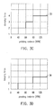
- FIGS. 3A to 3D are graphic views illustrating relational curves of damping according to the first embodiment.
- FIGS. 4A and 4B are block diagrams illustrating an automatic control shock absorber system for a bicycle according to a second embodiment.
- FIGS. 5A to 5D are graphic views illustrating relational curves of damping according to the second embodiment.
- FIG. 6 is a block diagram illustrating an automatic control shock absorber system for a bicycle according to a third embodiment.
- FIGS. 7A to 7C are graphic views illustrating relational curves of damping according to the third embodiment.
- FIGS. 8A to 8C are graphic views illustrating another relational curve of damping according to the third embodiment.
- FIG. 9 is a block diagram illustrating an automatic control shock absorber system for a bicycle according to a fourth embodiment.
- FIGS. 10A to 10C are graphic views illustrating relational curves of damping according to the fourth embodiment.
- FIGS. 11A to 11C are graphic views illustrating another relational curve of damping according to the fourth embodiment.
- FIGS. 12A to 12C are curve diagrams illustrating relations between a crank angle and pedaling power, pedaling force, and pedaling torque, respectively.
- FIG. 13 is a schematic view illustrating a relational curve of damping based on an angular velocity.
- FIG. 14 is a schematic view illustrating a relational curve of damping based on variation frequency of pedaling power, pedaling force, and pedaling torque.
- FIGS. 15A to 15D are schematic views illustrating relational curves of damping based on power.
- FIGS. 16A and 16B are schematic views illustrating pedaling postures.
- FIG. 17 is a block diagram illustrating an automatically adjusting damping system for a bicycle according to a fifth embodiment.
- FIG. 18 is a schematic view illustrating a vibration signal according to the fifth embodiment.
- FIG. 19 is a flowchart illustrating an automatically adjusting damping method for a bicycle according to the fifth embodiment.
- FIG. 20 is a block diagram illustrating an automatically adjusting damping system for a bicycle according to a sixth embodiment.
- FIG. 21 is a flowchart illustrating an automatically adjusting damping method for a bicycle according to the sixth embodiment.
- FIG. 22 is a block diagram illustrating an automatically adjusting damping system for a bicycle according to a seventh embodiment.
- FIG. 23 is a flowchart illustrating an automatically adjusting damping method for a bicycle according to the seventh embodiment.
- FIG. 24 is a block diagram illustrating an automatically adjusting damping system for a bicycle according to an eighth embodiment.
- FIG. 25 is a flowchart illustrating an automatically adjusting damping method for a bicycle according to the eighth embodiment.
- FIG. 26 is a block diagram illustrating an automatically adjusting damping system for a bicycle according to a ninth embodiment.
- FIG. 27 is a flowchart illustrating an automatically adjusting damping method for a bicycle according to the ninth embodiment.
- FIG. 28 is a block diagram illustrating an automatically adjusting damping system for a bicycle according to a tenth embodiment.
- FIG. 29 is a flowchart illustrating an automatically adjusting damping method for a bicycle according to the tenth embodiment.
- FIG. 30 is a curve diagram illustrating a curve of gravity value according to the tenth embodiment.
- FIG. 31 is a flow chart describing one embodiment of a process for automatically adjusting the damper of a shock system based on cadence, vibration and posture.
- the technology disclosed herein provides an automatic control shock absorber system for a bicycle capable of adjusting characteristics of the shock absorber in correspondence with different external factors, so as to improve the pedaling efficiency.
- an algorithm is implemented to calculate vibration of a body of the bicycle within a time period, so as to automatically adjust a level of a damping force based on the vibration of the bicycle itself, thereby improving the pedaling efficiency and preventing the damper from functioning erroneously.
- FIG. 1 is a schematic view illustrating a bicycle.
- a bicycle 10 includes a frame 100 , a front fork 101 , a chain ring 103 , a crank spindle 104 , a crank arm 105 , a pedal 106 , a saddle 107 , a saddle post 108 , a hub (i.e. a shaft at the center of a wheel) 109 , a grip 110 , a handle stem 111 , and a bicycle handle 112 .
- the bicycle 10 also includes a front fork shock absorber 11 (disposed at the front fork 101 ) and a rear shock absorber 12 .
- FIG. 2 is a block diagram illustrating an automatic control shock absorber system for a bicycle according to the first embodiment.
- an automatic control shock absorber system 200 for a bicycle includes a pedaling cadence sensor 210 , a signal receiver 220 , a controller 230 , and a damping adjuster 240 .
- the pedaling cadence sensor 210 is configured to detect a pedaling cadence of the bicycle 10 and output a pedaling signal.
- the pedaling cadence sensor 210 may be disposed at one of the chain ring 103 , the crank spindle 104 , the crank arm 105 , the pedal 106 , and the frame 100 , etc., of the bicycle 10 .
- the pedaling cadence sensor 210 may also be disposed at a leg, such as both legs (e.g. inner sides of thighs) of the rider, or on a shoe of the rider.
- the signal receiver 220 is coupled to the pedaling cadence sensor 210 and the controller 230 to receive and transmit the pedaling signal to the controller 230 .
- the signal receiver 220 may receive and transmit signals through a wire or wirelessly.
- the controller 230 is coupled to the signal receiver 220 and the damping adjuster 240 .
- the controller 230 outputs a level control signal according to the pedaling signal, so as to control a level of a damping force.
- the controller 230 is capable of controlling compression damping, rebound damping, or an air pressure of a pneumatic spring.
- the controller 230 may also control a gear of a transmission or a tire pressure simultaneously.
- the controller 230 may be disposed at a position L1 or a position L2 as indicated in FIG. 1 .
- the positions L1 and L2 only serve as an example.
- the controller 230 may be disposed at an arbitrary position of the bicycle 10 .
- the damping adjuster 240 is coupled to the controller 230 so as to adjust the level of the damping force according to level control signal.
- the damping adjuster 240 is disposed in each of the front fork shock absorber 11 and the rear shock absorber 12 shown in FIG. 1 .
- the controller 230 may control damping forces of the front fork shock absorber 11 and the rear shock absorber 12 simultaneously or control the damping force of only one of the front fork shock absorber 11 and the rear shock absorber 12 .
- FIGS. 3A to 3D are schematic views illustrating relational curves of damping that can be implemented as part of the first embodiment.
- a relational curve of damping 31 shown in FIG. 1 has a damping force positively correlated with the pedaling cadence, and as the pedaling cadence increases, the damping force increases linearly.
- Relational curves of damping 32 - 34 illustrate that as the pedaling cadence increases, the damping force increases in a stepwise manner.
- FIG. 3B illustrates a five-stage adjustment
- FIG. 3C illustrates a four-stage adjustment
- FIG. 3D illustrates a three-stage adjustment.
- X-axis represents the pedaling cadence, with revolutions per minute (RPM) serving as the unit.
- Y-axis represents the damping force of the shock absorber.
- levels 1 to 5 are described herein as an example.
- the number of level represents an extent to which a valve of compression damping is closed. As the number of level increases, the valve of compression damping becomes more closed. Specifically, level 1 indicates that the valve of compression damping is fully open, level 2 indicates that the valve of compression damping is 75% open (i.e. the valve is 25% closed), level 3 indicates that the valve of compression damping is 50% open (i.e. the valve is 50% closed), level 4 indicates that the valve of compression damping is 25% open (i.e. the valve is 75% closed), and level 5 indicates that the valve of compression damping is fully closed.
- level 1 indicates that the valve of compression damping is fully open
- level 2 indicates that the valve of compression damping is 75% open (i.e. the valve is 25% closed)
- level 3 indicates that the valve of
- the relational curve of damping 32 shown in FIG. 3B illustrates a five-stage adjustment.
- the damping force is adjusted at level 1.
- the damping force is adjusted at level 2.
- the damping force is adjusted at level 3.
- the pedaling cadence is from 90 RPM to 135 RPM
- the damping force is adjusted at level 4.
- the pedaling cadence exceeds 135 RPM
- the damping force is adjusted at level 5.
- the relational curve of damping 33 shown in FIG. 3C illustrates a four-stage adjustment.
- the damping force is adjusted at level 1.
- the damping force is adjusted at level 2.
- the damping force is adjusted at level 3.
- the damping force is adjusted at level 4.
- the relational curve of damping 34 shown in FIG. 3D illustrates a three-stage adjustment.
- the damping force is adjusted at level 1.
- the damping force is adjusted at level 2.
- the damping force is adjusted at level 3.
- FIGS. 4A and 4B are block diagrams illustrating an automatic control shock absorber system for a bicycle according to the second embodiment.
- an automatic control shock absorber system 400 for a bicycle includes a posture sensor 410 , the signal receiver 220 , the controller 230 , and the damping adjuster 240 .
- components having the same functions as those described in the first embodiment are referred to with the same reference symbols, and description relevant to the components is omitted.
- the posture sensor 410 is configured to detect whether the rider adopts a standing posture or a sitting posture when riding the bicycle 10 , and output a posture signal.
- the signal receiver 220 is coupled to the posture sensor 410 to receive the posture signal.
- the controller 230 is coupled to the signal receiver 220 and output the level control signal to the damping adjuster 240 , such that the damping adjuster 240 adjusts the level of the damping force according to the level control signal.
- the posture sensor 410 may be disposed on one of the saddle 107 , the saddle post 108 , the grip 110 , the bicycle handle 112 , the handle stem 111 , the pedal 106 , the frame 100 , the front fork 101 , the rear shock absorber 12 , the hub 109 , the crank spindle 104 , and the controller 230 , etc., so as to obtain sensing data for judging a pedaling posture of the rider.
- a pressure sensor serving as the posture sensor 410 is described as an example.
- the pressure sensor may be disposed inside the saddle 107 or the saddle post 108 to serve as the posture sensor 410 .
- the posture sensor 410 senses that a force is applied, the pedaling posture is the sitting posture, when the posture sensor 410 does not senses a force being applied, the pedaling posture is the standing posture.
- the pressure sensor may be disposed at each of the left and right pedals 106 , the left and right grips 110 , the left and right bicycle handles 112 , or the handle stem 111 (or any two points of the bicycle where forces are applied) to serve as the posture sensor 410 .
- the posture sensor is not limited thereto.
- the posture sensor 410 may also be an optical sensor, a radar, or other suitable sensors capable of sensing the change of center of gravity and posture of the rider.
- the automatic control shock absorber system 400 for the bicycle may also include the pedaling cadence sensor 210 and the posture sensor 410 simultaneously. Since in actual riding, the pedaling posture of the rider may exhibit a significant change in the center of gravity or significant change of pedaling manners, the bicycle needs to have a function of correspondingly changing a suspension characteristic of the bicycle. Since the rider is about 5 to 10 times heavier than the bicycle, pedaling conditions of the rider need to be taken care of seriously and should not be treated uniformly. Roughly speaking, shock absorbing when pedaling in the standing posture and shock absorbing when pedaling in the sitting posture are different by two times or more. Thus, it is more preferable if the pedaling cadence and pedaling posture are taken into consideration simultaneously.
- the controller 230 may determine a relational curve of damping based on the posture signal, and output the level control signal according to the pedaling signal based on the relational curve of damping. Accordingly, the damping adjuster 240 adjusts the level of the damping force according to the level control signal.
- the pedaling posture includes the standing posture and the sitting posture.
- the controller 230 may determine whether the relational curve of damping is the relational curve for the sitting posture or the relational curve for the standing posture based on the curve control signal.
- the rider may prepare ahead in correspondence to pavement conditions and simultaneously change a manner of riding. For example, when there is an obstacle, the rider may stop pedaling to pass the obstacle at a lower speed (to reduce shaking of the frame).
- the rider may switch the pedaling posture to move the body forward and shift to a lighter gear to change the cadence.
- cornering the rider generally tends to lower the center of gravity and lower the pedaling cadence.
- two relational curves of damping i.e.
- the relational curve for the sitting posture and the relational curve for the standing posture may be provided to correspond to the two different riding postures, i.e. the sitting posture and the standing posture.
- a slope of curve of the relational curve for the standing posture is steeper than that of the relational curve for the sitting posture.
- FIGS. 5A to 5D are graphs illustrating relational curves of damping according to the second embodiment.
- X-axis represents for the pedaling cadence, with revolutions per minute (RPM) serving as the unit.
- Y-axis represents the damping force of the shock absorber.
- the damping force illustrated in FIGS. 5A and 5B are set from level 1 to level 6.
- the damping force may be set from level 1 to level 5, as shown in FIG. 5C , or set from level 1 to level 4, as shown in FIG. 5D . Details regarding the damping force may be referred to the first embodiment. Therefore, no further details in this respect will be reiterated below.
- a relational curve 51 a for the standing posture and a relational curve 51 b for the standing posture make adjustment linearly.
- the relational curve 51 a for the standing posture is chosen, and a corresponding level is selected based on the relational curve 51 a for the standing posture according to the pedaling cadence detected.
- the relational curve 51 b for the sitting posture is chosen, and a corresponding level is selected based on the relational curve 51 b for the standing posture according to the pedaling cadence detected.
- the controller 230 selects the corresponding level 3 based on the relational curve 51 b for the sitting posture 51 b according to the pedaling cadence at 60 RPM, and outputs the level control signal. Accordingly, when receiving the level control signal, the damping adjuster 240 adjusts the damping force to level 3.
- the relational curves for the standing posture and for the sitting posture may increase in a stepwise manner as the pedaling cadence increases, as shown in FIGS. 5B to 5D .
- a relational curve 52 a for the standing posture and a relational curve 52 b for the sitting posture make a six-stage adjustment, where the damping force is set from level 1 to level 6.
- a relational curve 53 a for the standing posture and a relational curve 53 b for the sitting posture make a five-stage adjustment.
- a relational curve 54 a for the standing posture and a relational curve 54 b for the sitting posture make a four-stage adjustment, where the damping force is set from level 1 to level 4.
- judging the pavement conditions according to the rider is faster and more direct, and less prone to errors.
- reaction may be made in advance or simultaneously to correspond to riding scenarios, so as to take care of influences on changes of the center of gravity due to pedaling in the standing and sitting postures.
- the control method incorporating judging the pedaling posture and detecting the pedaling cadence, which further determines a plurality of riding manners such as riding in the sitting posture, the standing postures, etc., offers a more direct, more efficient, and simpler effect.
- FIG. 6 is a block diagram illustrating an automatic control shock absorber system for a bicycle according to the third embodiment.
- An automatic control shock absorber system for a bicycle of the embodiment includes the pedaling cadence sensor and a slope sensor.
- an automatic control shock absorber system 600 for a bicycle includes the pedaling cadence sensor 210 , a slope sensor 610 , the signal receiver 220 , the controller 230 , and the damping adjuster 240 .
- components having the same functions as those described in the first embodiment are referred to with the same reference symbols, and description relevant to the components is omitted.
- the slope sensor 610 is configured to detect a slope of a location of the bicycle 10 and output a slope signal, such that the slope signal is transmitted to the controller 230 through the signal receiver 220 .
- the controller 230 determines a relational curve of damping according to the slope signal, and outputs the level control signal according to the pedaling signal based on the relational curve of damping.
- FIGS. 7A to 7C are schematic views illustrating relational curves of damping according to the third embodiment.
- relational curves shown in FIGS. 7A to 7C are step-like (stage-adjustment).
- X-axis represents the pedaling cadence
- Y-axis represents the damping force of the shock absorber
- level 1 to level 5 are described as an example. Details regarding the damping force may be referred to the first embodiment.
- FIG. 7A shows an uphill relational curve 71
- FIG. 7B shows a flat (or plane) relational curve 72
- FIG. 7C shows a downhill relational curve 73 .
- the uphill relational curve 71 is chosen, and a corresponding level is selected based on the uphill relational curve 71 according to the pedaling cadence detected.
- the slope signal indicates a flat slope
- the flat relational curve 72 is chosen, and a corresponding level is selected based on the flat relational curve 72 according to the pedaling cadence detected.
- the slope signal indicates a downhill
- the downhill relational curve 73 is chosen, and a corresponding level is selected based on the downhill relational curve 73 according to the pedaling cadence detected.
- FIGS. 8A to 8C are schematic views illustrating another relational curve of damping according to the third embodiment.
- relational curves of damping shown in FIGS. 8A to 8C indicate that the damping force is positively correlated with the pedaling cadence.
- X-axis represents the pedaling cadence
- Y-axis represents the damping force of the shock absorber
- level 1 to level 5 are described as an example. Details regarding the damping force may be referred to the first embodiment. Therefore, no further details in this respect will be reiterated below.
- FIG. 8A shows an uphill relational curve 81
- FIG. 8B shows a flat slope relational curve 82
- FIG. 8C shows a downhill relational curve 83 .
- FIG. 9 is a block diagram illustrating an automatic control shock absorber system for a bicycle according to a fourth embodiment.
- an automatic control shock absorber system 900 for a bicycle includes the pedaling cadence sensor 210 , the posture sensor 410 , the slope sensor 610 , the signal receiver 220 , the controller 230 , and the damping adjuster 240 .
- the controller 230 may determine a relational curve of damping according to the posture signal and the slope signal, and output the level control signal according to the pedaling signal based on the relational curve of damping. Accordingly, the damping adjuster 240 adjusts the level of the damping force according to the level control signal.
- FIGS. 10A to 10C are schematic views illustrating relational curves of damping according to the fourth embodiment.
- the damping force is positively correlated with the pedaling cadence (i.e. stepless adjustment) in the relational curves of damping.
- X-axis represents the pedaling cadence
- Y-axis represents the damping force of the shock absorber. Details regarding the damping force may be referred to the first embodiment.
- FIG. 10A illustrates uphill relational curves of damping, including a relational curve 10 _ 1 a for the standing posture and a relational curve 10 _ 1 b for the sitting posture.
- FIG. 10B illustrates flat slope relational curves of damping, including a relational curve 10 _ 2 a for the standing posture and a relational curve 10 _ 2 b for the sitting posture.
- FIG. 10C illustrates downhill relational curves of damping, including a relational curve 10 _ 3 a for the standing posture and a relational curve 10 _ 3 b for the sitting posture.
- FIGS. 11A to 11C are schematic views illustrating another relational curve of damping according to the fourth embodiment.
- X-axis represents the pedaling cadence
- Y-axis represents the damping force of the shock absorber. Details regarding the damping force may be referred to the first embodiment.
- FIG. 11A illustrates uphill relational curves of damping, including a relational curve 11 _ 1 a for the standing posture and a relational curve 11 _ 1 b for the sitting posture.
- FIG. 11B illustrates flat slope relational curves of damping, including a relational curve 11 _ 2 a for the standing posture and a relational curve 11 _ 2 b for the sitting posture.
- FIG. 11C illustrates downhill relational curves of damping, including a relational curve 11 _ 3 a for the standing posture and a relational curve 11 _ 3 b for the sitting posture.
- the controller 230 may choose the curves shown in FIG. 11C , then choose the relational curve 11 _ 3 b for the sitting posture according to the posture signal, and choose the corresponding level 2 based on the pedaling cadence at 70 RPM.
- the pedaling cadence may be obtained from one of a plurality of information generated by sensing the chain ring 103 , the crank arm 105 , the crank spindle 104 , or the pedal 106 .
- the information are, for example, revolutions per minute (RPM), an angular velocity (radian per second), or a variation frequency of pedaling power, pedaling force, or pedaling torque.
- FIGS. 12A to 12C are curve diagrams illustrating relations between a crank angle and pedaling power, pedaling force, and pedaling torque, respectively, according to an embodiment.
- FIG. 12A illustrates a curve diagram between the crank angle and the pedaling power
- FIG. 12B illustrates a curve diagram between the crank angle and the pedaling force
- FIG. 12C illustrates a curve diagram between the crank angle and the pedaling torque.
- FIG. 13 is a graph illustrating a relational curve of damping based on an angular velocity according to an embodiment.
- FIG. 13 illustrates a relational curve of damping for adjusting the level of the damping force according to the angular velocity.
- FIG. 14 illustrates a relational curve of damping for adjusting the level of the damping force according to the variation frequency (Hz) of the pedaling power/pedaling force/pedaling torque.
- FIGS. 15A to 15D are schematic views illustrating relational curves of damping based on power according to an embodiment.
- the relational curve shown in FIG. 15A indicates a stepless adjustment
- the relational curve shown in FIG. 15B indicates a three-stage adjustment
- the relational curve shown in FIG. 15C indicates a four-stage adjustment
- the relational curve shown in FIG. 15D indicates a three-stage adjustment.
- FIGS. 16A and 16B are schematic views illustrating pedaling postures according to an embodiment.
- the pedaling posture shown in FIG. 16A is the sitting posture
- the pedaling posture shown in FIG. 16B is the standing posture.
- the rider may prepare ahead in correspondence to pavement conditions and simultaneously change a manner of riding. For example, when there is an obstacle, the rider may stop pedaling to pass the obstacle at a lower speed (to reduce shaking of the frame).
- the rider may switch the pedaling posture to move the body forward and shift to a lighter gear to change the cadence.
- cornering the rider generally tends to lower the center of gravity and lower the pedaling cadence.
- the damping force may be adjusted according to different pedaling cadences, different pedaling postures, or the slope of the location.
- the factors above may be combined to correspondingly adjust the damping force. In this way, the pedaling efficiency may be significantly improved.
- FIG. 17 is a block diagram illustrating an automatically adjusting damping system for a bicycle according to a fifth embodiment.
- an automatically adjusting damping system 1200 for a bicycle includes a vibration sensor 1210 , the signal receiver 220 , the controller 230 , and the damping adjuster 240 .
- the vibration sensor 1210 may be disposed at a position such as the saddle 107 , the saddle post 108 , the bicycle handle 112 , the handle stem 111 , the frame 100 , the front fork 101 , the rear fork 114 , or the rear shock absorber 12 , etc., of the bicycle 10 .
- the vibration sensor 1210 detects vibration generated by a body of the bicycle 10 , so as to output a corresponding vibration signal.
- the vibration sensor 1210 is a g-sensor, for example.
- the signal receiver 220 is coupled to the vibration sensor 210 and the controller 230 to receive the vibration signal of the vibration sensor 210 and transmit the vibration signal to the controller 230 .
- the signal receiver 220 may receive and transmit signals through a wire or wirelessly.
- the controller 230 is coupled to the signal receiver 220 and the damping adjuster 240 .
- the controller 230 outputs a level control signal according to the vibration signal received, so as to control a level of a damping force of the damping adjuster 240 .
- the controller 230 is capable of controlling compression damping, rebound damping, or an air pressure of a pneumatic spring.
- the controller 230 may also control a gear of a transmission or a tire pressure simultaneously.
- the controller 230 may be disposed at a position L1 or a position L2 as indicated in FIG. 1 . However, the positions L1 and L2 only serve as an example.
- the controller 230 may be disposed at an arbitrary position of the bicycle 10 .
- the damping adjuster 240 is coupled to the controller 230 , so as to adjust the level of the damping force according to the level control signal.
- the damping adjuster 240 may be disposed in each of the front fork shock absorber 11 and the rear shock absorber 12 shown in FIG. 1 .
- the controller 230 may control damping forces of the front fork shock absorber 11 and the rear shock absorber 12 simultaneously or control the damping force of only one of the front fork shock absorber 11 and the rear shock absorber 12 .
- the level of the damping force refers to an extent to which a valve of compression damping is opened.
- a lower level of the damping force indicates that the valve of compression damping is opened more widely than that indicated by a higher level of the damping force.
- the total number of levels may be set to be two or more, such as level 1 to level 2, level 1 to level 3, or level 1 to level 5, etc., based on the actual needs.
- the controller 230 calculates a vibration parameter according to the vibration signal, so as to output the level control signal corresponding to the vibration parameter to the damping adjuster 240 , such that the damping adjuster 240 adjusts the level of the damping force according to the level control signal.
- the vibration parameter is higher, the level of the damping force is adjusted to be lower.
- the vibration parameter is lower, the level of the damping force is adjusted to be higher.
- FIG. 18 is a schematic view illustrating an example of a vibration signal.
- a cycle of time of each sampling is 0.01 seconds, and the number of times of sampling is 8. Accordingly, acceleration differences ⁇ 1 to ⁇ 8 of eight intervals (i.e. I1 to I8) are obtained.
- the vibration parameter (indicated by “V” in the following) is calculated based on the following formula.
- N refers the number of times of sampling for calculating the vibration parameter.
- the level of the damping force may be further determined according to the vibration parameter. In the following, how the level of the damping force is determined is described.
- FIG. 19 is a flowchart illustrating an automatically adjusting damping method for a bicycle according to the fifth embodiment.
- the vibration sensor 1210 detects the vibration generated by the body of the bicycle, so as to output the vibration signal and transmit the vibration signal to the controller 230 through the signal receiver 220 .
- Step S 410 the controller 230 calculates the vibration parameter based on the vibration signal. Calculation of the vibration parameter is referred to the description about FIG. 18 above.
- Step S 415 the controller 230 determines whether the vibration parameter is greater than a vibration threshold value T, so as to output the level control signal corresponding to the vibration parameter to the damping adjuster 240 . If the vibration parameter is not greater than the vibration threshold value T, it is indicated that the bicycle 10 is on a smoother pavement, so the damping force may be increased. Thus, the controller 230 outputs the level control signal for increasing the level of the damping force to the damping adjuster 240 .
- the control processing signal 230 outputs the level control signal for decreasing the level of the damping force to the damping adjuster 240 .
- the damping adjuster 240 sets the level of the damping force at D1 (the first damping level). If the vibration parameter is greater than the vibration threshold value T, at Step S 425 , the damping adjuster 240 sets the level of the damping force at D2 (the second damping level). In addition, D1 is higher than D2.
- FIG. 20 is a block diagram illustrating an automatically adjusting damping system for a bicycle according to a second embodiment.
- An automatically adjusting damping system 1500 for a bicycle is an example of application of the automatically adjusting damping system 1200 for the bicycle.
- components having the same functions as those in the automatically adjusting damping system 1200 for the bicycle are referred to with the same reference symbols, and the description of these components is omitted.
- the automatically adjusting damping system 1500 for the bicycle includes the vibration sensor 1210 , the signal receiver 220 , the controller 230 , the damping adjuster 240 , and the pedaling cadence sensor 210 .
- the pedaling cadence sensor 210 is coupled to the signal receiver 220 and is configured to detect a pedaling cadence of the bicycle 10 and output a pedaling signal.
- the pedaling cadence sensor 210 may be disposed at one of the chain ring 103 , the crank spindle 104 , the crank arm 105 , the pedal 106 , and the frame 100 , etc., of the bicycle 10 .
- the pedaling cadence sensor 510 may also be disposed at a leg, such as both legs (e.g. inner sides of thighs) of a rider, or on a shoe of the rider.
- the controller 230 determines an initial damping level according to the pedaling signal.
- FIG. 21 is a flowchart illustrating an automatically adjusting damping method for a bicycle according to the sixth embodiment.
- the pedaling cadence of the bicycle 10 is detected by using the pedaling cadence sensor 210 , and the pedaling signal is output.
- the controller 230 determines an initial damping level D_ini according to the pedaling signal.
- two threshold values may be set to determine whether the pedaling cadence is in a high-speed state, a normal state, or a low-speed state. It is assumed that the threshold values are th1 and th2, and th2 is greater than th1.
- the initial damping level D_ini is set at D firm .
- the pedaling cadence is lower than or equal to th2 and is higher than or equal to th1
- the state is determined to be the normal state, and the initial damping level D_ini is set at D medium .
- the initial damping level D_ini is set at D soft .
- Step S 615 the vibration sensor 1210 detects the vibration generated by the body of the bicycle, so as to output the vibration signal and transmit the vibration signal to the controller 230 through the signal receiver 220 .
- Step S 620 the controller 230 calculates the vibration parameter based on the vibration signal. Calculation of the vibration parameter is referred to the description about FIG. 3 above.
- Step S 625 the controller 230 determines whether the vibration parameter is greater than the vibration threshold value T, so as to output the level control signal corresponding to the vibration parameter to the damping adjuster 240 .
- FIG. 22 is a block diagram illustrating an automatically adjusting damping system for a bicycle according to a third embodiment.
- An automatically adjusting damping system 1700 for a bicycle is an example of application of the automatically adjusting damping system 1200 for the bicycle.
- components having the same functions as those in the automatically adjusting damping system 1200 for the bicycle are referred to with the same reference symbols, and the description of these components is omitted.
- the automatically adjusting damping system 1700 for the bicycle includes the vibration sensor 1210 , the signal receiver 220 , the controller 230 , the damping adjuster 240 , and the posture sensor 410 .
- the posture sensor 410 is configured to detect whether a posture that the rider adopts when riding the bicycle 10 is a standing pedaling posture or a sitting pedaling posture, and output a posture signal.
- the posture sensor 410 is coupled to the signal receiver 220 , so as to transmit the posture signal to the controller 230 through the signal receiver 220 , such that the controller 230 determines whether the vibration threshold value is T1 or T2 according to the posture signal.
- the posture sensor 410 may be disposed on one of the saddle 107 , the saddle post 108 , the grip 110 , the bicycle handle 112 , the handle stem 111 , the pedal 106 , the frame 100 , the front fork 101 , the rear shock absorber 12 , the hub 109 , and the crank spindle 104 , etc., of the bicycle 10 , so as to obtain sensing data for determining a pedaling posture of the rider.
- a pressure sensor serving as the posture sensor 410 is described as an example.
- the pressure sensor may be disposed inside the saddle 107 or the saddle post 108 to serve as the posture sensor 710 .
- the posture sensor 410 senses that a force is applied, the pedaling posture is the sitting pedaling posture, when the posture sensor 410 does not senses a force being applied, the pedaling posture is the standing pedaling posture.
- the pressure sensor may be disposed at each of the left and right pedals 106 , the left and right grips 110 , the bicycle handle 112 , or the handle stem 111 (or any two points of the bicycle where forces are applied) to serve as the posture sensor 410 .
- the posture sensor 410 is not limited thereto.
- the posture sensor 410 may also be an optical sensor or a radar, or other suitable sensors capable of sensing the change of center of gravity and posture of the rider.
- the rider may prepare ahead in correspondence to pavement conditions and simultaneously change a manner of riding. For example, when there is an obstacle, the rider may stop pedaling to pass the obstacle at a lower speed (to reduce shaking of the body). During uphill riding, the rider may switch the pedaling posture to move the body forward and shift to a lighter gear to change the cadence. During cornering, the rider generally tends to lower the center of gravity and lower the pedaling cadence.
- two sets of parameters may be set in correspondence with the standing pedaling posture and the sitting pedaling posture, and each set of the parameters includes the vibration threshold value and two damping levels.
- the vibration threshold value is T1
- the damping levels are respectively D_11 and D_12.
- the vibration threshold value is T2
- the damping levels are respectively D_13 and D_14.
- T1 and T2 described herein may be the same or different.
- FIG. 23 is a flowchart illustrating an automatically adjusting damping method for a bicycle according to the third embodiment.
- the vibration sensor 1210 detects the vibration generated by the body of the bicycle 10 , so as to output the vibration signal and transmit the vibration signal to the controller 230 through the signal receiver 220 .
- the controller 230 calculates the vibration parameter based on the vibration signal.
- Step S 815 the posture sensor 410 is used to detect whether the posture that the rider adopts when riding the bicycle 10 is the standing pedaling posture or the sitting pedaling posture, and output the corresponding posture signal, such that the controller 230 sets whether the vibration threshold value is T1 or T2 according to the posture signal.
- Step S 815 may be performed before or together with Step S 805 .
- a sequence for performing Step S 815 is not limited herein.
- the controller 230 determines whether the vibration parameter is greater than the vibration threshold value T1 at Step S 820 . If the vibration parameter is not greater than the vibration threshold value T1, at Step S 825 , the damping adjuster 240 sets the level of the damping force at D_11 (the first damping level). If the vibration parameter is greater than the vibration threshold value T1, at Step S 830 , the damping adjuster 240 sets the level of the damping force at D_12 (the second damping level). In addition, D_11 is higher than D_12.
- the controller 230 determines whether the vibration parameter is greater than the vibration threshold value T2 at Step S 835 . If the vibration parameter is not greater than the vibration threshold value T2, at Step S 840 , the damping adjuster 240 sets the level of the damping force at D_13 (the third damping level). If the vibration parameter is greater than the vibration threshold value T2, at Step S 845 , the damping adjuster 240 sets the level of the damping force at D_14 (the fourth damping level). In addition, D_13 is higher than D_14. Also, since the center of gravity of the rider's body is less stable when the standing pedaling posture is adopted, the standing pedaling posture requires a higher damping level. Thus, it is preferred to simultaneously set that D_13 ⁇ D_11, and D_14 ⁇ D_12.
- FIG. 24 is a block diagram illustrating an automatically adjusting damping system for a bicycle according to an eighth embodiment.
- An automatically adjusting damping system 1900 for a bicycle is an example of application of the automatically adjusting damping system 1200 for the bicycle.
- components having the same functions as those in the automatically adjusting damping system 1200 for the bicycle are referred to with the same reference symbols, and the description of these components is omitted.
- the automatically adjusting damping system 1900 for the bicycle includes the vibration sensor 1210 , the signal receiver 220 , the controller 230 , the damping adjuster 240 , and the slope sensor 610 .
- the slope sensor 610 is configured to detect whether a slope of a current location of the bicycle 10 indicates uphill and output a corresponding slope signal to transmit the slope signal to the controller 230 through the signal receiver 220 , such that the controller 230 sets whether the vibration threshold value is T3 or T4 according to the slope signal.
- FIG. 25 is a flowchart illustrating an automatically adjusting damping method for a bicycle according to the eighth embodiment.
- the vibration sensor 1210 detects the vibration generated by the body of the bicycle 10 , so as to output the vibration signal and transmit the vibration signal to the controller 230 through the signal receiver 220 .
- the controller 230 calculates the vibration parameter according to the vibration signal.
- Step S 1015 the slope sensor 610 is used to detect whether the slope of the location of the bicycle 10 indicates uphill, and output the corresponding slope signal, such that the controller 230 sets whether the vibration threshold value is T3 or T4 according to the slope signal.
- Step S 1015 may be performed before or together with Step S 1005 .
- a sequence for performing Step S 1015 is not limited herein. T3 and T4 described herein may be the same or different.
- the controller 230 determines whether the vibration parameter is greater than the vibration threshold value T3 at Step S 1020 . If the vibration parameter is not greater than the vibration threshold value T3, at Step S 1025 , the damping adjuster 240 sets the level of the damping force at D_21 (the first damping level). If the vibration parameter is greater than the vibration threshold value T3, at Step S 1030 , the damping adjuster 240 sets the level of the damping force at D_22 (the second damping level). In addition, D_21 is higher than D_22.
- the controller 230 determines whether the vibration parameter is greater than the vibration threshold value T4 at Step S 1035 . If the vibration parameter is not greater than the vibration threshold value T4, at Step S 1040 , the damping adjuster 240 sets the level of the damping force at D_23 (the third damping level). If the vibration parameter is greater than the vibration threshold value T4, at Step S 1045 , the damping adjuster 240 sets the level of the damping force at D_24 (the fourth damping level). In addition, D_23 is higher than D_24. It is preferred to also set that D_23 ⁇ D_21, and D_24 ⁇ D_22.
- FIG. 26 is a block diagram illustrating an automatically adjusting damping system for a bicycle according to a ninth embodiment.
- An automatically adjusting damping system 1902 for a bicycle is an example of application of the automatically adjusting damping system 1200 for the bicycle.
- components having the same functions as those described in the above embodiments are referred to with the same reference symbols, and description relevant to the components is omitted.
- the automatically adjusting damping system 1902 for the bicycle includes the vibration sensor 1210 , the signal receiver 220 , the controller 230 , the damping adjuster 240 , the pedaling cadence sensor 210 , and the posture sensor 410 .
- FIG. 27 is a flowchart illustrating an automatically adjusting damping method for a bicycle according to the ninth embodiment.
- the pedaling cadence of the bicycle 10 is detected by using the pedaling cadence sensor 210 , and the pedaling signal is output.
- the posture sensor 410 is used to detect whether the posture that the rider adopts when riding the bicycle is the standing pedaling posture or the sitting pedaling posture, and output the corresponding posture signal.
- a sequence for performing Step S 1205 and Step S 1210 is not limited herein.
- Step S 1215 the controller 230 determines the initial damping level D_ini according to the pedaling signal and the posture signal. For example, different values are respectively set as the initial damping level D_ini according to postures when the pedaling cadence are in the high-speed state, the normal state, and the low-speed state.
- the vibration sensor 1210 detects the vibration generated by the body of the bicycle 10 .
- the controller calculates the vibration parameter according to the vibration signal. Calculation of the vibration parameter is referred to the description above with respect to FIG. 18 .
- the controller 230 determines whether the vibration parameter is greater than the vibration threshold value T, so as to output the level control signal corresponding to the vibration parameter to the damping adjuster 240 . If the vibration parameter is not greater than the vibration threshold value T, at Step S 1235 , the damping adjuster 240 sets the level of the damping force at D1 (the first damping level).
- FIG. 28 is a block diagram illustrating an automatically adjusting damping system for a bicycle according to a tenth embodiment.
- An automatically adjusting damping system 1904 for a bicycle is an example of application of the automatically adjusting damping system 1200 for the bicycle.
- the automatically adjusting damping system 1904 for the bicycle includes the vibration sensor 1210 , the signal receiver 220 , the controller 230 , the damping adjuster 240 , the pedaling cadence sensor 210 , the posture sensor 410 , and the slope sensor 610 .
- FIG. 29 is a flowchart illustrating an automatically adjusting damping method for a bicycle according to the tenth embodiment.
- the pedaling cadence of the bicycle 10 is detected by using the pedaling cadence sensor 210 , and the pedaling signal is output.
- the posture sensor 410 is used to detect whether the posture that the rider adopts when riding the bicycle 10 is the standing pedaling posture or the sitting pedaling posture, and output the corresponding posture signal.
- the slope sensor 910 is used to detect whether the slope of the current location of the bicycle 10 indicates uphill, and output the corresponding slope signal.
- a sequence for performing Step S 1405 , Step 1410 , and Step 1415 is not limited herein.
- Step S 1420 the controller 230 determines the initial damping level D_ini according to the pedaling signal, the posture signal, and the slope signal.
- the vibration sensor 1210 detects the vibration generated by the body of the bicycle 10 .
- the controller 230 calculates the vibration parameter according to the vibration signal. Calculation of the vibration parameter is referred to the description about FIG. 18 above.
- the controller 230 determines whether the vibration parameter is greater than the vibration threshold value T, so as to output the level control signal corresponding to the vibration parameter to the damping adjuster 240 .
- the system may further set a threshold gravity value, so as to determine whether the bicycle is in a weightless state.
- a gravity value sensed by the gravity sensor is lower than the threshold gravity value for a predetermined time tp, the controller 230 may automatically adjust the level of the damping force to the minimal damping level.
- FIG. 30 is a curve diagram illustrating an example curve of gravity value.
- the controller 230 may make the damping adjuster 240 set the level of the damping force at the minimal damping level. For example, the controller 230 may drive the valve of compression damping to be fully open.
- FIG. 31 is a flow chart describing one embodiment of a process for automatically adjusting the damper of a shock system based on cadence, vibration and posture.
- the flow chart of FIG. 31 applies to the embodiment of FIG. 26 ; however, the flow chart of FIG. 31 can apply to other embodiment of structure.
- step S 1502 the process starts.
- step S 1504 the damper for the shock absorber is open. In one example, the damper is completely open. In another example, the damper is open to the softest setting.
- step S 1506 the data from the cadence sensor 210 is received and analyzed.
- step S 1504 If the signal from the cadence sensor 210 is below (or equal to) a threshold, then the process is complete, the damper stay open and the method loops back to step S 1504 . If the signal from the cadence sensor 210 is greater the threshold, then the data from vibration sensor 1210 is considered in step S 1508 . If the vibration sensor indicates that the bicycle is flying (ie in a weightless state), then the process is complete, the damper stay open and the method loops back to step S 1504 . If the data from vibration sensor does not indicate that the bicycle is flying and the data from vibration sensor is less than or equal to a threshold, then data from posture sensor 410 is considered in step S 1510 . If the data from vibration sensor does not indicate that the bicycle is flying and the data from vibration sensor is greater than a threshold, then data from posture sensor 410 is considered in step S 1520 .
- step S 1510 it is determined whether data from posture sensor 410 indicates that the rider is sitting or standing. If the rider is standing, then the Damper is set to a value of Da in step S 1512 . If the rider is sitting, then the Damper is set to a value of Db in step S 1514 .
- step S 1520 it is determined whether data from posture sensor 410 indicates that the rider is sitting or standing. If the rider is standing, then the Damper is set to a value of Dc in step S 1522 . If the rider is sitting, then the Damper is set to a value of Dd in step S 1524 . Note that (Da ⁇ Db) AND (Dc ⁇ Dd) AND (Da ⁇ Dc) AND (Db ⁇ Dd).
- the vibration sensor is disposed on the bicycle to detect the shock from the pavement to the body of the bicycle.
- the controller is also disposed on the bicycle to calculate the vibration of the body of the bicycle according to the shock of the body of the bicycle and logically determine whether to increase or decrease the level of the damping force.
- the pedaling efficiency may be increased, so that the power exerted by the rider may be transmitted to the bicycle in a more effective way.
- the comfort and control may be increased, so as to improve the safety of riding.
- switching of the level of the damping force of the damper is automatically and logically determined, the rider does not need to pay attention to manually control the switching. Therefore, the convenience and the safety are both improved.
Landscapes
- Engineering & Computer Science (AREA)
- Mechanical Engineering (AREA)
- Axle Suspensions And Sidecars For Cycles (AREA)
- Fluid-Damping Devices (AREA)
- Vehicle Body Suspensions (AREA)
Applications Claiming Priority (6)
| Application Number | Priority Date | Filing Date | Title |
|---|---|---|---|
| TW102141089A | 2013-11-12 | ||
| TW102141089A TWI537175B (zh) | 2013-11-12 | 2013-11-12 | 自行車自動控制避震器系統 |
| TW102141089 | 2013-11-12 | ||
| TW103126190 | 2014-07-31 | ||
| TW103126190A | 2014-07-31 | ||
| TW103126190A TWI507318B (zh) | 2014-07-31 | 2014-07-31 | 自行車自動調整阻尼系統 |
Publications (2)
| Publication Number | Publication Date |
|---|---|
| US20150130153A1 US20150130153A1 (en) | 2015-05-14 |
| US9676441B2 true US9676441B2 (en) | 2017-06-13 |
Family
ID=51868895
Family Applications (1)
| Application Number | Title | Priority Date | Filing Date |
|---|---|---|---|
| US14/534,152 Active 2035-02-13 US9676441B2 (en) | 2013-11-12 | 2014-11-05 | Automatic shock absorber system for bicycle |
Country Status (8)
| Country | Link |
|---|---|
| US (1) | US9676441B2 (fr) |
| EP (1) | EP2871082B1 (fr) |
| JP (1) | JP5964928B2 (fr) |
| AU (1) | AU2014262175B2 (fr) |
| CA (1) | CA2870644C (fr) |
| DK (1) | DK2871082T3 (fr) |
| ES (1) | ES2680593T3 (fr) |
| PL (1) | PL2871082T3 (fr) |
Cited By (6)
| Publication number | Priority date | Publication date | Assignee | Title |
|---|---|---|---|---|
| US20190061851A1 (en) * | 2017-08-23 | 2019-02-28 | Shimano Inc. | Electric seatpost assembly |
| DE102020100276A1 (de) | 2020-01-09 | 2021-07-15 | Shimano Inc. | Federungssteuersystem für die federung eines mit menschenkraft angetriebenen fahrzeugs |
| US11912363B2 (en) | 2019-02-22 | 2024-02-27 | Shimano Inc. | Control device for telescopic apparatus |
| US12128920B2 (en) | 2023-04-03 | 2024-10-29 | Roadio, Inc. | Method and system for producing an environmental awareness for alerting an operator of a vehicle |
| US20240375741A1 (en) * | 2021-08-31 | 2024-11-14 | SR Suntour Europe GmbH | Damper control arrangement |
| US12354373B2 (en) | 2023-04-03 | 2025-07-08 | Roadio, Inc. | Method and system for providing a rider with a dynamic environmental awareness |
Families Citing this family (27)
| Publication number | Priority date | Publication date | Assignee | Title |
|---|---|---|---|---|
| US9216791B2 (en) * | 2011-03-14 | 2015-12-22 | Christopher Hudec | Bicycle suspension system |
| TWI564204B (zh) * | 2014-08-13 | 2017-01-01 | 巨大機械工業股份有限公司 | 騎乘姿勢偵測裝置 |
| DE102015107707A1 (de) * | 2015-05-18 | 2016-11-24 | Dt Swiss Ag | Fahrwerksteuerung für ein muskelbetriebenes Zweirad |
| JP3200367U (ja) * | 2015-07-29 | 2015-10-15 | 株式会社シマノ | 自転車用制御装置およびこれを備える自転車用制御システム |
| JP5950268B1 (ja) * | 2016-01-31 | 2016-07-13 | サーチウェア株式会社 | 自転車の制御システム |
| JPWO2018051827A1 (ja) * | 2016-09-16 | 2019-06-24 | パイオニア株式会社 | 荷重推定装置 |
| JP7236799B2 (ja) | 2017-07-11 | 2023-03-10 | 株式会社シマノ | 自転車用制御装置およびこれを備える自転車用サスペンションシステム |
| JP6610626B2 (ja) | 2017-08-03 | 2019-11-27 | カシオ計算機株式会社 | 活動状況解析装置、活動状況解析方法及びプログラム |
| JP6645481B2 (ja) | 2017-08-03 | 2020-02-14 | カシオ計算機株式会社 | 活動記録データ処理装置、活動記録データ処理方法及び活動記録データ処理プログラム |
| JP6686985B2 (ja) | 2017-08-03 | 2020-04-22 | カシオ計算機株式会社 | 軌跡推定装置、軌跡推定方法及び軌跡推定プログラム |
| JP7343266B2 (ja) * | 2017-10-27 | 2023-09-12 | 株式会社シマノ | 人力駆動車両用制御装置 |
| JP7194905B2 (ja) * | 2018-01-19 | 2022-12-23 | パナソニックIpマネジメント株式会社 | 電動自転車及びその制御方法 |
| JP6964013B2 (ja) * | 2018-02-20 | 2021-11-10 | 株式会社シマノ | 人力駆動車の制御装置、緩衝システム、および、人力駆動車 |
| JP6736596B2 (ja) * | 2018-03-16 | 2020-08-05 | 本田技研工業株式会社 | 車両 |
| JP6863921B2 (ja) * | 2018-03-22 | 2021-04-21 | 株式会社シマノ | 人力駆動車両用制御装置 |
| EP3818342B1 (fr) | 2018-07-02 | 2023-08-30 | Rasei Ltd | Article et et procédé permettant de surveiller ou de commander le fonctionnement d'un article mobile |
| JP6985217B2 (ja) | 2018-07-09 | 2021-12-22 | 株式会社シマノ | 制御データ作成装置、コンポーネント制御装置、制御データ作成方法、コンポーネント制御方法、およびコンピュータプログラム |
| KR102056762B1 (ko) | 2018-12-03 | 2019-12-16 | 한림대학교 산학협력단 | 딥러닝 기반 맥락인식 댐퍼 제어 동계스포츠 시스템 |
| US11713093B2 (en) * | 2019-08-29 | 2023-08-01 | Fox Factory, Inc. | Smart device application with customizable tunes for active valve control |
| US11459050B2 (en) | 2019-09-03 | 2022-10-04 | Fox Factory, Inc. | Connected component platform |
| WO2021046240A1 (fr) * | 2019-09-03 | 2021-03-11 | Fox Factory, Inc. | Plate-forme à composants connectés |
| US12134296B2 (en) * | 2020-04-24 | 2024-11-05 | Sram, Llc | Adjustable suspension components for bicycles |
| DE102020210867A1 (de) * | 2020-08-28 | 2022-03-03 | Robert Bosch Gesellschaft mit beschränkter Haftung | Vorrichtung und Verfahren zum Erfassen einer an einem Fahrrad vorliegenden Trittfrequenz |
| JP2022176850A (ja) * | 2021-05-17 | 2022-11-30 | 株式会社シマノ | 人力駆動車用の制御装置 |
| DE102022202815A1 (de) | 2022-03-23 | 2023-09-28 | Zf Friedrichshafen Ag | Vibrationsüberwachung an einem Fahrradlader |
| US20250074529A1 (en) * | 2023-08-29 | 2025-03-06 | C-Tech United Corporation | Auxiliary assembly for bicycle |
| US20250256804A1 (en) * | 2024-02-09 | 2025-08-14 | Shimano Inc. | Detection system, detection method, and computer-readable storage medium |
Citations (21)
| Publication number | Priority date | Publication date | Assignee | Title |
|---|---|---|---|---|
| US4881750A (en) | 1989-02-06 | 1989-11-21 | Hartmann Dirck T | ATB shock absorber |
| US5217246A (en) | 1989-04-24 | 1993-06-08 | Group Lotus Plc | Control system for controlling the suspension of a land vehicle |
| US5445401A (en) | 1993-09-07 | 1995-08-29 | Manitou Mountain Bikes, Inc. | Suspension fork for bicycles |
| US5456480A (en) | 1994-06-06 | 1995-10-10 | Rockshox, Inc. | Fork suspension with variable hydraulic damping |
| US5975225A (en) | 1993-02-24 | 1999-11-02 | Deka Products Limited Partnership | Transportation vehicles with stability enhancement using CG modification |
| US6026939A (en) | 1997-05-15 | 2000-02-22 | K2 Bike Inc. | Shock absorber with stanchion mounted bypass damping |
| US6149174A (en) | 1997-01-13 | 2000-11-21 | Bohn; David D. | Electronically controlled bicycle suspension apparatus |
| US20020180166A1 (en) * | 2001-04-03 | 2002-12-05 | Voss Darrell W. | Vehicles and methods using center of gravity and mass shift control system |
| US20060064223A1 (en) * | 2004-09-20 | 2006-03-23 | Darrell Voss | Vehicle systems and method |
| US7128192B2 (en) * | 2001-08-30 | 2006-10-31 | Fox Factory, Inc. | Inertia valve shock absorber |
| US20090088934A1 (en) * | 2007-09-28 | 2009-04-02 | Shimano Inc. | Bicycle control system |
| US20100276906A1 (en) * | 2009-05-04 | 2010-11-04 | Mario Galasso | Suspension system for a vehicle |
| US20110012317A1 (en) * | 2009-07-17 | 2011-01-20 | Shimano Inc. | Bicycle suspension having stroke and damper adjustment |
| US20110095507A1 (en) * | 2008-04-02 | 2011-04-28 | Pierre-Geoffroy Plantet | Bicycle suspension system |
| US20110109060A1 (en) * | 2009-08-31 | 2011-05-12 | Praxis Works LLC | Active shock-damping system |
| US20110202236A1 (en) * | 2009-03-19 | 2011-08-18 | Mario Galasso | Methods and apparatus for suspension adjustment |
| US20120253599A1 (en) * | 2011-03-30 | 2012-10-04 | Shimano Inc. | Bicycle suspension control apparatus |
| US8403092B1 (en) * | 2010-05-07 | 2013-03-26 | Mark Trethewey | Motorcycle suspension system |
| US8825322B1 (en) | 2013-04-15 | 2014-09-02 | Shimano Inc. | Bicycle component controlling apparatus |
| US20140316652A1 (en) * | 2009-01-07 | 2014-10-23 | Fox Factory, Inc. | Method and apparatus for an adjustable damper |
| US20150081171A1 (en) * | 2009-01-07 | 2015-03-19 | Fox Factory, Inc. | Method and apparatus for an adjustable damper |
Family Cites Families (12)
| Publication number | Priority date | Publication date | Assignee | Title |
|---|---|---|---|---|
| JPS6082494A (ja) * | 1983-10-13 | 1985-05-10 | 株式会社昭和製作所 | リヤ−クツシヨンオ−ト減衰力可変装置 |
| DE4108905A1 (de) * | 1991-03-19 | 1992-09-24 | Dietrich Gerhard Ellsaesser | Adaptives daempfersystem |
| JPH06135215A (ja) * | 1992-10-27 | 1994-05-17 | Toyota Motor Corp | 減衰力可変式ショックアブソーバのステップモータ制御装置 |
| US5971116A (en) * | 1997-03-13 | 1999-10-26 | Cannondale Corporation | Electronic suspension system for a wheeled vehicle |
| US6543799B2 (en) * | 2000-01-13 | 2003-04-08 | Shimano Inc. | Bicycle suspension |
| JP2002225776A (ja) * | 2001-02-01 | 2002-08-14 | Shimano Inc | 自転車用サスペンションシステム及びユニット |
| DE10242447A1 (de) * | 2002-09-11 | 2004-03-25 | Sartorius Ag | Sensorik und Verfahren zur Messung von Kräften auf ein Fahrrad |
| JP4643490B2 (ja) * | 2006-05-23 | 2011-03-02 | 株式会社豊田中央研究所 | 車両用サスペンション装置 |
| EP2757030B1 (fr) * | 2008-01-24 | 2015-12-23 | Cycling Sports Group, Inc. | Système d'interface utilisateur de bicyclette et son procédé de fonctionnement |
| US8091910B2 (en) * | 2009-06-29 | 2012-01-10 | Shimano, Inc. | Apparatus for controlling a bicycle suspension element |
| DE102010055828A1 (de) * | 2010-12-23 | 2012-06-28 | Dt Swiss Ag | Fahrwerksteuerung für ein Fahrrad |
| DE102012212949A1 (de) * | 2012-07-24 | 2014-01-30 | Robert Bosch Gmbh | Verfahren und Vorrichtung zur Steuerung einer Dämpfung eines durch den Fahrer antreibbaren Fahrzeugs |
-
2014
- 2014-11-05 US US14/534,152 patent/US9676441B2/en active Active
- 2014-11-10 CA CA2870644A patent/CA2870644C/fr active Active
- 2014-11-11 DK DK14192632.9T patent/DK2871082T3/en active
- 2014-11-11 PL PL14192632T patent/PL2871082T3/pl unknown
- 2014-11-11 AU AU2014262175A patent/AU2014262175B2/en active Active
- 2014-11-11 EP EP14192632.9A patent/EP2871082B1/fr active Active
- 2014-11-11 ES ES14192632.9T patent/ES2680593T3/es active Active
- 2014-11-11 JP JP2014228910A patent/JP5964928B2/ja active Active
Patent Citations (24)
| Publication number | Priority date | Publication date | Assignee | Title |
|---|---|---|---|---|
| US4881750A (en) | 1989-02-06 | 1989-11-21 | Hartmann Dirck T | ATB shock absorber |
| US5217246A (en) | 1989-04-24 | 1993-06-08 | Group Lotus Plc | Control system for controlling the suspension of a land vehicle |
| US5975225A (en) | 1993-02-24 | 1999-11-02 | Deka Products Limited Partnership | Transportation vehicles with stability enhancement using CG modification |
| US5445401A (en) | 1993-09-07 | 1995-08-29 | Manitou Mountain Bikes, Inc. | Suspension fork for bicycles |
| US5509677A (en) | 1993-09-07 | 1996-04-23 | Manitou Mountain Bikes, Inc. | Suspension fork for bicycles with dual, fluid-based dampers |
| US5456480A (en) | 1994-06-06 | 1995-10-10 | Rockshox, Inc. | Fork suspension with variable hydraulic damping |
| US6149174A (en) | 1997-01-13 | 2000-11-21 | Bohn; David D. | Electronically controlled bicycle suspension apparatus |
| US6026939A (en) | 1997-05-15 | 2000-02-22 | K2 Bike Inc. | Shock absorber with stanchion mounted bypass damping |
| US20020180166A1 (en) * | 2001-04-03 | 2002-12-05 | Voss Darrell W. | Vehicles and methods using center of gravity and mass shift control system |
| US7350787B2 (en) | 2001-04-03 | 2008-04-01 | Voss Darrell W | Vehicles and methods using center of gravity and mass shift control system |
| US7128192B2 (en) * | 2001-08-30 | 2006-10-31 | Fox Factory, Inc. | Inertia valve shock absorber |
| US20060064223A1 (en) * | 2004-09-20 | 2006-03-23 | Darrell Voss | Vehicle systems and method |
| US20090088934A1 (en) * | 2007-09-28 | 2009-04-02 | Shimano Inc. | Bicycle control system |
| US20110095507A1 (en) * | 2008-04-02 | 2011-04-28 | Pierre-Geoffroy Plantet | Bicycle suspension system |
| US8286982B2 (en) | 2008-04-02 | 2012-10-16 | Cycles Lapierre | Bicycle suspension system |
| US20140316652A1 (en) * | 2009-01-07 | 2014-10-23 | Fox Factory, Inc. | Method and apparatus for an adjustable damper |
| US20150081171A1 (en) * | 2009-01-07 | 2015-03-19 | Fox Factory, Inc. | Method and apparatus for an adjustable damper |
| US20110202236A1 (en) * | 2009-03-19 | 2011-08-18 | Mario Galasso | Methods and apparatus for suspension adjustment |
| US20100276906A1 (en) * | 2009-05-04 | 2010-11-04 | Mario Galasso | Suspension system for a vehicle |
| US20110012317A1 (en) * | 2009-07-17 | 2011-01-20 | Shimano Inc. | Bicycle suspension having stroke and damper adjustment |
| US20110109060A1 (en) * | 2009-08-31 | 2011-05-12 | Praxis Works LLC | Active shock-damping system |
| US8403092B1 (en) * | 2010-05-07 | 2013-03-26 | Mark Trethewey | Motorcycle suspension system |
| US20120253599A1 (en) * | 2011-03-30 | 2012-10-04 | Shimano Inc. | Bicycle suspension control apparatus |
| US8825322B1 (en) | 2013-04-15 | 2014-09-02 | Shimano Inc. | Bicycle component controlling apparatus |
Cited By (8)
| Publication number | Priority date | Publication date | Assignee | Title |
|---|---|---|---|---|
| US20190061851A1 (en) * | 2017-08-23 | 2019-02-28 | Shimano Inc. | Electric seatpost assembly |
| US11001323B2 (en) * | 2017-08-23 | 2021-05-11 | Shimano Inc. | Electric seatpost assembly |
| US11912363B2 (en) | 2019-02-22 | 2024-02-27 | Shimano Inc. | Control device for telescopic apparatus |
| DE102020100276A1 (de) | 2020-01-09 | 2021-07-15 | Shimano Inc. | Federungssteuersystem für die federung eines mit menschenkraft angetriebenen fahrzeugs |
| US11884357B2 (en) | 2020-01-09 | 2024-01-30 | Shimano Inc. | Suspension control system for suspension of human-powered vehicle |
| US20240375741A1 (en) * | 2021-08-31 | 2024-11-14 | SR Suntour Europe GmbH | Damper control arrangement |
| US12128920B2 (en) | 2023-04-03 | 2024-10-29 | Roadio, Inc. | Method and system for producing an environmental awareness for alerting an operator of a vehicle |
| US12354373B2 (en) | 2023-04-03 | 2025-07-08 | Roadio, Inc. | Method and system for providing a rider with a dynamic environmental awareness |
Also Published As
| Publication number | Publication date |
|---|---|
| JP2015093671A (ja) | 2015-05-18 |
| AU2014262175A1 (en) | 2015-05-28 |
| DK2871082T3 (en) | 2018-09-03 |
| JP5964928B2 (ja) | 2016-08-03 |
| US20150130153A1 (en) | 2015-05-14 |
| PL2871082T3 (pl) | 2018-12-31 |
| EP2871082B1 (fr) | 2018-05-30 |
| ES2680593T3 (es) | 2018-09-10 |
| EP2871082A3 (fr) | 2015-07-15 |
| AU2014262175B2 (en) | 2016-07-21 |
| CA2870644A1 (fr) | 2015-05-12 |
| EP2871082A2 (fr) | 2015-05-13 |
| CA2870644C (fr) | 2017-12-19 |
Similar Documents
| Publication | Publication Date | Title |
|---|---|---|
| US9676441B2 (en) | Automatic shock absorber system for bicycle | |
| US9540067B2 (en) | Automatic shock absorber system for a bicycle | |
| EP4021029B1 (fr) | Dispositif à faible latence et à faible consommation pour un composant actif pour un composant actif | |
| TWI819297B (zh) | 用於自行車之可調式懸吊組件 | |
| KR101980913B1 (ko) | 차량용 서스펜션 제어 장치 | |
| TWI823265B (zh) | 定向柔性顛簸感測器和用於校準定向柔性顛簸感測器的方法 | |
| US11584473B2 (en) | Suspension control device for a human-powered vehicle | |
| JP6546675B2 (ja) | 電子可変サスペンションシステム | |
| JP2015221641A (ja) | 自転車用電動構成部品 | |
| US20230081873A1 (en) | Wireless active suspension system with at least one wireless sensor coupled with at least one unsprung mass | |
| CN107097892A (zh) | 自行车自动控制避震器系统 | |
| JP2010195232A (ja) | 減衰力制御装置、及び減衰力制御方法 | |
| TWI537175B (zh) | 自行車自動控制避震器系統 | |
| JP5224058B2 (ja) | サスペンション制御装置 | |
| TWI507318B (zh) | 自行車自動調整阻尼系統 | |
| CN114684321A (zh) | 人力驱动车的控制装置 | |
| TWI838241B (zh) | 針對電動助力自行車之自動控制系統及方法 | |
| JP7848049B2 (ja) | 制御装置 | |
| JPWO2013172464A1 (ja) | 鞍乗型車両及び鞍乗型車両の制御方法 | |
| TWI904810B (zh) | 針對驅動車的部件調整裝置以及方法 | |
| JP7847475B2 (ja) | 制御装置 | |
| US20250360769A1 (en) | Hot-start suspension tune | |
| TWM664315U (zh) | 針對驅動車的部件調整裝置 | |
| JP2022103027A (ja) | 人力駆動車の制御装置 | |
| JPH115420A (ja) | 車両懸架装置 |
Legal Events
| Date | Code | Title | Description |
|---|---|---|---|
| AS | Assignment |
Owner name: GIANT MANUFACTURING CO. LTD., TAIWAN Free format text: ASSIGNMENT OF ASSIGNORS INTEREST;ASSIGNORS:CHEN, CHIEN-HUNG;CHEN, MIN-CHANG;LIN, CHUNG-WEI;REEL/FRAME:034115/0949 Effective date: 20141104 |
|
| STCF | Information on status: patent grant |
Free format text: PATENTED CASE |
|
| MAFP | Maintenance fee payment |
Free format text: PAYMENT OF MAINTENANCE FEE, 4TH YEAR, LARGE ENTITY (ORIGINAL EVENT CODE: M1551); ENTITY STATUS OF PATENT OWNER: LARGE ENTITY Year of fee payment: 4 |
|
| MAFP | Maintenance fee payment |
Free format text: PAYMENT OF MAINTENANCE FEE, 8TH YEAR, LARGE ENTITY (ORIGINAL EVENT CODE: M1552); ENTITY STATUS OF PATENT OWNER: LARGE ENTITY Year of fee payment: 8 |