US9719822B2 - Method of ultrasonic flow measurement and device for the implementation of the method - Google Patents
Method of ultrasonic flow measurement and device for the implementation of the method Download PDFInfo
- Publication number
- US9719822B2 US9719822B2 US14/003,165 US201214003165A US9719822B2 US 9719822 B2 US9719822 B2 US 9719822B2 US 201214003165 A US201214003165 A US 201214003165A US 9719822 B2 US9719822 B2 US 9719822B2
- Authority
- US
- United States
- Prior art keywords
- transducer
- array
- acoustic
- kaf
- δtc
- Prior art date
- Legal status (The legal status is an assumption and is not a legal conclusion. Google has not performed a legal analysis and makes no representation as to the accuracy of the status listed.)
- Active, expires
Links
- 238000005259 measurement Methods 0.000 title claims abstract description 48
- 238000000034 method Methods 0.000 title claims abstract description 34
- 238000012545 processing Methods 0.000 claims description 23
- 238000004364 calculation method Methods 0.000 claims description 16
- 239000012530 fluid Substances 0.000 claims description 16
- 238000004458 analytical method Methods 0.000 claims description 14
- 238000005314 correlation function Methods 0.000 claims description 8
- 230000006870 function Effects 0.000 claims description 8
- 230000002123 temporal effect Effects 0.000 claims description 4
- 238000013461 design Methods 0.000 description 10
- 230000000694 effects Effects 0.000 description 8
- 238000002474 experimental method Methods 0.000 description 5
- 238000006073 displacement reaction Methods 0.000 description 4
- 238000009434 installation Methods 0.000 description 4
- 229910000831 Steel Inorganic materials 0.000 description 3
- 230000007423 decrease Effects 0.000 description 3
- 229910001220 stainless steel Inorganic materials 0.000 description 3
- 239000010935 stainless steel Substances 0.000 description 3
- 239000010959 steel Substances 0.000 description 3
- 238000000691 measurement method Methods 0.000 description 2
- 238000012935 Averaging Methods 0.000 description 1
- 230000006399 behavior Effects 0.000 description 1
- 230000005540 biological transmission Effects 0.000 description 1
- 230000003111 delayed effect Effects 0.000 description 1
- 238000003745 diagnosis Methods 0.000 description 1
- 238000004519 manufacturing process Methods 0.000 description 1
- 239000000463 material Substances 0.000 description 1
- 238000012544 monitoring process Methods 0.000 description 1
- 230000008054 signal transmission Effects 0.000 description 1
- 238000013519 translation Methods 0.000 description 1
- 230000001960 triggered effect Effects 0.000 description 1
Images




Classifications
-
- G—PHYSICS
- G01—MEASURING; TESTING
- G01F—MEASURING VOLUME, VOLUME FLOW, MASS FLOW OR LIQUID LEVEL; METERING BY VOLUME
- G01F1/00—Measuring the volume flow or mass flow of fluid or fluent solid material wherein the fluid passes through a meter in a continuous flow
- G01F1/66—Measuring the volume flow or mass flow of fluid or fluent solid material wherein the fluid passes through a meter in a continuous flow by measuring frequency, phase shift or propagation time of electromagnetic or other waves, e.g. using ultrasonic flowmeters
-
- G—PHYSICS
- G01—MEASURING; TESTING
- G01F—MEASURING VOLUME, VOLUME FLOW, MASS FLOW OR LIQUID LEVEL; METERING BY VOLUME
- G01F1/00—Measuring the volume flow or mass flow of fluid or fluent solid material wherein the fluid passes through a meter in a continuous flow
- G01F1/66—Measuring the volume flow or mass flow of fluid or fluent solid material wherein the fluid passes through a meter in a continuous flow by measuring frequency, phase shift or propagation time of electromagnetic or other waves, e.g. using ultrasonic flowmeters
- G01F1/662—Constructional details
-
- G—PHYSICS
- G01—MEASURING; TESTING
- G01F—MEASURING VOLUME, VOLUME FLOW, MASS FLOW OR LIQUID LEVEL; METERING BY VOLUME
- G01F1/00—Measuring the volume flow or mass flow of fluid or fluent solid material wherein the fluid passes through a meter in a continuous flow
- G01F1/66—Measuring the volume flow or mass flow of fluid or fluent solid material wherein the fluid passes through a meter in a continuous flow by measuring frequency, phase shift or propagation time of electromagnetic or other waves, e.g. using ultrasonic flowmeters
- G01F1/667—Arrangements of transducers for ultrasonic flowmeters; Circuits for operating ultrasonic flowmeters
-
- G—PHYSICS
- G01—MEASURING; TESTING
- G01F—MEASURING VOLUME, VOLUME FLOW, MASS FLOW OR LIQUID LEVEL; METERING BY VOLUME
- G01F1/00—Measuring the volume flow or mass flow of fluid or fluent solid material wherein the fluid passes through a meter in a continuous flow
- G01F1/66—Measuring the volume flow or mass flow of fluid or fluent solid material wherein the fluid passes through a meter in a continuous flow by measuring frequency, phase shift or propagation time of electromagnetic or other waves, e.g. using ultrasonic flowmeters
- G01F1/667—Arrangements of transducers for ultrasonic flowmeters; Circuits for operating ultrasonic flowmeters
- G01F1/668—Compensating or correcting for variations in velocity of sound
-
- G01F25/0007—
-
- G—PHYSICS
- G01—MEASURING; TESTING
- G01F—MEASURING VOLUME, VOLUME FLOW, MASS FLOW OR LIQUID LEVEL; METERING BY VOLUME
- G01F25/00—Testing or calibration of apparatus for measuring volume, volume flow or liquid level or for metering by volume
- G01F25/10—Testing or calibration of apparatus for measuring volume, volume flow or liquid level or for metering by volume of flowmeters
Definitions
- Clamp-on flow meters are widely used in numerous industrial sectors. One of their major advantages is the fact that the flow measurement takes place without any contact with the flowing fluid.
- the acoustic transducers used for the clamp-on flow measurement consist of a transducer wedge and a thereon mounted electromechanical acoustic transducer element, hereinafter referred to as transducer element, which is generally realized using a piezoceramic element.
- the acoustic transducers are mounted on the outside of the pipe in which the flow rate is to be measured.
- the pipe is referred to as measuring pipe.
- the acoustic transducers are positioned in such way that an ultrasonic signal can be sent through the measuring pipe by one acoustic transducer to the other acoustic transducer and the acoustic beam in the flowing fluid has an angle smaller than 90 in relation to the pipe axis.
- Clamp-on flow meters measure the difference of the transit times of the two acoustic signals that propagate in and against the flow direction and use the transit time difference to calculate the volumetric flow rate.
- the relationship between the measured transit times and the flow velocity is described, for example, in WO 8808516 A1.
- alpha and c_alpha correspond to the angle of incidence and the sound speed in the transducer wedge, respectively.
- KF the fluidmechanical calibration factor
- the ultrasonic clamp-on flow measurement is described, for example, in DE19808642. Due to the design of the cross-section area of the pipe, the fluidmechanical calibration factor KF is designed in such way that it is independent of the condition of the flow. In DE10312034B3, an ultrasonic flow measurement method is described which allows a particularly precise determination of the fluid transit time t 1 by measuring consecutive ultrasonic signals which pass through the measuring pipe multiple times.
- EP0733885A1 describes a method for ultrasonic clamp-on flowmeters of compensating for the pressure and temperature dependence of the fluid by determining the sound speed of the fluid and adjusting the sound path within the fluid according to the law of refraction.
- the sound speeds of the transducer wedge and the pipe wall with their temperature dependences are assumed as known.
- DE102009046871A1 describes a method of calibrating the transmitter of an ultrasonic clamp-on flowmeter. This allows a calibration of the time measurement required according to Eq. 1 which is independent of the acoustic properties of the measuring pipe and the acoustic transducers. Using this method, the transducer constant Ka is assumed as known and invariable.
- the angle of incidence in the fluid is determined according to the law of refraction from the transducer constant Ka and the sound speed in the fluid.
- the wall of the measuring pipe can lead to a non-negligible deviation from sound propagation according to the law of refraction.
- the transducer constant Ka used in Eq. (1) does not exactly represent the ratio of the flow velocity Vl and the transit time difference ⁇ t as well as the transit time t 1 instead of the transducer constant Ka calculated from the parameters of the acoustic transducer in Eq. (2), it would be necessary to use a factor containing the influence of the pipe wall in Eq. (1). This factor could generally be called acoustic calibration factor.
- a major advantage of the clamp-on flow measurement is the fact that the acoustic transducers can be installed on a pipe already present at the measuring point. If this advantage is to be utilized, the flowmeter cannot be calibrated at the manufacturing site together with the measuring pipe. Therefore, a possible influence of the measuring pipe on the acoustic calibration factor has to be compensated for after the installation of the acoustic transducers at the measuring point on the measuring pipe. For this, it is necessary to quantify this influence, i.e., to determine the acoustic calibration factor mentioned previously.
- the determination of a calibration factor for a flowmeter which is already located at the measuring point is called field calibration. In the process, the value displayed by the flowmeter is compared with the value displayed by a reference flowmeter. Usually, however, there is no reference flowmeter present at the measuring point. Therefore, it is preferable to determine the acoustic calibration factor without relying on a reference flowmeter.
- DE 10221771 A1 shows an acoustic transducer for an ultrasonic flowmeter with multiple piezo elements which are combined to form a piezo array.
- an array is a number of transducer elements arranged in a plane, where the transducer elements can be triggered independently and, when combined, also form a transducer element.
- the transducer elements which form the array are called array elements.
- the array elements are piezo elements. Therefore, it is possible, by using an acoustic transducer attached flatly to the measuring pipe wall, to achieve different angles of incidence into the measured fluid for the ultrasonic signal with one wave front in relation to the measuring pipe axis.
- delayed triggering requires a lot of computational power.
- the change of angle is only possible within a limited range. If the angle of incidence of the ultrasonic signal is very flat, longitudinal waves can be excited, which can lead to a decrease in the transmission through the pipe wall and to the reflection of a significant part of the sound wave.
- DE 102008029772 A1 describes a measuring system and a method for determining and/or monitoring the flow rate of a measured fluid in a measuring pipe using a first acoustic transducer and at least a second acoustic transducer.
- the second acoustic transducer is equipped with at least two transducer elements.
- the signals obtained during a diagnosis phase are used to select the transducer elements of the second acoustic transducer to be used during the measurement phase. By doing this, it is possible, for example, to reduce the effect of a sound speed change that might occur after the installation. A field calibration is not possible with this method.
- the invention is based on the objective of creating a clamp-on flow measurement method and a device for implementing the method which compensates for the deviation of the acoustic calibration factor caused by the measuring pipe, which does not rely on a reference flowmeter and during which the acoustic transducers can remain in their installation position on the measuring pipe.
- this objective is accomplished by a method of ultrasonic clamp-on flow measurement using two acoustic transducers with transducer elements which are installed on a measuring pipe, where at least one transducer element includes at least two array elements, characterized in that during an analysis phase consisting of the following steps
- a calibration factor Kaf is determined using the calculated time difference delta_tc and used during the subsequent operating phase for the measurement of a volumetric flow rate Q in order to compensate for the acoustic influence of the measuring pipe.
- An alternative solution consists in a method of ultrasonic clamp-on flow measurement using two acoustic transducers with transducer elements which are installed on a measuring pipe where at least one transducer element includes at least two array elements and is characterized in that, during an analysis phase, a cross-correlation function of at least two received signals (s 1 ) and (s 2 ) is calculated, where the received signal (s 1 ) is the signal emitted by the transducer element ( 3 ) of the first acoustic transducer ( 1 ) and received and digitized by the array element ( 4 a ) of the second acoustic transducer ( 2 ), and the received signal (s 2 ) is the signal emitted by the transducer element ( 3 ) of the first acoustic transducer ( 1 ) and received and digitized by the array element ( 4 b ) of the second acoustic transducer ( 2 ), the temporal position of the maximum of the cross-correlation function is calculated
- a calculation of a path length difference delta_lc is carried out based on the time difference delta_tc, where a known sound speed ca in the transducer wedge is multiplied by the time difference delta_tc, resulting in an angle change delta_alpha with arcsin(delta_lc/delta_s), where delta_s is the mutual distance of the array elements ( 4 a ) and ( 4 b ), from which the calibration factor Kaf is calculated as ca/sin(alpha+delta_alpha).
- the calibration factor Kaf is calculated from the time difference delta_tc using an approximation function fc(delta_tc), where the approximation function fc(delta_tc) is calculated from a number N of value pairs (Kaf_i, delta_tc_i), where the value pairs (Kaf_i, delta_tc_i) are obtained before the measurement by measuring Kaf_i and delta_tc_i on each of a number N of pipes i, on which the acoustic transducers are installed in the way customary to the ultrasonic clamp-on flow measurement, where the measurement of Kaf_i is carried out by measuring the transit times tx 1 and tx 2 , while the acoustic transducer ( 2 ) is located at the position x 1 or x 2 , where the transit times are the transit times between a transducer element ( 3 ) of the first acoustic transducer ( 1 ) and a transducer element ( 4 ) of the
- the method can be implemented in a clamp-on flowmeter.
- the device for the implementation of the method includes an emitting unit, at least one array multiplexer with at least 2 inputs, a direction switch, a receiving amplifier, a processing unit and a control unit and a calculation unit and is characterized in that the array multiplexer connects either an array element 4 a or an array element 4 b or both array elements to a receiving amplifier and the control unit controls the direction switch as well as the array multiplexer and the processing unit, which determines the time difference delta_tc, and the calculation unit, which determines the calibration factor Kaf from the time difference delta_tc and uses it during the operating phase.
- the processing unit includes an analog-to-digital converter, a buffer memory and a digital correlator.
- the correlator is realized by using a programmable digital signal processor.
- the processing unit includes a time measuring unit, a buffer memory and a difference generator.
- An advantage of the method and the device for the implementation of the method is the fact that the flowmeter can be calibrated without a reference volumetric flow rate.
- the acoustic transducers can remain in their installation position.
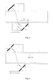
- FIG. 1 acoustic transducer arrangement on the measuring pipe
- FIG. 2 acoustic transducer arrangement on the measuring pipe, where the transducer element of the acoustic transducer 2 is realized as an array,
- FIG. 3 acoustic transducer arrangement on the measuring pipe, where the transducer element of the acoustic transducer 2 is realized as an array,
- FIG. 4 acoustic transducer arrangement on a measuring pipe, Error! Reference source not found.: acoustic transducer arrangement on the measuring pipe, where the transducer element of both acoustic transducers is realized as an array,
- FIG. 6 circuit arrangement for the implementation of the method
- FIG. 7 processing unit
- FIG. 8 another design variation of the processing unit
- FIG. 9 other designs of the acoustic transducer as an array with another array multiplexer.
- FIG. 1 shows such a plane wave front 6 .
- the measuring pipe is assumed to be axisymmetrical with regard to its geometry and material properties. Therefore, the pipe wall limits shown in the sectional plane in FIG. 1 are parallel to each other. Therefore, if a wave is emitted by the acoustic transducer 1 and propagates through the pipe to the acoustic transducer 2 , the angles of incidence in both transducer wedges are equal.
- the idea behind the invention is to measure this deviation from parallelism of the wave front to the transducer element of the acoustic transducer receiving the sound wave from the transit time differences which occur along the geometry of the receiving transducer element.
- FIG. 2 shows such an arrangement. It differs from the arrangement shown in FIG. 1 in that the transducer element of the acoustic transducer 2 is designed as an array with the array elements 4 a and 4 b .
- the direction of propagation of the wave front 6 is changed by the measuring pipe in such way that it does not arrive parallel to the transducer element of the acoustic transducer 2 .
- the drawing of the change of the angle is exaggerated. The effect is usually so small that it would not be visible in FIG. 2 .
- the transit time t 1 between the transducer element 3 of the first acoustic transducer 1 and the array element 4 a of a second acoustic transducer 2 as well as the transit time t 2 between the transducer element 3 of the first acoustic transducer 1 and the array element 4 b of the second acoustic transducer 2 are measured.
- the two transit times t 1 and t 2 are therefore measured and the time difference delta_tc is calculated to obtain a measured value of the time difference delta_tc.
- the measured value of the time difference is used to determine a calibration factor Kaf.
- the flow measurement is carried out.
- the calibration factor determined during the analysis phase is used to compensate for the acoustic influence of the measuring pipe.
- the transducer constant Ka in Eq. (4) is replaced by Kaf.
- the two array elements 4 a and 4 b of the transducer element 4 are electrically connected in parallel.
- the two combined array elements of the transducer element 4 form a transducer element of the same size as the transducer element 3 . Due to the parallel connection, the transducer element 4 has about the same acoustic properties as the transducer element 3 .
- One advantageous embodiment of the invention is obtained by determining the time difference delta_tc directly from the received signals without a previous measurement of the transit times t 1 and t 2 .
- the cross correlation function of the received signals s 1 and s 2 is calculated, where s 1 is the signal emitted by the transducer element 3 of the first acoustic transducer 1 and received and digitized by the array element 4 a of the second acoustic transducer 2 , and s 2 is the signal emitted by the transducer element 3 of the first acoustic transducer 1 and received and digitized by the array element 4 b of the second acoustic transducer 2 .
- a difference of the transit times of the two signals manifests itself in a displacement of the maximum of the cross-correlation function by exactly this difference.
- the time difference delta_tc can therefore be determined by determining the maximum of the cross-correlation function of the signals s 1 and s 2 .
- the path length difference delta_tc is calculated as the time difference delta_tc multiplied by the sound speed ca in the transducer wedge.
- Delta_ tc ca *delta_ tc Eq. (6)
- delta_s is the distance between the array elements as defined in FIG. 2 .
- the imagined displacement of the array element 4 a by the distance delta_x as shown in FIG. 3 causes a transit time difference of the propagation of sound between the transducer element 3 and the array element 4 a by the value delta_tx.
- the transit time t 2 is instead measured and used to calculate the transit time t 20 between the transducer element 3 and the array element 4 at the imagined position.
- the transit time t 20 is obtained by from t 2 by subtracting the transit time ta along the distance delta_i through the transducer wedge.
- t 20 t 2 ⁇ ta Eq. (10)
- Eq. (8) and Eq. (18) are alternative ways to describe the calibration factor Kaf.
- Kaf The difference between Kaf and the transducer constant Ka, which results only from the properties of the transducer, is caused by the effect of the pipe wall.
- Eq. (8) yields the same result as Eq. (18). Namely, Eq. (8) can be converted to Eq. (18) by approximating sin(alpha+delta_alpha) using the first term of the Taylor series and substituting arcsin(delta_lc/delta_s) with the argument delta_lc/delta_s.
- Kaf can be determined using the method described in DE 102004031274 B4. This method is applied in a laboratory to a sufficient choice of measuring pipes which are possible in practical applications. For this, the acoustic transducers are positioned on pipe 5 as shown in Error! Reference source not found. Then, the transit times tx 1 and tx 2 at the positions x 1 and x 2 of the acoustic transducer 2 are measured, where the points x 1 and x 2 lie symmetrically with respect to a point x 0 .
- the transit times tx 1 and tx 2 are the transit times between the transducer element 3 of the acoustic transducer 1 and the transducer element 4 of the acoustic transducer 2 .
- the two array elements 4 a and 4 b of the transducer element 4 are electrically connected in parallel.
- the acoustic transducer 2 is placed at position x 0 and the time difference delta_tc is measured. This yields a value pair Kaf_i and delta_tc_i for the pipe i used in the experiment.
- the experiment is repeated for a number N of additional pipe segments which are selected in such way that the extent of their influence on the calibration factor varies. This yields a number N of value pairs (Kaf_i, delta_tc_i). Applying a common method, these value pairs are used to calculate an approximation function fc(delta_tc) suitable to approximate Kaf from delta_tc.
- the function fc serves to cover as much as possible of the variation range of Kaf which can occur in practice.
- the variation range of the properties of the pipes used in the experiment has to correspond to that of the pipes present in the practical application of the flowmeter.
- the acoustic transducers are suitable for steel and stainless steel pipes with pipe wall thicknesses between 4 and 8 mm, one possibility would be to conduct the experiment on pipes with the pipe wall thicknesses 4, 6 and 8 mm for both steel and stainless steel.
- the data base can be extended by conducting the experiment using different steel or stainless steel grades with varying elastic properties.
- the transducer element 4 shown in FIG. 2 does not consist of two but four array elements. Therein, two non-adjacent array elements can be connected in parallel.
- the value delta_x decreases to one fourth of the total width of the array.
- Each of the transducer elements created by this interconnection has 3 ⁇ 4 of the width of the array, meaning that the area representing its aperture is also 3 ⁇ 4 of the interconnection of all array elements of the array used for the flow measurement.
- the number of array elements can be continued in the manner described. With the increasing number of array elements, the transducer element used during the analysis phase becomes more similar to the interconnection of all array elements used for the flow measurement. On the other hand, the time difference delta_tc, which causes a certain deviation of the angle of the wave front decreases, meaning that it can be measured less exactly.
- the properties of the two acoustic transducers used in a flow measurement arrangement according to the time difference principle should be as similar as possible in order to minimize the zero offset error.
- One advantageous embodiment of the invention results from the fact that, during the operating phase, the two array elements 4 a and 4 b are connected in parallel and, by doing this, the size of the transducer element of the acoustic transducer 2 is made largely identical to that of the acoustic transducer 1 . Furthermore, it is possible to realize the transducer element 3 of the acoustic transducer 1 as an array. One such arrangement is shown in FIG. 4 .
- the array elements 3 a and 3 b of the transducer element of the acoustic transducer 1 are connected in parallel during the analysis phase as well as during the operating phase.
- the electromechanical properties of the transducer elements of the acoustic transducers 1 and 2 are largely identical.
- the measurement of the time difference delta_tc is only intended to measure the influence of the deviation of the wave front from parallelism to the receiving transducer element.
- the transit time of the sound is also influenced by the flow.
- the flow velocity is constant during the measurement of t 1 and t 2 , the flow has no effect on the difference.
- this is never achieved in an ideal manner.
- the flow is mostly in a turbulent state. In this case, the flow velocity randomly fluctuates around a mean value.
- the influence of such random fluctuations in case of a constant mean value of the flow velocity can be eliminated by averaging several successive measured values of the time difference.
- the mean value of the flow velocity is not constant, this procedure will not help.
- a time-linear increase of the flow velocity results in that the flow velocity has a systematically greater influence on the transit time t 1 than on the transit time t 2 .
- the pause times between the individual measurements should be kept as short as possible. This procedure can also be applied to the present invention. Obviously, the effect of the change of flow is smaller if the time intervals between the measurements of t 1 and t 2 are shorter.
- a device consisting of an emitting unit S, at least one array multiplexer AMUX, a direction switch DMUX, a receiving amplifier V, a processing unit SPU and a control unit CTRL and a calculation unit CALC is proposed ( FIG. 6 ).
- the array multiplexer AMUX connects either the array element 4 a or the array element 4 b or both array elements to the receiving amplifier V.
- the control unit CTRL controls the direction switch DMUX and the array multiplexer AMUX as well as the processing unit SPU and the calculation unit CALC.
- the direction switch DMUX is switched in such way that the emitting unit S is connected to the terminals of the acoustic transducer 1 and its corresponding transducer element, and the receiving amplifier V is connected to the array multiplexer AMUX.
- the array multiplexer AMUX is controlled in such way either only the array element 4 a or the array element 4 b of the acoustic transducer 2 is connected to the receiving amplifier V.
- the processing unit SPU connected to the receiving amplifier V determines the time difference delta_tc to be measured.
- the processing unit SPU shown in FIG. 7 includes an analog-to-digital converter ADC, a buffer memory MEM and a correlator KORR.
- the array element 4 a is connected to the processing unit SPU via the array multiplexer AMUX and the receiving amplifier, and an emitted signal is generated by the emitting unit S.
- the received signal generated at the array element 4 a is digitized by the analog-to-digital converter ADC in the processing unit SPU and stored in the buffer memory MEM.
- the array multiplexer AMUX is switched by the control unit CTRL in such way that the array element 4 b is connected to the processing unit SPU via the receiving amplifier V and another emitted signal is generated by the emitting unit S.
- the received signal generated at the array element 4 b is digitized by the analog-to-digital converter ADC in the processing unit SPU and also stored in the buffer memory MEM.
- the time difference delta_tc is directly determined from the received signals of the array elements 4 a and 4 b which have been digitized and stored in the buffer memory.
- This digital correlator KORR is realized using, for example, a programmable digital signal processor (DSP).
- the calibration factor Kaf is calculated by the calculation unit CALC from the time difference delta_tc determined in the correlator according to Eq. 8 or Eq. 18.
- the processing unit SPU includes a time measurement unit TDC with a very high resolution, e.g., a “time-to-digital converter”, and a buffer memory MEM.
- TDC time measurement unit
- the transit time t 1 or t 2 is measured directly without digitizing, using the corresponding received signal, and stored in the buffer memory MEM. After the two transit times t 1 and t 2 have been measured, their difference is calculated by the difference generator MINUS and transmitted to the calculation unit CALC to determine the calibration factor Kaf.
- the array multiplexer AMUX is switched by the control unit CTRL in such way that the array elements 4 a and 4 b are connected in parallel.
- the direction switch DMUX alternately operates the acoustic transducer 1 as an emitter and the acoustic transducer 2 as a receiver, and the acoustic transducer 2 as an emitter and the acoustic transducer 1 as a receiver.
- the processing unit SPU is now used to measure the transit time difference ⁇ t caused by the flow and the transit time in the fluid t 1 , and uses them to calculate the flow rate according to Eq. 4 in the calculation unit CALC, where the transducer constant Ka is substituted by the calibration factor Kaf determined during the analysis phase.
- the transducer element of the acoustic transducer 1 is also realized as an array and another array multiplexer AMUX 2 is added between the terminals of the acoustic transducer 1 and the direction switch DMUX.
- the two array multiplexers AMUX and AMUX 2 are controlled in such way that the array elements 3 a and 3 b as well as the array elements 4 a and 4 b are connected in parallel.
- one of the array multiplexers is controlled in such way that the corresponding array elements are connected in parallel, while the other multiplexer realizes the subsequent connection of the array elements to the receiving amplifier V and the processing unit SPU.
- At least one of the transducer elements 3 and 4 is made up of more than two array elements.
- the corresponding array multiplexer of the devices according to FIG. 6 and FIG. 9 contains as many inputs as array elements.
- the corresponding array multiplexer is controlled in such way that, as a first step, at least 2 non-adjacent array elements are connected in parallel and their received signal is processed.
- the other and non-adjacent array elements are connected in parallel and their received signal is processed.
Landscapes
- Physics & Mathematics (AREA)
- Fluid Mechanics (AREA)
- General Physics & Mathematics (AREA)
- Electromagnetism (AREA)
- Measuring Volume Flow (AREA)
- Ultra Sonic Daignosis Equipment (AREA)
Applications Claiming Priority (4)
| Application Number | Priority Date | Filing Date | Title |
|---|---|---|---|
| DE102011005170.8 | 2011-03-07 | ||
| DE102011005170A DE102011005170B4 (de) | 2011-03-07 | 2011-03-07 | Verfahren zur Ultraschall-Clamp-on-Durchflussmessung und Vorrichtung zur Umsetzung des Verfahrens |
| DE102011005170 | 2011-03-07 | ||
| PCT/EP2012/053909 WO2012120039A2 (de) | 2011-03-07 | 2012-03-07 | Verfahren zur ultraschall-clamp-on-durchflussmessung und vorrichtung zur umsetzung des verfahrens |
Publications (2)
| Publication Number | Publication Date |
|---|---|
| US20140000339A1 US20140000339A1 (en) | 2014-01-02 |
| US9719822B2 true US9719822B2 (en) | 2017-08-01 |
Family
ID=45952459
Family Applications (1)
| Application Number | Title | Priority Date | Filing Date |
|---|---|---|---|
| US14/003,165 Active 2034-05-23 US9719822B2 (en) | 2011-03-07 | 2012-03-07 | Method of ultrasonic flow measurement and device for the implementation of the method |
Country Status (6)
| Country | Link |
|---|---|
| US (1) | US9719822B2 (ja) |
| EP (1) | EP2684010B1 (ja) |
| JP (1) | JP6043904B2 (ja) |
| CN (1) | CN103429996B (ja) |
| DE (1) | DE102011005170B4 (ja) |
| WO (1) | WO2012120039A2 (ja) |
Families Citing this family (15)
| Publication number | Priority date | Publication date | Assignee | Title |
|---|---|---|---|---|
| JP2015232519A (ja) * | 2014-06-10 | 2015-12-24 | アズビル株式会社 | クランプオン式超音波流量計及び流量の計測方法 |
| DE102014109772B3 (de) | 2014-07-11 | 2015-09-24 | Flexim Flexible Industriemesstechnik Gmbh | Messkopfanklemmung für Ultraschall-Durchflussmess-Messköpfe |
| DE102014115203B3 (de) * | 2014-10-20 | 2016-03-24 | Flexim Flexible Industriemesstechnik Gmbh | Verfahren und Anordnung zur Ultraschall-Clamp-on-Durchflussmessung und Schaltungsanordnung zur Steuerung einer Ultraschall-Clamp-on-Durchflussmessung |
| DE102015107753A1 (de) * | 2015-05-18 | 2016-11-24 | Endress + Hauser Flowtec Ag | Verfahren zur Ermittlung einer charakteristischen Größe zur Bewertung einer Messanordnung umfassend ein Clamp-On-Ultraschall- Durchflussmessgerät und ein Rohr und/oder zur Bewertung des Messbetriebs dieser Messanordnung |
| DE102015107750A1 (de) | 2015-05-18 | 2016-11-24 | Endress + Hauser Flowtec Ag | Meßsystem zum Messen wenigstens eines Parameters eines Fluids |
| EP3308595B1 (en) * | 2015-06-10 | 2021-08-18 | Telefonaktiebolaget LM Ericsson (publ) | Establishing an interaction session on a bearer in a radio communication network |
| KR101806306B1 (ko) * | 2015-10-19 | 2017-12-08 | 숭실대학교산학협력단 | 파이프의 두께 측정을 기초로 한 유속 측정 장치 |
| DE102016119180A1 (de) | 2016-10-10 | 2018-04-12 | Endress + Hauser Flowtec Ag | Gehäuse für ein Feldgerät der Mess- und Automatisierungstechnik zur Überwachung und/oder Bestimmung mindestens einer Prozessgröße eines Mediums |
| CN106768103B (zh) * | 2016-12-07 | 2019-02-12 | 浙江威星智能仪表股份有限公司 | 一种超声波流量计自动校准时间偏差的方法 |
| KR102026362B1 (ko) | 2018-08-01 | 2019-09-27 | 서울대학교산학협력단 | Meta slab을 적용한 유속 측정용 초음파 트랜스듀서 |
| DE102018006381B4 (de) * | 2018-08-11 | 2022-05-12 | Diehl Metering Gmbh | Verfahren zum Betrieb einer Messeinrichtung |
| CN112305260B (zh) * | 2020-10-27 | 2022-08-16 | 浙江大学 | 一种超声风速仪及其测量方法 |
| CN112362120B (zh) * | 2020-11-12 | 2024-06-18 | 中北大学 | 流量检测器及流量检测方法 |
| DE102021118821A1 (de) * | 2021-07-21 | 2023-01-26 | Krohne Messtechnik Gmbh | Ultraschalldurchflussmessgerät und Verfahren zum Betreiben eines Ultraschalldurchflussmessgeräts |
| CN116878599B (zh) * | 2023-09-06 | 2024-01-09 | 青岛鼎信通讯科技有限公司 | 一种超声水表的流量计量方法 |
Citations (9)
| Publication number | Priority date | Publication date | Assignee | Title |
|---|---|---|---|---|
| US3230766A (en) * | 1962-11-01 | 1966-01-25 | Gulton Ind Inc | Ultrasonic flowmeter |
| EP0733885A1 (en) | 1995-03-20 | 1996-09-25 | Fuji Electric Co., Ltd. | Ultrasonic flowmeter with temperature and pressure compensation |
| DE19808642C1 (de) | 1998-02-28 | 1999-08-26 | Flexim Flexible Industriemeste | Vorrichtung zur Durchflußmessung |
| DE10221771A1 (de) | 2002-05-15 | 2003-11-27 | Flowtec Ag | Ultraschallwandler für ein Ultraschall-Durchflußmessgerät |
| DE10312034B3 (de) | 2003-03-06 | 2004-03-18 | Krohne Ag | Ultraschalldurchflußmeßverfahren |
| DE102004031274A1 (de) | 2004-06-28 | 2006-12-28 | Flexim Flexible Industriemesstechnik Gmbh | Verfahren zur Kalibrierung von Ultraschall-Clamp-on-Durchflussmessgeräten und Ultraschall-Clamp-on-Durchflussmessgerät nach dem Laufzeitdifferenzverfahren |
| DE102008029772A1 (de) | 2008-06-25 | 2009-12-31 | Endress + Hauser Flowtec Ag | Verfahren und Messsystem zur Bestimmung und/oder Überwachung des Durchflusses eines Messmediums durch ein Messrohr |
| DE102009046871A1 (de) | 2008-11-21 | 2010-06-17 | Flexim Flexible Industriemesstechnik Gmbh | Verfahren und Vorrichtung zur Kalibrierung von Messumformern von Ultraschall-Durchflussmessgeräten |
| US20100319464A1 (en) * | 2006-12-27 | 2010-12-23 | Panasonic Corporation | Ultrasonic flowmeter |
Family Cites Families (12)
| Publication number | Priority date | Publication date | Assignee | Title |
|---|---|---|---|---|
| JPS5527936A (en) * | 1978-08-21 | 1980-02-28 | Toshiba Corp | Ultrasonic wave flow meter |
| JPS56158912A (en) * | 1980-05-13 | 1981-12-08 | Toshiba Corp | Ultrasonic flow rate and current meter |
| JPH063384B2 (ja) * | 1986-06-25 | 1994-01-12 | 横河電機株式会社 | 超音波流量計 |
| NL8602458A (nl) * | 1986-09-29 | 1988-04-18 | Rheometron Ag | Ultrasone stromingsmeter. |
| JPH06103206B2 (ja) * | 1987-06-03 | 1994-12-14 | 株式会社トキメック | 超音波流速測定方法およびその装置 |
| GB8710064D0 (en) | 1987-04-28 | 1987-06-03 | Micronics Ltd | Ultrasonic fluid flowmeter |
| GB2363455B (en) * | 2000-06-12 | 2002-10-16 | Schlumberger Holdings | Flowmeter |
| DE10258997A1 (de) * | 2002-12-16 | 2004-06-24 | Endress + Hauser Flowtec Ag, Reinach | Vorrichtung zur Postionierung eines Clamp-On Durchflußmeßgeräts an einem Behältnis |
| JP2007322186A (ja) * | 2006-05-31 | 2007-12-13 | Tokyo Keiso Co Ltd | 超音波流量計 |
| DE102006029199B3 (de) * | 2006-06-26 | 2008-01-24 | Siemens Ag | Verfahren und Vorrichtung zum Messen eines Luftmassenstroms mittels Ultraschall |
| WO2008004560A1 (en) * | 2006-07-04 | 2008-01-10 | Yasushi Takeda | Flow velocity measurement device and ultrasonic flow rate meter |
| JP2009270882A (ja) * | 2008-05-02 | 2009-11-19 | Sonic Corp | 超音波流量計 |
-
2011
- 2011-03-07 DE DE102011005170A patent/DE102011005170B4/de not_active Expired - Fee Related
-
2012
- 2012-03-07 EP EP12713615.8A patent/EP2684010B1/de active Active
- 2012-03-07 WO PCT/EP2012/053909 patent/WO2012120039A2/de not_active Ceased
- 2012-03-07 JP JP2013557081A patent/JP6043904B2/ja active Active
- 2012-03-07 US US14/003,165 patent/US9719822B2/en active Active
- 2012-03-07 CN CN201280012430.4A patent/CN103429996B/zh active Active
Patent Citations (14)
| Publication number | Priority date | Publication date | Assignee | Title |
|---|---|---|---|---|
| US3230766A (en) * | 1962-11-01 | 1966-01-25 | Gulton Ind Inc | Ultrasonic flowmeter |
| EP0733885A1 (en) | 1995-03-20 | 1996-09-25 | Fuji Electric Co., Ltd. | Ultrasonic flowmeter with temperature and pressure compensation |
| US5856622A (en) | 1995-03-20 | 1999-01-05 | Fuji Electric Co., Ltd. | Clamp-on type ultrasonic flow meter and a temperature and pressure compensation method therein |
| DE19808642C1 (de) | 1998-02-28 | 1999-08-26 | Flexim Flexible Industriemeste | Vorrichtung zur Durchflußmessung |
| DE10221771A1 (de) | 2002-05-15 | 2003-11-27 | Flowtec Ag | Ultraschallwandler für ein Ultraschall-Durchflußmessgerät |
| DE10312034B3 (de) | 2003-03-06 | 2004-03-18 | Krohne Ag | Ultraschalldurchflußmeßverfahren |
| DE102004031274A1 (de) | 2004-06-28 | 2006-12-28 | Flexim Flexible Industriemesstechnik Gmbh | Verfahren zur Kalibrierung von Ultraschall-Clamp-on-Durchflussmessgeräten und Ultraschall-Clamp-on-Durchflussmessgerät nach dem Laufzeitdifferenzverfahren |
| US20080216555A1 (en) * | 2004-06-28 | 2008-09-11 | Bernhard Funck | Method For Calibrating Ultrasound Clamp-On Flowmeters |
| US7506532B2 (en) | 2004-06-28 | 2009-03-24 | Flexim Flexible Industriemesstechnik Gmbh | Method for calibrating ultrasound clamp-on flowmeters |
| US20100319464A1 (en) * | 2006-12-27 | 2010-12-23 | Panasonic Corporation | Ultrasonic flowmeter |
| DE102008029772A1 (de) | 2008-06-25 | 2009-12-31 | Endress + Hauser Flowtec Ag | Verfahren und Messsystem zur Bestimmung und/oder Überwachung des Durchflusses eines Messmediums durch ein Messrohr |
| US20110094309A1 (en) | 2008-06-25 | 2011-04-28 | Endress + Hauser Flowtec Ag | Method and measuring system for determining and/or monitoring flow of a measured medium in a measuring tube |
| DE102009046871A1 (de) | 2008-11-21 | 2010-06-17 | Flexim Flexible Industriemesstechnik Gmbh | Verfahren und Vorrichtung zur Kalibrierung von Messumformern von Ultraschall-Durchflussmessgeräten |
| US20110231137A1 (en) | 2008-11-21 | 2011-09-22 | Bernhard Funck | Method and device for calibrating measuring transducers of ultrasonic flow meters |
Also Published As
| Publication number | Publication date |
|---|---|
| DE102011005170B4 (de) | 2012-10-11 |
| WO2012120039A3 (de) | 2013-01-10 |
| EP2684010A2 (de) | 2014-01-15 |
| CN103429996A (zh) | 2013-12-04 |
| WO2012120039A2 (de) | 2012-09-13 |
| EP2684010B1 (de) | 2017-04-19 |
| JP2014507667A (ja) | 2014-03-27 |
| CN103429996B (zh) | 2016-05-11 |
| JP6043904B2 (ja) | 2016-12-14 |
| US20140000339A1 (en) | 2014-01-02 |
| WO2012120039A4 (de) | 2013-02-28 |
| DE102011005170A1 (de) | 2012-09-13 |
Similar Documents
| Publication | Publication Date | Title |
|---|---|---|
| US9719822B2 (en) | Method of ultrasonic flow measurement and device for the implementation of the method | |
| US7437948B2 (en) | Ultrasonic flowmeter and ultrasonic flow rate measurement method | |
| RU2478190C2 (ru) | Способ и измерительная система для определения и/или контроля расхода измеряемой среды через измерительную трубу | |
| RU2660011C1 (ru) | Способ и устройство для ультразвукового измерения расхода накладным методом и схемное устройство для управления ультразвуковым измерением расхода накладным методом | |
| US20150020608A1 (en) | Single-transceiver Ultrasonic Flow Meter Apparatus and Methods | |
| CN111060600B (zh) | 一种用于管道内超声相控阵成像的声束聚焦时延控制方法 | |
| NO794111L (no) | Ultralyd stroemningsmaaler. | |
| WO2019113141A1 (en) | Ultrasonic transducers using adaptive multi-frequency hopping and coding | |
| EP2920556A1 (en) | System and method for ultrasonic metering using an orifice meter fitting | |
| CN106030255A (zh) | 超声信号传送和接收电路组装件和使用该电路组装件的超声系统和方法 | |
| RU2692824C1 (ru) | Ультразвуковое устройство измерения расхода и способ определения скорости потока | |
| RU2580907C1 (ru) | Ультразвуковой волноводный уровнемер жидкости | |
| KR101513697B1 (ko) | 파이프 두께 측정이 가능한 초음파 변환 장치 및 이를 이용한 유속 측정 장치 | |
| Han et al. | Studies on the transducers of clamp-on transit-time ultrasonic flow meter | |
| JP7151311B2 (ja) | 超音波流量計 | |
| EP1439377A2 (en) | Ultrasound flow meter using a parabolic reflecting surface | |
| RU2339915C1 (ru) | Способ определения расхода компонентов двухфазного потока и система для его осуществления | |
| JP2011038870A (ja) | 超音波流量計およびこれを用いた流速測定方法 | |
| US7617738B2 (en) | Method and apparatus for measuring flow rate of fluid | |
| US12516968B2 (en) | Ultrasonic flow measurement | |
| CN111220709B (zh) | 一种用于管道内超声相控阵成像的声束偏转时延控制方法 | |
| US20210010840A1 (en) | Method of measuring the speed of a fluid | |
| RU2447406C1 (ru) | Ультразвуковой способ измерения расхода жидких и газообразных сред и устройство для его осуществления | |
| RU2476898C1 (ru) | Устройство определения направления на источник звука | |
| RU2471153C2 (ru) | Способ и система измерения суммарного расхода текучей среды и ультразвуковой расходомер |
Legal Events
| Date | Code | Title | Description |
|---|---|---|---|
| AS | Assignment |
Owner name: FLEXIM FLEXIBLE INDUSTRIEMESSTECHNIK GMBH, GERMANY Free format text: ASSIGNMENT OF ASSIGNORS INTEREST;ASSIGNOR:FUNCK, BERNHARD;REEL/FRAME:031157/0041 Effective date: 20130815 |
|
| STCF | Information on status: patent grant |
Free format text: PATENTED CASE |
|
| MAFP | Maintenance fee payment |
Free format text: PAYMENT OF MAINTENANCE FEE, 4TH YEAR, LARGE ENTITY (ORIGINAL EVENT CODE: M1551); ENTITY STATUS OF PATENT OWNER: LARGE ENTITY Year of fee payment: 4 |
|
| MAFP | Maintenance fee payment |
Free format text: PAYMENT OF MAINTENANCE FEE, 8TH YEAR, LARGE ENTITY (ORIGINAL EVENT CODE: M1552); ENTITY STATUS OF PATENT OWNER: LARGE ENTITY Year of fee payment: 8 |