US9727068B2 - Energy search engine with autonomous control - Google Patents
Energy search engine with autonomous control Download PDFInfo
- Publication number
- US9727068B2 US9727068B2 US13/685,478 US201213685478A US9727068B2 US 9727068 B2 US9727068 B2 US 9727068B2 US 201213685478 A US201213685478 A US 201213685478A US 9727068 B2 US9727068 B2 US 9727068B2
- Authority
- US
- United States
- Prior art keywords
- energy
- facility
- energy consumption
- data
- subsystems
- Prior art date
- Legal status (The legal status is an assumption and is not a legal conclusion. Google has not performed a legal analysis and makes no representation as to the accuracy of the status listed.)
- Active, expires
Links
Images


Classifications
-
- G—PHYSICS
- G06—COMPUTING OR CALCULATING; COUNTING
- G06Q—INFORMATION AND COMMUNICATION TECHNOLOGY [ICT] SPECIALLY ADAPTED FOR ADMINISTRATIVE, COMMERCIAL, FINANCIAL, MANAGERIAL OR SUPERVISORY PURPOSES; SYSTEMS OR METHODS SPECIALLY ADAPTED FOR ADMINISTRATIVE, COMMERCIAL, FINANCIAL, MANAGERIAL OR SUPERVISORY PURPOSES, NOT OTHERWISE PROVIDED FOR
- G06Q10/00—Administration; Management
- G06Q10/06—Resources, workflows, human or project management; Enterprise or organisation planning; Enterprise or organisation modelling
- G06Q10/063—Operations research, analysis or management
- G06Q10/0631—Resource planning, allocation, distributing or scheduling for enterprises or organisations
- G06Q10/06312—Adjustment or analysis of established resource schedule, e.g. resource or task levelling, or dynamic rescheduling
-
- G—PHYSICS
- G05—CONTROLLING; REGULATING
- G05F—SYSTEMS FOR REGULATING ELECTRIC OR MAGNETIC VARIABLES
- G05F1/00—Automatic systems in which deviations of an electric quantity from one or more predetermined values are detected at the output of the system and fed back to a device within the system to restore the detected quantity to its predetermined value or values, i.e. retroactive systems
- G05F1/66—Regulating electric power
-
- G—PHYSICS
- G01—MEASURING; TESTING
- G01R—MEASURING ELECTRIC VARIABLES; MEASURING MAGNETIC VARIABLES
- G01R21/00—Arrangements for measuring electric power or power factor
- G01R21/001—Measuring real or reactive component; Measuring apparent energy
-
- G—PHYSICS
- G01—MEASURING; TESTING
- G01R—MEASURING ELECTRIC VARIABLES; MEASURING MAGNETIC VARIABLES
- G01R21/00—Arrangements for measuring electric power or power factor
- G01R21/133—Arrangements for measuring electric power or power factor by using digital technique
-
- G—PHYSICS
- G01—MEASURING; TESTING
- G01R—MEASURING ELECTRIC VARIABLES; MEASURING MAGNETIC VARIABLES
- G01R21/00—Arrangements for measuring electric power or power factor
- G01R21/133—Arrangements for measuring electric power or power factor by using digital technique
- G01R21/1333—Arrangements for measuring electric power or power factor by using digital technique adapted for special tariff measuring
-
- G—PHYSICS
- G05—CONTROLLING; REGULATING
- G05B—CONTROL OR REGULATING SYSTEMS IN GENERAL; FUNCTIONAL ELEMENTS OF SUCH SYSTEMS; MONITORING OR TESTING ARRANGEMENTS FOR SUCH SYSTEMS OR ELEMENTS
- G05B15/00—Systems controlled by a computer
- G05B15/02—Systems controlled by a computer electric
-
- G—PHYSICS
- G06—COMPUTING OR CALCULATING; COUNTING
- G06Q—INFORMATION AND COMMUNICATION TECHNOLOGY [ICT] SPECIALLY ADAPTED FOR ADMINISTRATIVE, COMMERCIAL, FINANCIAL, MANAGERIAL OR SUPERVISORY PURPOSES; SYSTEMS OR METHODS SPECIALLY ADAPTED FOR ADMINISTRATIVE, COMMERCIAL, FINANCIAL, MANAGERIAL OR SUPERVISORY PURPOSES, NOT OTHERWISE PROVIDED FOR
- G06Q30/00—Commerce
- G06Q30/06—Buying, selling or leasing transactions
-
- G—PHYSICS
- G06—COMPUTING OR CALCULATING; COUNTING
- G06Q—INFORMATION AND COMMUNICATION TECHNOLOGY [ICT] SPECIALLY ADAPTED FOR ADMINISTRATIVE, COMMERCIAL, FINANCIAL, MANAGERIAL OR SUPERVISORY PURPOSES; SYSTEMS OR METHODS SPECIALLY ADAPTED FOR ADMINISTRATIVE, COMMERCIAL, FINANCIAL, MANAGERIAL OR SUPERVISORY PURPOSES, NOT OTHERWISE PROVIDED FOR
- G06Q50/00—Information and communication technology [ICT] specially adapted for implementation of business processes of specific business sectors, e.g. utilities or tourism
- G06Q50/06—Energy or water supply
-
- H02J13/0006—
-
- H—ELECTRICITY
- H02—GENERATION; CONVERSION OR DISTRIBUTION OF ELECTRIC POWER
- H02J—ELECTRIC POWER NETWORKS; CIRCUIT ARRANGEMENTS OR SYSTEMS FOR SUPPLYING OR DISTRIBUTING ELECTRIC POWER; SYSTEMS FOR STORING ELECTRIC ENERGY
- H02J13/00—Circuit arrangements for providing remote monitoring or remote control of equipment in a power distribution network
- H02J13/12—Monitoring network conditions, e.g. electrical magnitudes or operational status
-
- H—ELECTRICITY
- H02—GENERATION; CONVERSION OR DISTRIBUTION OF ELECTRIC POWER
- H02J—ELECTRIC POWER NETWORKS; CIRCUIT ARRANGEMENTS OR SYSTEMS FOR SUPPLYING OR DISTRIBUTING ELECTRIC POWER; SYSTEMS FOR STORING ELECTRIC ENERGY
- H02J13/00—Circuit arrangements for providing remote monitoring or remote control of equipment in a power distribution network
- H02J13/13—Circuit arrangements for providing remote monitoring or remote control of equipment in a power distribution network characterised by the transmission of data to equipment in the power network
- H02J13/1317—Circuit arrangements for providing remote monitoring or remote control of equipment in a power distribution network characterised by the transmission of data to equipment in the power network using an auxiliary transmission line
- H02J13/1319—Circuit arrangements for providing remote monitoring or remote control of equipment in a power distribution network characterised by the transmission of data to equipment in the power network using an auxiliary transmission line carrying signals having the network frequency or DC signals
-
- H—ELECTRICITY
- H02—GENERATION; CONVERSION OR DISTRIBUTION OF ELECTRIC POWER
- H02J—ELECTRIC POWER NETWORKS; CIRCUIT ARRANGEMENTS OR SYSTEMS FOR SUPPLYING OR DISTRIBUTING ELECTRIC POWER; SYSTEMS FOR STORING ELECTRIC ENERGY
- H02J13/00—Circuit arrangements for providing remote monitoring or remote control of equipment in a power distribution network
- H02J13/13—Circuit arrangements for providing remote monitoring or remote control of equipment in a power distribution network characterised by the transmission of data to equipment in the power network
- H02J13/1331—Circuit arrangements for providing remote monitoring or remote control of equipment in a power distribution network characterised by the transmission of data to equipment in the power network using wireless data transmission
-
- H—ELECTRICITY
- H02—GENERATION; CONVERSION OR DISTRIBUTION OF ELECTRIC POWER
- H02J—ELECTRIC POWER NETWORKS; CIRCUIT ARRANGEMENTS OR SYSTEMS FOR SUPPLYING OR DISTRIBUTING ELECTRIC POWER; SYSTEMS FOR STORING ELECTRIC ENERGY
- H02J13/00—Circuit arrangements for providing remote monitoring or remote control of equipment in a power distribution network
- H02J13/14—Circuit arrangements for providing remote monitoring or remote control of equipment in a power distribution network the power network being locally controlled, e.g. home energy management systems [HEMS]
-
- H—ELECTRICITY
- H02—GENERATION; CONVERSION OR DISTRIBUTION OF ELECTRIC POWER
- H02J—ELECTRIC POWER NETWORKS; CIRCUIT ARRANGEMENTS OR SYSTEMS FOR SUPPLYING OR DISTRIBUTING ELECTRIC POWER; SYSTEMS FOR STORING ELECTRIC ENERGY
- H02J13/00—Circuit arrangements for providing remote monitoring or remote control of equipment in a power distribution network
- H02J13/18—Circuit arrangements for providing remote monitoring or remote control of equipment in a power distribution network characterised by the remotely-controlled equipment, e.g. converters or transformers
- H02J13/333—Circuit arrangements for providing remote monitoring or remote control of equipment in a power distribution network characterised by the remotely-controlled equipment, e.g. converters or transformers the equipment forming part of substations
-
- H—ELECTRICITY
- H02—GENERATION; CONVERSION OR DISTRIBUTION OF ELECTRIC POWER
- H02J—ELECTRIC POWER NETWORKS; CIRCUIT ARRANGEMENTS OR SYSTEMS FOR SUPPLYING OR DISTRIBUTING ELECTRIC POWER; SYSTEMS FOR STORING ELECTRIC ENERGY
- H02J3/00—Circuit arrangements for AC mains or AC distribution networks
-
- H02J2003/007—
-
- H—ELECTRICITY
- H02—GENERATION; CONVERSION OR DISTRIBUTION OF ELECTRIC POWER
- H02J—ELECTRIC POWER NETWORKS; CIRCUIT ARRANGEMENTS OR SYSTEMS FOR SUPPLYING OR DISTRIBUTING ELECTRIC POWER; SYSTEMS FOR STORING ELECTRIC ENERGY
- H02J2103/00—Details of circuit arrangements for mains or AC distribution networks
- H02J2103/30—Simulating, planning, modelling, reliability check or computer assisted design [CAD] of electric power networks
-
- H—ELECTRICITY
- H02—GENERATION; CONVERSION OR DISTRIBUTION OF ELECTRIC POWER
- H02J—ELECTRIC POWER NETWORKS; CIRCUIT ARRANGEMENTS OR SYSTEMS FOR SUPPLYING OR DISTRIBUTING ELECTRIC POWER; SYSTEMS FOR STORING ELECTRIC ENERGY
- H02J2105/00—Networks for supplying or distributing electric power characterised by their spatial reach or by the load
- H02J2105/10—Local stationary networks having a local or delimited stationary reach
-
- H—ELECTRICITY
- H02—GENERATION; CONVERSION OR DISTRIBUTION OF ELECTRIC POWER
- H02J—ELECTRIC POWER NETWORKS; CIRCUIT ARRANGEMENTS OR SYSTEMS FOR SUPPLYING OR DISTRIBUTING ELECTRIC POWER; SYSTEMS FOR STORING ELECTRIC ENERGY
- H02J2105/00—Networks for supplying or distributing electric power characterised by their spatial reach or by the load
- H02J2105/40—Networks for supplying or distributing electric power characterised by their spatial reach or by the load characterised by the loads connecting to the networks or being supplied by the networks
- H02J2105/42—Home appliances
- H02J2105/425—Home appliances the loads being an Information and Communication Technology [ICT] facility
-
- Y—GENERAL TAGGING OF NEW TECHNOLOGICAL DEVELOPMENTS; GENERAL TAGGING OF CROSS-SECTIONAL TECHNOLOGIES SPANNING OVER SEVERAL SECTIONS OF THE IPC; TECHNICAL SUBJECTS COVERED BY FORMER USPC CROSS-REFERENCE ART COLLECTIONS [XRACs] AND DIGESTS
- Y02—TECHNOLOGIES OR APPLICATIONS FOR MITIGATION OR ADAPTATION AGAINST CLIMATE CHANGE
- Y02B—CLIMATE CHANGE MITIGATION TECHNOLOGIES RELATED TO BUILDINGS, e.g. HOUSING, HOUSE APPLIANCES OR RELATED END-USER APPLICATIONS
- Y02B70/00—Technologies for an efficient end-user side electric power management and consumption
- Y02B70/30—Systems integrating technologies related to power network operation and communication or information technologies for improving the carbon footprint of the management of residential or tertiary loads, i.e. smart grids as climate change mitigation technology in the buildings sector, including also the last stages of power distribution and the control, monitoring or operating management systems at local level
-
- Y02B70/3216—
-
- Y—GENERAL TAGGING OF NEW TECHNOLOGICAL DEVELOPMENTS; GENERAL TAGGING OF CROSS-SECTIONAL TECHNOLOGIES SPANNING OVER SEVERAL SECTIONS OF THE IPC; TECHNICAL SUBJECTS COVERED BY FORMER USPC CROSS-REFERENCE ART COLLECTIONS [XRACs] AND DIGESTS
- Y02—TECHNOLOGIES OR APPLICATIONS FOR MITIGATION OR ADAPTATION AGAINST CLIMATE CHANGE
- Y02B—CLIMATE CHANGE MITIGATION TECHNOLOGIES RELATED TO BUILDINGS, e.g. HOUSING, HOUSE APPLIANCES OR RELATED END-USER APPLICATIONS
- Y02B70/00—Technologies for an efficient end-user side electric power management and consumption
- Y02B70/30—Systems integrating technologies related to power network operation and communication or information technologies for improving the carbon footprint of the management of residential or tertiary loads, i.e. smart grids as climate change mitigation technology in the buildings sector, including also the last stages of power distribution and the control, monitoring or operating management systems at local level
- Y02B70/3225—Demand response systems, e.g. load shedding, peak shaving
-
- Y—GENERAL TAGGING OF NEW TECHNOLOGICAL DEVELOPMENTS; GENERAL TAGGING OF CROSS-SECTIONAL TECHNOLOGIES SPANNING OVER SEVERAL SECTIONS OF THE IPC; TECHNICAL SUBJECTS COVERED BY FORMER USPC CROSS-REFERENCE ART COLLECTIONS [XRACs] AND DIGESTS
- Y02—TECHNOLOGIES OR APPLICATIONS FOR MITIGATION OR ADAPTATION AGAINST CLIMATE CHANGE
- Y02B—CLIMATE CHANGE MITIGATION TECHNOLOGIES RELATED TO BUILDINGS, e.g. HOUSING, HOUSE APPLIANCES OR RELATED END-USER APPLICATIONS
- Y02B90/00—Enabling technologies or technologies with a potential or indirect contribution to GHG emissions mitigation
- Y02B90/20—Smart grids as enabling technology in buildings sector
-
- Y—GENERAL TAGGING OF NEW TECHNOLOGICAL DEVELOPMENTS; GENERAL TAGGING OF CROSS-SECTIONAL TECHNOLOGIES SPANNING OVER SEVERAL SECTIONS OF THE IPC; TECHNICAL SUBJECTS COVERED BY FORMER USPC CROSS-REFERENCE ART COLLECTIONS [XRACs] AND DIGESTS
- Y02—TECHNOLOGIES OR APPLICATIONS FOR MITIGATION OR ADAPTATION AGAINST CLIMATE CHANGE
- Y02E—REDUCTION OF GREENHOUSE GAS [GHG] EMISSIONS, RELATED TO ENERGY GENERATION, TRANSMISSION OR DISTRIBUTION
- Y02E60/00—Enabling technologies; Technologies with a potential or indirect contribution to GHG emissions mitigation
-
- Y—GENERAL TAGGING OF NEW TECHNOLOGICAL DEVELOPMENTS; GENERAL TAGGING OF CROSS-SECTIONAL TECHNOLOGIES SPANNING OVER SEVERAL SECTIONS OF THE IPC; TECHNICAL SUBJECTS COVERED BY FORMER USPC CROSS-REFERENCE ART COLLECTIONS [XRACs] AND DIGESTS
- Y02—TECHNOLOGIES OR APPLICATIONS FOR MITIGATION OR ADAPTATION AGAINST CLIMATE CHANGE
- Y02P—CLIMATE CHANGE MITIGATION TECHNOLOGIES IN THE PRODUCTION OR PROCESSING OF GOODS
- Y02P80/00—Climate change mitigation technologies for sector-wide applications
- Y02P80/10—Efficient use of energy, e.g. using compressed air or pressurized fluid as energy carrier
-
- Y—GENERAL TAGGING OF NEW TECHNOLOGICAL DEVELOPMENTS; GENERAL TAGGING OF CROSS-SECTIONAL TECHNOLOGIES SPANNING OVER SEVERAL SECTIONS OF THE IPC; TECHNICAL SUBJECTS COVERED BY FORMER USPC CROSS-REFERENCE ART COLLECTIONS [XRACs] AND DIGESTS
- Y02—TECHNOLOGIES OR APPLICATIONS FOR MITIGATION OR ADAPTATION AGAINST CLIMATE CHANGE
- Y02P—CLIMATE CHANGE MITIGATION TECHNOLOGIES IN THE PRODUCTION OR PROCESSING OF GOODS
- Y02P90/00—Enabling technologies with a potential contribution to greenhouse gas [GHG] emissions mitigation
- Y02P90/80—Management or planning
- Y02P90/82—Energy audits or management systems therefor
-
- Y—GENERAL TAGGING OF NEW TECHNOLOGICAL DEVELOPMENTS; GENERAL TAGGING OF CROSS-SECTIONAL TECHNOLOGIES SPANNING OVER SEVERAL SECTIONS OF THE IPC; TECHNICAL SUBJECTS COVERED BY FORMER USPC CROSS-REFERENCE ART COLLECTIONS [XRACs] AND DIGESTS
- Y02—TECHNOLOGIES OR APPLICATIONS FOR MITIGATION OR ADAPTATION AGAINST CLIMATE CHANGE
- Y02P—CLIMATE CHANGE MITIGATION TECHNOLOGIES IN THE PRODUCTION OR PROCESSING OF GOODS
- Y02P90/00—Enabling technologies with a potential contribution to greenhouse gas [GHG] emissions mitigation
- Y02P90/80—Management or planning
- Y02P90/84—Greenhouse gas [GHG] management systems
- Y02P90/845—Inventory and reporting systems for greenhouse gases [GHG]
-
- Y—GENERAL TAGGING OF NEW TECHNOLOGICAL DEVELOPMENTS; GENERAL TAGGING OF CROSS-SECTIONAL TECHNOLOGIES SPANNING OVER SEVERAL SECTIONS OF THE IPC; TECHNICAL SUBJECTS COVERED BY FORMER USPC CROSS-REFERENCE ART COLLECTIONS [XRACs] AND DIGESTS
- Y04—INFORMATION OR COMMUNICATION TECHNOLOGIES HAVING AN IMPACT ON OTHER TECHNOLOGY AREAS
- Y04S—SYSTEMS INTEGRATING TECHNOLOGIES RELATED TO POWER NETWORK OPERATION, COMMUNICATION OR INFORMATION TECHNOLOGIES FOR IMPROVING THE ELECTRICAL POWER GENERATION, TRANSMISSION, DISTRIBUTION, MANAGEMENT OR USAGE, i.e. SMART GRIDS
- Y04S20/00—Management or operation of end-user stationary applications or the last stages of power distribution; Controlling, monitoring or operating thereof
- Y04S20/20—End-user application control systems
- Y04S20/221—General power management systems
-
- Y—GENERAL TAGGING OF NEW TECHNOLOGICAL DEVELOPMENTS; GENERAL TAGGING OF CROSS-SECTIONAL TECHNOLOGIES SPANNING OVER SEVERAL SECTIONS OF THE IPC; TECHNICAL SUBJECTS COVERED BY FORMER USPC CROSS-REFERENCE ART COLLECTIONS [XRACs] AND DIGESTS
- Y04—INFORMATION OR COMMUNICATION TECHNOLOGIES HAVING AN IMPACT ON OTHER TECHNOLOGY AREAS
- Y04S—SYSTEMS INTEGRATING TECHNOLOGIES RELATED TO POWER NETWORK OPERATION, COMMUNICATION OR INFORMATION TECHNOLOGIES FOR IMPROVING THE ELECTRICAL POWER GENERATION, TRANSMISSION, DISTRIBUTION, MANAGEMENT OR USAGE, i.e. SMART GRIDS
- Y04S20/00—Management or operation of end-user stationary applications or the last stages of power distribution; Controlling, monitoring or operating thereof
- Y04S20/20—End-user application control systems
- Y04S20/222—Demand response systems, e.g. load shedding, peak shaving
-
- Y—GENERAL TAGGING OF NEW TECHNOLOGICAL DEVELOPMENTS; GENERAL TAGGING OF CROSS-SECTIONAL TECHNOLOGIES SPANNING OVER SEVERAL SECTIONS OF THE IPC; TECHNICAL SUBJECTS COVERED BY FORMER USPC CROSS-REFERENCE ART COLLECTIONS [XRACs] AND DIGESTS
- Y04—INFORMATION OR COMMUNICATION TECHNOLOGIES HAVING AN IMPACT ON OTHER TECHNOLOGY AREAS
- Y04S—SYSTEMS INTEGRATING TECHNOLOGIES RELATED TO POWER NETWORK OPERATION, COMMUNICATION OR INFORMATION TECHNOLOGIES FOR IMPROVING THE ELECTRICAL POWER GENERATION, TRANSMISSION, DISTRIBUTION, MANAGEMENT OR USAGE, i.e. SMART GRIDS
- Y04S40/00—Systems for electrical power generation, transmission, distribution or end-user application management characterised by the use of communication or information technologies, or communication or information technology specific aspects supporting them
- Y04S40/12—Systems for electrical power generation, transmission, distribution or end-user application management characterised by the use of communication or information technologies, or communication or information technology specific aspects supporting them characterised by data transport means between the monitoring, controlling or managing units and monitored, controlled or operated electrical equipment
- Y04S40/126—Systems for electrical power generation, transmission, distribution or end-user application management characterised by the use of communication or information technologies, or communication or information technology specific aspects supporting them characterised by data transport means between the monitoring, controlling or managing units and monitored, controlled or operated electrical equipment using wireless data transmission
-
- Y—GENERAL TAGGING OF NEW TECHNOLOGICAL DEVELOPMENTS; GENERAL TAGGING OF CROSS-SECTIONAL TECHNOLOGIES SPANNING OVER SEVERAL SECTIONS OF THE IPC; TECHNICAL SUBJECTS COVERED BY FORMER USPC CROSS-REFERENCE ART COLLECTIONS [XRACs] AND DIGESTS
- Y04—INFORMATION OR COMMUNICATION TECHNOLOGIES HAVING AN IMPACT ON OTHER TECHNOLOGY AREAS
- Y04S—SYSTEMS INTEGRATING TECHNOLOGIES RELATED TO POWER NETWORK OPERATION, COMMUNICATION OR INFORMATION TECHNOLOGIES FOR IMPROVING THE ELECTRICAL POWER GENERATION, TRANSMISSION, DISTRIBUTION, MANAGEMENT OR USAGE, i.e. SMART GRIDS
- Y04S40/00—Systems for electrical power generation, transmission, distribution or end-user application management characterised by the use of communication or information technologies, or communication or information technology specific aspects supporting them
- Y04S40/20—Information technology specific aspects, e.g. CAD, simulation, modelling, system security
-
- Y—GENERAL TAGGING OF NEW TECHNOLOGICAL DEVELOPMENTS; GENERAL TAGGING OF CROSS-SECTIONAL TECHNOLOGIES SPANNING OVER SEVERAL SECTIONS OF THE IPC; TECHNICAL SUBJECTS COVERED BY FORMER USPC CROSS-REFERENCE ART COLLECTIONS [XRACs] AND DIGESTS
- Y04—INFORMATION OR COMMUNICATION TECHNOLOGIES HAVING AN IMPACT ON OTHER TECHNOLOGY AREAS
- Y04S—SYSTEMS INTEGRATING TECHNOLOGIES RELATED TO POWER NETWORK OPERATION, COMMUNICATION OR INFORMATION TECHNOLOGIES FOR IMPROVING THE ELECTRICAL POWER GENERATION, TRANSMISSION, DISTRIBUTION, MANAGEMENT OR USAGE, i.e. SMART GRIDS
- Y04S50/00—Market activities related to the operation of systems integrating technologies related to power network operation or related to communication or information technologies
- Y04S50/10—Energy trading, including energy flowing from end-user application to grid
Definitions
- This disclosure relates generally to evaluating energy performance of a building, a building system, and/or a collection of buildings locally or over a large geographic area.
- the Energy Star® program has developed energy performance rating systems for several commercial and institutional building types and manufacturing facilities. These ratings, on a scale of 1 to 100, provide a means for benchmarking the energy efficiency of specific buildings and industrial plants against the energy performance of similar facilities of the same space type, based on a national average. A rating can be generated for ratable space types based on building attributes, such as square footage, weekly operating hours, and monthly energy consumption data.
- the Energy Star® ratings rely on static analytics, estimates, and forecasting, and do not produce accurate results and can be difficult to verify.
- Embodiments relate to an energy search engine using dynamic analytic algorithms based at least in part on, but not limited to one or more of smart meter data, other sensor data, sub-metered energy measurement data, weather data, gas data, utility rate schedules, basic facility information, such as, for example, the direction (north, south, east or west) that the building faces, total facility square footage, occupant scheduling, facility use, and the like to dynamically assess the energy sustainability of a facility.
- a method to assess energy usage comprises receiving in a substantially continuous way a measurement of actual energy consumption, receiving in a substantially continuous way a measurement of ambient conditions, and comparing the measurement of actual energy consumption with a target energy consumption to calculate a substantially continuous energy performance assessment, wherein the target energy consumption is based at least in part on the measurement of ambient conditions.
- the method further comprising receiving in a substantially continuous way a measurement of facility occupancy and usage, wherein the target energy consumption is based at least in part on the measurement of ambient conditions and facility usage.
- receiving in the substantially continuous way the measurement of ambient conditions comprises receiving the measurement of ambient conditions at least every 15 minutes.
- the substantially continuous energy performance assessment comprises comparisons occurring at least every 15 minutes of the measurement of actual energy consumption with the target energy consumption.
- Certain embodiments relate to a method to dynamically assess energy efficiency.
- the method comprises obtaining a minimum energy consumption of a system, receiving in a substantially continuous way a measurement of actual energy consumption of the system, and comparing the minimum energy consumption to the measurement of actual energy consumption to calculate a substantially continuous energy performance assessment.
- the system can be at least one of a building envelope, a building, a zone within a building, an energy subsystem, a facility, a group of buildings in near proximity to each other, a geographically diverse group of buildings, and the like.
- comparing the minimum energy consumption to the measurement of actual energy consumption comprises at least one of comparing in a substantially continuous way a theoretical minimum energy consumption of the system to the measurement of actual energy consumption to determine a theoretical energy efficiency for the system, where the theoretical minimum energy consumption is based at least in part on the theoretical performance limit of system components, comparing in a substantially continuous way an achievable minimum energy consumption of the system to the measurement of actual energy consumption to determine an achievable energy efficiency for the system, where the achievable minimum energy consumption is based at least in part on specifications for high energy efficient equivalents of the system components, and comparing in a substantially continuous way a designed minimum energy consumption of the system to the measurement of actual energy consumption to determine a designed energy efficiency for the system, where the designed minimum energy consumption is based at least in part on specifications for the system components.
- Certain other embodiments relate to a method to dynamically assess energy usage.
- the method comprises obtaining an expected energy usage for a building having installed building systems and a load profile, receiving in a substantially continuous way measurements of actual energy consumption after an installation of at least one energy improvement measure for the building, establishing an energy usage for the building with the load profile based at least in part on the measurements received after the installation of the at least one energy improvement measure, and determining an impact of the at least one energy improvement measure.
- the method further comprises quantifying the effectiveness of the at least one energy improvement measure by determining at least one of a payback calculation, a payment of an incentive, a valuation of real property, and a carbon offset used in carbon trading.
- the installed building systems can comprise at least one of an HVAC system, a lighting system, at least one plug load, a data center system, a water heating system, and the like.
- Installed energy improvement measure can comprise installing a renewable energy system, retrofitting equipment, commissioning, load shifting, load shedding, installing energy storage, and the like.
- an apparatus to dynamically assess energy usage of a system comprises computer hardware including at least one computer processor, and computer readable-storage comprising computer-readable instructions that, when executed by the computer processor, cause the computer hardware to perform operations defined by the computer-executable instructions comprising obtaining a minimum energy consumption of a system, receiving in a substantially continuous way a measurement of actual energy consumption of the system, and comparing the minimum energy consumption to the measurement of actual energy consumption to calculate a substantially continuous energy performance assessment.
- the computer-executable instructions further comprise at least one of comparing in a substantially continuous way a theoretical minimum energy consumption of the system to the measurement of actual energy consumption to determine a theoretical energy efficiency for the system, where the theoretical minimum energy consumption is based at least in part on the theoretical performance limit of system components, comparing in a substantially continuous way an achievable minimum energy consumption of the system to the measurement of actual energy consumption to determine an achievable energy efficiency for the system, where the achievable minimum energy consumption is based at least in part on specifications for high energy efficient equivalents of the system components, and comparing in a substantially continuous way a designed minimum energy consumption of the system to the measurement of actual energy consumption to determine a designed energy efficiency for the system, where the designed minimum energy consumption is based at least in part on specifications for the system components.
- the system can comprise at least one of a building, a building envelope, at least one building system, a zone within the building, a data center, and the like.
- Receiving in the substantially continuous way the measurement of actual energy consumption of the system can comprise receiving the measurement of actual energy consumption at least every 15 minutes.
- the substantially continuous energy performance assessment can comprise comparisons occurring at least every 15 minutes of the minimum energy consumption to the measurement of actual energy consumption and at least one of a gas energy carbon footprint, an electrical energy carbon footprint, an estimate of wasted energy, an energy rating, an energy efficiency, and a power index.
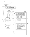
- FIG. 1 illustrates a schematic diagram of a system to assess and optimize energy usage for a facility, according to certain embodiments.
- FIG. 2 illustrates an exemplary schematic diagram of an energy management system, according to certain embodiments.
- FIG. 3 is a flow chart of an exemplary energy search engine process to assess the amount of energy used for cooling and the amount of excessive cooling affected, according to certain embodiments.
- FIG. 4 is an exemplary substantially continuous excessive cooling performance assessment, according to certain embodiments.
- FIG. 5 is a flow chart of an exemplary energy search engine process to assess energy usage, according to certain embodiments.
- FIG. 6 is a flow chart of an exemplary energy search engine process to dynamically assess energy efficiency, according to certain embodiments
- FIG. 7 is a flow chart of an exemplary energy search engine process to quantify the effectiveness of energy improving measures, according to certain embodiments.
- FIG. 8 is an exemplary substantially continuous energy performance assessment, according to certain embodiments.
- FIG. 9 is an exemplary continuous yearly key performance indicator assessment, according to certain embodiments.
- FIG. 10 is an exemplary continuous monthly key performance indicator assessment, according to certain embodiments.
- FIG. 11 is an exemplary block diagram of an energy measurement, analysis, communication, and control system, according to certain embodiments.
- Embodiments of an energy search engine use dynamic energy related data to determine how well a facility is using energy and to identify wasted energy. Further embodiments dynamically guide building system adjustments to reduce energy waste, and verify the results of such actions.
- contemporary heating, ventilation, and air conditioning (HVAC) systems use a combination of chilled coolant or chilled water, evaporative coils, forced air ducting, and hot water intermixed to provide comfort and fresh air to occupants of buildings. To provide this comfort, many building HVAC systems waste energy by simultaneously heating and cooling building air by relying on static factors and no external information to dynamically adjust the various HVAC components.
- HVAC heating, ventilation, and air conditioning
- a combination of dynamically varying factors are evaluated to dynamically adjust HVAC or other building systems for optimum occupancy comfort, lowest energy use, lowest tariff cost, and lowest GHG emissions.
- factors include, but are not limited to, natural and environmental factors, occupant factors, utility tariff factors, and GHG emission factors.
- natural and environmental factors For example, outside temperatures near a building vary hourly throughout the workday and evening. Throughout the day, the sun heats different aspects of the building which creates a variable heating component. As occupants move in and out of rooms and in and out of the building during the workday, their heat load contribution, fresh air requirements, occupant comfort requirements, and energy use via lighting, computers, and other office equipment or industrial processes in the building vary.
- the energy search engine incorporates at least one of these dynamic variables in energy modeling algorithms to provide, for example, one or more of benchmarking energy use, comparing required energy use and costs to wasted energy use and costs, dynamically guiding building system adjustments, verifying the results of such actions, and determining an optimum size of alternate electric energy systems, such as solar, wind, fuel cells, and the like to generate energy for the building.
- FIG. 1 illustrates an exemplary schematic diagram of a system 100 to dynamically assess and optimize energy usage for an energy subsystem of a facility, the facility or a network of facilities 104 .
- Facilities 104 can comprise one or more buildings, residences, factories, stores, commercial facilities, industrial facilities, data centers and the like, one or more rooms, one or more offices, one or more zoned areas in a facility, one or more floors in a building, parking structures, stadiums, theatres, and the like, one or more systems, subsystems, and/or components 104 a , a zone within the building/facility 104 , a building envelope, and the like, locally or geographically remote.
- the network of facilities 104 can comprise, for example, a geographic area, facility owner, property manager, campus, weather pattern, climate zone, facility activity type, facility total square footage, facility occupied square footage, volume of facility free space, facility schedule, facility activity levels (e.g. production quantities, number of students, etc.), utility company, applicable utility rate schedule, source of energy, type and size of local generation systems, type and size of local alternative energy systems (e.g.
- thermal solar, thermal storage, energy storage, etc. type of construction material used, type of energy systems used, model of energy systems used, facility design specifications, required air changes, measured air changes, type of energy management system installed, model of energy management system installed, performance of any existing energy management system, applicable energy codes, applicable energy regulations, applicable energy standards, applicable greenhouse gas emissions codes, applicable greenhouse gas emissions regulations, applicable greenhouse gas emissions standards, energy service company servicing the facility, energy consulting firm servicing the facility, and the like.
- Examples of the systems, subsystems and/or components 104 a include but are not limited to fans, pumps, motors, chillers, lights, heaters, heat exchangers, blowers, electric valves, air conditioning equipment, compressors, heat pumps, HVAC systems, lighting systems, motors, water heating systems, plug loads, data/Telco, variable air volume devices (VAV), gas systems, electrical systems, mechanical systems, electromechanical systems, electronic systems, chemical systems, and the like.
- VAV variable air volume devices
- the facility 104 and/or building 104 in the following discussion refer to the facility, its systems, subsystems, components, and/or a network of facilities as described above.
- Energy entering the facility 104 can be of many forms, such as, for example, thermal, mechanical, electrical, chemical, light, and the like.
- the most common forms are typically electricity or power, gas, thermal mass (hot or cold air, people), and solar irradiance.
- the electrical energy can be generated from traditional fossil fuels, or alternate forms of power generation, such as solar cells, wind turbines, fuel cells, any type of electrical energy generator, and the like.
- Ambient weather conditions such as cloudy days, or time of day, such as nighttime, may be responsible for radiant energy transfer (gains or losses).
- the facility 104 comprises measurement devices 104 b configured to measure actual energy usage in real time.
- sensors such as wired and/or wireless sensors and/or sensor systems, can measure kilowatt hours and energy spikes of electrical energy used to power the lighting system, to power the air compressor in the cooling system and to heat water for lavatories, cubic feet of gas consumed by a heating or HVAC system, amount of air flow from compressors in the cooling or HVAC system, and the like.
- the sensors can comprise current sensors, voltage sensors, EMF sensors, touch sensors, contact closures, capacitive sensors, trip sensors, mechanical switches, torque sensors, temperature sensors, air flow sensors, gas flow sensors, water flow sensors, water sensors, accelerometers, vibration sensors, GPS, wind sensors, sun sensors, pressure sensors, light sensors, tension-meters, microphones, humidity sensors, occupancy sensors, motion sensors, laser sensors, gas sensors (CO2, CO), speed sensors (rotational, angular), pulse counters, and the like.
- the facility 104 further comprises control systems, such as, for example, load shedding relays, load shifting relays, Energy Management Systems (EMS), Building Management Systems (BMS), and the like, to control energy consuming and energy saving components of the facility 104 .
- control systems such as, for example, load shedding relays, load shifting relays, Energy Management Systems (EMS), Building Management Systems (BMS), and the like, to control energy consuming and energy saving components of the facility 104 .
- EMS Energy Management Systems
- BMS Building Management Systems
- one or more controllers can raise or lower automatic blinds, shut off/reduce heating or cooling in an HVAC system in the entire or just one room of the facility 104 , switch usage of electricity from conventional generation to electricity generated by alternate forms, such as wind or solar, and the like.
- the system 100 comprises an energy search engine 102 and a user interface 108 .
- the energy search engine 102 is a cloud computing system based in a network 110 , such as the Internet 110 , as illustrated in FIG. 1 .
- the energy search engine 102 is not a cloud computing system, but receives and transmits information through the network 110 , such as the Internet 110 , a wireless local network, or any other communication network.
- the energy search engine 102 is hosted in a device located inside the facility 104 .
- the device acquires sensor data and/or smart meter data directly from existing sensors and smart meters 104 b .
- the device receives weather information, utility rate schedules, utility pricing information, grid usage information, BIM information, and other via RF broadcast signals.
- the device calculates locally the energy performance, actionable information and communicates control signals to local relays 104 c , energy systems and other systems.
- the user interface 108 allows a user to transmit information to the energy search engine 102 and receive information from the energy search engine 102 .
- the user interface 108 comprises a Web browser and/or an application to communicate with the energy search engine 102 within or through the Internet 110 .
- the user interface 108 is associated with a display and a user input device, such as a keyboard.
- the energy search engine 102 receives energy usage information from the measurement devices 104 b measuring energy usage of the systems, subsystems, and components 104 c of the facility 104 in a substantially continuous way.
- the measurement devices 104 b deliver data output that can include but is not limited to electric energy consumption data, natural or renewable gas data, air temperature data, air flow data, air quality data, building occupancy data, building zone level occupancy data, water data, environmental data, and geographic data, and the like. This data can be derived from individual circuits, critical components within the building 104 or its zones, or those systems that externally serve a building or group/network of buildings. In another embodiment, additional measurements of vibration, temperature, sound from critical motor components, and the like within buildings 104 or wherever motors are used for industrial or manufacturing processes are used to gauge the health of motor and equipment functions within the facility 104 .
- the energy search engine 102 receives in a substantially continuous way dynamic data relating to energy usage from one or more of a Building Information Modeling (BIM) 106 , a power grid 112 , a utility company 114 , building management 116 , and an environmental service 118 .
- BIM Building Information Modeling
- the BIM 106 can provide, but is not limited to specifications for the systems, subsystem, and components 104 a installed in the facility 104 , specifications for the systems, subsystem, and components with a higher energy rating that could have been installed in the facility 104 , and the like.
- the power grid 112 can provide, but is not limited to a dynamic grid response to renewable energy sources, plug-ins, projected grid demand, grid load information, energy supply capacity, and the like.
- the utility company or other sellers of energy 114 can provide, but are not limited to utility rate tariffs, real-time energy pricing, price bids, and the like.
- the building management 116 can provide, but is not limited to facility and zone level scheduling of the facility 104 , occupancy information, system status information (e.g. open doors, open windows, open shutters, etc.), and the like.
- the environmental service such as a weather service, can provide, but is not limited to dynamic weather data for the location of the facility 104 , projected weather for the location of the facility 104 , sever weather alerts, geographical factors, and the like.
- the energy search engine 102 analyzes the static data and the dynamic data received in the substantially continuous way and provides a substantially continuous energy assessment.
- the substantially continuous energy assessment include but are not limited to reports, benchmark results, energy performance assessments for the facility 104 , network of facilities 104 or any of its systems, subsystems, and components 104 a , site energy carbon footprint, source energy carbon footprint, source energy assessment, building and systems commissioning strategies, lighting strategies, data center and Telco strategies, water performance assessment, gas performance assessment, energy retrofit assessment, renewable energy assessment, and the like.
- the energy search engine 102 transmits commands to the control systems 104 c to control the systems, subsystems, and components 104 a to reduce or optimize the energy usage of the facility 104 .
- the energy search engine 102 controls the systems, subsystems, and components 104 a in a substantially continuous way.
- substantially continuous comprises within a length of time or not to exceed a length of time which occurs at regular intervals.
- data received in a substantially continuous way comprises data that is received within a definite length of time marked off by two instances.
- data received in a substantially continuous way is data that is received at regular time intervals, where the time interval does not exceed a pre-defined time interval.
- the time interval is approximately within a pre-defined time interval.
- the time interval is based at least in part on the type of information received. For example, weather can be received substantially continuously every hour, smart meter information can be received substantially continuously every 15 minutes, and grid load can be received substantially continuously every time interval which does not exceed an hour.
- providing substantially continuous energy assessment comprises providing the energy assessment within a pre-defined time interval, not to exceed a pre-defined time interval, or the like.
- controlling in a substantially continuous way to optimize energy usage comprises sending commands to the control systems 104 c or the like within a pre-defined time interval.
- the time interval is based at least in part on the specific system being controlled.
- the energy search engine may direct the facility 104 to shed or redistribute power at an interval not to exceed 5 minutes, while directing the blinds to raise or lower at an interval not to exceed 2 hours.
- substantially continuous time intervals comprise one of time intervals not to exceed 1 minute, time intervals not to exceed 5 minutes, time intervals not to exceed 15 minutes, time intervals no to exceed 1 hour, time intervals not to exceed 1 day, and time intervals not to exceed 1 week.
- FIG. 2 illustrates an exemplary block diagram of an embodiment of the energy search engine 102 .
- the energy search engine 102 comprises one or more computers or processors 202 and memory 204 .
- the memory 204 comprises modules 206 including computer-executable instructions, that when executed by the computer 202 cause the energy search engine 102 to analyze the energy data and provide the substantially continuous energy assessment metrics.
- the memory 204 further comprises data storage 208 including one or more databases to store the dynamic and or static data by the modules 206 to analyze energy usage and provide energy usage assessments.
- the computers 202 comprise, by way of example, processors, Field Programmable Gate Arrays (FPGAs), System on a Chip (SOC), program logic, or other substrate configurations representing data and instructions, which operate as described herein.
- the processors 202 can comprise controller circuitry, processor circuitry, processors, general-purpose single-chip or multi-chip microprocessors, digital signal processors, embedded microprocessors, microcontrollers and the like.
- the memory 204 can comprise one or more logical and/or physical data storage systems for storing data and applications used by the processor 202 .
- the memory 204 can further comprise an interface module, such as a Graphic User Interface (GUI), or the like, to interface with the user interface 108 .
- GUI Graphic User Interface
- the energy search engine 102 calculates a score reflecting the energy performance of the facility 104 .
- the score is a weighted average of one or more metrics that are calculated based at least in part on one or more energy variables.
- energy variables include, but are not limited to the time history of the energy (power, water, gas) consumed by the facility, the carbon equivalent of energy used at the site, the carbon equivalent of the energy generated at the source, the time history of the ambient weather conditions, the facility activity type, the facility total square footage, the facility occupied square footage, the volume of free space in the facility, the facility schedule, the facility activity levels (e.g.
- any existing local (or on site) generation systems e.g. thermal solar, thermal storage, energy storage, and the like
- any existing local alternative energy systems e.g. thermal solar, thermal storage, energy storage, and the like
- the potential for local renewable generation the potential for local alternative energy systems
- the type of construction material used the type of energy systems used, the facility design specifications, required air change, measured air changes, the type of energy management system installed, the performance of any existing energy management system, data from any existing energy, environmental and security monitoring systems, and the like.
- the facility 104 and/or building 104 and/or subsystems 104 a refer to one or more of the facility, its systems, subsystems, and components, multiple buildings comprising the facility located locally or remotely, and a network of facilities in the following discussion.
- the score or energy metrics are calculated based on historical energy data for the past week, month, quarter, year or longer time period.
- the above method can be used to backfill missing energy data for off days.
- X 1 is the average workday energy consumption for January 2011,
- X 2 is the average workday energy consumption for January 2012
- Z 1 is the average workday energy consumption for March 2011,
- Z 2 is the average workday energy consumption for March 2012
- Y 1 is the 15-minute, hourly, daily, or weekly energy consumption for workdays in February 2011, and Y 2 is the 15-minute, hourly, daily, or weekly energy consumption for the corresponding workdays in February 2012.
- the above method can be used to backfill missing energy data for off days.
- the energy generated on site (locally) is energy generated by local energy generation systems as solar PV, wind turbines, fuel cells, gas power plant, etc.
- the energy stored on site is energy that is purchased from the utility or generated locally but is stored at the time of purchase or generation for later use in energy storage systems such as batteries, compressed air, pumped water, thermal storage, etc. If the energy storage systems are discharging, then the sign of the stored energy in the equation above is negative.
- Each of the components in the equation above can be measured, calculated or estimated.
- the energy score and metrics can be proportional to the energy performance of a facility relative in a specific time period compared to its performance in a base period.
- the base period is one year.
- the metric can be proportional to the composition of source energy (solar PV, utility power, fuel cell, solar thermal, gas generator, energy storage, etc.) relative to an optimum composition of source energy for a facility, given the measured, calculated or estimated energy usage of the facility, the type of systems in the facility, the facility schedule, the facility location, the ambient weather conditions, and the like.
- source energy solar PV, utility power, fuel cell, solar thermal, gas generator, energy storage, etc.
- the metrics include but are not limited to the facility electric energy use index (kwHr/ft 2 ), the facility gas use index (therms/ft 2 ), and the facility electric demand index (kw/ft 2 ).
- the metric can be proportional to the equivalent greenhouse gas emissions of the energy used at the facility 104 , proportional to the energy generated using local renewable energy systems, proportional to the energy generated using alternative fuel systems (e.g. hydrogen fuel cells, or the like), proportional to the use of alternative energy systems, proportional to the ratio of energy used during off hours to the energy used during work hours, proportional to the ratio of energy used during work days to the energy used during off days, proportional to the minimum rate of energy consumption during a period of time (day, month, year, etc.), proportional to the simultaneous heating and cooling that may be occurring in the facility 104 , or the like.
- alternative fuel systems e.g. hydrogen fuel cells, or the like
- the metric can be proportional to the correlation between energy used for heating energy and heating requirements, proportional to the correlation between the energy used for cooling and the cooling requirements, proportional to the estimated, calculated, or measured energy used for heating divided by the amount of heating affected, proportional to the estimated, calculated or measured energy used for cooling divided by the amount of cooling affected, and the like.
- Heating requirements, cooling requirements, amount of heating affected, or the amount of cooling affected can be calculated using, but not limited to one or more of the following: ambient weather, ambient environmental conditions, desired internal temperature, ventilation rates, outside air circulation, recirculation rates, recirculated air, energy consumed by loads inside the facility 104 , heat generated by other sources inside the facility 104 , heat entering or leaving the facility 104 through mass or thermal transfer, and the like.
- the heating degree hours, a difference between ambient temperature and supply air temperature inside the facility for each hour can be used as a measure of affected heating (heating kWhr/degree heated).
- the cooling degree hours, a difference between the ambient temperature and the supply air temperature inside the facility 104 for each hour can be used as a measure of affected cooling (cooling kWhr/degree cooled).
- the required heating enthalpy hours, a difference between ambient enthalpy and a target temperature and humidity inside the facility can be used as a measure of required heating.
- the required cooling enthalpy hours, a difference between ambient enthalpy and a target temperature and humidity inside the facility can be used as a measure of required cooling.
- the affected heating enthalpy hours, a difference between ambient enthalpy and supply air enthalpy inside the facility for each hour can be used as a measure of affected heating (heating energy kWhr/kJ heated).
- the cooling enthalpy hours, a difference between the ambient enthalpy and the supply air temperature inside the facility 104 for each hour can be used as a measure of affected cooling (cooling kWhr/KJ cooled).
- FIG. 3 is a flow chart of an exemplary energy search engine process 1300 to assess the amount of energy used for cooling and the amount of excessive cooling affected.
- the amount of energy used for cooling during workdays during a year can be estimated from the profile of total energy used during the year.
- the interval energy energy consumed at regular intervals, typically 15 or 30 minutes, or any other regular interval
- the average energy and average cooling degree requirement, respectively, for each time interval during work days is calculated for each month.
- the minimum energy profile for workdays in calculated and at block 1316 , the average energy used for cooling is calculated as the difference between the energy profile and the minimum energy used during workdays.
- the minimum energy required to cool the facility by one degree is estimated for each time interval during workdays.
- the minimum energy needed for cooling during the year is calculated from the results of blocks 1322 and 1324 .
- the amount of energy used for excessive energy i.e. the amount of energy wasted due to excessive cooling is estimated.
- the energy profile for the year is calculated assuming the cooling and heating systems are at their peak efficiency all year long. The process can be repeated for time intervals during off-days.
- FIG. 4 is an exemplary substantially continuous excessive cooling performance assessment 400 .
- the performance assessment 400 is a topographical map of the facility 104 showing estimated excessive cooling energy for an average hour throughout the day in each month for a year.
- the excessive cooling is estimated by considering the load inside the building and the cooling requirement from the ambient weather, as described in FIG. 3 .
- the performance assessment 400 indicates total cooling costs being estimated at $117,000, with $75,000 in overcooling between 10 AM and 3 AM, and $19,000 in overcooling between 3 AM and 10 AM. Overcooling is estimated at $96,000, being up to 76% of the cooling costs.
- color can be used to indicate energy intensity, where brighter shades of a color indicate greater energy intensity and darker shades of the color represent lighter energy intensity (or vice versa).
- the metric can be proportional to the time history of the number of air changes, proportional to the fraction of outside air introduced to the facility, proportional to the fraction of return air recirculated, where return air is air that is exhausted from the facility using exhaust fans, proportional to the air quality inside the facility, proportional to facility peak demand and the load duration curve, which represents the time spent at each power level from the lowest demand to the peak demand, proportional to the level of compliance of the facility 104 or any of its subsystems 104 a with one or more of existing and/or future energy regulations, standards, codes, specifications and guidelines, and the like.
- the metric can be proportional to the level of energy demand reduction or load shedding initiated in response to a request from the grid or utility.
- the energy demand reduction can be calculated relative to a baseline that is adjusted for one or more of the following factors: ambient weather conditions, ambient environment conditions, changes in facility schedule, changes in facility activity, changes in facility occupancy, and the like.
- the projected energy demand reduction for the facility 104 can be calculated by estimating the amount of energy that will be used for cooling as described above and assuming that a certain percentage of the cooling energy will be reduced.
- the metric can be proportional to the change in energy consumption of the facility 104 or any of its energy subsystems 104 a compared to an energy baseline, an energy benchmark, a computed energy usage, an estimated energy usage or a projected energy usage.
- an energy baseline can be calculated for any measured or calculated metric, and correlated with ambient weather conditions, facility usage, and facility schedule.
- the calculated baseline can be used to project the value of the metric given projections of ambient weather conditions, facility usage, facility schedule, or changes in energy systems.
- the metric can be proportional to the cost of total energy used at the facility 104 , proportional to the cost of gas energy used at the facility, proportional to the cost of energy used at the facility 104 from renewable energy sources, proportional to the cost of energy used at the facility 104 from alternative energy sources, proportional to the total cost to generate the energy at the source, proportional to the cost of delivering the energy from the source to the facility 104 , proportional to the total cost of electric energy used at the facility 104 , proportional to the peak electric energy demand costs at the facility 104 , proportional to the electric energy consumption costs at the facility 104 , proportional to the avoided energy consumption costs, proportional to the avoided peak demand costs, or the like.
- the metric can be proportional to the energy consumed in the facility 104 , proportional to the total energy that can be delivered to the facility 104 , proportional to the total energy that can be generated in the facility 104 , proportional to the total energy that can be reduced in the facility 104 , proportional to the reliability of the sources of energy to the facility 104 and the total uptime of one or more of the facility's energy sources, proportional to the power quality (e.g.
- any of the metrics can be calculated every year, month, week, day, hour, or in a substantially continuous manner.
- any of the metrics can be calculated in the cloud-based server 102 and can be offered as a subscription-based service.
- FIGS. 5, 6, and 7 are flow charts of exemplary search engine processes to actively process energy consumption data, environmental data, and building use data, examples of which are described above, in a plurality of time frames, including real time, to provide one or more of the metrics related to the minimum energy required by the facility 104 and its critical subsystems 104 a for a unique geographic location, use, environment, and occupancy associated with the facility 104 , examples of which are described above.
- the energy search engine algorithms provide energy and sustainability ratings for commercial, municipal, campus, state, and federal buildings. Another embodiment provides carbon footprinting of buildings and facilities. Yet another embodiment evaluates the value of real property by evaluating its energy consumption and effectiveness and efficiency of installed systems and components. A further embodiment evaluates the instant demand response, load shedding, load shifting, and additional local generating potential of buildings, facilities, campuses and their systems. A yet further embodiment guides and evaluates actionable energy efficiency and demand response improvement measures, equipment retrofits, and commissioning strategies. In an embodiment, the technology enables compliance with legislated energy efficiency mandates and goals.
- FIG. 5 is a flow chart of an exemplary energy search engine process 500 to assess energy usage for the facility 104 .
- the facility 104 and/or building 104 and/or subsystem 104 refer to one or more of the facility, its systems, subsystems, and components, multiple buildings comprising the facility located locally or remotely, and a network of facilities in the following discussion.
- the process 500 receives substantially continuous measurements of actual energy consumption of the facility 104 .
- the process 500 receives measurements related to the actual energy consumption of the facility 104 from the measurement devices 104 b . Examples of the measurements of actual energy consumption are smart meter readings, electric meter readings, gas meter readings, current measurements, facility energy variables as described above, and the like.
- receiving substantially continuous measurements comprises receiving measurements at least every 15 minutes. In another embodiment, receiving substantially continuous measurements comprises receiving measurements at least every 5 minutes. In a further embodiment, receiving substantially continuous measurements comprises receiving measurements at least every 1 hour.
- the process 500 receives substantially continuous measurements of ambient conditions.
- the energy search engine 102 can receive weather reports including the outside air temperature, outside air humidity, cloud coverage, UV index, precipitation level, evaporative transpiration (ET) number, weather forecast, and the like.
- the status of doors, windows, and shutters associated with the facility 104 can change with time and can be received in a substantially continuous manner.
- the process 500 obtains a target energy consumption of the facility 104 based at least in part on the ambient conditions.
- Target energy consumption can be a calculated energy consumption based on baseline performance, desired environmental conditions inside the facility (temperature, humidity, air quality, etc.) projected facility schedule, projected facility usage, and projected weather conditions.
- Average facility energy consumption at a given ambient condition and facility usage level can be calculated based on historic data. This average can be set as a target for the facility when similar weather and facility usage are anticipated.
- the process 500 compares the measurement of the actual energy consumption with the target energy consumption for the facility 104 , and at block 518 , the process 500 calculates a substantially continuous energy performance assessment based at least in part on the comparison of the measurement of the actual energy consumption with the target energy consumption.
- Metrics found on the performance assessment can include but are not limited to one or more of total gas and electric current energy costs per square foot of the facility 104 , baseline electric energy rating, peak electrical energy rating, gas energy rating, efficiency of heating gas use, simultaneous heating and cooling, nighttime power index, weekend power index, EMS scheduling, full time loading, an overall performance assessment, energy wasted annually, range of estimated energy wasted annually, cost to produce energy at the source, cost to deliver energy to the facility 104 , waste as a percent of total energy used, cost of annual gas and electric energy wasted annually, electrical energy carbon footprint, gas energy carbon footprint, total energy carbon footprint, target energy usage in cost per square foot of the facility 104 , annual energy savings target, historical electricity and gas usage, historical monthly peak demand for electricity, historical energy map showing annual energy usage versus the time of the day the usage occurred, wasted heating based on a comparison of heating requirements and the actual energy used for heating, simultaneous heating and cooling based on an estimated energy used for cooling during business hours and an estimated energy used for heating during business hours, wasted cooling during business hours based on
- the metric can be proportional to the level of compliance with one or more energy standards, such as, for example, ISO 50001, LEED Silver, LEED Gold, LEED Platinum, and the like.
- the metric can be proportional to the cost of bringing the facility to compliance with one or more energy standard.
- the metric can be proportional to the energy savings (in consumption kWhr, demand kW or energy costs $) that can be realized by bringing the facility to compliance with one or more energy standard.
- the metric can be proportional to the absolute efficiency of the energy subsystem or facility 104 .
- the absolute efficiency of the energy subsystem 104 can be the ratio between the measured, calculated or estimated energy consumed by the subsystem 104 and the energy the subsystem 104 would have consumed if it operated at the theoretical limits of the subsystem 104 .
- the metric can be proportional to the achievable efficiency of the energy subsystem or facility 104 .
- the achievable efficiency of the energy subsystem 104 can be the ratio between the measured, calculated or estimated energy consumed by the subsystem 104 and the energy the subsystem 104 would have consumed if it operated at the highest efficiency achievable by such subsystems 104 .
- the metric can be proportional to the design efficiency of the energy subsystem or facility 104 .
- the design efficiency of the energy subsystem or facility 104 can be the ratio between the measured, calculated or estimated energy consumed by the subsystem 104 and the energy the subsystem 104 would have consumed if it operated per the manufacturer's design specification.
- the metric can be proportional to the savings realized (consumption kWHr, demand KW, energy costs in $) if one or more energy subsystems is operating at its theoretical, absolute, or design efficiency.
- FIG. 6 is a flow chart of an exemplary energy search engine process 400 to dynamically assess energy efficiency for the facility 104 .
- Energy search engine algorithms analyze measured energy data versus computed minimum required energy to provide, for example, energy efficiency ratings, energy consumption profiles, energy load factors, critical component assessment, and life cycle analysis of critical components.
- the process 600 obtains a minimum energy consumption for the facility 104 .
- Obtaining the minimum energy consumption at block 410 comprises obtaining the theoretical energy consumption based at least in part on models of the installed building systems, subsystems, and components 104 a at block 612 .
- obtaining the minimum energy consumption comprises obtaining a theoretical energy consumption based at least in part on ideal models or the theoretical limits of the installed building systems, subsystems, and components 104 a.
- Obtaining the minimum energy consumption at block 610 further comprises obtaining an achievable minimum energy consumption based at least in part on specifications for high energy efficiency equivalents of the installed building systems, subsystems, and components 104 a at block 614 and obtaining a designed minimum energy consumption based at least in part on specifications and cumulative loads for the installed building systems, subsystems, and components 104 a at block 616 .
- the process 600 receives substantially continuous measurements of the facility energy consumption.
- the measurements are provided by the measurement devices 104 b .
- measurements are calculated.
- the measurements are estimated.
- the process 600 compares the minimum energy consumption to the measurement of the facility energy consumption in a substantially continuous way. Comparing at block 630 comprises comparing the theoretical minimum energy consumption to the measurement of the facility energy consumption at block 632 , comparing the achievable minimum energy consumption to the measurement of the facility energy consumption at block 634 , and comparing the designed minimum energy consumption to the measurement of the facility energy consumption at block 636 .
- the process 600 calculates a substantially continuous energy performance assessment for the facility 104 .
- Calculating the substantially continuous energy performance at block 640 comprises determining a theoretical energy efficiency at block 642 , determining an achievable energy efficiency at block 644 , and determining a designed energy efficiency at block 646 .
- the absolute or theoretical efficiency metric for a fan can be calculated from a measurement, estimation or calculation of one or all of the following: fan upstream pressure, fan downstream pressure, flow temperature, fan speed, mass flow rate through the fan, volumetric flow rate through the fan, and/or energy consumed by the fan.
- the fan's absolute efficiency is then calculated by dividing the energy consumed by the energy that should have been consumed by the fan if it operated at its theoretical efficiency under the same conditions of upstream pressure, downstream pressure, fan speed, flow temperature, volumetric flow rate, or mass flow rate through the fan.
- the achievable efficiency metric for a fan can be calculated from a measurement, estimation or calculation of one or all of the following: fan upstream pressure, fan downstream pressure, flow temperature, fan speed, mass flow rate through the fan, volumetric flow rate through the fan, and/or energy consumed by the fan.
- the fan's achievable efficiency is then calculated by dividing the energy consumed by the energy that should have been consumed by the highest performing fan available operating under the same conditions of upstream pressure, downstream pressure, fan speed, flow temperature, volumetric flow rate, or mass flow rate through the fan.
- the design efficiency metric for a fan can be calculated from a measurement, estimation or calculation of one or all of the following: fan upstream pressure, fan downstream pressure, flow temperature, fan speed, mass flow rate through the fan, volumetric flow rate through the fan, and/or energy consumed by the fan.
- the fan's design efficiency is then calculated by dividing the energy consumed by the energy that should have been consumed by the fan operating per the manufacturer's design specifications under the same conditions of upstream pressure, downstream pressure, fan speed, flow temperature, volumetric flow rate, or mass flow rate through the fan.
- the theoretical efficiency of a facility envelope on hot days can be calculated assuming a perfectly insulated facility envelope that blocks all radiant heat transfer into the facility 104 , all convective heat transfer into the facility 104 , and all infiltration of mass in and out of the facility 104 .
- the heat generated in the facility 104 is calculated from a measurement, estimate, or calculation of the energy consumed in the facility 104 , such as indoor lighting, plug load, heating gas, etc., and the heat generated by occupants and processes in the facility 104 .
- the heat removed from the facility 104 can be calculated from a measurement, estimate, or calculation of the difference between enthalpy of the ventilation and cooling air leaving the envelope and the enthalpy of the ventilation and cooling air entering the envelope.
- the facility 104 can be assumed to be at constant operating temperature. For a perfectly insulated envelope at a constant internal temperature, the heat removed from the facility 104 is equal to the heat generated in the facility 104 .
- the envelope efficiency on a hot day can be calculated as the ratio of the heat generated in the facility 104 divided by the heat removed from the facility 104 .
- the design efficiency of a roof top packaged HVAC unit can be calculated by measuring the enthalpy (temperature, humidity and flow rate) of the air entering the HVAC system (fraction of return air+fraction of outside air), the enthalpy of the air leaving the HVAC system (supplied to the facility 104 ) and the energy consumed by the HVAC system.
- the energy consumed by the HVAC is divided by the enthalpy of air entering the HVAC—enthalpy of air leaving the HVAC] to yield a measured coefficient of performance (COP).
- the measured COP is then divided by the design COP specified by the HVAC manufacturer at the given HVAC load and the resulting ratio comprises the design efficiency of the HVAC system.
- FIG. 7 is a flow chart of an exemplary energy search engine process 500 for demand side analysis.
- the energy search engine 102 matches varying demand side load requirements to supply side generating and grid capability to establish relative value energy pricing.
- the exemplary process 700 quantifies the effectiveness of energy improving measures, such as rating the energy efficiency and carbon footprint of the facility 104 and/or any or all of its systems 104 a (individually or collectively) to determine opportunities to introduce energy efficiency, install retrofits, commission facilities for monitoring based commissioning (MBCx), retrocommissioning (RCx), continuous commissioning, and the like, and provide peak reduction and demand response strategies and actions.
- energy improving measures such as rating the energy efficiency and carbon footprint of the facility 104 and/or any or all of its systems 104 a (individually or collectively) to determine opportunities to introduce energy efficiency, install retrofits, commission facilities for monitoring based commissioning (MBCx), retrocommissioning (RCx), continuous commissioning, and the like, and provide peak reduction and demand response strategies and actions.
- the process 700 obtains an energy usage benchmark for the facility 104 .
- the energy usage benchmark is an energy usage point of reference across a network of facilities that share something in common against which the energy usage of the facility 104 may be compared.
- the benchmark could be one of an Energy Star® rating, historical energy use of the facility 104 , energy performance of buildings in a specific geographic area, energy performance of buildings of a certain size, energy performance of buildings of a certain activity, energy performance of buildings with a certain type of cooling technology, energy performance of buildings with a certain type of heating technology, energy performance of buildings with a certain type of construction material, energy performance of buildings with a certain brand and model of EMS, energy performance of buildings with a certain energy certification, energy performance of buildings with a certain energy rating, energy performance of buildings with a certain local energy source (e.g. solar PV), or the like.
- Energy Star® rating historical energy use of the facility 104
- energy performance of buildings in a specific geographic area energy performance of buildings of a certain size, energy performance of buildings of a certain activity, energy performance of buildings with a certain type of cooling technology, energy performance of buildings with a certain type of heating technology, energy performance of buildings with a certain type of construction material, energy performance of buildings with a certain brand and model of EMS, energy performance
- the process 700 receives substantially continuous measurements of actual energy consumption for the facility 104 before installation of energy improvement measures.
- the measurements are obtained from the measurement devices 104 b.
- the process 700 establishes a first baseline of energy usage for the facility 104 based at least in part on the measurements of actual energy consumption received before the installation of the energy improvement measures.
- establishing the baseline before installation comprises obtaining an expected energy usage for the facility which has installed systems, subsystems, and components 104 c , and a load profile.
- the baseline is established by recording the energy performance of the facility over a period of time, e.g. 3 months or 1 year. Multiple baselines can be calculated, such as for night hours on work days, morning hours on work days, afternoon hours on work days, night hours on off days, morning hours on off days, afternoon hours on off days.
- baselines can be calculated, including, but not limited to total energy consumption (kWhr), electrical energy consumption (kWhr), electrical demand (kW), gas consumption (therms), energy used for lighting (kWhr), demand due to lighting (kW), energy used for cooling (kWhr), demand due to cooling (kW), and the like.
- Baselines can also be normalized with ambient weather conditions, cooling degree hours, heating degree hours, facility usage levels, facility occupancy, etc.
- the baseline of energy consumed (kWhr) during morning hours on work days could be the average consumption during morning hours for all workdays of a certain segment or entire segment of the baseline calculation period.
- the consumption baseline can be normalized to cooling degree hours by dividing the average consumption for each of the morning hours on work days with the average cooling degree hour for each of those hours.
- the process 700 compares the benchmark with the baseline established before the installation of the at least one energy improvement measure.
- the process 700 receives substantially continuous measurements of actual energy consumption for the facility 104 after installation of at least one energy improvement measure.
- the measurements are obtained from the measurement devices 104 b.
- Examples of energy improvement measures are, but not limited to, installing a renewable energy system, retrofitting equipment, commissioning, load shifting, load shedding, installing energy storage, installing LED lighting systems, installing variable frequency drive (VFD) systems, installing new windows, installing new wall insulation, replacing inefficient boilers, upgrading the insulation of hot and cold water pipes, installing economizer systems, installing evaporative cooling systems, adding circulation fans, changing the location of supply and return ventilation air ducts, installing pool covers, installing thermal storage systems, installing shades and awnings, and the like.
- VFD variable frequency drive
- the process 700 establishes a second baseline based at least in part on the measurements of actual energy consumption received after the installation of the energy improvement measures.
- establishing the baseline after installation comprises obtaining an energy usage for the facility which has installed systems, subsystems, and components 104 c , and a load profile.
- the process 700 compares the first baseline established before installation of the at least one energy improvement measure with the baseline established after installation of the at least one energy improvement measure.
- the process 500 compares the benchmark with the baseline established after installation of the at least one energy improvement measure.
- the process 700 quantifies the effectiveness of the at least one energy improvement measure.
- the process 700 determines the impact of the at least one energy improvement measure against the first baseline of energy usage for the facility 104 .
- the process 700 determines the impact of the at least one energy improvement measure against the benchmark for the facility 104 .
- quantifying the effectiveness of the at least one energy improvement comprises determining one or more of a payback calculation, a payment of an incentive, a valuation of real property for purposes that include projecting the value of operational strategies and behaviors or equipment replacements that result in altered real property valuations, a carbon offset used in carbon trading, and the like.
- FIG. 8 is an exemplary substantially continuous energy performance assessment 800 .
- the assessment 800 includes information about the current energy usage of the facility 104 , rating of energy metrics, and targeted energy usage.
- the metrics for current energy usage include the total gas and electric energy cost per square foot of the facility 104 ; low and high ranges for the annual estimated energy wasted, the percent of wasted energy out of the total energy used, the cost of the annual energy wasted; and carbon footprint metrics, such as the carbon footprint of the electrical energy used, the carbon footprint of the gas energy used, and total carbon footprint for the facility 104 .
- Energy metrics such as the baseline energy rating, the peak electrical energy rating, the gas energy rating, the efficiency of the gas used for heating, the occurrence of simultaneous heating and cooling, the nighttime power index, the weekend power index, the energy management system scheduling, and the full time loading levels, are rated on a poor, average or good scale.
- the assessment 600 includes a comparison of energy usage, energy savings, and carbon reductions for the current energy implementation of the facility with at least two suggested energy reduction implementations to provide a better target and a best target.
- the energy search engine 102 provides the energy performance of a network of facilities 104 on a multi-dimensional map.
- the multi-dimensional map plots one or more metrics on a geographical map with colors, coordinates and shapes. For example, a metric proportional to the fraction of a facility's energy demand that can be shed (reduced) at any given time can be plotted on a geographical map of the area. Every facility 104 can be indicated by a circle, with the size of the circle proportional to the levels of demand (in kW) that can be shed at each facility 104 and the color of the circle indicating the percent facility demand that can be shed. Similar maps can be used to animate the effect of a cloud passing on the potential for demand reduction across a network of facilities 104 based on demand projections calculated using the energy search engine 102 .
- FIG. 9 is an exemplary continuous yearly key performance indicator chart 900 and FIG. 10 is an exemplary continuous monthly key performance indicator chart 1000 .
- Both charts 900 and 1000 track key performance indicators, including but not limited to baseline electric use index, peak electrical energy use index, gas energy use index, heating gas efficiency consistency, simultaneous heating and cooling, nighttime power index, weekend power index, EMS scheduling, and full-time loading, as described above.
- Chart 900 indicates the year to date energy performance
- chart 1000 indicates the energy performance for a month.
- the indicator bars are in color to represent score quality/level where red indicates a poor score, green indicates a good score, and yellow indicates a mediocre score that could be improved.
- one or more alerts are associated with one or more of the metrics. Exceeding, or dropping below a specified metric value and for a specified amount of time will signal an alert and cause an action to be taken.
- the action may include the closure of relays, a command to be sent via wired or wireless Ethernet®, RF module, machine interface, wired connection, or the like.
- the action may also include a message to be sent to a computer desktop, a mobile device, a mobile application, a Facebook® page, a Twitter® account, a message board, a broadcast system, or the like.
- one or more alerts are associated with one or more of the metrics.
- the alerts can be initiated when a metric exceeds or drops below a certain value for a specified amount of time if one or more other metrics, measured variables, such as, for example, temperature, pressure, humidity, flow, current, or the like, estimated variables, calculated variables, and/or any mathematical combination of the metrics and/or variables are at, above, or below a specific value for a specified amount of time, where the specific value can be a function of one or more metrics, measured variables, estimated variables, calculated variables, any mathematical combination of the variables, and/or any mathematical combination of the metrics.
- the energy search engine 102 can report a daily maintenance task list, where the energy search engine 102 generates a list of required maintenance tasks sorted by criticality, energy performance impact, cost performance impact, impact on carbon footprint, cost to fix, and the like. Further, an embodiment of the energy search engine 102 can report equipment diagnostics such that the energy search engine will continuously diagnose and rate the performance of each of the building's equipment 104 a.
- Further embodiments of the energy search engine 102 determines and reports on when and where a building or its energy consuming or energy generating subsystems are operating properly or are in need of maintenance, tuning, load shifting, load shedding, or equipment replacement based at least in part on data level flags that correspond with incremental level changes in energy consumed or generated.
- the energy search engine 102 uses day ahead projected hourly weather data and projected facility schedule and usage to predict energy performance (e.g. kWhr consumption, kW demand, efficiency metrics, etc.) based on a calculated baseline for the facility 104 , and correlations of energy baseline with ambient weather, facility schedule and facility usage.
- energy performance e.g. kWhr consumption, kW demand, efficiency metrics, etc.
- the energy search engine 102 uses day ahead projected hourly weather data, projected facility schedule, projected facility usage, utility rate information, day ahead utility pricing information, day ahead grid information, day ahead energy cost information, to predict energy cost (kW demand cost, kWhr consumption cost, gas therm cost, water gallons cost, etc.) based on a calculated baseline for the facility 104 , and correlations of energy baseline with ambient weather, facility schedule and facility usage.
- the energy search engine 102 provides data output that are useful to benchmark and evaluate real property energy consumption and carbon emissions/footprint for purposes that include projecting the value of operational strategies and behaviors or equipment replacements that result in altered real property valuations, and the like.
- the energy search engine 102 provides data output that are useful for auditing compliance with existing and emerging legislation on energy use, carbon emissions, and for achieving energy reduction and carbon emission reduction goals at facilities.
- FIG. 11 illustrates an embodiment of the energy measurement, analysis, communication, and control system.
- the system comprises Digital Energy Measurement Modules 301 , 301 B, 301 Phase; Current/power/voltage Measurement Modules 301 C for energy calculation or energy data processing; and Modules 303 , 304 , 305 for enabling energy data quantity reduction and data error correction without compromising the value of the measured data.
- the energy data quantity reduction is based, at least in part, on application of an embodiment of the data reduction/data compression technique illustrated in FIG. 4 and filtering parameters, such as change in measured energy (+ ⁇ x %), rate of change of measured energy (t), and the like.
- Data Analysis Module 304 comprises ports where analog I/O analog sensor input and output control signals are exchanged with external sensors, and devices and digital I/O modules where external digital sensor input and control information are exchanged with outside sensors and devices.
- Module 306 provides compensated inputs for on-board and/or remote temperature sensors.
- Module 306 A provides inputs from other on-board and/or remote sensors such as pressure sensors, light sensors, acceleration sensors, tension-meters, flow sensors, gas sensors, microphones, and others.
- Module 307 provides PWM controller outputs Class D or Class E PWM control signals for the efficient control of external electric loads through direct connection with high speed electronic switches such as Triac's, MosFets, or IGFET's.
- Module 308 enables optional digital data encryption.
- Module 309 is used for digital data storage.
- Module 311 provides communications and control commands.
- Module 310 provides global positioning or location sensing (GPS).
- Module 312 is a web server and Module 313 provides a human machine interface that can be an LCD display and keypad or keyboard, or the like.
- Modules 301 , 301 B, 301 Phase, 301 C, and 302 perform digital energy measurement and calculations in electric circuits that are located in any residence, building, commercial or industrial facility, in electric circuits that are used for powering electric powered transportation systems and/or charging electric vehicles, and energy that is provided or delivered by any and all electric generating power systems including solar, wind, fuel cell, micro turbines, or other types of electric generating devices and systems.
- Measurement devices 302 are associated with an electrical circuit and acquire an analog measurement of the current, voltage or power in the associated electrical circuit.
- Measurement devices 302 can be, for example, current transformers (CT) or the like.
- CT current transformers
- a current transformer 302 produces a reduced current accurately proportional to the current in the circuit, which can be conveniently connected to measuring and recording instruments.
- the current transformer 302 also isolates the measuring instruments from what may be very high voltage in the monitored circuit.
- Modules 301 B comprise a latching double pole double throw gate and permit the automatic correction for the polarity of the measured current, should the current transformer 302 be incorrectly installed.
- the position of latching DPDT gate in Module 301 B is determined by algorithms that operate on Modules 305 and 306 to evaluate when the voltage phase from Phase ADC Module 301 and the current phase from Module 301 of a given measurement circuit are separated by more than approximately 90 degrees and less than approximately 270 degrees. When this condition exists, the CT 302 polarity is deemed incorrect and the position of latching DPDT gate is switched to the alternate position.
- measurement devices 302 are Rogowski coils, DC shunts, external digital current sensors, and external analog current sensors.
- the system provides for the intermixed use of clamp on current measuring toroid transformers (CTs), Rogowski coils, DC shunts, or other current measuring devices.
- CTs clamp on current measuring toroid transformers
- Rogowski coils Rogowski coils
- DC shunts or other current measuring devices.
- ADC Modules 301 convert the analog measurement from the measurement devices 302 into a digital measurement for use in the system.
- ADC Modules 301 comprise an analog to digital converter, and at least one jumper.
- the analog to digital converter is an Analog Devices IC, part number ADC 5169, or the like.
- the jumper configuration of the ADC Module 301 is field selectable for the accurate measurement of 1 to n electric circuit phase configurations including single phase, split phase, three phase Delta, and three phase Wye. Phase configuration and association of the ADC module with its respective voltage phase can also be done in software in another embodiment.
- Phase ADC Module 301 couples to energized circuits with phase A, B, and/or C through resistive voltage dividers to digitally measure voltage amplitude and phase information.
- the digital measurement information collected by the Phase ADC Module 301 and the ADC Modules 301 for 1 to n measured electrical circuits is sent to the Energy Calculation Module 301 C.
- the data sample rate ranges between approximately 10 samples/second to approximately 24 kilo samples/second.
- Data reduction processes comprises Modules 303 , 304 , and 305 utilizing an embodiment of the data reduction/data compression technique illustrated in FIG. 4 to substantially reduce the quantity of measured energy data that will be reported in real time, stored in memory data, or “pushed” to remote or cloud data base or “pulled” from a user inquiry.
- the reduced quantity of energy data is based on previously defined or user defined data filtering parameters such as amount of change or rate of change of measured or calculated energy data.
- the energy or environmental data quantity reduction technique that is shown in embodiments is broadly applicable to any energy or environmental device or network of devices.
- Module 303 samples the measured and calculated energy data from 1 to n ADCs at frequencies up to approximately 24,000 samples per second and sends the data to the Data Validation and Correction Module 305 for determination of data accuracy.
- Module 304 analyses the energy data and also receives input from other internal and external sensors, Modules 306 and 306 A.
- the Analysis Module 304 also contains algorithm for reducing the number of points passed from Module 305 and sends the formatted and substantially reduced quantity of measurement data to at least Modules 311 , 312 , 313 and 309 . Based on comparison of this measured energy data and input from external environmental sensors, a control signal is sent to external devices for load control through the Analog I/O, Digital I/O, or PWM Controller Module 307 .
- Data Validation and Correction Module 305 and Data Analysis Module 304 for 1-n electric circuits provide real time digital analysis, validation, and auto correction of measured energy use and the quality of energy that is available at a power generating system that is found on the grid, smart grid, micro grid, residence, building, commercial facility, or for electric vehicle and electric powered transportation systems, according to certain embodiments.
- Embodiments include electrical circuits powered by solar, wind, fuel cells, and any type of electric energy generator.
- Module 305 generates signals to control the Data Analysis Module 304 when the voltage phase and the current phase of a given ADC Module 301 exhibits more than approximately 90 degrees and less than approximately 270 degrees of phase differential.
- Software used by the Data Analysis Module 305 automatically identifies the correct phase that is associated with ADC Module 301 and attaches this phase information to the correct energy information from ADC Module 301 in the Data Validation and Error Correction Module 305 .
- Module 306 does not configure the ADC Module 301 . Instead the output data from a specific ADC Module 301 is correctly attached to the correct phase data (A, B, C, . . . , n) from Phase ADC Module 301 in Module 305 .
- Data Validation and Correction Module 305 analyzes energy spikes to determine whether the spike is valid or is noise or corrupted data by acquiring additional samples at approximately the same time as the energy spike from Module 303 which provides a data gateway. If the energy spike is a valid data measurement, the amplitude of the later acquired sample will be proportional to the energy spike. If the amplitude of the later acquired data is substantially different than the energy spike, Module 305 determines that the energy spike was caused by noise, and treats the bad data as irrelevant and not worthy of being passed on for storage or “push” or “pull” communication.
- Data Analysis Module 304 processes measured energy data and compares it with external environmental and facility use information to derive and deliver electric load, device, and BMS/EMS control signals that are used to reduce or increase the electric energy in a specific circuit.
- Data Error Correction Module 305 processes measured energy data and compares it with prior data samples to insure that only relevant and accurate data is passed from Data Gateway Module 303 to the Communication Module 311 or to I/Os or to PWM Controller Module 307 .
- Data Encryption Module 308 optionally encrypts the data that is derived from the measuring of all electric circuits and the location of circuits and measurement apparatus using secure and anti-hacking data encryption algorithms. Module 308 can also be positioned just downstream of Module 304 . In one embodiment, the Data Encryption Module 308 uses anti tamper and anti hacking handshaking through the use of existing and emerging “smart grid” security data protocols.
- Data Storage Memory Module 309 stores the measured and digitized electric circuit data and measured electric energy quality data.
- the Data Storage Memory Module 309 provides a data buffer in case communication channel with the local or remote host is broken. The buffer decouples data sampling rates and data reporting rates. The data is stored locally at the required sampling rate until the communication lines are re-established. The data is then transferred to the host ensuring no data loss during communication breakdown.
- Module 311 provides the system with a unique address.
- Module 311 can push data to and/or pull data from 3rd party hardware or software including but not limited to structured query language (SQL) and/or SAP databases, Cloud based databases, and/or any type of computing device.
- SQL structured query language
- SAP databases Cloud based databases
- Data Command and Communication Module 311 pushes digitally measured electric circuit energy use data from 1-n circuits using protocols, such as, for example, Ethernet, ZigBee, PLC (Power Line Carrier), WiFi, WiMax, GSM to a remote device for real time analysis, for real time analysis and control, and/or to a remote structured query language (SQL), SAP, or cloud data base for storage, comparison of data, data mining, and data analysis for a multiplicity of purposes including billing and control of circuit circuits, smart appliances, electric vehicle and electric transportation systems.
- the data can be delivered in XML, JSON, CSV, ASCII Strings, Binary Strings, and other formats.
- the Data Command and Communication Module 311 uses data clock synchronization and system clocking via Ethernet connection.
- Other system connections include networked TCP/IP, client-server ModBus, BacNet, mesh network ZigBee wireless, WiFi, and WiMax that are operating either individually or concurrently to interact with 3rd party hardware and software.
- the Data Command and Communication Module 311 can simultaneously retain a copy of the measured data in onboard memory so that it can be viewed and accessed through the web server, according to certain embodiments.
- the Data Command and Communication Module 311 can also act as a slave to the acquisition host, such as a PC or the like, and communicate with the master host in one of several standard protocols, such as Ethernet protocols including ModBus and BacNet, for example.
- the Module 311 then acts as a translation of the protocol to serial communication.
- the software Digital I/O module and Analog I/O module interfaces with the Data and Command Communication Module 311 and with the Data Analysis Module 304 to enable two-way software commands and interrupts to be exchanged between the Data Analysis Module 304 and other BMS, BEMS, electrical vehicle charge stations, motor control systems, electrical control systems, smart appliances, programmable logic controllers, and the like.
- the Temperature Sensor Compensation Module 306 comprises calibration compensation look up tables to correctly utilize J or K thermocouple devices or wired or wireless thermostats for external local or remote measurement of temperature.
- the PWM Controller Module 307 is directed either by the Data Analysis Module 306 or the Communication and Command Module 311 to output a signal that consists of variable duty cycle pulses for load control through external high speed electronic switches such as high power MOSFETS, IGFETs, or other high speed electronic switching devices.
- variable width pulses enable an external high speed electronic switch to control the electric energy and carbon footprint of any electric circuit or device including lighting circuits, motor circuits, air handling systems, HVAC compressor systems, and the like.
- This embodiment when combined with an external high speed electronic switch refers to a Class D or Class E control system design.
- the GPS Location Information Module 310 interfaces with the Data and Command Communication Module 311 and maps the location of each identified circuit board that has a unique MAC address.
- Analog/digital input/output I/O modules interface external sensors with the Data Analysis Module 304 and the Data Command and Communication Module 311 .
- Sensors such as, for example, temperature sensors, humidity sensors, light sensors, occupancy sensors, motion sensors, acceleration sensors, vibration sensors, flow sensors, wind speed, heat sensors, gas sensors, gas spectrometers, laser sensors, humidity sensors, and other environmental sensors such as water flow, air flow, and gas flow provide data, including environmental, fuel type, or other data, to the Module 304 or 311 where the data is analyzed to calculate energy loads, determine possible energy reduction, identify malfunctioning systems, and/or the like.
- Data Command and Communication Module 311 implements predetermined and automated power reduction steps in energy use systems, smart appliances, or plug loads, based at least in part on the sensor data or on external demand response commands, according to certain embodiments.
- the analog/digital I/O module interfaces with analog sensor input or digital input, analog or digital control circuit input, and output circuits for localized or remote control of relays, switches, programmable logic controllers, Building Management Systems (BMS), Building Energy Management Systems (BEMS), energy management and carbon footprint reporting systems, or the like.
- the analog/digital I/O module interfaces with pulse counters from natural gas or water meters to integrate this additional data.
- Web server 312 and Human Machine Interface (HMI) 313 provide the user with a Web-based user interface to the system of FIG. 11 .
- HMI 313 are 8, 16, or more segment LEDs or LCD panels, Keypads, Qwerty keyboards, and the like.
- Embodiments provide user interface software that is accessible via Ethernet from personal computers (PCs) on the local area or wide area network.
- the user interface allows the user to define the grouping of circuits to be measured and the locations for the circuits to be measured.
- the system provides users with “drag and drop” functionality of circuits between groups and locations and “drag and drop” functionality for charting and reporting in a mobile app. Users can also, in one embodiment, view real time or stored and “pushed” or “pulled” energy use on Mobile platforms, such as for example, I-Phone, Android, BlackBerry, and the like.
- the user can define minimum and maximum alert thresholds on all measured and calculated metrics, such as, voltage, current, energies, energy consumption rate, powers, power factor, cost, cost rate, energy efficiency metric, energy efficiency rating, and the like, for each circuit, group of circuits and location.
- Comparative alert thresholds are used on metrics and for circuits where alerts are triggered by relative energy signature of circuits, groups and locations with each other or with established baselines or benchmarks.
- Predictive alert thresholds are used on metrics and for circuits where alerts are triggered by projected energy consumption of a circuit, group or location.
- the system provides the user with an alert through email, text message, Facebook, Twitter, voicemail, RSS feeds, multi-media message automatic alerts, and the like.
- the alert is accompanied by a description of the trigger event including charts and reports on history before alert trigger and projected consumption and results.
- the Web Server 312 or the push capability the user is provided with animated and interactive desktop and mobile widgets for communicating energy consumption levels, energy ratings and critical energy conservation measures to end users.
- the system communicates energy consumption levels, energy ratings and critical energy conservation measures to end users through RSS feeds with desktop tickers.
- the electrical signature comprises at least one of a current and/or voltage waveform, current and/or voltage levels and peaks, power factor, other sensor information, such as temperature, vibration, acceleration, rotation, speed, and the like, of any “downstream” motor or pump.
- An embodiment of the algorithm for Energy Data Reduction relates to bandwidth issues that will be encountered on the ‘smart grid” just as MPEG did for audio and video. With a plethora of measurement and reporting systems running at high speed, data collection will overload a network with data. Use of this technique or method on any chip, device, circuit or computer will reduce the communication bandwidth and processing requirements of said devices.
- the energy search engine 102 provides preplanned or instant actionable energy optimization strategies through activation of systems and circuits that shed and/or shift energy consumption and/or provide supplemental energy resources.
- the energy search engine 102 can provide data output to Energy Management Systems (EMS) and/or Building Management Systems (BMS) and/or load control relays to respond with either instant or preprogrammed load shedding strategies, load shifting strategies, and supplemental energy supply strategies, according to certain embodiments.
- EMS Energy Management Systems
- BMS Building Management Systems
- acts, events, or functions of any of the algorithms described herein can be performed in a different sequence, can be added, merged, or left out all together (e.g., not all described acts or events are necessary for the practice of the algorithm).
- acts or events can be performed concurrently, e.g., through multi-threaded processing, interrupt processing, or multiple processors or processor cores or on other parallel architectures, rather than sequentially.
- a machine such as a general purpose processor, a digital signal processor (DSP), an ASIC, a FPGA or other programmable logic device, discrete gate or transistor logic, discrete hardware components, or any combination thereof designed to perform the functions described herein.
- DSP digital signal processor
- a general purpose processor can be a microprocessor, but in the alternative, the processor can be a controller, microcontroller, or state machine, combinations of the same, or the like.
- a processor can also be implemented as a combination of computing devices, e.g., a combination of a DSP and a microprocessor, a plurality of microprocessors, one or more microprocessors in conjunction with a DSP core, or any other such configuration.
- a software module can reside in RAM memory, flash memory, ROM memory, EPROM memory, EEPROM memory, registers, hard disk, a removable disk, a CD-ROM, or any other form of computer-readable storage medium known in the art.
- An exemplary storage medium can be coupled to the processor such that the processor can read information from, and write information to, the storage medium. In the alternative, the storage medium can be integral to the processor.
- the processor and the storage medium can reside in an ASIC.
- the words “comprise,” “comprising,” and the like are to be construed in an inclusive sense, as opposed to an exclusive or exhaustive sense; that is to say, in the sense of “including, but not limited to.”
- the words “proportional to”, as generally used herein, refer to being based at least in part on.
- the words “coupled” or connected”, as generally used herein, refer to two or more elements that may be either directly connected, or connected by way of one or more intermediate elements. Additionally, the words “herein,” “above,” “below,” and words of similar import, when used in this application, shall refer to this application as a whole and not to any particular portions of this application.
- words in the above Detailed Description using the singular or plural number may also include the plural or singular number respectively.
- conditional language used herein such as, among others, “can,” “could,” “might,” “may,” “e.g.,” “for example,” “such as” and the like, unless specifically stated otherwise, or otherwise understood within the context as used, is generally intended to convey that certain embodiments include, while other embodiments do not include, certain features, elements and/or states.
- conditional language is not generally intended to imply that features, elements and/or states are in any way required for one or more embodiments or that one or more embodiments necessarily include logic for deciding, with or without author input or prompting, whether these features, elements and/or states are included or are to be performed in any particular embodiment.
Landscapes
- Engineering & Computer Science (AREA)
- Business, Economics & Management (AREA)
- Human Resources & Organizations (AREA)
- Power Engineering (AREA)
- Physics & Mathematics (AREA)
- General Physics & Mathematics (AREA)
- Economics (AREA)
- Strategic Management (AREA)
- Marketing (AREA)
- Theoretical Computer Science (AREA)
- General Business, Economics & Management (AREA)
- Health & Medical Sciences (AREA)
- Tourism & Hospitality (AREA)
- Entrepreneurship & Innovation (AREA)
- Accounting & Taxation (AREA)
- Finance (AREA)
- Development Economics (AREA)
- Automation & Control Theory (AREA)
- Primary Health Care (AREA)
- Public Health (AREA)
- Water Supply & Treatment (AREA)
- General Health & Medical Sciences (AREA)
- Operations Research (AREA)
- Quality & Reliability (AREA)
- Game Theory and Decision Science (AREA)
- Educational Administration (AREA)
- Electromagnetism (AREA)
- Radar, Positioning & Navigation (AREA)
- General Engineering & Computer Science (AREA)
- Management, Administration, Business Operations System, And Electronic Commerce (AREA)
- Computer Networks & Wireless Communication (AREA)
- Testing Of Devices, Machine Parts, Or Other Structures Thereof (AREA)
Priority Applications (10)
| Application Number | Priority Date | Filing Date | Title |
|---|---|---|---|
| US13/685,478 US9727068B2 (en) | 2011-11-28 | 2012-11-26 | Energy search engine with autonomous control |
| US14/248,176 US20140222486A1 (en) | 2011-11-28 | 2014-04-08 | Energy search engine methods and systems |
| US14/248,209 US20140222232A1 (en) | 2011-11-28 | 2014-04-08 | Energy search engine methods and systems |
| US14/248,174 US20140222665A1 (en) | 2011-11-28 | 2014-04-08 | Energy search engine methods and systems |
| US14/248,195 US20140222231A1 (en) | 2011-11-28 | 2014-04-08 | Energy search engine methods and systems |
| US14/470,790 US20140371935A1 (en) | 2011-11-28 | 2014-08-27 | System and methods to assess, manage and control distributed renewable energy resources on a grid or microgrid and achieve a 100% renewable energy grid or microgrid from clean, carbon free, and water conserving distributed renewable energy technologies and resources |
| US14/470,811 US20140371936A1 (en) | 2011-11-28 | 2014-08-27 | System and methods to aggregate instant and forecasted excess renewable energy |
| US15/918,170 US10545525B2 (en) | 2011-11-28 | 2018-03-12 | Self-driving building energy engine |
| US16/773,117 US11275396B2 (en) | 2011-11-28 | 2020-01-27 | Method and apparatus to assess and control energy efficiency of fan installed in facility of building systems |
| US17/654,661 US11860661B2 (en) | 2011-11-28 | 2022-03-14 | Method and apparatus to assess and control energy efficiency of pump installed in facility of building systems |
Applications Claiming Priority (2)
| Application Number | Priority Date | Filing Date | Title |
|---|---|---|---|
| US201161564219P | 2011-11-28 | 2011-11-28 | |
| US13/685,478 US9727068B2 (en) | 2011-11-28 | 2012-11-26 | Energy search engine with autonomous control |
Related Child Applications (6)
| Application Number | Title | Priority Date | Filing Date |
|---|---|---|---|
| US14/248,195 Continuation US20140222231A1 (en) | 2011-11-28 | 2014-04-08 | Energy search engine methods and systems |
| US14/248,209 Continuation US20140222232A1 (en) | 2011-11-28 | 2014-04-08 | Energy search engine methods and systems |
| US14/248,174 Continuation US20140222665A1 (en) | 2011-11-28 | 2014-04-08 | Energy search engine methods and systems |
| US14/248,176 Continuation US20140222486A1 (en) | 2011-11-28 | 2014-04-08 | Energy search engine methods and systems |
| US14/470,811 Continuation US20140371936A1 (en) | 2011-11-28 | 2014-08-27 | System and methods to aggregate instant and forecasted excess renewable energy |
| US14/470,790 Continuation US20140371935A1 (en) | 2011-11-28 | 2014-08-27 | System and methods to assess, manage and control distributed renewable energy resources on a grid or microgrid and achieve a 100% renewable energy grid or microgrid from clean, carbon free, and water conserving distributed renewable energy technologies and resources |
Publications (2)
| Publication Number | Publication Date |
|---|---|
| US20130134962A1 US20130134962A1 (en) | 2013-05-30 |
| US9727068B2 true US9727068B2 (en) | 2017-08-08 |
Family
ID=48466244
Family Applications (10)
| Application Number | Title | Priority Date | Filing Date |
|---|---|---|---|
| US13/685,478 Active 2036-02-24 US9727068B2 (en) | 2011-11-28 | 2012-11-26 | Energy search engine with autonomous control |
| US14/248,176 Abandoned US20140222486A1 (en) | 2011-11-28 | 2014-04-08 | Energy search engine methods and systems |
| US14/248,174 Abandoned US20140222665A1 (en) | 2011-11-28 | 2014-04-08 | Energy search engine methods and systems |
| US14/248,195 Abandoned US20140222231A1 (en) | 2011-11-28 | 2014-04-08 | Energy search engine methods and systems |
| US14/248,209 Abandoned US20140222232A1 (en) | 2011-11-28 | 2014-04-08 | Energy search engine methods and systems |
| US14/470,790 Abandoned US20140371935A1 (en) | 2011-11-28 | 2014-08-27 | System and methods to assess, manage and control distributed renewable energy resources on a grid or microgrid and achieve a 100% renewable energy grid or microgrid from clean, carbon free, and water conserving distributed renewable energy technologies and resources |
| US14/470,811 Abandoned US20140371936A1 (en) | 2011-11-28 | 2014-08-27 | System and methods to aggregate instant and forecasted excess renewable energy |
| US15/918,170 Active 2032-12-22 US10545525B2 (en) | 2011-11-28 | 2018-03-12 | Self-driving building energy engine |
| US16/773,117 Active US11275396B2 (en) | 2011-11-28 | 2020-01-27 | Method and apparatus to assess and control energy efficiency of fan installed in facility of building systems |
| US17/654,661 Active 2032-11-26 US11860661B2 (en) | 2011-11-28 | 2022-03-14 | Method and apparatus to assess and control energy efficiency of pump installed in facility of building systems |
Family Applications After (9)
| Application Number | Title | Priority Date | Filing Date |
|---|---|---|---|
| US14/248,176 Abandoned US20140222486A1 (en) | 2011-11-28 | 2014-04-08 | Energy search engine methods and systems |
| US14/248,174 Abandoned US20140222665A1 (en) | 2011-11-28 | 2014-04-08 | Energy search engine methods and systems |
| US14/248,195 Abandoned US20140222231A1 (en) | 2011-11-28 | 2014-04-08 | Energy search engine methods and systems |
| US14/248,209 Abandoned US20140222232A1 (en) | 2011-11-28 | 2014-04-08 | Energy search engine methods and systems |
| US14/470,790 Abandoned US20140371935A1 (en) | 2011-11-28 | 2014-08-27 | System and methods to assess, manage and control distributed renewable energy resources on a grid or microgrid and achieve a 100% renewable energy grid or microgrid from clean, carbon free, and water conserving distributed renewable energy technologies and resources |
| US14/470,811 Abandoned US20140371936A1 (en) | 2011-11-28 | 2014-08-27 | System and methods to aggregate instant and forecasted excess renewable energy |
| US15/918,170 Active 2032-12-22 US10545525B2 (en) | 2011-11-28 | 2018-03-12 | Self-driving building energy engine |
| US16/773,117 Active US11275396B2 (en) | 2011-11-28 | 2020-01-27 | Method and apparatus to assess and control energy efficiency of fan installed in facility of building systems |
| US17/654,661 Active 2032-11-26 US11860661B2 (en) | 2011-11-28 | 2022-03-14 | Method and apparatus to assess and control energy efficiency of pump installed in facility of building systems |
Country Status (6)
| Country | Link |
|---|---|
| US (10) | US9727068B2 (fr) |
| EP (1) | EP2786337A4 (fr) |
| JP (1) | JP6258861B2 (fr) |
| CN (1) | CN104303203B (fr) |
| CA (1) | CA2856887C (fr) |
| WO (1) | WO2013081978A1 (fr) |
Cited By (7)
| Publication number | Priority date | Publication date | Assignee | Title |
|---|---|---|---|---|
| US20170190256A1 (en) * | 2015-12-30 | 2017-07-06 | Proterra Inc. | Electric vehicle charging to reduce utility cost |
| US9909901B2 (en) | 2011-04-22 | 2018-03-06 | Melrok, Llc | Systems and methods to manage and control renewable distributed energy resources |
| US20180299917A1 (en) * | 2011-11-28 | 2018-10-18 | Melrok, Llc | Self-driving building energy engine |
| US10241505B2 (en) * | 2014-05-28 | 2019-03-26 | Siemens Schweiz Ag | System and method for providing optimization or improvement measures for one or more buildings |
| US20220146578A1 (en) * | 2019-05-07 | 2022-05-12 | Tatsumi Ryoki Co., Ltd | Load testing device |
| US11345251B2 (en) | 2020-06-23 | 2022-05-31 | Toyota Motor North America, Inc. | Priority-based energy transfer |
| US11760223B2 (en) | 2020-06-23 | 2023-09-19 | Toyota Motor North America, Inc. | Need-based energy sharing |
Families Citing this family (154)
| Publication number | Priority date | Publication date | Assignee | Title |
|---|---|---|---|---|
| US11068563B2 (en) | 2011-07-25 | 2021-07-20 | Clean Power Research, L.L.C. | System and method for normalized ratio-based forecasting of photovoltaic power generation system degradation with the aid of a digital computer |
| US10797639B1 (en) | 2011-07-25 | 2020-10-06 | Clean Power Research, L.L.C. | System and method for performing power utility remote consumer energy auditing with the aid of a digital computer |
| US10663500B2 (en) | 2011-07-25 | 2020-05-26 | Clean Power Research, L.L.C. | System and method for estimating photovoltaic energy generation through linearly interpolated irradiance observations with the aid of a digital computer |
| US9715261B2 (en) * | 2012-02-29 | 2017-07-25 | Thomas Wilkins | Continuous dynamic balancing of generation and loads |
| WO2013151664A1 (fr) * | 2012-04-02 | 2013-10-10 | modeRNA Therapeutics | Polynucléotides modifiés pour la production de protéines |
| CN104411338A (zh) * | 2012-04-02 | 2015-03-11 | 现代治疗公司 | 用于产生与人类疾病相关的生物制剂和蛋白质的修饰多核苷酸 |
| JP2015534701A (ja) * | 2012-08-28 | 2015-12-03 | デロス リビング エルエルシーDelos Living Llc | 居住環境に関連するウェルネスを増進するためのシステム、方法、及び物品 |
| CN103679306A (zh) * | 2012-08-31 | 2014-03-26 | 国际商业机器公司 | 节省楼宇能源消耗的方法和系统 |
| US9002531B2 (en) * | 2012-09-28 | 2015-04-07 | Sharp Laboratories Of America, Inc. | System and method for predictive peak load management via integrated load management |
| EP2920023B1 (fr) * | 2012-11-19 | 2019-11-06 | Liros Power Solution AB | Chargeur de batterie destiné à un véhicule électrique et monté sur un candélabe |
| DE102012112369A1 (de) * | 2012-12-17 | 2014-06-18 | Krones Ag | Verfahren zur Ermittlung einer Ressourceneffizienz einer Anlage zum Herstellen von Getränkebehältnissen |
| US9439036B2 (en) | 2013-01-25 | 2016-09-06 | Visa International Service Association | Systems and methods to select locations of interest based on distance from route points or route paths |
| KR20140096717A (ko) * | 2013-01-29 | 2014-08-06 | 한국전자통신연구원 | Bim 기반 빌딩에너지 관리 장치 및 방법 |
| US9599973B2 (en) * | 2013-03-14 | 2017-03-21 | International Business Machines Corporation | Interactive energy device for environmental stewardship |
| US9940616B1 (en) | 2013-03-14 | 2018-04-10 | Square, Inc. | Verifying proximity during payment transactions |
| US9704146B1 (en) | 2013-03-14 | 2017-07-11 | Square, Inc. | Generating an online storefront |
| US11373191B2 (en) * | 2013-03-15 | 2022-06-28 | Usgbc | Systems, devices, components and methods for dynamically displaying performance scores associated with the performance of a building or structure |
| US10055751B2 (en) | 2013-04-05 | 2018-08-21 | Visa International Service Association | Systems and methods to enhance search results using transaction data of merchants |
| WO2014174373A2 (fr) * | 2013-04-25 | 2014-10-30 | Mada Energie Ltd | Traitement et stockage d'énergie |
| US10949898B2 (en) * | 2013-07-26 | 2021-03-16 | Recargo, Inc. | Scoring charging events for electric vehicles |
| US10282794B2 (en) | 2013-08-28 | 2019-05-07 | Signify Holding B.V. | System and method for determining energy and greenhouse gas (GHG) apportionment |
| US8892462B1 (en) | 2013-10-22 | 2014-11-18 | Square, Inc. | Proxy card payment with digital receipt delivery |
| US9922321B2 (en) | 2013-10-22 | 2018-03-20 | Square, Inc. | Proxy for multiple payment mechanisms |
| US9836739B1 (en) | 2013-10-22 | 2017-12-05 | Square, Inc. | Changing a financial account after initiating a payment using a proxy card |
| US10417635B1 (en) | 2013-10-22 | 2019-09-17 | Square, Inc. | Authorizing a purchase transaction using a mobile device |
| TWI525560B (zh) * | 2013-11-07 | 2016-03-11 | 財團法人資訊工業策進會 | 效能管理系統、方法與其電腦可讀取記錄媒體 |
| US20150134439A1 (en) | 2013-11-08 | 2015-05-14 | Square, Inc. | Interactive digital receipt |
| US10810682B2 (en) | 2013-12-26 | 2020-10-20 | Square, Inc. | Automatic triggering of receipt delivery |
| US10621563B1 (en) | 2013-12-27 | 2020-04-14 | Square, Inc. | Apportioning a payment card transaction among multiple payers |
| WO2015115137A1 (fr) * | 2014-01-29 | 2015-08-06 | 日本電気株式会社 | Dispositif, système et procédé de surveillance, dispositif et procédé de création d'informations de correction ainsi que programme |
| US10719636B1 (en) | 2014-02-03 | 2020-07-21 | Clean Power Research, L.L.C. | Computer-implemented system and method for estimating gross energy load of a building |
| US10024733B1 (en) | 2014-02-03 | 2018-07-17 | Clean Power Research, L.L.C. | Apparatus and method for empirically estimating overall thermal performance of a building with the aid of a digital computer |
| US10789396B1 (en) | 2014-02-03 | 2020-09-29 | Clean Power Research, L.L.C. | Computer-implemented system and method for facilitating implementation of holistic zero net energy consumption |
| WO2015120141A1 (fr) * | 2014-02-05 | 2015-08-13 | Texas State University | Cartographie d'emplacements de dispositifs de réseau en utilisant des caractéristiques des perturbations de courant observées de manière passive |
| CN103824124B (zh) * | 2014-02-08 | 2017-01-04 | 国家电网公司 | 一种针对电网公司的节能潜力评估方法 |
| US10198731B1 (en) | 2014-02-18 | 2019-02-05 | Square, Inc. | Performing actions based on the location of mobile device during a card swipe |
| US10712722B2 (en) | 2014-02-28 | 2020-07-14 | Delos Living Llc | Systems and articles for enhancing wellness associated with habitable environments |
| US9224141B1 (en) | 2014-03-05 | 2015-12-29 | Square, Inc. | Encoding a magnetic stripe of a card with data of multiple cards |
| US10692059B1 (en) | 2014-03-13 | 2020-06-23 | Square, Inc. | Selecting a financial account associated with a proxy object based on fund availability |
| US9619792B1 (en) | 2014-03-25 | 2017-04-11 | Square, Inc. | Associating an account with a card based on a photo |
| US9864986B1 (en) | 2014-03-25 | 2018-01-09 | Square, Inc. | Associating a monetary value card with a payment object |
| US10401401B2 (en) * | 2014-03-31 | 2019-09-03 | Panoramic Power Ltd. | System and methods thereof for monitoring of energy consumption cycles |
| US20150288183A1 (en) | 2014-04-06 | 2015-10-08 | CleanSpark Technologies LLC | Establishing communication and power sharing links between components of a distributed energy system |
| CN103884906A (zh) * | 2014-04-16 | 2014-06-25 | 上海市岩土工程检测中心 | 一种能效综合测试仪 |
| US20150310465A1 (en) * | 2014-04-25 | 2015-10-29 | Opower, Inc. | Behavioral demand response ranking |
| US9652751B2 (en) | 2014-05-19 | 2017-05-16 | Square, Inc. | Item-level information collection for interactive payment experience |
| US20150339266A1 (en) * | 2014-05-23 | 2015-11-26 | King Fahd University Of Petroleum And Minerals | Ranking method for hybrid renewable distributed generation systems |
| GB201409495D0 (en) * | 2014-05-28 | 2014-07-09 | Oe Innovation Ltd | Smart switches |
| US20150378381A1 (en) * | 2014-06-30 | 2015-12-31 | Qualcomm Incorporated | Systems and methods for energy cost optimization |
| US10614450B1 (en) | 2014-08-08 | 2020-04-07 | Squre, Inc. | Controlled emulation of payment cards |
| US10304053B1 (en) | 2014-08-08 | 2019-05-28 | Square, Inc. | Shopping check-out with a payment card |
| US10296910B1 (en) | 2014-08-08 | 2019-05-21 | Square, Inc. | Pay-by-name payment check-in with a payment card |
| US9951965B2 (en) | 2014-09-02 | 2018-04-24 | Vivint, Inc. | Smart HVAC |
| JP6404650B2 (ja) * | 2014-09-11 | 2018-10-10 | 株式会社東芝 | 機器運転設定値決定装置、機器運転設定値決定方法、及び、機器運転設定値決定プログラム |
| US9651929B2 (en) | 2014-09-29 | 2017-05-16 | International Business Machines Corporation | HVAC system control integrated with demand response, on-site energy storage system and on-site energy generation system |
| US20160131688A1 (en) * | 2014-11-11 | 2016-05-12 | Solarcity Corporation | Determining an orientation of a metering device in an energy generation system |
| US10473348B2 (en) * | 2014-11-10 | 2019-11-12 | Internal Air Flow Dynamics, Llc | Method and system for eliminating air stratification via ductless devices |
| CN104392185B (zh) * | 2014-12-01 | 2017-11-10 | 公安部第三研究所 | 在云环境日志取证中实现数据完整性验证的方法 |
| US9992308B2 (en) * | 2014-12-15 | 2018-06-05 | Schneider Electric Software, Llc | Historical summarization in a process control environment |
| WO2016115230A1 (fr) | 2015-01-13 | 2016-07-21 | Delos Living Llc | Systèmes, procédés et articles permettant de surveiller et d'améliorer le bien-être humain |
| US11921478B2 (en) | 2015-02-25 | 2024-03-05 | Clean Power Research, L.L.C. | System and method for estimating periodic fuel consumption for cooling of a building with the aid of a digital computer |
| US10156554B1 (en) | 2015-02-25 | 2018-12-18 | Clean Power Research, L.L.C. | System and method for determining infiltration of a building through empirical testing using a CO2 concentration monitoring device |
| US10339232B1 (en) * | 2015-02-25 | 2019-07-02 | Clean Power Research, L.L.C. | Computer-implemented system and method for modeling building heating energy consumption |
| EP3079029B1 (fr) * | 2015-04-09 | 2020-07-08 | Newron System | Procédé de notification a distance des informations de utilisateur dans un systeme de gestion du batiment |
| US10484478B2 (en) | 2015-05-04 | 2019-11-19 | Johnson Controls Technology Company | HVAC controller with integrated wireless network processor chip |
| CN104898618A (zh) * | 2015-05-08 | 2015-09-09 | 无锡中粮工程科技有限公司 | 粮油加工生产线能源管理系统及管理方法 |
| US9995502B1 (en) * | 2015-05-26 | 2018-06-12 | Alarm.Com Incorporated | Enthalpy measurement and system control |
| US10026062B1 (en) | 2015-06-04 | 2018-07-17 | Square, Inc. | Apparatuses, methods, and systems for generating interactive digital receipts |
| US10788228B2 (en) * | 2015-07-08 | 2020-09-29 | Berner International Corporation | Enhanced techniques for air curtain control |
| US20180241210A1 (en) * | 2015-08-12 | 2018-08-23 | Kyocera Corporation | Management server, management method and management system |
| US10394266B2 (en) | 2015-08-26 | 2019-08-27 | International Business Machines Corporation | Energy consumption assessment |
| FR3041200A1 (fr) * | 2015-09-14 | 2017-03-17 | Swg-Ta | Systeme de calcul d'au moins un parametre relatif a une performance energetique d'un local et procede associe |
| US11052776B2 (en) * | 2015-09-24 | 2021-07-06 | Ford Global Technologies, Llc | Charging station for electrified vehicles |
| US20170088007A1 (en) * | 2015-09-25 | 2017-03-30 | Atieva, Inc. | External Auxiliary Thermal Management System for an Electric Vehicle |
| US20170088008A1 (en) * | 2015-09-25 | 2017-03-30 | Atieva, Inc. | External Auxiliary Thermal Management System for an Electric Vehicle |
| US10789587B2 (en) | 2015-12-15 | 2020-09-29 | Visa International Service Association | Wireless short range communication link transmission of line item data in real time |
| US20170271915A1 (en) * | 2016-03-16 | 2017-09-21 | Why Energy, LLC | Energy Demand Monitoring System and Smart micro-Grid Controller |
| US10636019B1 (en) | 2016-03-31 | 2020-04-28 | Square, Inc. | Interactive gratuity platform |
| US10395322B2 (en) * | 2016-04-14 | 2019-08-27 | Vivint, Inc. | Correlating resource usage data to a waste scoring system |
| US10385829B2 (en) * | 2016-05-11 | 2019-08-20 | General Electric Company | System and method for validating optimization of a wind farm |
| US10599204B1 (en) * | 2016-06-29 | 2020-03-24 | Amazon Technologies, Inc. | Performance efficiency monitoring system |
| US10444210B2 (en) * | 2016-07-29 | 2019-10-15 | Baton Intelligent Power Limited | System and method for real-time carbon emissions calculation for electrical devices |
| CN107726538B (zh) * | 2016-08-10 | 2020-12-22 | 国家电网公司 | 一种智能楼宇用电调控方法 |
| US11338107B2 (en) | 2016-08-24 | 2022-05-24 | Delos Living Llc | Systems, methods and articles for enhancing wellness associated with habitable environments |
| US12288988B2 (en) | 2016-09-30 | 2025-04-29 | Enphase Energy, Inc. | Method and apparatus for controlling power grid member behavior |
| CN107368044A (zh) * | 2016-10-13 | 2017-11-21 | 宋显峰 | 一种智能电器的实时控制方法、系统 |
| US10359206B1 (en) | 2016-11-03 | 2019-07-23 | Clean Power Research, L.L.C. | System and method for forecasting seasonal fuel consumption for indoor thermal conditioning with the aid of a digital computer |
| CN108075465A (zh) * | 2016-11-18 | 2018-05-25 | 松下电器产业株式会社 | 节电控制方法以及节电控制系统 |
| US11867417B2 (en) | 2017-02-09 | 2024-01-09 | James Eric Taylor | On-site controller for an HVAC system |
| US20190024917A9 (en) * | 2017-02-09 | 2019-01-24 | James Eric Taylor | Site-customized benchmark for operating an air conditioning system in real time |
| KR101892118B1 (ko) | 2017-02-14 | 2018-10-05 | 한국에너지기술연구원 | 온도센서를 이용한 에너지사용량 측정장치, 측정방법, 그리고, 그 에너지사용량을 이용한 가전기기 추천방법 |
| CN107194565B (zh) * | 2017-05-17 | 2019-12-24 | 国家电网公司 | 一种基于云决策的电网调度优化方法和系统 |
| CN107092764A (zh) * | 2017-06-14 | 2017-08-25 | 成都智建新业建筑设计咨询有限公司 | 一种基于bim的混凝土装配式施工方法 |
| CN107194112A (zh) * | 2017-06-14 | 2017-09-22 | 成都智建新业建筑设计咨询有限公司 | 基于bim对园林景观布局的方法 |
| CN107220785B (zh) * | 2017-07-17 | 2020-05-12 | 国家电网有限公司 | 协调输电网安全与发展的合理运行效率评价方法及系统 |
| US11668481B2 (en) | 2017-08-30 | 2023-06-06 | Delos Living Llc | Systems, methods and articles for assessing and/or improving health and well-being |
| CN107862419A (zh) * | 2017-12-08 | 2018-03-30 | 清华大学 | 一种多能源网络的低碳优化调度方法及系统 |
| US10466760B2 (en) * | 2018-01-09 | 2019-11-05 | Landis+Gyr Innovations, Inc. | Energy consumption management based on game theoretical device prioritization |
| EP3676926A1 (fr) * | 2018-03-23 | 2020-07-08 | Electricity North West Property Limited | Système de commande de consommation d'énergie sur un réseau de distribution |
| GB2569909B (en) * | 2018-03-23 | 2020-04-29 | Electricity North West Property Ltd | System for frequency regulation on a power distribution network |
| US11268996B2 (en) * | 2018-03-30 | 2022-03-08 | Johnson Controls Tyco IP Holdings LLP | Building energy management system with virtual audit metrics |
| CN108829036B (zh) * | 2018-06-12 | 2021-05-14 | 昆明理工大学 | 一种金属铸坯切削成形加工过程的优化调度方法 |
| CN109190967B (zh) * | 2018-08-29 | 2020-09-01 | 华电电力科学研究院有限公司 | 一种用于火力发电机组的碳排放量核算方法和系统 |
| EP3850458A4 (fr) | 2018-09-14 | 2022-06-08 | Delos Living, LLC | Systèmes et procédés d'assainissement d'air |
| CN109543750A (zh) * | 2018-11-22 | 2019-03-29 | 广东省智能制造研究所 | 一种耗电用户能效评估方法 |
| CN109596196A (zh) * | 2018-12-06 | 2019-04-09 | 上海置信碳资产管理有限公司 | 附带碳排放核算功能的电子皮带秤以及碳排放核算方法 |
| US20200271348A1 (en) * | 2019-02-21 | 2020-08-27 | Scientific Environmental Design, Inc. | Hvac system and control methods for operation within a microgrid |
| US11844163B2 (en) | 2019-02-26 | 2023-12-12 | Delos Living Llc | Method and apparatus for lighting in an office environment |
| CN109726875B (zh) * | 2019-03-08 | 2021-06-01 | 华北电力大学 | 一种基于三公调度和经济调度的电力调度预测方法 |
| CN109787261B (zh) * | 2019-03-14 | 2020-12-29 | 国网江苏省电力有限公司镇江供电分公司 | 电网侧及用户侧储能系统容量优化配置方法 |
| US10830859B2 (en) * | 2019-03-22 | 2020-11-10 | Landis+Gyr Innovations, Inc. | Validating fundamental-only energy measurement |
| WO2020198183A1 (fr) | 2019-03-25 | 2020-10-01 | Delos Living Llc | Systèmes et procédés de surveillance acoustique |
| EP3726307A1 (fr) * | 2019-04-17 | 2020-10-21 | Carrier Corporation | Procédé de régulation de la consommation d'énergie de construction |
| CN110135662B (zh) * | 2019-06-06 | 2021-04-20 | 杭州电子科技大学 | 一种考虑减小峰谷差的储能选址定容多目标优化方法 |
| US11079731B2 (en) | 2019-10-07 | 2021-08-03 | Honeywell International Inc. | Multi-site building management system |
| KR102253734B1 (ko) * | 2019-11-26 | 2021-05-20 | 주식회사 비엠티 | 건물의 전력 수요 관리 시스템 |
| CN111105096A (zh) * | 2019-12-23 | 2020-05-05 | 南方电网科学研究院有限责任公司 | 一种新能源并网布局规划方法与系统 |
| KR20210089458A (ko) * | 2020-01-08 | 2021-07-16 | 엘지전자 주식회사 | 빌딩 설비 에너지 관리 제어 시스템 및 그 제어 방법 |
| US20210225529A1 (en) * | 2020-01-20 | 2021-07-22 | Honeywell International, Inc. | Apparatuses, computer-implemented methods, and computer program products for improved monitored building environment monitoring and scoring |
| FI129082B (en) * | 2020-04-01 | 2021-06-30 | Rasmus Relander | Determination of maintenance needs of air conditioning unit |
| US20220004902A1 (en) * | 2020-07-02 | 2022-01-06 | Energy Optimization System Laboratories Llc | Methods for remote building intelligence, energy waste detection, efficiency tracking, utility management and analytics |
| US12380517B2 (en) | 2020-08-18 | 2025-08-05 | Tyco Fire & Security Gmbh | Building system with a recommendation interface |
| US11598544B1 (en) * | 2021-10-13 | 2023-03-07 | Johnson Controls Tyco IP Holdings LLP | Building system for building equipment with data health operations |
| US20220058556A1 (en) | 2020-08-18 | 2022-02-24 | Johnson Controls Tyco IP Holdings LLP | Building system with building health analysis |
| EP4222563A4 (fr) * | 2020-10-04 | 2025-01-01 | Strong Force Iot Portfolio 2016, LLC | Systèmes et procédés jumelés numériques industriels comprenant des échelons de messagerie et de visualisation de cadres dirigeants, de conseillers et d'opérations |
| EP3979154B1 (fr) * | 2020-10-05 | 2026-04-01 | ABB Schweiz AG | Procédé d'évaluation d'une efficacité énergétique d'un site |
| TR202018942A2 (tr) * | 2020-11-24 | 2020-12-21 | Turkcell Technology Research And Development Co | Yeni̇lenebi̇li̇r enerji̇ üreti̇m noktalarinin beli̇rlenmesi̇ni̇ sağlayan bi̇r si̇stem |
| WO2022113168A1 (fr) * | 2020-11-24 | 2022-06-02 | 東芝三菱電機産業システム株式会社 | Système de commande de surveillance d'usine |
| EP4009463A1 (fr) * | 2020-12-04 | 2022-06-08 | FRONIUS INTERNATIONAL GmbH | Système de gestion d'énergie |
| US11422523B2 (en) | 2021-01-22 | 2022-08-23 | Toyota Motor North America, Inc. | Prioritized building energy management |
| US11731527B2 (en) | 2021-01-22 | 2023-08-22 | Toyota Motor North America, Inc. | Transport charge capability re-routing |
| US20220253757A1 (en) * | 2021-02-06 | 2022-08-11 | Grownetics, Inc. | Metaheuristics optimizer for controlled environment agriculture |
| US12199426B2 (en) | 2021-03-22 | 2025-01-14 | Ampup, Inc. | Electric utility load distribution systems and methods |
| JPWO2022230268A1 (fr) * | 2021-04-30 | 2022-11-03 | ||
| US11586422B2 (en) * | 2021-05-06 | 2023-02-21 | International Business Machines Corporation | Automated system capacity optimization |
| US12332617B2 (en) | 2021-09-20 | 2025-06-17 | Tyco Fire & Security Gmbh | Building management system with sustainability improvement |
| WO2023044134A1 (fr) * | 2021-09-20 | 2023-03-23 | Johnson Controls Tyco IP Holdings LLP | Systèmes et procédés de planification de durabilité pour un bâtiment |
| CN114527247B (zh) * | 2021-12-20 | 2023-12-22 | 广州迪森数字能源科技有限公司 | 一种基于物联网的锅炉水质综合监测方法、系统及设备 |
| US11818006B2 (en) * | 2022-01-25 | 2023-11-14 | Cisco Technology, Inc. | Environmental sustainability of networking devices and systems |
| CN118923032A (zh) * | 2022-04-08 | 2024-11-08 | 日立安斯泰莫株式会社 | 电动机控制装置、电动机控制方法 |
| EP4511704A1 (fr) | 2022-04-29 | 2025-02-26 | Tyco Fire & Security GmbH | Systèmes et procédés de planification de durabilité pour un immeuble |
| US20240037471A1 (en) * | 2022-07-19 | 2024-02-01 | Johnson Controls Tyco IP Holdings LLP | Buildings with prioritized sustainable infrastructure |
| US12355643B2 (en) | 2022-08-09 | 2025-07-08 | Honeywell International Inc. | Performance indicators useful for monitoring the overall performance of a data center |
| EP4569449A4 (fr) * | 2022-08-10 | 2025-11-19 | Siemens Ag | Procédé de gestion de données de carbone, appareil, dispositif électronique, support de stockage et produit programme informatique |
| WO2024050409A1 (fr) * | 2022-09-01 | 2024-03-07 | Blocpower L.L.C. | Système et procédés de prédiction d'énergie de mise à niveau |
| US20240211980A1 (en) * | 2022-12-21 | 2024-06-27 | Air Products And Chemicals, Inc. | Method and apparatus for management of power in an industrial gas production facility |
| CN115983482B (zh) * | 2023-01-06 | 2024-07-26 | 盟浪可持续数字科技(深圳)有限责任公司 | 一种碳排放判定治理系统 |
| US12518235B1 (en) | 2023-03-17 | 2026-01-06 | Wm Intellectual Property Holdings, L.L.C. | System and method for collecting, converting and standardizing waste and/or recycling data and developing sustainability decision models and reporting |
| CN116109216B (zh) * | 2023-04-13 | 2023-06-23 | 国网湖北省电力有限公司营销服务中心(计量中心) | 一种源网储荷系统的可调性评估方法 |
| EP4485305A1 (fr) * | 2023-06-28 | 2025-01-01 | INEGI - Institute of Science and Innovation in Mechanical and Industrial Engineering | Système et procédé d'évaluation du niveau de performance d'énergie urbaine |
| US12556004B2 (en) | 2023-10-04 | 2026-02-17 | Toyota Motor North America, Inc. | Managing renewable energy disruption |
| CN117474360B (zh) * | 2023-11-08 | 2024-04-09 | 胜利油田胜兴集团有限责任公司 | 一种适用于槽式太阳能的加热环境智能评估系统 |
| EP4715695A1 (fr) * | 2024-09-23 | 2026-03-25 | Hager-Electro Sas | Système de gestion d'énergie électrique dans une installation électrique et procédé de mise en oeuvre d'un tel système |
| LU508569B1 (de) * | 2024-10-16 | 2026-04-16 | Phoenix Contact Gmbh & Co | Energiemessgerät, System und Verfahren zum Ermitteln einer für die Erzeugung einer verbrauchten Energie angefallenen Emissionsmenge einer Substanz |
Citations (92)
| Publication number | Priority date | Publication date | Assignee | Title |
|---|---|---|---|---|
| US4956875A (en) | 1988-07-05 | 1990-09-11 | Com-Ser Laboratories, Inc. | Emergency radio alerting and message transmitting system directable to selected classes and numbers of receivers |
| WO1991013523A1 (fr) | 1990-02-09 | 1991-09-05 | Flex Products A/S | Systeme de commande et de communication, recepteur radio et procede de commande et de communication |
| US5406626A (en) | 1993-03-15 | 1995-04-11 | Macrovision Corporation | Radio receiver for information dissemenation using subcarrier |
| WO1998030912A2 (fr) | 1996-12-23 | 1998-07-16 | Scientific-Atlanta, Inc. | Procede et appareil faisant appel a l'intelligence repartie pour fixer les prix en temps reel et les taux d'utilisation d'un reseau longue distance comportant une tete de ligne et un abonne |
| JP2000115162A (ja) | 1998-10-08 | 2000-04-21 | Kodo Ido Tsushin Security Gijutsu Kenkyusho:Kk | セキュア通信装置及び記憶装置 |
| US20010024475A1 (en) | 1997-04-04 | 2001-09-27 | Derek D. Kumar | Am- compatible digital broadcasting method and system |
| JP2001312523A (ja) | 2000-04-28 | 2001-11-09 | Daikin Ind Ltd | 省エネルギー診断方法およびその装置 |
| US6487509B1 (en) | 1996-02-20 | 2002-11-26 | Wrap Spa | Method for the energy management in a domestic environment |
| US20030050738A1 (en) | 2001-05-10 | 2003-03-13 | Stephen Masticola | Schedule-based load estimator and method for electric power and other utilities and resources |
| JP2003076935A (ja) | 2001-08-31 | 2003-03-14 | Shimizu Corp | 熱負荷パターン算出システム及び方法、並びにコンピュータプログラム |
| JP2003216715A (ja) | 2002-01-22 | 2003-07-31 | Toshiba Corp | 建物省エネルギー評価監視装置 |
| US20030187550A1 (en) | 2002-04-01 | 2003-10-02 | Wilson Thomas L. | Electrical power distribution control systems and processes |
| US20030193405A1 (en) | 2002-04-15 | 2003-10-16 | Hunt Power, L.P. | User-installable power consumption monitoring system |
| JP2004112371A (ja) | 2002-09-19 | 2004-04-08 | Sanyo Electric Co Ltd | 放送受信装置及び放送受信機能付き機器及び放送受信制御システム |
| JP2004350044A (ja) | 2003-05-22 | 2004-12-09 | Tdk Corp | 送信機および受信機、ならびに通信システムおよび通信方法 |
| US6842706B1 (en) | 2001-01-17 | 2005-01-11 | Smart Disaster Response Technologies, Inc. | Methods, apparatus, media, and signals for managing utility usage |
| US20060008085A1 (en) | 2003-04-18 | 2006-01-12 | Matsushita Electrical Industrial Co., Ltd. | Transmission device and reception device |
| US20060142900A1 (en) | 2004-12-27 | 2006-06-29 | Rothman Michael A | System and method for enabling home power management |
| KR20060119682A (ko) | 2005-05-19 | 2006-11-24 | 이경수 | 설비의 최적관리기법을 이용한 시설자산관리 및 에이에스피서비스 제공시스템 및 그 방법 |
| KR100701298B1 (ko) | 2006-07-07 | 2007-03-29 | 주식회사 실버크리너 | 홈오토메이션 시스템을 이용한 유비쿼터스 원격 검침 및차단 시스템과 그 방법 |
| JP2007115041A (ja) | 2005-10-20 | 2007-05-10 | Sumitomo Forestry Co Ltd | 通風・温熱診断システム |
| US7225089B2 (en) | 2001-12-04 | 2007-05-29 | The Texas A&M University System | System and method for remote identification of energy consumption systems and components |
| US7239044B1 (en) | 2004-12-09 | 2007-07-03 | Sandia Corporation | Enhanced distributed energy resource system |
| US20070239317A1 (en) | 2006-04-07 | 2007-10-11 | Bogolea Bradley D | Artificial-Intelligence-Based Energy Auditing, Monitoring and Control |
| US20070246943A1 (en) | 2006-04-25 | 2007-10-25 | The University Of New Brunswick | Stand-alone wind turbine system, apparatus, and method suitable for operating the same |
| US7346463B2 (en) | 2001-08-09 | 2008-03-18 | Hunt Technologies, Llc | System for controlling electrically-powered devices in an electrical network |
| JP2008102709A (ja) | 2006-10-18 | 2008-05-01 | Toshiba Corp | エネルギー管理システム及びエネルギー管理方法 |
| JP2008102708A (ja) | 2006-10-18 | 2008-05-01 | Toshiba Corp | エネルギー管理支援装置 |
| US20080147335A1 (en) | 2006-12-06 | 2008-06-19 | Meir Adest | Monitoring of distributed power harvesting systems using dc power sources |
| US20080147737A1 (en) | 2006-09-20 | 2008-06-19 | At&T Bls Intellectual Property, Inc. | Publish-subscription platforms for alert messages and related methods and computer program products |
| US20080272934A1 (en) | 2005-03-08 | 2008-11-06 | Jackson Kit Wang | Systems and Methods for Modifying Power Usage |
| US20080311940A1 (en) | 2007-06-12 | 2008-12-18 | Broadcom Corporation | Alternate radio channel selection adapted per user patterns |
| US20090012654A1 (en) | 2001-12-03 | 2009-01-08 | The Texas A&M University System | System and Method for Remote Monitoring and Controlling of Facility Energy Consumption |
| US20090012917A1 (en) | 2005-10-04 | 2009-01-08 | Thompson Technology Industries, Inc. | System and Method for Array and String Level Monitoring of a Grid-Connected Photovoltaic Power System |
| US20090083167A1 (en) | 2007-09-24 | 2009-03-26 | Budderfly Ventures, Llc | Computer based energy management |
| JP2009070339A (ja) | 2007-09-18 | 2009-04-02 | Denso Facilities Corp | エネルギー消費情報通知システム |
| JP2009088641A (ja) | 2007-09-27 | 2009-04-23 | Kyocera Corp | 送受信方法、通信システムおよび送信装置 |
| US7576688B2 (en) | 2005-02-21 | 2009-08-18 | Eigenor Oy | Method and arrangement for detecting moving objects with a radar |
| US7587481B1 (en) | 2001-04-05 | 2009-09-08 | Dj Inventions, Llc | Enterprise server for SCADA system with security interface |
| US20090281677A1 (en) | 2008-05-12 | 2009-11-12 | Energy And Power Solutions, Inc. | Systems and methods for assessing and optimizing energy use and environmental impact |
| US20090307573A1 (en) | 2008-06-06 | 2009-12-10 | Enthenergy, Llc | Energy management system |
| US7647516B2 (en) * | 2005-09-22 | 2010-01-12 | Hewlett-Packard Development Company, L.P. | Power consumption management among compute nodes |
| US20100023174A1 (en) | 2007-03-26 | 2010-01-28 | Satoshi Nagata | Electric power system |
| US20100019574A1 (en) | 2008-07-24 | 2010-01-28 | John Baldassarre | Energy management system for auxiliary power source |
| US20100026096A1 (en) * | 2008-07-29 | 2010-02-04 | Industrial Technology Research Institute | Method and system for power load management |
| US20100030391A1 (en) | 2006-07-31 | 2010-02-04 | Jean-Marc Oury | Method and System of Real Time Management and Modulation of Electricity Consumption |
| US20100076615A1 (en) | 2008-09-13 | 2010-03-25 | Moixa Energy Holdings Limited | Systems, devices and methods for electricity provision, usage monitoring, analysis, and enabling improvements in efficiency |
| US20100138066A1 (en) | 2008-11-14 | 2010-06-03 | Thinkeco Power Inc. | System and method of democratizing power to create a meta-exchange |
| US20100138062A1 (en) | 2009-07-14 | 2010-06-03 | Danian Zheng | Method and systems for utilizing excess energy generated by a renewable power generation system to treat organic waste material |
| US20100145884A1 (en) * | 2008-12-04 | 2010-06-10 | American Power Conversion Corporation | Energy savings aggregation |
| WO2010094621A1 (fr) | 2009-02-19 | 2010-08-26 | Abb Research Ltd | Procédé de test d'un système de distribution d'électricité et dispositif d'analyse d'un système de distribution d'électricité |
| US20100217452A1 (en) | 2009-02-26 | 2010-08-26 | Mccord Alan | Overlay packet data network for managing energy and method for using same |
| JP2010237774A (ja) | 2009-03-30 | 2010-10-21 | Omron Corp | 消費エネルギー改善支援システム、消費エネルギー改善支援方法、消費エネルギー改善支援装置、消費エネルギー改善支援プログラム、および記録媒体 |
| US7844370B2 (en) | 2006-08-10 | 2010-11-30 | Gridpoint, Inc. | Scheduling and control in a power aggregation system for distributed electric resources |
| US20100324962A1 (en) | 2009-06-22 | 2010-12-23 | Johnson Controls Technology Company | Smart building manager |
| US20110004357A1 (en) | 2009-06-25 | 2011-01-06 | Michael Mathiowetz | System and method for single plug-in installation of a high voltage intelligent renewable energy grid-tied controller with wireless smart load management |
| CN101510686B (zh) | 2009-03-26 | 2011-01-26 | 上海交通大学 | 基于多代理技术的微电网协调控制系统 |
| US20110082598A1 (en) | 2009-10-02 | 2011-04-07 | Tod Boretto | Electrical Power Time Shifting |
| KR20110058418A (ko) | 2009-11-26 | 2011-06-01 | 엘지전자 주식회사 | 전력 관리 가능한 전기 제품 |
| US20110218691A1 (en) | 2010-03-05 | 2011-09-08 | Efficient Energy America Incorporated | System and method for providing reduced consumption of energy using automated human thermal comfort controls |
| US8063775B2 (en) | 2008-04-11 | 2011-11-22 | Bay Controls, Llc | Energy management system |
| US8103465B2 (en) | 2007-04-09 | 2012-01-24 | Noveda Technologies, Inc. | System and method for monitoring and managing energy performance |
| US20120035776A1 (en) * | 2010-08-05 | 2012-02-09 | Valence Energy Inc. | Building energy management method and system |
| US20120053740A1 (en) | 2010-09-01 | 2012-03-01 | General Electric Company | Energy smart system |
| US20120065796A1 (en) * | 2010-10-01 | 2012-03-15 | General Electric Company | Energy manager with minimum use energy profile |
| US20120078547A1 (en) | 2010-09-27 | 2012-03-29 | Lutron Electronics Co., Inc. | Internet based energy control system |
| US8190381B2 (en) | 2005-01-27 | 2012-05-29 | Electro Industries/Gauge Tech | Intelligent electronic device with enhanced power quality monitoring and communications capabilities |
| US20120143539A1 (en) | 2010-12-02 | 2012-06-07 | Damian Krause | Energy Monitor |
| US20120158198A1 (en) | 2010-12-17 | 2012-06-21 | General Electric Company | System and method for managing cold load pickup using demand response |
| US8260469B2 (en) | 2008-11-04 | 2012-09-04 | Green Energy Corporation | Distributed hybrid renewable energy power plant and methods, systems, and comptuer readable media for controlling a distributed hybrid renewable energy power plant |
| US20120245751A1 (en) | 2011-03-25 | 2012-09-27 | Green Charge Networks Llc | Modular Implementation of Correlative Electricity Consumption Management Systems |
| US20120253539A1 (en) | 2011-03-30 | 2012-10-04 | General Electric Company | Systems and methods for synchronizing switching within a power distribution network |
| US20120249278A1 (en) | 2011-03-31 | 2012-10-04 | General Electric Company | System and method for operating a tap changer |
| US20120271576A1 (en) | 2011-04-22 | 2012-10-25 | Expanergy, Llc | Systems and methods for analyzing energy usage |
| US20120310557A1 (en) * | 2011-06-03 | 2012-12-06 | Veris Industries, Llc | Simplified energy meter configuration |
| US20120316691A1 (en) | 2011-06-08 | 2012-12-13 | Alstom Grid | Load phase balancing at multiple tiers of a multi-tier hierarchical intelligent power distribution grid |
| US20120323382A1 (en) | 2011-06-15 | 2012-12-20 | Expanergy, Llc | Systems and methods to assess and optimize energy usage for a facility |
| US20130134780A1 (en) | 2011-05-26 | 2013-05-30 | Ice Energy, Inc. | System and method for improving grid efficiency utilizing statistical distribution control |
| US20130134962A1 (en) | 2011-11-28 | 2013-05-30 | Expanergy, Llc | Energy search engine methods and systems |
| US8532808B2 (en) * | 2009-06-22 | 2013-09-10 | Johnson Controls Technology Company | Systems and methods for measuring and verifying energy savings in buildings |
| US20130274936A1 (en) | 2012-04-15 | 2013-10-17 | Swan, Llc | Broadcast energy demand systems and methods |
| US20140018969A1 (en) | 2012-07-14 | 2014-01-16 | Joseph W. Forbes, Jr. | Method and Apparatus for Actively Managing Electric Power Supply for an Electric Power Grid |
| US8666688B2 (en) | 2005-01-27 | 2014-03-04 | Electro Industries/Gauge Tech | High speed digital transient waveform detection system and method for use in an intelligent electronic device |
| US8666685B2 (en) | 2011-04-19 | 2014-03-04 | Schneider Electronic IT Corporation | System of intelligent sensors in an electrical panelboard |
| US20140218008A1 (en) * | 2009-03-04 | 2014-08-07 | Server Technology, Inc. | Monitoring power-related parameters in a power distribution unit |
| US20140229031A1 (en) | 2013-02-14 | 2014-08-14 | Petra Solar, Inc. | Micro-Inverter Based AC-Coupled Photovoltaic Microgrid System with Wireless Smart-Grid Controls |
| US20150039145A1 (en) | 2013-07-31 | 2015-02-05 | Abb Technology Ag | Microgrid Energy Management System and Method for Controlling Operation of a Microgrid |
| US20150054339A1 (en) | 2013-08-21 | 2015-02-26 | Nec Laboratories America, Inc. | Microgrid reactive power management for voltage regulation during and subsequent to islanding |
| US20150112496A1 (en) | 2013-10-17 | 2015-04-23 | General Electric Company | Methods and systems for controlling an electric network |
| CN204376420U (zh) | 2014-12-09 | 2015-06-03 | 三峡大学 | 一种微电网能量管理控制系统 |
| US20160033986A1 (en) | 2014-07-30 | 2016-02-04 | Melrok, Llc | Systems and methods to manage renewable energy on the electric grid |
| US20160323736A1 (en) | 2015-04-15 | 2016-11-03 | Melrok, Llc | Secure broadcast systems and methods for internet of things devices |
Family Cites Families (65)
| Publication number | Priority date | Publication date | Assignee | Title |
|---|---|---|---|---|
| CA2052500C (fr) | 1991-09-30 | 1995-09-19 | Jozef Z. Babiarz | Systeme de relais a canal commun pour pabx |
| US5590195A (en) | 1993-03-15 | 1996-12-31 | Command Audio Corporation | Information dissemination using various transmission modes |
| JPH11262176A (ja) | 1998-03-11 | 1999-09-24 | Toshiba Corp | 電力系統監視制御システムおよび電力系統監視制御方法 |
| US20030158826A1 (en) | 1998-03-13 | 2003-08-21 | Michael C. Burke | Methods and apparatus for a utility processing system |
| US6707811B2 (en) | 1999-03-19 | 2004-03-16 | Estara, Inc. | Internet telephony for ecommerce |
| AU6097600A (en) | 1999-07-15 | 2001-02-05 | Ebidenergy.Com | User interface to facilitate, analyze and manage resource consumption |
| AU2001278923A1 (en) * | 2000-07-13 | 2002-01-30 | Nxegen | System and method for monitoring and controlling energy usage |
| US6466938B1 (en) | 2000-07-31 | 2002-10-15 | Motorola, Inc. | Method and apparatus for locating a device using a database containing hybrid location data |
| US6938005B2 (en) | 2000-12-21 | 2005-08-30 | Intel Corporation | Digital content distribution |
| US6708147B2 (en) | 2001-02-28 | 2004-03-16 | Telefonaktiebolaget Lm Ericsson(Publ) | Method and apparatus for providing comfort noise in communication system with discontinuous transmission |
| KR100701110B1 (ko) * | 2002-03-28 | 2007-03-30 | 로버트쇼 컨트롤즈 캄파니 | 에너지 관리 시스템 및 방법 |
| US20070043478A1 (en) * | 2003-07-28 | 2007-02-22 | Ehlers Gregory A | System and method of controlling an HVAC system |
| WO2005098673A1 (fr) | 2004-04-09 | 2005-10-20 | Sony Corporation | Système, dispositif, procédé et programme de collecte d’informations de préférence |
| US20050240427A1 (en) | 2004-04-26 | 2005-10-27 | Crichlow Henry B | Energy management method and process using analytic metrics. |
| US7991426B2 (en) | 2004-12-13 | 2011-08-02 | Broadcom Corporation | Method and system for joint broadcast receiving and cellular communication via a mobile terminal or device with UMTS as an integration channel |
| US7809342B2 (en) | 2005-02-08 | 2010-10-05 | E-Radio Usa, Inc. | Systems and methods for providing product information over a carrier wave |
| US7508884B2 (en) | 2005-03-24 | 2009-03-24 | Harris Corporation | System and method for communicating data using constant amplitude equalized waveform |
| JP4769475B2 (ja) | 2005-04-06 | 2011-09-07 | 株式会社ハートランド | コンテンツ配信用サーバ及びこれを備えたコンテンツ配信システム |
| WO2006119184A2 (fr) | 2005-05-04 | 2006-11-09 | Tricipher, Inc. | Protection de mots de passe a utilisation unique contre des attaques par tiers interpose |
| CA2630862A1 (fr) | 2005-11-23 | 2007-05-31 | Quadlogic Controls Corporation | Systemes et procedes d'electrometrie |
| US20070265780A1 (en) | 2006-04-21 | 2007-11-15 | Kevin Kesler | System and method for predicting future rail temperature |
| US8103389B2 (en) | 2006-05-18 | 2012-01-24 | Gridpoint, Inc. | Modular energy control system |
| WO2007139587A1 (fr) * | 2006-05-26 | 2007-12-06 | The Board Of Regents Of The Nevada System Of Higher Education On Behalf Of The Desert Research Institute | Systèmes de surveillance de services et procédés d'utilisation |
| US20080046387A1 (en) | 2006-07-23 | 2008-02-21 | Rajeev Gopal | System and method for policy based control of local electrical energy generation and use |
| US20080177678A1 (en) | 2007-01-24 | 2008-07-24 | Paul Di Martini | Method of communicating between a utility and its customer locations |
| US10295969B2 (en) | 2007-08-28 | 2019-05-21 | Causam Energy, Inc. | System and method for generating and providing dispatchable operating reserve energy capacity through use of active load management |
| EP2098827A1 (fr) | 2008-03-04 | 2009-09-09 | Alcatel Lucent | Procédé de mesure d'énergie à distance |
| US7953518B2 (en) | 2008-09-08 | 2011-05-31 | Microsoft Corporation | Energy cost reduction and ad delivery |
| US8559197B2 (en) | 2008-10-13 | 2013-10-15 | Infinia Corporation | Electrical control circuits for an energy converting apparatus |
| CN201327587Y (zh) | 2008-11-21 | 2009-10-14 | 杜晓通 | 基于能效的建筑物能量管理系统 |
| WO2010083334A1 (fr) | 2009-01-14 | 2010-07-22 | Integral Analytics, Inc. | Optimisation de l'utilisation et de la distribution de l'énergie dans des microréseaux |
| US8706650B2 (en) | 2009-01-14 | 2014-04-22 | Integral Analytics, Inc. | Optimization of microgrid energy use and distribution |
| US20110004406A1 (en) | 2009-03-31 | 2011-01-06 | Gridpoint, Inc. | Systems and methods for location determination of devices using network fingerprints for power management |
| US8369997B2 (en) | 2010-04-28 | 2013-02-05 | David Valin | Solar panel wind turbine communication server network apparatus method and mechanism |
| US20110007491A1 (en) | 2009-07-10 | 2011-01-13 | Protonex Technology Corporation | Portable power manager enclosure |
| JP4783453B2 (ja) | 2009-09-10 | 2011-09-28 | 力也 阿部 | 多端子型非同期連系装置、電力機器制御端末装置と電力ネットワークシステムおよびその制御方法 |
| US8185250B2 (en) | 2009-09-23 | 2012-05-22 | Peoplewave, Inc. | Power load control system for utility power system |
| JP5479182B2 (ja) | 2009-09-30 | 2014-04-23 | 三洋電機株式会社 | 発電システムおよび充放電制御装置 |
| CN102823123A (zh) | 2010-01-25 | 2012-12-12 | 吉尼瓦洁净技术公司 | 用于功率因子校正和减少电力传输网络中的失真和噪声的方法和设备 |
| EP2348596B1 (fr) | 2010-01-25 | 2021-09-08 | Accenture Global Services Limited | Statistiques pour la consommation d'énergie de consommateurs |
| CN201622466U (zh) | 2010-03-17 | 2010-11-03 | 山东光辉数码科技有限公司 | 基于能效优化的建筑节能控制管理系统 |
| JP2011223841A (ja) | 2010-04-14 | 2011-11-04 | Sharp Corp | 電源システム及びネットワークシステム |
| WO2011156776A2 (fr) | 2010-06-10 | 2011-12-15 | The Regents Of The University Of California | Appareil et procédés d'intégration au réseau et de charge de véhicule électrique (ev) intelligent |
| US8335596B2 (en) | 2010-07-16 | 2012-12-18 | Verizon Patent And Licensing Inc. | Remote energy management using persistent smart grid network context |
| JP5615090B2 (ja) | 2010-08-20 | 2014-10-29 | 三菱重工業株式会社 | 管理装置、管理方法、コンピュータプログラム、車載器及び通信方法 |
| JP5395764B2 (ja) | 2010-08-24 | 2014-01-22 | 株式会社日立製作所 | 電気自動車の充電制御方法、充電監視制御センタ、車載カーナビ装置、および電力系統安定化システム |
| US8352083B2 (en) | 2010-08-26 | 2013-01-08 | Comverge, Inc. | System and method for establishing local control of a space conditioning load during a direct load control event |
| US20120083934A1 (en) * | 2010-09-30 | 2012-04-05 | Sharp Laboratories Of America, Inc. | Monitoring and controlling energy in an office environment |
| CN101976390A (zh) | 2010-10-27 | 2011-02-16 | 深圳市海亿达电子有限公司 | 一种能源管理方法、系统及能源调度管理中心 |
| US8401711B2 (en) | 2010-10-28 | 2013-03-19 | Solar Chief, Llc | System and method for managing distributed renewable energy systems |
| US10069454B2 (en) | 2010-10-28 | 2018-09-04 | Solar Chief, Llc | System and method for managing distributed renewable energy systems and service providers |
| US20120176252A1 (en) * | 2011-01-12 | 2012-07-12 | Emerson Electric Co. | Apparatus and Method for Determining Load of Energy Consuming Appliances Within a Premises |
| US8892061B2 (en) | 2011-03-24 | 2014-11-18 | At&T Intellectual Property I, L.P. | Methods, devices, and computer program products for tracking receipt and determining effectiveness of radio broadcast signals |
| US20130066482A1 (en) | 2011-09-13 | 2013-03-14 | Samsung Electronics Co., Ltd. | Apparatus and method for executing energy demand response process in an electrical power network |
| US8645239B2 (en) | 2011-11-03 | 2014-02-04 | Florida Power & Light Company | Systems and methods for advanced metering infrastructure customer portal |
| CN103259826B (zh) | 2012-02-20 | 2016-06-01 | 伊顿公司 | 用于充电机和电动车之间的数据传输装置及方法 |
| US9363103B2 (en) | 2012-06-22 | 2016-06-07 | Alcatel Lucent | Energy-management in a user-premises area network |
| US20140019384A1 (en) | 2012-07-10 | 2014-01-16 | General Electric Company | Utility meter system |
| US9307027B2 (en) | 2013-01-15 | 2016-04-05 | Toyota Jidosha Kabushiki Kaisha | Identifying server protocol for translation in smart grid |
| US20150005968A1 (en) | 2013-07-01 | 2015-01-01 | Enernoc, Inc. | Apparatus and method for determining device participation in an energy management program |
| WO2015181338A1 (fr) * | 2014-05-28 | 2015-12-03 | Siemens Schweiz Ag | Système et procédé pour prendre des mesures d'optimisation ou d'amélioration d'un ou plusieurs bâtiments |
| US9998434B2 (en) | 2015-01-26 | 2018-06-12 | Listat Ltd. | Secure dynamic communication network and protocol |
| US9960637B2 (en) | 2015-07-04 | 2018-05-01 | Sunverge Energy, Inc. | Renewable energy integrated storage and generation systems, apparatus, and methods with cloud distributed energy management services |
| DE102015113799A1 (de) | 2015-08-20 | 2017-02-23 | Rwe Ag | Ladestation für Elektrofahrzeuge sowie Schnittstelleneinrichtung in einer solchen Ladestation als auch Verfahren zum Betreiben einer Ladestation |
| US20170302065A1 (en) | 2016-04-13 | 2017-10-19 | Sweep Energy | Energy monitoring system |
-
2012
- 2012-11-26 CA CA2856887A patent/CA2856887C/fr active Active
- 2012-11-26 US US13/685,478 patent/US9727068B2/en active Active
- 2012-11-26 CN CN201280068239.1A patent/CN104303203B/zh not_active Expired - Fee Related
- 2012-11-26 JP JP2014544803A patent/JP6258861B2/ja not_active Expired - Fee Related
- 2012-11-26 EP EP12854275.0A patent/EP2786337A4/fr not_active Withdrawn
- 2012-11-26 WO PCT/US2012/066552 patent/WO2013081978A1/fr not_active Ceased
-
2014
- 2014-04-08 US US14/248,176 patent/US20140222486A1/en not_active Abandoned
- 2014-04-08 US US14/248,174 patent/US20140222665A1/en not_active Abandoned
- 2014-04-08 US US14/248,195 patent/US20140222231A1/en not_active Abandoned
- 2014-04-08 US US14/248,209 patent/US20140222232A1/en not_active Abandoned
- 2014-08-27 US US14/470,790 patent/US20140371935A1/en not_active Abandoned
- 2014-08-27 US US14/470,811 patent/US20140371936A1/en not_active Abandoned
-
2018
- 2018-03-12 US US15/918,170 patent/US10545525B2/en active Active
-
2020
- 2020-01-27 US US16/773,117 patent/US11275396B2/en active Active
-
2022
- 2022-03-14 US US17/654,661 patent/US11860661B2/en active Active
Patent Citations (112)
| Publication number | Priority date | Publication date | Assignee | Title |
|---|---|---|---|---|
| US4956875A (en) | 1988-07-05 | 1990-09-11 | Com-Ser Laboratories, Inc. | Emergency radio alerting and message transmitting system directable to selected classes and numbers of receivers |
| WO1991013523A1 (fr) | 1990-02-09 | 1991-09-05 | Flex Products A/S | Systeme de commande et de communication, recepteur radio et procede de commande et de communication |
| US5406626A (en) | 1993-03-15 | 1995-04-11 | Macrovision Corporation | Radio receiver for information dissemenation using subcarrier |
| US6487509B1 (en) | 1996-02-20 | 2002-11-26 | Wrap Spa | Method for the energy management in a domestic environment |
| WO1998030912A2 (fr) | 1996-12-23 | 1998-07-16 | Scientific-Atlanta, Inc. | Procede et appareil faisant appel a l'intelligence repartie pour fixer les prix en temps reel et les taux d'utilisation d'un reseau longue distance comportant une tete de ligne et un abonne |
| US20010024475A1 (en) | 1997-04-04 | 2001-09-27 | Derek D. Kumar | Am- compatible digital broadcasting method and system |
| JP2000115162A (ja) | 1998-10-08 | 2000-04-21 | Kodo Ido Tsushin Security Gijutsu Kenkyusho:Kk | セキュア通信装置及び記憶装置 |
| JP2001312523A (ja) | 2000-04-28 | 2001-11-09 | Daikin Ind Ltd | 省エネルギー診断方法およびその装置 |
| US6842706B1 (en) | 2001-01-17 | 2005-01-11 | Smart Disaster Response Technologies, Inc. | Methods, apparatus, media, and signals for managing utility usage |
| US7587481B1 (en) | 2001-04-05 | 2009-09-08 | Dj Inventions, Llc | Enterprise server for SCADA system with security interface |
| US20030050738A1 (en) | 2001-05-10 | 2003-03-13 | Stephen Masticola | Schedule-based load estimator and method for electric power and other utilities and resources |
| US7346463B2 (en) | 2001-08-09 | 2008-03-18 | Hunt Technologies, Llc | System for controlling electrically-powered devices in an electrical network |
| JP2003076935A (ja) | 2001-08-31 | 2003-03-14 | Shimizu Corp | 熱負荷パターン算出システム及び方法、並びにコンピュータプログラム |
| US20090012654A1 (en) | 2001-12-03 | 2009-01-08 | The Texas A&M University System | System and Method for Remote Monitoring and Controlling of Facility Energy Consumption |
| US7225089B2 (en) | 2001-12-04 | 2007-05-29 | The Texas A&M University System | System and method for remote identification of energy consumption systems and components |
| JP2003216715A (ja) | 2002-01-22 | 2003-07-31 | Toshiba Corp | 建物省エネルギー評価監視装置 |
| US20030187550A1 (en) | 2002-04-01 | 2003-10-02 | Wilson Thomas L. | Electrical power distribution control systems and processes |
| US20030193405A1 (en) | 2002-04-15 | 2003-10-16 | Hunt Power, L.P. | User-installable power consumption monitoring system |
| JP2004112371A (ja) | 2002-09-19 | 2004-04-08 | Sanyo Electric Co Ltd | 放送受信装置及び放送受信機能付き機器及び放送受信制御システム |
| US20060008085A1 (en) | 2003-04-18 | 2006-01-12 | Matsushita Electrical Industrial Co., Ltd. | Transmission device and reception device |
| JP2004350044A (ja) | 2003-05-22 | 2004-12-09 | Tdk Corp | 送信機および受信機、ならびに通信システムおよび通信方法 |
| US7239044B1 (en) | 2004-12-09 | 2007-07-03 | Sandia Corporation | Enhanced distributed energy resource system |
| US20060142900A1 (en) | 2004-12-27 | 2006-06-29 | Rothman Michael A | System and method for enabling home power management |
| US8700347B2 (en) | 2005-01-27 | 2014-04-15 | Electro Industries/Gauge Tech | Intelligent electronic device with enhanced power quality monitoring and communications capability |
| US8666688B2 (en) | 2005-01-27 | 2014-03-04 | Electro Industries/Gauge Tech | High speed digital transient waveform detection system and method for use in an intelligent electronic device |
| US8190381B2 (en) | 2005-01-27 | 2012-05-29 | Electro Industries/Gauge Tech | Intelligent electronic device with enhanced power quality monitoring and communications capabilities |
| US7576688B2 (en) | 2005-02-21 | 2009-08-18 | Eigenor Oy | Method and arrangement for detecting moving objects with a radar |
| US20080272934A1 (en) | 2005-03-08 | 2008-11-06 | Jackson Kit Wang | Systems and Methods for Modifying Power Usage |
| KR20060119682A (ko) | 2005-05-19 | 2006-11-24 | 이경수 | 설비의 최적관리기법을 이용한 시설자산관리 및 에이에스피서비스 제공시스템 및 그 방법 |
| US7647516B2 (en) * | 2005-09-22 | 2010-01-12 | Hewlett-Packard Development Company, L.P. | Power consumption management among compute nodes |
| US20090012917A1 (en) | 2005-10-04 | 2009-01-08 | Thompson Technology Industries, Inc. | System and Method for Array and String Level Monitoring of a Grid-Connected Photovoltaic Power System |
| JP2007115041A (ja) | 2005-10-20 | 2007-05-10 | Sumitomo Forestry Co Ltd | 通風・温熱診断システム |
| US20070239317A1 (en) | 2006-04-07 | 2007-10-11 | Bogolea Bradley D | Artificial-Intelligence-Based Energy Auditing, Monitoring and Control |
| US20070246943A1 (en) | 2006-04-25 | 2007-10-25 | The University Of New Brunswick | Stand-alone wind turbine system, apparatus, and method suitable for operating the same |
| KR100701298B1 (ko) | 2006-07-07 | 2007-03-29 | 주식회사 실버크리너 | 홈오토메이션 시스템을 이용한 유비쿼터스 원격 검침 및차단 시스템과 그 방법 |
| US20100030391A1 (en) | 2006-07-31 | 2010-02-04 | Jean-Marc Oury | Method and System of Real Time Management and Modulation of Electricity Consumption |
| US7844370B2 (en) | 2006-08-10 | 2010-11-30 | Gridpoint, Inc. | Scheduling and control in a power aggregation system for distributed electric resources |
| US20080147737A1 (en) | 2006-09-20 | 2008-06-19 | At&T Bls Intellectual Property, Inc. | Publish-subscription platforms for alert messages and related methods and computer program products |
| JP2008102708A (ja) | 2006-10-18 | 2008-05-01 | Toshiba Corp | エネルギー管理支援装置 |
| JP2008102709A (ja) | 2006-10-18 | 2008-05-01 | Toshiba Corp | エネルギー管理システム及びエネルギー管理方法 |
| US20080147335A1 (en) | 2006-12-06 | 2008-06-19 | Meir Adest | Monitoring of distributed power harvesting systems using dc power sources |
| US20100023174A1 (en) | 2007-03-26 | 2010-01-28 | Satoshi Nagata | Electric power system |
| US8103465B2 (en) | 2007-04-09 | 2012-01-24 | Noveda Technologies, Inc. | System and method for monitoring and managing energy performance |
| US20080311940A1 (en) | 2007-06-12 | 2008-12-18 | Broadcom Corporation | Alternate radio channel selection adapted per user patterns |
| JP2009070339A (ja) | 2007-09-18 | 2009-04-02 | Denso Facilities Corp | エネルギー消費情報通知システム |
| US20090083167A1 (en) | 2007-09-24 | 2009-03-26 | Budderfly Ventures, Llc | Computer based energy management |
| JP2009088641A (ja) | 2007-09-27 | 2009-04-23 | Kyocera Corp | 送受信方法、通信システムおよび送信装置 |
| US8063775B2 (en) | 2008-04-11 | 2011-11-22 | Bay Controls, Llc | Energy management system |
| US20090281677A1 (en) | 2008-05-12 | 2009-11-12 | Energy And Power Solutions, Inc. | Systems and methods for assessing and optimizing energy use and environmental impact |
| US20090307573A1 (en) | 2008-06-06 | 2009-12-10 | Enthenergy, Llc | Energy management system |
| US20100019574A1 (en) | 2008-07-24 | 2010-01-28 | John Baldassarre | Energy management system for auxiliary power source |
| US20100026096A1 (en) * | 2008-07-29 | 2010-02-04 | Industrial Technology Research Institute | Method and system for power load management |
| US20100076615A1 (en) | 2008-09-13 | 2010-03-25 | Moixa Energy Holdings Limited | Systems, devices and methods for electricity provision, usage monitoring, analysis, and enabling improvements in efficiency |
| US8260469B2 (en) | 2008-11-04 | 2012-09-04 | Green Energy Corporation | Distributed hybrid renewable energy power plant and methods, systems, and comptuer readable media for controlling a distributed hybrid renewable energy power plant |
| US20100138066A1 (en) | 2008-11-14 | 2010-06-03 | Thinkeco Power Inc. | System and method of democratizing power to create a meta-exchange |
| US20100145884A1 (en) * | 2008-12-04 | 2010-06-10 | American Power Conversion Corporation | Energy savings aggregation |
| US20110316559A1 (en) | 2009-02-19 | 2011-12-29 | Abb Research Ltd | Method for testing a power distribution system and a power distribution system analyzer device |
| WO2010094621A1 (fr) | 2009-02-19 | 2010-08-26 | Abb Research Ltd | Procédé de test d'un système de distribution d'électricité et dispositif d'analyse d'un système de distribution d'électricité |
| US20100217452A1 (en) | 2009-02-26 | 2010-08-26 | Mccord Alan | Overlay packet data network for managing energy and method for using same |
| US20140218008A1 (en) * | 2009-03-04 | 2014-08-07 | Server Technology, Inc. | Monitoring power-related parameters in a power distribution unit |
| CN101510686B (zh) | 2009-03-26 | 2011-01-26 | 上海交通大学 | 基于多代理技术的微电网协调控制系统 |
| JP2010237774A (ja) | 2009-03-30 | 2010-10-21 | Omron Corp | 消費エネルギー改善支援システム、消費エネルギー改善支援方法、消費エネルギー改善支援装置、消費エネルギー改善支援プログラム、および記録媒体 |
| US20100324962A1 (en) | 2009-06-22 | 2010-12-23 | Johnson Controls Technology Company | Smart building manager |
| US8532808B2 (en) * | 2009-06-22 | 2013-09-10 | Johnson Controls Technology Company | Systems and methods for measuring and verifying energy savings in buildings |
| US20110004357A1 (en) | 2009-06-25 | 2011-01-06 | Michael Mathiowetz | System and method for single plug-in installation of a high voltage intelligent renewable energy grid-tied controller with wireless smart load management |
| US20100138062A1 (en) | 2009-07-14 | 2010-06-03 | Danian Zheng | Method and systems for utilizing excess energy generated by a renewable power generation system to treat organic waste material |
| US20110082598A1 (en) | 2009-10-02 | 2011-04-07 | Tod Boretto | Electrical Power Time Shifting |
| KR20110058418A (ko) | 2009-11-26 | 2011-06-01 | 엘지전자 주식회사 | 전력 관리 가능한 전기 제품 |
| US20110218691A1 (en) | 2010-03-05 | 2011-09-08 | Efficient Energy America Incorporated | System and method for providing reduced consumption of energy using automated human thermal comfort controls |
| US20120035776A1 (en) * | 2010-08-05 | 2012-02-09 | Valence Energy Inc. | Building energy management method and system |
| US20120053740A1 (en) | 2010-09-01 | 2012-03-01 | General Electric Company | Energy smart system |
| US20120078547A1 (en) | 2010-09-27 | 2012-03-29 | Lutron Electronics Co., Inc. | Internet based energy control system |
| US20120065796A1 (en) * | 2010-10-01 | 2012-03-15 | General Electric Company | Energy manager with minimum use energy profile |
| US20120143539A1 (en) | 2010-12-02 | 2012-06-07 | Damian Krause | Energy Monitor |
| US20120158198A1 (en) | 2010-12-17 | 2012-06-21 | General Electric Company | System and method for managing cold load pickup using demand response |
| US20120245751A1 (en) | 2011-03-25 | 2012-09-27 | Green Charge Networks Llc | Modular Implementation of Correlative Electricity Consumption Management Systems |
| US20120253539A1 (en) | 2011-03-30 | 2012-10-04 | General Electric Company | Systems and methods for synchronizing switching within a power distribution network |
| US20120249278A1 (en) | 2011-03-31 | 2012-10-04 | General Electric Company | System and method for operating a tap changer |
| US8666685B2 (en) | 2011-04-19 | 2014-03-04 | Schneider Electronic IT Corporation | System of intelligent sensors in an electrical panelboard |
| WO2012145715A2 (fr) | 2011-04-22 | 2012-10-26 | Expanergy,Llc. | Systèmes et procédés pour analyser une utilisation d'énergie |
| US9014996B2 (en) | 2011-04-22 | 2015-04-21 | Excorda, Llc | Universal energy internet of things apparatus and methods |
| US20140297210A1 (en) | 2011-04-22 | 2014-10-02 | Expanergy, Llc | Universal internet of things apparatus and methods |
| US9052216B2 (en) | 2011-04-22 | 2015-06-09 | Excorda, Llc | Universal internet of things apparatus and methods |
| US20140292533A1 (en) | 2011-04-22 | 2014-10-02 | Expanergy, Llc | Universal energy internet of things apparatus and methods |
| US20160028231A1 (en) | 2011-04-22 | 2016-01-28 | Melrok, Llc | Systems and methods to establish and manage a network of distributed energy resources |
| US20160028275A1 (en) | 2011-04-22 | 2016-01-28 | Melrok, Llc | Systems and methods to manage and control renewable distributed energy resources |
| US20120271576A1 (en) | 2011-04-22 | 2012-10-25 | Expanergy, Llc | Systems and methods for analyzing energy usage |
| US20130134780A1 (en) | 2011-05-26 | 2013-05-30 | Ice Energy, Inc. | System and method for improving grid efficiency utilizing statistical distribution control |
| US20120310557A1 (en) * | 2011-06-03 | 2012-12-06 | Veris Industries, Llc | Simplified energy meter configuration |
| US20120316691A1 (en) | 2011-06-08 | 2012-12-13 | Alstom Grid | Load phase balancing at multiple tiers of a multi-tier hierarchical intelligent power distribution grid |
| US20140303935A1 (en) | 2011-06-15 | 2014-10-09 | Expanergy, Llc | Universal internet of things cloud apparatus and methods |
| US20120323382A1 (en) | 2011-06-15 | 2012-12-20 | Expanergy, Llc | Systems and methods to assess and optimize energy usage for a facility |
| WO2012174348A2 (fr) | 2011-06-15 | 2012-12-20 | Expanergy, Llc | Systèmes et procédés pour évaluer et optimiser la consommation d'énergie pour une installation |
| US20140379156A1 (en) | 2011-06-15 | 2014-12-25 | Expanergy, Llc | System and methods to wirelessly control distributed renewable energy on the grid or microgrid |
| US20140214220A1 (en) | 2011-06-15 | 2014-07-31 | Expanergy, Llc | Systems and methods to assess and optimize energy usage for a facility |
| US20140371936A1 (en) | 2011-11-28 | 2014-12-18 | Expanergy, Llc | System and methods to aggregate instant and forecasted excess renewable energy |
| US20130134962A1 (en) | 2011-11-28 | 2013-05-30 | Expanergy, Llc | Energy search engine methods and systems |
| WO2013081978A1 (fr) | 2011-11-28 | 2013-06-06 | Expanergy, Llc | Procédés et systèmes de moteur de recherche d'énergie |
| US20140222486A1 (en) | 2011-11-28 | 2014-08-07 | Expanergy, Llc | Energy search engine methods and systems |
| US20140222665A1 (en) | 2011-11-28 | 2014-08-07 | Expanergy, Llc | Energy search engine methods and systems |
| US20140371935A1 (en) | 2011-11-28 | 2014-12-18 | Expanergy, Llc | System and methods to assess, manage and control distributed renewable energy resources on a grid or microgrid and achieve a 100% renewable energy grid or microgrid from clean, carbon free, and water conserving distributed renewable energy technologies and resources |
| US20140222231A1 (en) | 2011-11-28 | 2014-08-07 | Expanergy, Llc | Energy search engine methods and systems |
| US20140222232A1 (en) | 2011-11-28 | 2014-08-07 | Expanergy, Llc | Energy search engine methods and systems |
| US20130274936A1 (en) | 2012-04-15 | 2013-10-17 | Swan, Llc | Broadcast energy demand systems and methods |
| US20140018969A1 (en) | 2012-07-14 | 2014-01-16 | Joseph W. Forbes, Jr. | Method and Apparatus for Actively Managing Electric Power Supply for an Electric Power Grid |
| US20140229031A1 (en) | 2013-02-14 | 2014-08-14 | Petra Solar, Inc. | Micro-Inverter Based AC-Coupled Photovoltaic Microgrid System with Wireless Smart-Grid Controls |
| US20150039145A1 (en) | 2013-07-31 | 2015-02-05 | Abb Technology Ag | Microgrid Energy Management System and Method for Controlling Operation of a Microgrid |
| US20150054339A1 (en) | 2013-08-21 | 2015-02-26 | Nec Laboratories America, Inc. | Microgrid reactive power management for voltage regulation during and subsequent to islanding |
| US20150112496A1 (en) | 2013-10-17 | 2015-04-23 | General Electric Company | Methods and systems for controlling an electric network |
| US20160033986A1 (en) | 2014-07-30 | 2016-02-04 | Melrok, Llc | Systems and methods to manage renewable energy on the electric grid |
| CN204376420U (zh) | 2014-12-09 | 2015-06-03 | 三峡大学 | 一种微电网能量管理控制系统 |
| US20160323736A1 (en) | 2015-04-15 | 2016-11-03 | Melrok, Llc | Secure broadcast systems and methods for internet of things devices |
Non-Patent Citations (20)
| Title |
|---|
| Anonymous, DirectBand, Wikipedia, the free encyclopedia, Feb. 13, 2012, 2 pages. |
| Crawley, et al., "Contrasting the capabilities of building energy performance simulation programs", Building and Environment, vol. 43, No. 4, Apr. 1, 2008, pp. 661-673. |
| Extended Search Report for European Application No. 12800077.5, Feb. 6, 2015, 7 pages. |
| Extended Search Report for European Application No. 13778732.1, Sep. 25, 2015, 9 pages. |
| http://www.utilitydive.com/news/how-to-get-to-a-solar-based-future-according-to-mit/396080/. |
| International Search Report and Written Opinion for PCT/US2012/042613, Feb. 27, 2013, 15 pages. |
| International Search Report and Written Opinion for PCT/US2012/066552, Mar. 25, 2013, 12 pages. |
| International Search Report and Written Opinion for PCT/US2013/036231, Jul. 23, 2013, 11 pages. |
| Office Action for U.S. Appl. No. 14/470,790 dated Dec. 18, 2014, 17 pages. |
| Office Action for U.S. Appl. No. 14/470,790 dated Feb. 25, 2016, 13 pages. |
| Office Action for U.S. Appl. No. 14/470,811 dated Dec. 18, 2014, 12 pages. |
| Office Action for U.S. Appl. No. 14/470,811 dated Mar. 3, 2016, 14 pages. |
| Office Action in Chinese Application No. 2012800682391 dated Oct. 27, 2016. |
| Office Action in Japanese Application No. 2014-544803 dated Nov. 1, 2016. |
| Office Action in U.S. Appl. No. 14/248,174 dated Mar. 6, 2017. |
| Office Action in U.S. Appl. No. 14/248,176 dated Jan. 27, 2017. |
| O'Sullivan, et al., "Improving building operation by tracking performance metrics throughout the building lifecycle (BLC)", Energy and Buildings, vol. 36, No. 11, Nov. 1, 2004, pp. 1075-1090. |
| Padget et al., An Agent-Based Infrastructure for Energy Profile Capture and Management, Apr. 11-13, 2011, 2011 International Conference on Networking, Sensing and Control, Delft, the Netherlands, pp. 50-55. |
| PCT International Search Report and Written Opinion for PCT/US2012/034576, dated Nov. 14, 2012. |
| Search Report for European Application No. 12773510.8 dated Oct. 22, 2014, 9 pages. |
Cited By (20)
| Publication number | Priority date | Publication date | Assignee | Title |
|---|---|---|---|---|
| US10768015B2 (en) | 2011-04-22 | 2020-09-08 | Melrok, Llc | Systems and methods to manage and control energy management systems |
| US12206240B2 (en) | 2011-04-22 | 2025-01-21 | Melrok, Llc | Systems and methods to manage and control energy management systems |
| US10228265B2 (en) | 2011-04-22 | 2019-03-12 | Melrok, Llc | Systems and methods to manage and control renewable distributed energy resources |
| US11670959B2 (en) | 2011-04-22 | 2023-06-06 | Melrok, Llc | Systems and methods to manage and control energy management systems |
| US9909901B2 (en) | 2011-04-22 | 2018-03-06 | Melrok, Llc | Systems and methods to manage and control renewable distributed energy resources |
| US20180299917A1 (en) * | 2011-11-28 | 2018-10-18 | Melrok, Llc | Self-driving building energy engine |
| US10545525B2 (en) * | 2011-11-28 | 2020-01-28 | Melrok, Llc | Self-driving building energy engine |
| US11860661B2 (en) * | 2011-11-28 | 2024-01-02 | Melrok, Llc | Method and apparatus to assess and control energy efficiency of pump installed in facility of building systems |
| US20230036128A1 (en) * | 2011-11-28 | 2023-02-02 | Melrok, Llc | Self-driving building energy engine |
| US11275396B2 (en) * | 2011-11-28 | 2022-03-15 | Melrok, Llc | Method and apparatus to assess and control energy efficiency of fan installed in facility of building systems |
| US10241505B2 (en) * | 2014-05-28 | 2019-03-26 | Siemens Schweiz Ag | System and method for providing optimization or improvement measures for one or more buildings |
| US10845791B2 (en) | 2014-05-28 | 2020-11-24 | Siemens Schweiz Ag | System and method for providing optimization or improvement measures for one or more buildings |
| US20170190256A1 (en) * | 2015-12-30 | 2017-07-06 | Proterra Inc. | Electric vehicle charging to reduce utility cost |
| US11214157B2 (en) * | 2015-12-30 | 2022-01-04 | Proterra Inc. | Electric vehicle charging to reduce utility cost |
| US20220146578A1 (en) * | 2019-05-07 | 2022-05-12 | Tatsumi Ryoki Co., Ltd | Load testing device |
| US11598820B2 (en) * | 2019-05-07 | 2023-03-07 | Tatsumi Ryoki Co., Ltd | Load testing device |
| US11708001B2 (en) | 2020-06-23 | 2023-07-25 | Toyota Motor North America, Inc. | Priority-based energy transfer |
| US11760223B2 (en) | 2020-06-23 | 2023-09-19 | Toyota Motor North America, Inc. | Need-based energy sharing |
| US12109905B2 (en) | 2020-06-23 | 2024-10-08 | Toyota Motor North America, Inc. | Priority-based energy transfer |
| US11345251B2 (en) | 2020-06-23 | 2022-05-31 | Toyota Motor North America, Inc. | Priority-based energy transfer |
Also Published As
| Publication number | Publication date |
|---|---|
| US20140222486A1 (en) | 2014-08-07 |
| US20140222231A1 (en) | 2014-08-07 |
| CA2856887A1 (fr) | 2013-06-06 |
| US20140371935A1 (en) | 2014-12-18 |
| CN104303203A (zh) | 2015-01-21 |
| JP2015504567A (ja) | 2015-02-12 |
| US20140222232A1 (en) | 2014-08-07 |
| US20180299917A1 (en) | 2018-10-18 |
| US20230036128A1 (en) | 2023-02-02 |
| US20130134962A1 (en) | 2013-05-30 |
| EP2786337A1 (fr) | 2014-10-08 |
| EP2786337A4 (fr) | 2015-08-26 |
| JP6258861B2 (ja) | 2018-01-10 |
| CN104303203B (zh) | 2018-04-13 |
| US11275396B2 (en) | 2022-03-15 |
| US20200393863A1 (en) | 2020-12-17 |
| US11860661B2 (en) | 2024-01-02 |
| US10545525B2 (en) | 2020-01-28 |
| US20140371936A1 (en) | 2014-12-18 |
| CA2856887C (fr) | 2021-06-15 |
| WO2013081978A1 (fr) | 2013-06-06 |
| US20140222665A1 (en) | 2014-08-07 |
Similar Documents
| Publication | Publication Date | Title |
|---|---|---|
| US11860661B2 (en) | Method and apparatus to assess and control energy efficiency of pump installed in facility of building systems | |
| US12206240B2 (en) | Systems and methods to manage and control energy management systems | |
| US20140379156A1 (en) | System and methods to wirelessly control distributed renewable energy on the grid or microgrid | |
| US8689020B2 (en) | Method, system and computer program product for scheduling demand events | |
| KR20130074043A (ko) | 오차 보정 알고리즘을 이용한 수용가 수요전력 예측 방법 및 시스템 | |
| US12422158B2 (en) | Energy management and smart thermostat learning methods and control systems | |
| Marenzi | Building simulation models in control systems for energy efficiency |
Legal Events
| Date | Code | Title | Description |
|---|---|---|---|
| AS | Assignment |
Owner name: EXPANERGY, LLC, NEVADA Free format text: ASSIGNMENT OF ASSIGNORS INTEREST;ASSIGNORS:KAMEL, MICHEL ROGER;DONAHUE, PAUL W;REEL/FRAME:029373/0302 Effective date: 20121126 |
|
| AS | Assignment |
Owner name: MELROK, LLC, NEVADA Free format text: ASSIGNMENT OF ASSIGNORS INTEREST;ASSIGNOR:EXPANERGY, LLC;REEL/FRAME:036439/0976 Effective date: 20150824 |
|
| STCF | Information on status: patent grant |
Free format text: PATENTED CASE |
|
| CC | Certificate of correction | ||
| MAFP | Maintenance fee payment |
Free format text: PAYMENT OF MAINTENANCE FEE, 4TH YR, SMALL ENTITY (ORIGINAL EVENT CODE: M2551); ENTITY STATUS OF PATENT OWNER: SMALL ENTITY Year of fee payment: 4 |
|
| MAFP | Maintenance fee payment |
Free format text: PAYMENT OF MAINTENANCE FEE, 8TH YR, SMALL ENTITY (ORIGINAL EVENT CODE: M2552); ENTITY STATUS OF PATENT OWNER: SMALL ENTITY Year of fee payment: 8 |