US9769961B2 - Switch cabinet arrangement - Google Patents
Switch cabinet arrangement Download PDFInfo
- Publication number
- US9769961B2 US9769961B2 US15/066,641 US201615066641A US9769961B2 US 9769961 B2 US9769961 B2 US 9769961B2 US 201615066641 A US201615066641 A US 201615066641A US 9769961 B2 US9769961 B2 US 9769961B2
- Authority
- US
- United States
- Prior art keywords
- switch cabinet
- air supply
- supply channel
- partition
- perforation
- Prior art date
- Legal status (The legal status is an assumption and is not a legal conclusion. Google has not performed a legal analysis and makes no representation as to the accuracy of the status listed.)
- Active
Links
Images


Classifications
-
- H—ELECTRICITY
- H05—ELECTRIC TECHNIQUES NOT OTHERWISE PROVIDED FOR
- H05K—PRINTED CIRCUITS; CASINGS OR CONSTRUCTIONAL DETAILS OF ELECTRIC APPARATUS; MANUFACTURE OF ASSEMBLAGES OF ELECTRICAL COMPONENTS
- H05K7/00—Constructional details common to different types of electric apparatus
- H05K7/20—Modifications to facilitate cooling, ventilating, or heating
- H05K7/20709—Modifications to facilitate cooling, ventilating, or heating for server racks or cabinets; for data centers, e.g. 19-inch computer racks
- H05K7/20754—Air circulating in closed loop within cabinets
-
- H—ELECTRICITY
- H05—ELECTRIC TECHNIQUES NOT OTHERWISE PROVIDED FOR
- H05K—PRINTED CIRCUITS; CASINGS OR CONSTRUCTIONAL DETAILS OF ELECTRIC APPARATUS; MANUFACTURE OF ASSEMBLAGES OF ELECTRICAL COMPONENTS
- H05K7/00—Constructional details common to different types of electric apparatus
- H05K7/14—Mounting supporting structure in casing or on frame or rack
- H05K7/1485—Servers; Data center rooms, e.g. 19-inch computer racks
- H05K7/1488—Cabinets therefor, e.g. chassis or racks or mechanical interfaces between blades and support structures
- H05K7/1489—Cabinets therefor, e.g. chassis or racks or mechanical interfaces between blades and support structures characterized by the mounting of blades therein, e.g. brackets, rails, trays
-
- H—ELECTRICITY
- H05—ELECTRIC TECHNIQUES NOT OTHERWISE PROVIDED FOR
- H05K—PRINTED CIRCUITS; CASINGS OR CONSTRUCTIONAL DETAILS OF ELECTRIC APPARATUS; MANUFACTURE OF ASSEMBLAGES OF ELECTRICAL COMPONENTS
- H05K7/00—Constructional details common to different types of electric apparatus
- H05K7/20—Modifications to facilitate cooling, ventilating, or heating
- H05K7/20009—Modifications to facilitate cooling, ventilating, or heating using a gaseous coolant in electronic enclosures
- H05K7/20136—Forced ventilation, e.g. by fans
- H05K7/20145—Means for directing air flow, e.g. ducts, deflectors, plenum or guides
-
- H—ELECTRICITY
- H05—ELECTRIC TECHNIQUES NOT OTHERWISE PROVIDED FOR
- H05K—PRINTED CIRCUITS; CASINGS OR CONSTRUCTIONAL DETAILS OF ELECTRIC APPARATUS; MANUFACTURE OF ASSEMBLAGES OF ELECTRICAL COMPONENTS
- H05K7/00—Constructional details common to different types of electric apparatus
- H05K7/20—Modifications to facilitate cooling, ventilating, or heating
- H05K7/20709—Modifications to facilitate cooling, ventilating, or heating for server racks or cabinets; for data centers, e.g. 19-inch computer racks
- H05K7/20718—Forced ventilation of a gaseous coolant
- H05K7/20736—Forced ventilation of a gaseous coolant within cabinets for removing heat from server blades
Definitions
- the invention relates to a switch cabinet arrangement which comprises a switch cabinet with an installation frame accommodated therein, which delimits an accommodation space for switch cabinet fixtures and which comprises a cooling air duct, wherein the installation frame comprises two parallel separated vertical profiles which establish a first attachment plane for the switch cabinet fixtures and wherein the cooling air duct comprises a partition which extends between the vertical profiles and a respective associated switch cabinet side wall.
- a switch cabinet arrangement is known from DE 10 2007 034 437 A1.
- Switch cabinet arrangements according to the preamble are frequently designed in order to provide, in an area between the installation frame and the back wall of the switch cabinet, cold air from a cooling apparatus, which is suctioned backwards by the switch cabinet fixtures, for example, IT apparatuses such as servers and the like, and blown out as heated air on the front side.
- IT apparatuses are also known that are designed for lateral suctioning or injecting of cooling air.
- a channel system for the targeted cooling air supply is known from DE 20 2013 100 338 U1.
- a cooling air channel with perforations to be opened if needed is provided, to which an air supply channel can be connected in order to supply the cooling air to a certain switch cabinet component in a targeted manner.
- the channel system has the disadvantage that its design is relatively expensive.
- the problem of the invention is to refine a switch cabinet arrangement according to the preamble in such a way that it allows the targeted cooling air supply for switch cabinet fixtures with lateral cooling air supply using the simplest possible means.
- the partition comprises at least one perforation to which at least one air supply channel is fluidically connected, which leads cooling air introduced via the perforation into the air supply channel in the direction of the accommodation space.
- the invention thus proposes to use, in a switch cabinet arrangement according to the invention, the partition that is present in any case between the installation frame and the switch cabinet housing for the cooling air supply, by providing it with perforations to which the air supply channels can be connected if needed.
- the perforations have an opening cross section that is greater than the inlet cross section of the air supply channel.
- the perforations can be closed with a closure, for example, a blind plug.
- the partition can have a plurality of perforations in vertical direction, which are separated from one another by webs, in order to confer sufficient torsional rigidity to the partition.
- the air supply channel can be designed so that the cooling air flowing in through its air inlet side is deflected by substantially 90°.
- the air supply channel can moreover be designed as a diffuser, that is to say it can have a larger cooling air outlet as cooling air inlet.
- it is possible to provide that the cooling air is supplied to the accommodation space via a cooling air outlet of the air supply channel to the side and parallel relative to the attachment plane.
- the air supply channel can provide a deflection by substantially 90° of the cooling air flow flowing out via the perforations.
- the supply or data line can be led from a switch cabinet fixture accommodated in the accommodation space through the air supply channel and through the perforation in the partition.
- the air supply channel can have a passage for the introduction of a supply or data line into the interior of the air supply channel.
- the passage here can be formed on a front side of the air supply channel facing away from the partition.
- the air supply channel can thus also have a cable management function, for example, in order to implement an ordered cable routing in the case of a plurality of switch cabinet fixtures arranged vertically one above the other on the installation frame.
- the air supply channel can be designed so it can be telescoped in its longitudinal direction and in the process it can have two channel sections that are movable relative to one another. Now it can be provided, in addition, that the air supply channel is fluidically connected to the perforation via the first channel section, wherein the second channel section has the front side with the passage for the cable feedthrough.
- the passage is formed in a wall section of the front side of the air supply channel which is arranged at an angle where 90° ⁇ 180°, preferably at an angle where 110° ⁇ 150°, and particularly preferably at an angle of 135° relative to the longitudinal direction (telescoping direction) of the air supply channel.
- the switch cabinet arrangement can have a switch cabinet with a cuboid rack, which is formed from four vertical and eight horizontal struts.
- a rack is known, for example, from DE 196 47 814 C2 or from DE 296 23 065 U1.
- the two switch cabinet side walls are flat parts connected to the rack, as known from DE 198 01 720 C1.
- the partition extends between the vertical profiles of the installation frame and the respective associated flat part and is in contact with the flat part via a sealing element.
- the partition here can have a sheet metal part, or consist of such a sheet metal part, which is connected to one of the vertical profiles, preferably by screw connection, wherein, at a longitudinal edge of the sheet metal part facing the switch cabinet side wall, the sealing element is put on.
- the sealing element can here be a brush strip, for example.
- the installation frame is an installation frame for the 19′′ switch cabinet interior construction.
- the installation frame comprises, adjoining the partition, or at a fixed distance from said partition, a vertical profile side with a system perforation extending in vertical direction consisting of regularly spaced attachment accommodations.
- the air supply channel can also be connected directly to the partition.
- attachment means that do not require the use of a tool, such as clips or the like, in order to be able to vary the vertical arrangement of the air supply channel without large expense in case of need.
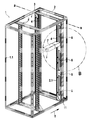
- FIG. 1 shows a perspective front view of an embodiment of the switch cabinet arrangement
- FIG. 2 shows a detail enlargement of FIG. 1 ;
- FIG. 3 shows a perspective rear view of the embodiment according to FIGS. 1 and 2 ;
- FIG. 4 shows a detail view of FIG. 3 ;
- FIG. 5 shows a perspective view into the interior of an air supply channel
- FIG. 6 shows a perspective outside view of the air supply channel according to FIG. 5 .
- FIG. 1 shows a switch cabinet arrangement which has a switch cabinet 1 with a rack 1 . 1 .
- the flat parts covering the rack 1 . 1 are not represented.
- the foremost side of the rack 1 . 1 forms the door side, while the facing side forms the back side of the switch cabinet 1 . Accordingly, in FIG. 1 the depth direction T is indicated.
- a first and a second installation frame 2 are accommodated, which in each case form a 19 ′′ installation plane for 19 ′′ switch cabinet fixtures such as servers and the like.
- the installation frames 2 in each case have two vertical profiles 4 that are parallel and at a distance from each other and that are connected at the ends to one another by horizontal rails which in turn are then connected to the horizontal profiles of the rack 1 . 1 , in order to arrange the installation frame 2 in the interior of the switch cabinet 1 and at a certain grid spacing in the depth direction, which is predetermined by the system perforation of the horizontal profiles of the rack 1 . 1 .
- the rear installation frame 2 in the representation has a partition 5 which extends from one of the vertical profiles 4 in the direction of the side wall of the switch cabinet 1 , in order to thus partition off the accommodation space 3 for the switch cabinet fixtures from an area which is formed behind the rear installation frame 2 and the back wall of the switch cabinet 1 , and into which cooling air can be injected.
- the partition 5 can have a brush strip 11 on its longitudinal edge facing the switch cabinet side wall, brush strip which is used as sealing element.
- the partition 5 has a plurality of perforations 6 that are vertically separated from one another and separated from one another by webs, in order to confer in this manner sufficient stability to the partition 5 formed, for example, as a sheet metal part.
- the air supply channel 7 represented is fluidically connected via its air inlet side to one of the perforations 6 .
- On its front side facing the air inlet side the air supply channel 7 has a passage 9 for the introduction of supply or data lines.
- FIG. 2 The installation of the air supply channel 7 on the vertical profile 4 of the installation frame 2 as well as the supply of the supply or data line is shown more precisely in FIG. 2 .
- the supply or data line 13 is introduced via the passage 9 formed on the front side 10 of the air supply channel 7 into the interior of the air supply channel 7 .
- the front side 10 has a wall section 10 . 1 in which the passage 9 is formed, wherein the wall section 10 . 1 is oriented by an angle ⁇ of approximately 135° relative to the longitudinal direction x of the air supply channel 7 , in order to simplify the cable introduction.
- FIG. 2 moreover shows the vertical profile 4 of the rear installation frame 2 according to FIG.
- the air supply channel 7 can be connected, for example, by a clip to the vertical profile 4 . It is also possible to provide that cage nuts are inserted into the vertical profile 4 , which are used for screwing the air supply channel 7 to the vertical profile 4 .
- the air supply channel 7 does not completely cover the opening cross section of the perforation 6 of the partition 5 . It is possible to provide that, if needed, in the opening cross sections of the perforation 6 that are not covered by the represented air supply channel 7 , additional air supply channels 7 are arranged in order to supply cooling air to switch cabinet fixtures located higher in the vertical direction or deeper. However, it is also possible to provide that the opening cross sections of the perforation 6 that are not covered by an air supply channel 7 are closed by a blind plug or if desired by a cover that can be engaged in the perforations 6 .
- the partition 5 can be produced as a shaped sheet metal part or from an injection molded plastic.
- a sealing element 11 is put on, which can be a brush strip, for example, in order to seal the partition 5 with respect to a side wall (not shown) of the switch cabinet 1 .
- FIGS. 3 and 4 show the switch cabinet arrangement according to FIGS. 1 and 2 in the rear view.
- FIG. 3 one can see that, via the sealing elements 11 formed on the facing vertical profiles 4 , an area between the back wall and the rear installation frame 2 is partitioned off, which is used, for example, for injecting cooling air via a cooling apparatus, so that the cooling air provided by the cooling apparatus can be provided in a targeted manner via the perforations 6 and the air supply channels 7 to the switch cabinet fixtures.
- the switch cabinet fixtures are arranged between the vertical profiles 4 of the installation frame. To the extent that the entire installation height of the installation frame is not equipped with fixtures, the areas that remain free can be covered with blind covers in order to prevent an undesired cooling air pressure loss.
- FIG. 4 shows that the vertical profile 4 of the installation frame 2 has, adjoining the partition 5 , a vertical profile side 4 . 1 with a system perforation 4 . 2 extending in vertical direction and consisting of regularly spaced attachment accommodations for the installation of the air supply channel 7 .
- the vertical profile side 4 . 1 is one of three side walls of a profile projection of the vertical profile 4 , of which two are connected parallel to one another via a third profile side.
- the air supply channel 7 can now be moved only vertically, that is to say it can be moved along the perforations 6 , so that the air supply channel 7 , when it has been put on the profile protrusion, can be immobilized via the system perforation in the projection in a desired position.
- the air supply channel 7 is composed of a first and a second channel section 7 . 1 , 7 . 2 , which can be moved relative to one another in the longitudinal direction x of the air supply channel, in order to adjust in this way the air outlet cross section 8 in accordance with the existing air inlet cross section of the switch cabinet fixtures concerned.
- the second channel section 7 . 2 has a passage 9 through which a supply or data line 13 (see FIG. 2 ) can be introduced into the interior of the air supply channel.
- the air supply channel 7 has an inlet cross section 15 through which cooling air is introduced into the air supply channel 7 .
- the outlet cross section 8 of the air supply channel 7 is designed to be larger than the air inlet cross section 15 , so that the air supply channel moreover has the function of a diffuser.
- Adjoining the air inlet cross section 15 the recess 14 is formed, through which the air supply channel 7 can be slid onto a vertical profile 4 of an installation frame 2 (see also FIGS. 2 and 4 ).
- attachment accommodations 13 which lead into the recess 14 , so that, via the latter, the air supply channel 7 can be secured, for example, by screw connection, to the profile protrusion inserted into the recess 14 .
Landscapes
- Engineering & Computer Science (AREA)
- Microelectronics & Electronic Packaging (AREA)
- Computer Hardware Design (AREA)
- General Engineering & Computer Science (AREA)
- Physics & Mathematics (AREA)
- Thermal Sciences (AREA)
- Cooling Or The Like Of Electrical Apparatus (AREA)
- Patch Boards (AREA)
Applications Claiming Priority (3)
| Application Number | Priority Date | Filing Date | Title |
|---|---|---|---|
| DE202015101339.6 | 2015-03-16 | ||
| DE202015101339U | 2015-03-16 | ||
| DE202015101339.6U DE202015101339U1 (de) | 2015-03-16 | 2015-03-16 | Schaltschrankanordnung |
Publications (2)
| Publication Number | Publication Date |
|---|---|
| US20160278243A1 US20160278243A1 (en) | 2016-09-22 |
| US9769961B2 true US9769961B2 (en) | 2017-09-19 |
Family
ID=53045925
Family Applications (1)
| Application Number | Title | Priority Date | Filing Date |
|---|---|---|---|
| US15/066,641 Active US9769961B2 (en) | 2015-03-16 | 2016-03-10 | Switch cabinet arrangement |
Country Status (3)
| Country | Link |
|---|---|
| US (1) | US9769961B2 (fr) |
| EP (1) | EP3071004B1 (fr) |
| DE (1) | DE202015101339U1 (fr) |
Cited By (4)
| Publication number | Priority date | Publication date | Assignee | Title |
|---|---|---|---|---|
| US20180014433A1 (en) * | 2015-05-07 | 2018-01-11 | Dhk Storage, Llc | Computer Server Heat Regulation Utilizing Integrated Precision Air Flow |
| USD812025S1 (en) * | 2013-09-03 | 2018-03-06 | Abb S.P.A. | Cabinet for electrical switchboards |
| US10869405B1 (en) * | 2020-01-15 | 2020-12-15 | Dell Products, L.P. | Routing power and data cables to information handling system racks in a data center |
| US12155184B2 (en) | 2019-03-15 | 2024-11-26 | Rittal Gmbh & Co. Kg | Gripper for automated wiring |
Families Citing this family (5)
| Publication number | Priority date | Publication date | Assignee | Title |
|---|---|---|---|---|
| DE102013101507A1 (de) * | 2013-02-15 | 2014-08-21 | Rittal Gmbh & Co. Kg | Kombinierter Kabel- und Luftkanal für die Schaltschrankklimatisierung sowie ein entsprechender Schaltschrank |
| DE102015105482B4 (de) | 2015-04-10 | 2019-02-07 | Rittal Gmbh & Co. Kg | Schaltschrank oder Rack zur Aufnahme elektrischer Energiespeicher, insbesondere Batterien, und eine entsprechende Schaltschrank- oder Rackanordnung |
| DE202016100789U1 (de) | 2016-02-16 | 2016-05-11 | Rittal Gmbh & Co. Kg | Schaltschrankanordnung mit Schottung |
| US10251304B1 (en) * | 2017-09-20 | 2019-04-02 | Mitek Corp,. Inc. | Lightweight electronics rack |
| CN108347867A (zh) * | 2018-04-26 | 2018-07-31 | 苏州弗士曼精密机械有限公司 | 一种机箱冷却装置 |
Citations (31)
| Publication number | Priority date | Publication date | Assignee | Title |
|---|---|---|---|---|
| US20030235035A1 (en) * | 2002-06-20 | 2003-12-25 | Wintersteen Douglas Charles | Computer enclosure air distribution system |
| US20040114326A1 (en) * | 2002-12-12 | 2004-06-17 | 3M Innovative Properties Company | Outdoor electronic equipment cabinet |
| US20040217072A1 (en) * | 2003-04-30 | 2004-11-04 | Bash Cullen Edwin | Louvered rack |
| US20050225936A1 (en) * | 2002-03-28 | 2005-10-13 | Tony Day | Cooling of a data centre |
| US20080266789A1 (en) * | 2007-04-30 | 2008-10-30 | Hruby Kevin L | Telecommunication cabinet with airflow ducting |
| US20080316702A1 (en) * | 2007-05-17 | 2008-12-25 | Chatsworth Products, Inc. | Exhaust air duct with adjustable filler panel assemblies |
| US20090061755A1 (en) * | 2007-08-28 | 2009-03-05 | Panduit Corp. | Intake Duct |
| WO2009042735A1 (fr) | 2007-09-25 | 2009-04-02 | Blade Network Technologies, Inc. | Appareil permettant de changer extérieurement la direction de l'air circulant à travers un équipement électronique |
| US20100033930A1 (en) * | 2008-08-06 | 2010-02-11 | Hitachi, Ltd. | Storage apparatus, fan device, and controller unit device |
| US20100172092A1 (en) * | 2009-01-05 | 2010-07-08 | Chatsworth Products, Inc. | Electronic equipment enclosure with side-to-side airflow control system |
| US20110026225A1 (en) * | 2009-07-31 | 2011-02-03 | Sun Microsystems, Inc. | Method and Apparatus for Liquid Cooling Computer Equipment |
| US20110063778A1 (en) * | 2008-05-20 | 2011-03-17 | Thomas Wayne Brouillard | Rack Mounted Cooling Unit |
| US8040673B2 (en) * | 2008-09-08 | 2011-10-18 | Chatsworth Products, Inc. | Ducted exhaust equipment enclosure |
| US20120008275A1 (en) * | 2008-10-17 | 2012-01-12 | Doll Wade J | Air conditioning systems for computer systems and associated methods |
| US8107238B2 (en) * | 2005-09-19 | 2012-01-31 | Chatsworth Products, Inc. | Ducted exhaust equipment enclosure |
| US20130039006A1 (en) * | 2011-08-09 | 2013-02-14 | Hon Hai Precision Industry Co., Ltd. | Server rack assembly |
| DE202013100336U1 (de) | 2013-01-24 | 2013-03-11 | Vkf Renzel Gmbh | Einkaufswagen mit entnehmbarem Behälter |
| US20130063894A1 (en) * | 2011-09-08 | 2013-03-14 | Inventec Corporation | Server |
| US20130070416A1 (en) * | 2011-09-15 | 2013-03-21 | Panduit Corp. | Thermal Management System |
| US20130188309A1 (en) * | 2010-09-20 | 2013-07-25 | Amazon Technologies, Inc. | System with rack-mounted ac fans |
| DE202013100338U1 (de) | 2013-01-24 | 2013-08-01 | Rittal Gmbh & Co. Kg | Kanalsystem für die gezielte Kühlluftzuführung in einem Schaltschrank |
| US20130229769A1 (en) * | 2012-03-05 | 2013-09-05 | Xu Yang | Data center container with draining mechanism |
| US20130242503A1 (en) * | 2012-03-15 | 2013-09-19 | Hon Hai Precision Industry Co., Ltd. | Apparatus for receiving servers |
| US20130342991A1 (en) * | 2012-06-20 | 2013-12-26 | Zheng-Heng Sun | Server rack |
| US20140002988A1 (en) * | 2011-05-25 | 2014-01-02 | Hewlett-Packard Development Company, L.P. | Blade computer system |
| US20140085811A1 (en) * | 2012-09-21 | 2014-03-27 | Inventec Corporation | Rack server system |
| US20140085810A1 (en) * | 2012-09-21 | 2014-03-27 | Inventec Corporation | Server system |
| US20140177164A1 (en) * | 2012-12-26 | 2014-06-26 | Oracle International Corporation | Airflow management system for cabinet having field replaceable units |
| US20140285966A1 (en) * | 2013-03-20 | 2014-09-25 | Hon Hai Precision Industry Co., Ltd. | Server cabinet |
| US20150208554A1 (en) * | 2012-09-28 | 2015-07-23 | Hewlett-Packard Development Company, L.P. | Plenums for removable modules |
| US20160088775A1 (en) * | 2014-09-22 | 2016-03-24 | Dell Products, L.P. | Bi-directional airflow heatsink |
Family Cites Families (4)
| Publication number | Priority date | Publication date | Assignee | Title |
|---|---|---|---|---|
| DE29623065U1 (de) | 1996-11-19 | 1997-10-02 | Rittal-Werk Rudolf Loh GmbH & Co. KG, 35745 Herborn | Rahmenprofil für ein Rahmengestell eines Schaltschrankes |
| DE29623551U1 (de) | 1996-11-19 | 1998-10-01 | Rittal-Werk Rudolf Loh GmbH & Co. KG, 35745 Herborn | Schaltschrank |
| DE19801720C1 (de) | 1998-01-19 | 1999-07-15 | Loh Kg Rittal Werk | Verbindungselement |
| DE102006034000A1 (de) | 2006-07-22 | 2008-01-31 | Rittal Gmbh & Co. Kg | Schaltschrank oder Rack |
-
2015
- 2015-03-16 DE DE202015101339.6U patent/DE202015101339U1/de not_active Expired - Lifetime
-
2016
- 2016-01-29 EP EP16153297.3A patent/EP3071004B1/fr active Active
- 2016-03-10 US US15/066,641 patent/US9769961B2/en active Active
Patent Citations (33)
| Publication number | Priority date | Publication date | Assignee | Title |
|---|---|---|---|---|
| US20050225936A1 (en) * | 2002-03-28 | 2005-10-13 | Tony Day | Cooling of a data centre |
| US7867070B2 (en) * | 2002-03-28 | 2011-01-11 | American Power Conversion Corporation | Data center cooling |
| US20110105010A1 (en) * | 2002-03-28 | 2011-05-05 | American Power Conversion Corporation | Data center cooling |
| US20030235035A1 (en) * | 2002-06-20 | 2003-12-25 | Wintersteen Douglas Charles | Computer enclosure air distribution system |
| US20040114326A1 (en) * | 2002-12-12 | 2004-06-17 | 3M Innovative Properties Company | Outdoor electronic equipment cabinet |
| US20040217072A1 (en) * | 2003-04-30 | 2004-11-04 | Bash Cullen Edwin | Louvered rack |
| US8107238B2 (en) * | 2005-09-19 | 2012-01-31 | Chatsworth Products, Inc. | Ducted exhaust equipment enclosure |
| US20080266789A1 (en) * | 2007-04-30 | 2008-10-30 | Hruby Kevin L | Telecommunication cabinet with airflow ducting |
| US20080316702A1 (en) * | 2007-05-17 | 2008-12-25 | Chatsworth Products, Inc. | Exhaust air duct with adjustable filler panel assemblies |
| US20090061755A1 (en) * | 2007-08-28 | 2009-03-05 | Panduit Corp. | Intake Duct |
| WO2009042735A1 (fr) | 2007-09-25 | 2009-04-02 | Blade Network Technologies, Inc. | Appareil permettant de changer extérieurement la direction de l'air circulant à travers un équipement électronique |
| US20110063778A1 (en) * | 2008-05-20 | 2011-03-17 | Thomas Wayne Brouillard | Rack Mounted Cooling Unit |
| US20100033930A1 (en) * | 2008-08-06 | 2010-02-11 | Hitachi, Ltd. | Storage apparatus, fan device, and controller unit device |
| US8040673B2 (en) * | 2008-09-08 | 2011-10-18 | Chatsworth Products, Inc. | Ducted exhaust equipment enclosure |
| US20120008275A1 (en) * | 2008-10-17 | 2012-01-12 | Doll Wade J | Air conditioning systems for computer systems and associated methods |
| US20100172092A1 (en) * | 2009-01-05 | 2010-07-08 | Chatsworth Products, Inc. | Electronic equipment enclosure with side-to-side airflow control system |
| US20110026225A1 (en) * | 2009-07-31 | 2011-02-03 | Sun Microsystems, Inc. | Method and Apparatus for Liquid Cooling Computer Equipment |
| US20130188309A1 (en) * | 2010-09-20 | 2013-07-25 | Amazon Technologies, Inc. | System with rack-mounted ac fans |
| US20140002988A1 (en) * | 2011-05-25 | 2014-01-02 | Hewlett-Packard Development Company, L.P. | Blade computer system |
| US20130039006A1 (en) * | 2011-08-09 | 2013-02-14 | Hon Hai Precision Industry Co., Ltd. | Server rack assembly |
| US20130063894A1 (en) * | 2011-09-08 | 2013-03-14 | Inventec Corporation | Server |
| US20130070416A1 (en) * | 2011-09-15 | 2013-03-21 | Panduit Corp. | Thermal Management System |
| US20130229769A1 (en) * | 2012-03-05 | 2013-09-05 | Xu Yang | Data center container with draining mechanism |
| US20130242503A1 (en) * | 2012-03-15 | 2013-09-19 | Hon Hai Precision Industry Co., Ltd. | Apparatus for receiving servers |
| US20130342991A1 (en) * | 2012-06-20 | 2013-12-26 | Zheng-Heng Sun | Server rack |
| US20140085810A1 (en) * | 2012-09-21 | 2014-03-27 | Inventec Corporation | Server system |
| US20140085811A1 (en) * | 2012-09-21 | 2014-03-27 | Inventec Corporation | Rack server system |
| US20150208554A1 (en) * | 2012-09-28 | 2015-07-23 | Hewlett-Packard Development Company, L.P. | Plenums for removable modules |
| US20140177164A1 (en) * | 2012-12-26 | 2014-06-26 | Oracle International Corporation | Airflow management system for cabinet having field replaceable units |
| DE202013100338U1 (de) | 2013-01-24 | 2013-08-01 | Rittal Gmbh & Co. Kg | Kanalsystem für die gezielte Kühlluftzuführung in einem Schaltschrank |
| DE202013100336U1 (de) | 2013-01-24 | 2013-03-11 | Vkf Renzel Gmbh | Einkaufswagen mit entnehmbarem Behälter |
| US20140285966A1 (en) * | 2013-03-20 | 2014-09-25 | Hon Hai Precision Industry Co., Ltd. | Server cabinet |
| US20160088775A1 (en) * | 2014-09-22 | 2016-03-24 | Dell Products, L.P. | Bi-directional airflow heatsink |
Cited By (4)
| Publication number | Priority date | Publication date | Assignee | Title |
|---|---|---|---|---|
| USD812025S1 (en) * | 2013-09-03 | 2018-03-06 | Abb S.P.A. | Cabinet for electrical switchboards |
| US20180014433A1 (en) * | 2015-05-07 | 2018-01-11 | Dhk Storage, Llc | Computer Server Heat Regulation Utilizing Integrated Precision Air Flow |
| US12155184B2 (en) | 2019-03-15 | 2024-11-26 | Rittal Gmbh & Co. Kg | Gripper for automated wiring |
| US10869405B1 (en) * | 2020-01-15 | 2020-12-15 | Dell Products, L.P. | Routing power and data cables to information handling system racks in a data center |
Also Published As
| Publication number | Publication date |
|---|---|
| EP3071004A1 (fr) | 2016-09-21 |
| DE202015101339U1 (de) | 2015-04-20 |
| EP3071004B1 (fr) | 2018-03-14 |
| US20160278243A1 (en) | 2016-09-22 |
Similar Documents
| Publication | Publication Date | Title |
|---|---|---|
| US9769961B2 (en) | Switch cabinet arrangement | |
| US11304339B2 (en) | Universal inlet duct system for side air intake equipment | |
| US10277014B2 (en) | Profiled frame of a frame structure for an electrical enclosure or a distribution cabinet | |
| FI3504382T3 (en) | Fixing profile allowing the air passage and assembly of ceiling comprising such a profile | |
| US11044831B2 (en) | Electrical enclosure arrangement comprising an electrical enclosure line and a cooling device connected into the line | |
| JP6385455B2 (ja) | 自動車の換気装置用エアフィルタ | |
| US20110001408A1 (en) | Network Cabinet Fitting System | |
| US8119915B2 (en) | Cable management patch panel system with vertical ducting | |
| CA3021059A1 (fr) | Arrangement d'armoire de commande, comprenant un dispositif refroidisseur qui est recu dans un logement de l'armoire de commande | |
| US11125465B2 (en) | Furnace | |
| US8848367B2 (en) | Thermal management system | |
| UA128668C2 (uk) | Комутаційна шафа з рамним каркасом і компонентом внутрішньої комплектації і відповідне компонування комутаційної шафи, а також відповідний компонент внутрішньої комплектації | |
| US20110173906A1 (en) | Floor gland | |
| US20050193930A1 (en) | Frame profile section | |
| EP3402318A1 (fr) | Rack à 4 montants ayant des régions d'admission/d'échappement intégrées | |
| MX2011000966A (es) | Salida de aire de techo para instalaciones tecnicas de aire acondicionado. | |
| US10166843B2 (en) | Vehicle air-conditioning apparatus | |
| US10358822B2 (en) | Integrated cross bar with mounting tab for grille | |
| ES2355230B1 (es) | Cuerpo empotrable para grifos termostáticos. | |
| KR101598541B1 (ko) | 관로 격벽장치 | |
| KR200416705Y1 (ko) | 환기장치용 공기 유도 안내구 | |
| US20150368895A1 (en) | Mounting bracket for grille | |
| JP2019175895A (ja) | ブランクパネル | |
| CN106924767A (zh) | 消毒柜 | |
| KR20100112331A (ko) | 슬라이드 커버를 구비한 케이블 정리용 하우징 일체형 파워서플라이 유닛 |
Legal Events
| Date | Code | Title | Description |
|---|---|---|---|
| AS | Assignment |
Owner name: RITTAL GMBH & CO. KG, GERMANY Free format text: ASSIGNMENT OF ASSIGNORS INTEREST;ASSIGNORS:BACH, MICHAEL;BLOECHER, GUNTHER;SCHMITTGALL, VOLKER;SIGNING DATES FROM 20160212 TO 20160215;REEL/FRAME:037951/0749 |
|
| STCF | Information on status: patent grant |
Free format text: PATENTED CASE |
|
| MAFP | Maintenance fee payment |
Free format text: PAYMENT OF MAINTENANCE FEE, 4TH YEAR, LARGE ENTITY (ORIGINAL EVENT CODE: M1551); ENTITY STATUS OF PATENT OWNER: LARGE ENTITY Year of fee payment: 4 |
|
| MAFP | Maintenance fee payment |
Free format text: PAYMENT OF MAINTENANCE FEE, 8TH YEAR, LARGE ENTITY (ORIGINAL EVENT CODE: M1552); ENTITY STATUS OF PATENT OWNER: LARGE ENTITY Year of fee payment: 8 |