EP3071004B1 - Systeme d'armoire electrique - Google Patents
Systeme d'armoire electrique Download PDFInfo
- Publication number
- EP3071004B1 EP3071004B1 EP16153297.3A EP16153297A EP3071004B1 EP 3071004 B1 EP3071004 B1 EP 3071004B1 EP 16153297 A EP16153297 A EP 16153297A EP 3071004 B1 EP3071004 B1 EP 3071004B1
- Authority
- EP
- European Patent Office
- Prior art keywords
- switch cabinet
- air supply
- supply channel
- arrangement according
- partition
- Prior art date
- Legal status (The legal status is an assumption and is not a legal conclusion. Google has not performed a legal analysis and makes no representation as to the accuracy of the status listed.)
- Active
Links
Images



Classifications
-
- H—ELECTRICITY
- H05—ELECTRIC TECHNIQUES NOT OTHERWISE PROVIDED FOR
- H05K—PRINTED CIRCUITS; CASINGS OR CONSTRUCTIONAL DETAILS OF ELECTRIC APPARATUS; MANUFACTURE OF ASSEMBLAGES OF ELECTRICAL COMPONENTS
- H05K7/00—Constructional details common to different types of electric apparatus
- H05K7/20—Modifications to facilitate cooling, ventilating, or heating
- H05K7/20709—Modifications to facilitate cooling, ventilating, or heating for server racks or cabinets; for data centers, e.g. 19-inch computer racks
- H05K7/20754—Air circulating in closed loop within cabinets
-
- H—ELECTRICITY
- H05—ELECTRIC TECHNIQUES NOT OTHERWISE PROVIDED FOR
- H05K—PRINTED CIRCUITS; CASINGS OR CONSTRUCTIONAL DETAILS OF ELECTRIC APPARATUS; MANUFACTURE OF ASSEMBLAGES OF ELECTRICAL COMPONENTS
- H05K7/00—Constructional details common to different types of electric apparatus
- H05K7/20—Modifications to facilitate cooling, ventilating, or heating
- H05K7/20709—Modifications to facilitate cooling, ventilating, or heating for server racks or cabinets; for data centers, e.g. 19-inch computer racks
- H05K7/20718—Forced ventilation of a gaseous coolant
- H05K7/20736—Forced ventilation of a gaseous coolant within cabinets for removing heat from server blades
-
- H—ELECTRICITY
- H05—ELECTRIC TECHNIQUES NOT OTHERWISE PROVIDED FOR
- H05K—PRINTED CIRCUITS; CASINGS OR CONSTRUCTIONAL DETAILS OF ELECTRIC APPARATUS; MANUFACTURE OF ASSEMBLAGES OF ELECTRICAL COMPONENTS
- H05K7/00—Constructional details common to different types of electric apparatus
- H05K7/14—Mounting supporting structure in casing or on frame or rack
- H05K7/1485—Servers; Data center rooms, e.g. 19-inch computer racks
- H05K7/1488—Cabinets therefor, e.g. chassis or racks or mechanical interfaces between blades and support structures
- H05K7/1489—Cabinets therefor, e.g. chassis or racks or mechanical interfaces between blades and support structures characterized by the mounting of blades therein, e.g. brackets, rails, trays
-
- H—ELECTRICITY
- H05—ELECTRIC TECHNIQUES NOT OTHERWISE PROVIDED FOR
- H05K—PRINTED CIRCUITS; CASINGS OR CONSTRUCTIONAL DETAILS OF ELECTRIC APPARATUS; MANUFACTURE OF ASSEMBLAGES OF ELECTRICAL COMPONENTS
- H05K7/00—Constructional details common to different types of electric apparatus
- H05K7/20—Modifications to facilitate cooling, ventilating, or heating
- H05K7/20009—Modifications to facilitate cooling, ventilating, or heating using a gaseous coolant in electronic enclosures
- H05K7/20136—Forced ventilation, e.g. by fans
- H05K7/20145—Means for directing air flow, e.g. ducts, deflectors, plenum or guides
Definitions
- the invention relates to a switchgear assembly comprising a control cabinet with a mounting frame accommodated therein, which limits a receiving space for control cabinet installations, and a cooling air guide, wherein the mounting frame has two parallel spaced vertical profiles that define a first mounting plane for the cabinet installations, and wherein the cooling air duct a Has partition, which extends between the vertical profiles and a respective associated cabinet side wall, wherein the partition has at least one opening, is connected to the at least one air supply duct, which leads via the opening into the air supply duct introduced cooling air in the direction of the receiving space, is fluidly connected.
- a cabinet arrangement is from the US 2008/266789 A1 known. Similar arrangements also describe the DE 10 2007 034 437 A1 and the WO 2009/042735 A1 ,
- Generic switchgear assemblies are often designed to provide cold air in a region between the mounting frame and the rear wall of the cabinet from a refrigerator which is sucked in rearwardly from the cabinet components, such as IT equipment such as servers and the like, and blown out as heated air at the front ,
- IT devices that are designed for the lateraldeluftansaugung or -Inblasung.
- a channel system for the targeted cooling air supply known.
- a cooling air channel is provided with, if necessary, openings to be opened instead of the partition or in this integrated, to which an air supply duct can be connected to supply the cooling air of a specific control cabinet component targeted.
- the Channel system however, has the disadvantage that it is designed comparatively expensive. It is therefore the object of the invention to further develop a generic switchgear assembly such that it enables the targeted cooling air supply for control cabinet installations with lateral cooling air supply with the simplest possible means.
- At least one supply or data line is routed through the air supply channel.
- the invention proposes to use the existing in generic switchgear assemblies already existing partition between the mounting frame and the cabinet housing for the cooling air supply by being provided with openings to which air supply ducts can be connected as needed.
- the apertures have an opening cross section which is greater than the inlet cross section of the air supply channel. It can further be provided that the openings in areas where no air supply duct is connected with a closure, such as a blind plug, can be closed.
- the bulkhead may have a plurality of openings in the vertical direction, which are separated by webs, in order to give the bulkhead a sufficient torsional strength.
- the air supply duct may be designed to divert the cooling air flowing in via its air inlet side by substantially 90 °.
- the air supply channel may further be formed as a diffuser, that is, it may have a larger cooling air outlet than the cooling air inlet. Furthermore, it can be provided that the receiving space, the cooling air is supplied via a cooling air outlet of the air supply duct laterally and parallel to the mounting plane.
- the air supply channel can provide a deflection of the cooling air flow flowing out through the openings by substantially 90 °.
- the supply or data line may be from a cabinet installation received in the receiving space through the air supply duct and through the breakthrough in the partition be passed.
- the air supply duct may have a passage for the introduction of a supply or data line into the interior of the air supply duct.
- the passage can be formed on a side facing away from the bulkhead front of the air supply duct.
- the air supply channel can thus also have a cable management function, for example, in order to realize an orderly cable routing in the case of a large number of control cabinet installations arranged vertically one above the other on the mounting frame.
- the air supply channel can be made telescopic in its longitudinal direction and thereby have two channel sections which are mutually displaceable. It can now also be provided that the air supply channel via the first channel portion is in fluid communication with the opening, wherein the second channel portion having the front with the passage for the cable passage.
- the passage is formed in a wall portion of the front of the air supply duct which is at an angle of 90 ° ⁇ ⁇ 180 °, preferably at an angle of 110 ° ⁇ ⁇ 150 ° and more preferably at an angle of 135 ° the longitudinal direction (telescopic direction) of the air supply channel is arranged.
- the switchgear assembly may comprise a switchgear cabinet having a quarter-shaped frame formed of four vertical and eight horizontal struts.
- a frame is for example from the DE 196 47 814 C2 or from the DE 296 23 065 U1 known.
- the two cabinet side walls are connected to the frame frame flat parts, as it is known from DE 198 01 720 C1 is known. It can now be provided that the Partition between the vertical profiles of the mounting frame and the respective associated flat part extends and is in contact via a sealing element with the flat part.
- the bulkhead can have a sheet metal part or consist of such, which is connected to one of the vertical profiles, preferably screwed, wherein on one of the cabinet side wall facing the longitudinal edge of the sheet metal part, the sealing element is attached.
- the sealing element may be, for example, a brush strip.
- the mounting frame may be a mounting frame for the 19 "switch cabinet interior fitting
- the air supply duct can also be connected directly to the partitioning device
- tool-free fastening means such as clips or the like, are preferably used in order to be able to vary the vertical arrangement of the air supply duct without great effort.
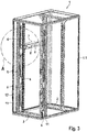
- FIG. 1 shows a cabinet assembly having a cabinet 1 with a frame set 1.1.
- the frame 1.1 paneling flat parts are not shown.
- the foremost side of the frame 1.1 in the illustration forms the door side, while the opposite side forms the back of the cabinet 1. Accordingly, in FIG. 1 the depth direction T indicated.
- a first and a second mounting frame 2 are added, each forming a 19 "- mounting level for 19" cabinet installations, such as servers and the same.
- the mounting frame 2 each have two parallel spaced vertical profiles 4, which are connected to one another via horizontal rails, which in turn are then connected to the horizontal profiles of the frame 1.1 to the mounting frame 2 in the interior of the cabinet 1 and at a certain pitch in the depth direction, the through the system perforation of the horizontal profiles of the frame 1.1. is given to arrange.
- the rear mounting frame 2 in the illustration has a partition 5 which extends from one of the vertical profiles 4 in the direction of the side wall of the cabinet 1, so as to accommodate the cabinet 3 accommodating space from an area behind the rear mounting frame 2 and the rear wall of the cabinet 1 is formed and can be injected into the cooling air to foreclose.
- the partition 5 may have a brush strip 11 on its longitudinal edge facing the cabinet side wall, which serves as a sealing element.
- the partition 5 has vertically spaced from each other a plurality of apertures 6, which are separated by webs, so as to give the example designed as a sheet metal part partition 5 sufficient stability.
- the illustrated air supply channel 7 is fluidly connected via its air inlet side with one of the apertures 6. At its front side facing the air inlet side, the air supply channel 7 has a passage 9 for the introduction of supply or data lines.
- FIG. 2 The assembly of the air supply channel 7 on the vertical profile 4 of the mounting frame 2 and the supply of the supply or data lines is more accurate in FIG. 2 shown.
- the supply or data line 13 is introduced into the interior of the air supply duct 7 via the passage 9 formed on the front side 10 of the air supply duct 7.
- the front side 10 has a wall portion 10.1 in which the passage 9 is formed, the wall portion 10.1 being oriented at an angle ⁇ of about 135 ° to the longitudinal direction x of the air supply passage 7 to facilitate the cable entry.
- the FIG. 2 further shows the vertical profile 4 of the rear mounting frame 2 according to FIG. 1 , which has a system holes formed along its vertical direction of circular passages and rectangular passages.
- the air supply channel 7 may be connected, for example via clips with the vertical profile 4. It can also be provided that cage nuts are inserted into the vertical profile 4, which serve for screwing the air supply channel 7 with the vertical profile 4.
- the air supply channel 7 does not completely cover the opening cross section of the opening 6 of the partition 5. It can be provided that, if necessary, 6 further air supply ducts 7 are arranged in the uncovered by the represented Lucaszu Georgiakanals opening cross sections of the opening 6 to supply in the vertical direction higher or lower cabinet heaters cooling air. But it can also be provided that the not covered by an air supply duct 7 opening cross sections of the openings 6 are closed by a blind plug or a snap-in optionally in the openings 6 cover.
- the partition 5 can be made as a sheet metal part or injection molded plastic.
- a sealing element 11 is attached, which may for example be a brush strip to seal the partition 5 against a (not shown) side wall of the cabinet 1.
- FIG. 3 shows the cabinet assembly according to FIG. 1 and 2 in the rear view.
- FIG. 3 It can be seen that over the formed on the opposite vertical profiles 4 sealing elements 11 a region between the rear wall and the rear mounting frame 2 is sealed off, which serves for example for the cooling air injection via a cooling device, so that the cooling air provided by the cooling device can be specifically provided via the openings 6 and the air supply ducts 7 the control cabinet installations.
- the control cabinet internals are arranged between the vertical sections 4 of the mounting frame. Unless the full height of the mounting frame is fitted with internals, the remaining areas can be closed with blind covers to prevent unwanted loss of cooling air pressure.
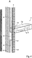
- FIG. 4 shows that the vertical profile 4 of the mounting frame 2 adjacent to the bulkhead 5 has a vertical profile side 4.1 with a vertically extending system holes 4.2 from regularly spaced mounting receptacles for mounting the air supply duct 7.
- the vertical profile side 4.1 is one of three side walls of a profile projection of the vertical profile 4, two of which are connected in parallel spaced from one another via a third profile side.
- the profile projection engages in mounted Lucaszu Georgia experts 7 in a Ausnhemung 14 on the air inlet side of the first channel section 7.1 of the air supply channel 7, whereby a pre-positioning of the air supply duct 7 is achieved.
- the air supply channel 7 is composed of a first and a second channel section 7.1, 7.2, which are mutually displaceable in the longitudinal direction x of the air supply duct, so as to adjust the air outlet section 8 corresponding to the existing air inlet cross-section of the relevant control cabinet installations.
- the second channel section 7.2 has, in an angled wall section 10.1 on the front side 10, a passage 9, via which a supply or data line 13 (see FIG FIG. 2 ) can be introduced into the interior of the air supply duct.
- the air supply channel 7 has an inlet cross section 15, is introduced via the cooling air into the air supply channel 7.
- the outlet section 8 of Air supply channel 7 is formed larger than the air inlet cross section 15, so that the air supply channel further has the function of a diffuser.
- Associated with the recess 14 are fastening receivers 13 which open into the recess 14, so that the air supply channel 7 can be fixed, for example screwed, to the profile projection pushed into the recess 14.
Landscapes
- Engineering & Computer Science (AREA)
- Microelectronics & Electronic Packaging (AREA)
- Computer Hardware Design (AREA)
- General Engineering & Computer Science (AREA)
- Physics & Mathematics (AREA)
- Thermal Sciences (AREA)
- Cooling Or The Like Of Electrical Apparatus (AREA)
- Patch Boards (AREA)
Claims (12)
- Disposition d'armoire de commande qui comprend une armoire de commande (1) avec un châssis de montage (2) logé à l'intérieur, qui comprend un espace de logement (3) pour des aménagements d'armoire de commande et un guidage d'air de refroidissement (5, 6, 7), le châssis de montage (2) comprenant deux profilés verticaux (4) parallèles, qui définissent un premier plan de fixation (a) pour les aménagements d'armoire et le guidage d'air de refroidissement (5, 6, 7) comprenant une cloison (5), qui s'étend entre les profilés verticaux (4) et une paroi latérale d'armoire de commande (12) correspondante, la cloison (5) comprenant au moins un perçage (6), au niveau duquel au moins un canal d'alimentation en air (7), qui conduit l'air de refroidissement introduit par le perçage (6) dans le canal d'alimentation en air (7) en direction de l'espace de logement (3), est raccordé de manière fluidique, caractérisée en ce qu'au moins une conduite d'alimentation ou de données (13) est guidée à travers le canal d'alimentation en air (7).
- Disposition d'armoire de commande selon la revendication 1, dans laquelle l'air de refroidissement est introduit dans l'espace de logement (3) par l'intermédiaire d'une sortie d'air de refroidissement (8) du canal d'alimentation en air (7) sur le côté et parallèlement au plan de fixation (a).
- Disposition d'armoire de commande selon la revendication 1, dans laquelle la conduite d'alimentation ou de données (13) est guidée par un aménagement logé dans l'espace de logement (3) à travers le canal d'alimentation en air (7) et à travers le perçage (6) dans la cloison (5).
- Disposition d'armoire de commande selon la revendication 1, dans laquelle le canal d'alimentation en air (7) comprend un passage (9) pour l'introduction de la conduite d'alimentation ou de données (13) à l'intérieur du canal d'alimentation en air (7).
- Disposition d'armoire de commande selon la revendication 4, dans laquelle le passage (9) est réalisé au niveau d'un côté avant (10) du canal d'alimentation en air (7) opposé à la cloison (5).
- Disposition d'armoire de commande selon la revendication 5, dans laquelle le canal d'alimentation en air (7) est réalisé de manière télescopique dans sa direction longitudinale (x), avec une première portion de canal (7.1), par l'intermédiaire de laquelle le canal d'alimentation en air (7) est relié de manière fluidique avec le perçage (6) et avec une deuxième portion de canal (7.2), qui comprend le côté avant (10) avec le passage (9).
- Disposition d'armoire de commande selon l'une des revendications 4 à 6, dans laquelle le passage (9) est réalisé dans une portion de paroi (10.1) du côté avant (10) du canal d'alimentation en air (7), qui est disposé avec un angle (α) 90° < α < 180°, de préférence avec un angle (α) 110° < α < 150° et plus particulièrement de préférence avec un angle (α) de 135° par rapport à la direction longitudinale (x).
- Disposition d'armoire de commande selon l'une des revendications précédentes, dans laquelle l'armoire de commande comprend un châssis parallélépipédique (1.1) qui est constitué de quatre entretoises verticales et de huit entretoises horizontales, les deux parois latérales de l'armoire de commande (12) étant des pièces plates reliées par le châssis (1.1) et la cloison (5) s'étendant entre les profilés verticaux (4) du châssis de montage (2) et la pièce plate correspondante et étant en contact avec la pièce plate par l'intermédiaire d'un élément d'étanchéité (11).
- Disposition d'armoire de commande selon la revendication 8, dans laquelle la cloison (5) comprend une pièce en tôle, qui est reliée avec un des profilés verticaux (4), de préférence vissée, l'élément d'étanchéité (11) étant enfiché sur une arête longitudinale de la pièce en tôle orientée vers la paroi latérale de l'armoire de commande (12).
- Disposition d'armoire de commande selon la revendication 8 ou 9, dans laquelle l'élément d'étanchéité (11) est un joint balai.
- Disposition d'armoire de commande selon l'une des revendications précédentes, dans laquelle le châssis de montage (2) est un châssis de montage pour l'extension intérieure d'armoire de commande de 19".
- Disposition d'armoire de commande selon l'une des revendications précédentes, dans laquelle le profilé vertical (4) du châssis de montage (2) comprend, à proximité de la cloison (5), ou à une distance fixe de celle-ci, un côté profilé vertical (4.1) avec un système de perforation (4.2) s'étendant dans la direction verticale, constitué de logements de fixation disposés à intervalles réguliers pour le montage de l'au moins un canal d'alimentation en air (7).
Applications Claiming Priority (1)
| Application Number | Priority Date | Filing Date | Title |
|---|---|---|---|
| DE202015101339.6U DE202015101339U1 (de) | 2015-03-16 | 2015-03-16 | Schaltschrankanordnung |
Publications (2)
| Publication Number | Publication Date |
|---|---|
| EP3071004A1 EP3071004A1 (fr) | 2016-09-21 |
| EP3071004B1 true EP3071004B1 (fr) | 2018-03-14 |
Family
ID=53045925
Family Applications (1)
| Application Number | Title | Priority Date | Filing Date |
|---|---|---|---|
| EP16153297.3A Active EP3071004B1 (fr) | 2015-03-16 | 2016-01-29 | Systeme d'armoire electrique |
Country Status (3)
| Country | Link |
|---|---|
| US (1) | US9769961B2 (fr) |
| EP (1) | EP3071004B1 (fr) |
| DE (1) | DE202015101339U1 (fr) |
Families Citing this family (9)
| Publication number | Priority date | Publication date | Assignee | Title |
|---|---|---|---|---|
| DE102013101507A1 (de) * | 2013-02-15 | 2014-08-21 | Rittal Gmbh & Co. Kg | Kombinierter Kabel- und Luftkanal für die Schaltschrankklimatisierung sowie ein entsprechender Schaltschrank |
| USD743358S1 (en) * | 2013-09-03 | 2015-11-17 | Abb S.P.A. | Cabinet for electrical switchboards |
| DE102015105482B4 (de) | 2015-04-10 | 2019-02-07 | Rittal Gmbh & Co. Kg | Schaltschrank oder Rack zur Aufnahme elektrischer Energiespeicher, insbesondere Batterien, und eine entsprechende Schaltschrank- oder Rackanordnung |
| US9832912B2 (en) * | 2015-05-07 | 2017-11-28 | Dhk Storage, Llc | Computer server heat regulation utilizing integrated precision air flow |
| DE202016100789U1 (de) | 2016-02-16 | 2016-05-11 | Rittal Gmbh & Co. Kg | Schaltschrankanordnung mit Schottung |
| US10251304B1 (en) * | 2017-09-20 | 2019-04-02 | Mitek Corp,. Inc. | Lightweight electronics rack |
| CN108347867A (zh) * | 2018-04-26 | 2018-07-31 | 苏州弗士曼精密机械有限公司 | 一种机箱冷却装置 |
| DE102019106710B4 (de) | 2019-03-15 | 2022-03-17 | Rittal Gmbh & Co. Kg | Greifer für die automatisierte Verdrahtung elektrischer Komponenten einer elektrischen Schaltanlage, ein entsprechender Roboter und ein entsprechendes Verfahren |
| US10869405B1 (en) * | 2020-01-15 | 2020-12-15 | Dell Products, L.P. | Routing power and data cables to information handling system racks in a data center |
Family Cites Families (35)
| Publication number | Priority date | Publication date | Assignee | Title |
|---|---|---|---|---|
| DE29623065U1 (de) | 1996-11-19 | 1997-10-02 | Rittal-Werk Rudolf Loh GmbH & Co. KG, 35745 Herborn | Rahmenprofil für ein Rahmengestell eines Schaltschrankes |
| DE29623551U1 (de) | 1996-11-19 | 1998-10-01 | Rittal-Werk Rudolf Loh GmbH & Co. KG, 35745 Herborn | Schaltschrank |
| DE19801720C1 (de) | 1998-01-19 | 1999-07-15 | Loh Kg Rittal Werk | Verbindungselement |
| GB0207382D0 (en) * | 2002-03-28 | 2002-05-08 | Holland Heating Uk Ltd | Computer cabinet |
| US6944020B2 (en) * | 2002-06-20 | 2005-09-13 | Delphi Technologies, Inc. | Computer enclosure air distribution system |
| US6788535B2 (en) * | 2002-12-12 | 2004-09-07 | 3M Innovative Properties Company | Outdoor electronic equipment cabinet |
| US7031154B2 (en) * | 2003-04-30 | 2006-04-18 | Hewlett-Packard Development Company, L.P. | Louvered rack |
| US7804685B2 (en) * | 2005-09-19 | 2010-09-28 | Chatsworth Products, Inc. | Ducted exhaust equipment enclosure |
| US8107238B2 (en) * | 2005-09-19 | 2012-01-31 | Chatsworth Products, Inc. | Ducted exhaust equipment enclosure |
| DE102006034000A1 (de) | 2006-07-22 | 2008-01-31 | Rittal Gmbh & Co. Kg | Schaltschrank oder Rack |
| US7764495B2 (en) * | 2007-04-30 | 2010-07-27 | Adc Telecommunications, Inc. | Telecommunication cabinet with airflow ducting |
| US7697285B2 (en) * | 2007-05-17 | 2010-04-13 | Chatsworth Products, Inc. | Electronic equipment enclosure with exhaust air duct and adjustable filler panel assemblies |
| US20090061755A1 (en) * | 2007-08-28 | 2009-03-05 | Panduit Corp. | Intake Duct |
| WO2009042735A1 (fr) * | 2007-09-25 | 2009-04-02 | Blade Network Technologies, Inc. | Appareil permettant de changer extérieurement la direction de l'air circulant à travers un équipement électronique |
| US20110063778A1 (en) * | 2008-05-20 | 2011-03-17 | Thomas Wayne Brouillard | Rack Mounted Cooling Unit |
| JP2010039826A (ja) * | 2008-08-06 | 2010-02-18 | Hitachi Ltd | ストレージ装置、ファン装置、及びコントローラユニット装置 |
| US8081459B2 (en) * | 2008-10-17 | 2011-12-20 | Cray Inc. | Air conditioning systems for computer systems and associated methods |
| EP2205054A1 (fr) * | 2009-01-05 | 2010-07-07 | Chatsworth Product, INC. | Fermeture d'équipement électronique avec système de contrôle du débit d'air bord à bord |
| US8035972B2 (en) * | 2009-07-31 | 2011-10-11 | Oracle America, Inc. | Method and apparatus for liquid cooling computer equipment |
| US8400765B2 (en) * | 2010-09-20 | 2013-03-19 | Amazon Technologies, Inc. | System with air flow under data storage devices |
| DE112011105140T5 (de) * | 2011-05-25 | 2014-01-09 | Hewlett-Packard Development Company, L.P. | Blade-Computersystem |
| CN102929360A (zh) * | 2011-08-09 | 2013-02-13 | 鸿富锦精密工业(深圳)有限公司 | 服务器机柜 |
| CN102999089B (zh) * | 2011-09-08 | 2015-11-25 | 英业达股份有限公司 | 服务器 |
| US8848367B2 (en) * | 2011-09-15 | 2014-09-30 | Panduit Corp. | Thermal management system |
| CN103287760A (zh) * | 2012-03-05 | 2013-09-11 | 鸿富锦精密工业(深圳)有限公司 | 集装箱 |
| CN103313578A (zh) * | 2012-03-15 | 2013-09-18 | 鸿富锦精密工业(深圳)有限公司 | 服务器机柜 |
| CN103513720A (zh) * | 2012-06-20 | 2014-01-15 | 鸿富锦精密工业(深圳)有限公司 | 服务器机架 |
| CN103677101A (zh) * | 2012-09-21 | 2014-03-26 | 英业达科技有限公司 | 服务器 |
| CN103677156A (zh) * | 2012-09-21 | 2014-03-26 | 英业达科技有限公司 | 服务器机架系统 |
| EP2901242A4 (fr) * | 2012-09-28 | 2016-05-25 | Hewlett Packard Development Co | Plénums pour mobiles amovibles |
| US8982554B2 (en) * | 2012-12-26 | 2015-03-17 | Oracle International Corporation | Airflow management system for cabinet having field replaceable units |
| DE202013100336U1 (de) | 2013-01-24 | 2013-03-11 | Vkf Renzel Gmbh | Einkaufswagen mit entnehmbarem Behälter |
| DE202013100338U1 (de) | 2013-01-24 | 2013-08-01 | Rittal Gmbh & Co. Kg | Kanalsystem für die gezielte Kühlluftzuführung in einem Schaltschrank |
| CN104066299B (zh) * | 2013-03-20 | 2017-04-05 | 鸿富锦精密工业(深圳)有限公司 | 机柜 |
| US9643233B2 (en) * | 2014-09-22 | 2017-05-09 | Dell Products, L.P. | Bi-directional airflow heatsink |
-
2015
- 2015-03-16 DE DE202015101339.6U patent/DE202015101339U1/de not_active Expired - Lifetime
-
2016
- 2016-01-29 EP EP16153297.3A patent/EP3071004B1/fr active Active
- 2016-03-10 US US15/066,641 patent/US9769961B2/en active Active
Non-Patent Citations (1)
| Title |
|---|
| None * |
Also Published As
| Publication number | Publication date |
|---|---|
| EP3071004A1 (fr) | 2016-09-21 |
| US9769961B2 (en) | 2017-09-19 |
| DE202015101339U1 (de) | 2015-04-20 |
| US20160278243A1 (en) | 2016-09-22 |
Similar Documents
| Publication | Publication Date | Title |
|---|---|---|
| EP3071004B1 (fr) | Systeme d'armoire electrique | |
| DE102016107531B3 (de) | Schaltschrankanordnung mit einem in einem Schaltschrankgehäuse aufgenommenen Kühlgerät | |
| DE102009054011B4 (de) | Kühlanordnung für in einem Schaltschrank angeordnete elektrische Geräte | |
| DE202015105009U1 (de) | Frontplattenanordung eines Leistungsgeräts | |
| DE102014100417B3 (de) | Rahmenprofil für ein Rahmengestell eines Schaltschranks sowie Befestigungsclip für das Rahmenprofil | |
| DE102009057129A1 (de) | Belüftungsvorrichtung für Komponenten eines Elektronik- oder Computerschranks | |
| DE102010016489A1 (de) | Gehäuseteil für einen Schaltschrank | |
| EP2706633B1 (fr) | Insert pour ouvertures murales d'armoires d'installation | |
| DE102016124609A1 (de) | Verteilerkasten zum Einbau in eine Wandöffnung | |
| DE202018100613U1 (de) | Anordnung mit zwei über einen Anreihverbinder miteinander verbundenen Schaltschrankrahmengestellen | |
| DE102015116716B4 (de) | Verteilerblock mit Berührschutzanordnung | |
| DE202014000971U1 (de) | Profilsystem für Verglasungen | |
| EP2863497B1 (fr) | Armoire ou boîte de distribution de l'installation électrique de bâtiments | |
| DE202023100180U1 (de) | Zähler- und Verteilerschrank | |
| DE102017217673A1 (de) | Haushaltskältegerät mit Abdeckung eines Spalts zwischen einer Schäumtraverse und einer Elektronikbox | |
| DE202012009059U1 (de) | Luftauslass | |
| DE4205293A1 (de) | Verdrahtungskanal fuer schaltschraenke | |
| EP2418746A2 (fr) | Boîtier d'appareillage pour appareils dýinstallation | |
| DE102013110649A1 (de) | System zum Anordnen und Verdrahten von elektrischen Einheiten | |
| EP3217497B1 (fr) | Support d'appareil | |
| EP3672001B1 (fr) | Boîtier d'installation électrique | |
| CH713832B1 (de) | Befestigungsvorrichtung, Tür für einen Schaltschrank sowie ein Schaltschrank umfassend eine solche Tür. | |
| EP3499660B1 (fr) | Agencement comprenant un premier et un second rails support, un couvercle et un premier et un second dispositifs support, et boîtier de distribution | |
| DE102023207640A1 (de) | Rahmensystem zum Einbau in ein Arbeitsmöbel und Arbeitsmöbel | |
| DE202023102513U1 (de) | Kabelträger für einen Verteilerraum zur Aufnahme von Kabeln |
Legal Events
| Date | Code | Title | Description |
|---|---|---|---|
| PUAI | Public reference made under article 153(3) epc to a published international application that has entered the european phase |
Free format text: ORIGINAL CODE: 0009012 |
|
| AK | Designated contracting states |
Kind code of ref document: A1 Designated state(s): AL AT BE BG CH CY CZ DE DK EE ES FI FR GB GR HR HU IE IS IT LI LT LU LV MC MK MT NL NO PL PT RO RS SE SI SK SM TR |
|
| AX | Request for extension of the european patent |
Extension state: BA ME |
|
| STAA | Information on the status of an ep patent application or granted ep patent |
Free format text: STATUS: REQUEST FOR EXAMINATION WAS MADE |
|
| 17P | Request for examination filed |
Effective date: 20170316 |
|
| RBV | Designated contracting states (corrected) |
Designated state(s): AL AT BE BG CH CY CZ DE DK EE ES FI FR GB GR HR HU IE IS IT LI LT LU LV MC MK MT NL NO PL PT RO RS SE SI SK SM TR |
|
| GRAP | Despatch of communication of intention to grant a patent |
Free format text: ORIGINAL CODE: EPIDOSNIGR1 |
|
| STAA | Information on the status of an ep patent application or granted ep patent |
Free format text: STATUS: GRANT OF PATENT IS INTENDED |
|
| INTG | Intention to grant announced |
Effective date: 20170926 |
|
| GRAS | Grant fee paid |
Free format text: ORIGINAL CODE: EPIDOSNIGR3 |
|
| GRAA | (expected) grant |
Free format text: ORIGINAL CODE: 0009210 |
|
| STAA | Information on the status of an ep patent application or granted ep patent |
Free format text: STATUS: THE PATENT HAS BEEN GRANTED |
|
| AK | Designated contracting states |
Kind code of ref document: B1 Designated state(s): AL AT BE BG CH CY CZ DE DK EE ES FI FR GB GR HR HU IE IS IT LI LT LU LV MC MK MT NL NO PL PT RO RS SE SI SK SM TR |
|
| REG | Reference to a national code |
Ref country code: GB Ref legal event code: FG4D Free format text: NOT ENGLISH |
|
| REG | Reference to a national code |
Ref country code: CH Ref legal event code: EP Ref country code: AT Ref legal event code: REF Ref document number: 980060 Country of ref document: AT Kind code of ref document: T Effective date: 20180315 |
|
| REG | Reference to a national code |
Ref country code: IE Ref legal event code: FG4D Free format text: LANGUAGE OF EP DOCUMENT: GERMAN |
|
| REG | Reference to a national code |
Ref country code: DE Ref legal event code: R096 Ref document number: 502016000678 Country of ref document: DE |
|
| REG | Reference to a national code |
Ref country code: DE Ref legal event code: R082 Ref document number: 502016000678 Country of ref document: DE Representative=s name: BOEHMERT & BOEHMERT ANWALTSPARTNERSCHAFT MBB -, DE |
|
| REG | Reference to a national code |
Ref country code: NL Ref legal event code: FP |
|
| REG | Reference to a national code |
Ref country code: LT Ref legal event code: MG4D |
|
| PG25 | Lapsed in a contracting state [announced via postgrant information from national office to epo] |
Ref country code: HR Free format text: LAPSE BECAUSE OF FAILURE TO SUBMIT A TRANSLATION OF THE DESCRIPTION OR TO PAY THE FEE WITHIN THE PRESCRIBED TIME-LIMIT Effective date: 20180314 Ref country code: NO Free format text: LAPSE BECAUSE OF FAILURE TO SUBMIT A TRANSLATION OF THE DESCRIPTION OR TO PAY THE FEE WITHIN THE PRESCRIBED TIME-LIMIT Effective date: 20180614 Ref country code: FI Free format text: LAPSE BECAUSE OF FAILURE TO SUBMIT A TRANSLATION OF THE DESCRIPTION OR TO PAY THE FEE WITHIN THE PRESCRIBED TIME-LIMIT Effective date: 20180314 Ref country code: LT Free format text: LAPSE BECAUSE OF FAILURE TO SUBMIT A TRANSLATION OF THE DESCRIPTION OR TO PAY THE FEE WITHIN THE PRESCRIBED TIME-LIMIT Effective date: 20180314 Ref country code: CY Free format text: LAPSE BECAUSE OF FAILURE TO SUBMIT A TRANSLATION OF THE DESCRIPTION OR TO PAY THE FEE WITHIN THE PRESCRIBED TIME-LIMIT Effective date: 20180314 |
|
| PG25 | Lapsed in a contracting state [announced via postgrant information from national office to epo] |
Ref country code: LV Free format text: LAPSE BECAUSE OF FAILURE TO SUBMIT A TRANSLATION OF THE DESCRIPTION OR TO PAY THE FEE WITHIN THE PRESCRIBED TIME-LIMIT Effective date: 20180314 Ref country code: SE Free format text: LAPSE BECAUSE OF FAILURE TO SUBMIT A TRANSLATION OF THE DESCRIPTION OR TO PAY THE FEE WITHIN THE PRESCRIBED TIME-LIMIT Effective date: 20180314 Ref country code: GR Free format text: LAPSE BECAUSE OF FAILURE TO SUBMIT A TRANSLATION OF THE DESCRIPTION OR TO PAY THE FEE WITHIN THE PRESCRIBED TIME-LIMIT Effective date: 20180615 Ref country code: RS Free format text: LAPSE BECAUSE OF FAILURE TO SUBMIT A TRANSLATION OF THE DESCRIPTION OR TO PAY THE FEE WITHIN THE PRESCRIBED TIME-LIMIT Effective date: 20180314 Ref country code: BG Free format text: LAPSE BECAUSE OF FAILURE TO SUBMIT A TRANSLATION OF THE DESCRIPTION OR TO PAY THE FEE WITHIN THE PRESCRIBED TIME-LIMIT Effective date: 20180614 |
|
| PG25 | Lapsed in a contracting state [announced via postgrant information from national office to epo] |
Ref country code: MT Free format text: LAPSE BECAUSE OF FAILURE TO SUBMIT A TRANSLATION OF THE DESCRIPTION OR TO PAY THE FEE WITHIN THE PRESCRIBED TIME-LIMIT Effective date: 20180314 |
|
| PG25 | Lapsed in a contracting state [announced via postgrant information from national office to epo] |
Ref country code: RO Free format text: LAPSE BECAUSE OF FAILURE TO SUBMIT A TRANSLATION OF THE DESCRIPTION OR TO PAY THE FEE WITHIN THE PRESCRIBED TIME-LIMIT Effective date: 20180314 Ref country code: EE Free format text: LAPSE BECAUSE OF FAILURE TO SUBMIT A TRANSLATION OF THE DESCRIPTION OR TO PAY THE FEE WITHIN THE PRESCRIBED TIME-LIMIT Effective date: 20180314 Ref country code: AL Free format text: LAPSE BECAUSE OF FAILURE TO SUBMIT A TRANSLATION OF THE DESCRIPTION OR TO PAY THE FEE WITHIN THE PRESCRIBED TIME-LIMIT Effective date: 20180314 Ref country code: PL Free format text: LAPSE BECAUSE OF FAILURE TO SUBMIT A TRANSLATION OF THE DESCRIPTION OR TO PAY THE FEE WITHIN THE PRESCRIBED TIME-LIMIT Effective date: 20180314 Ref country code: ES Free format text: LAPSE BECAUSE OF FAILURE TO SUBMIT A TRANSLATION OF THE DESCRIPTION OR TO PAY THE FEE WITHIN THE PRESCRIBED TIME-LIMIT Effective date: 20180314 |
|
| PG25 | Lapsed in a contracting state [announced via postgrant information from national office to epo] |
Ref country code: CZ Free format text: LAPSE BECAUSE OF FAILURE TO SUBMIT A TRANSLATION OF THE DESCRIPTION OR TO PAY THE FEE WITHIN THE PRESCRIBED TIME-LIMIT Effective date: 20180314 Ref country code: SK Free format text: LAPSE BECAUSE OF FAILURE TO SUBMIT A TRANSLATION OF THE DESCRIPTION OR TO PAY THE FEE WITHIN THE PRESCRIBED TIME-LIMIT Effective date: 20180314 Ref country code: SM Free format text: LAPSE BECAUSE OF FAILURE TO SUBMIT A TRANSLATION OF THE DESCRIPTION OR TO PAY THE FEE WITHIN THE PRESCRIBED TIME-LIMIT Effective date: 20180314 |
|
| REG | Reference to a national code |
Ref country code: DE Ref legal event code: R097 Ref document number: 502016000678 Country of ref document: DE |
|
| PG25 | Lapsed in a contracting state [announced via postgrant information from national office to epo] |
Ref country code: PT Free format text: LAPSE BECAUSE OF FAILURE TO SUBMIT A TRANSLATION OF THE DESCRIPTION OR TO PAY THE FEE WITHIN THE PRESCRIBED TIME-LIMIT Effective date: 20180716 |
|
| PLBE | No opposition filed within time limit |
Free format text: ORIGINAL CODE: 0009261 |
|
| STAA | Information on the status of an ep patent application or granted ep patent |
Free format text: STATUS: NO OPPOSITION FILED WITHIN TIME LIMIT |
|
| PG25 | Lapsed in a contracting state [announced via postgrant information from national office to epo] |
Ref country code: DK Free format text: LAPSE BECAUSE OF FAILURE TO SUBMIT A TRANSLATION OF THE DESCRIPTION OR TO PAY THE FEE WITHIN THE PRESCRIBED TIME-LIMIT Effective date: 20180314 |
|
| 26N | No opposition filed |
Effective date: 20181217 |
|
| PG25 | Lapsed in a contracting state [announced via postgrant information from national office to epo] |
Ref country code: SI Free format text: LAPSE BECAUSE OF FAILURE TO SUBMIT A TRANSLATION OF THE DESCRIPTION OR TO PAY THE FEE WITHIN THE PRESCRIBED TIME-LIMIT Effective date: 20180314 |
|
| PG25 | Lapsed in a contracting state [announced via postgrant information from national office to epo] |
Ref country code: MC Free format text: LAPSE BECAUSE OF FAILURE TO SUBMIT A TRANSLATION OF THE DESCRIPTION OR TO PAY THE FEE WITHIN THE PRESCRIBED TIME-LIMIT Effective date: 20180314 |
|
| REG | Reference to a national code |
Ref country code: CH Ref legal event code: PL |
|
| PG25 | Lapsed in a contracting state [announced via postgrant information from national office to epo] |
Ref country code: LU Free format text: LAPSE BECAUSE OF NON-PAYMENT OF DUE FEES Effective date: 20190129 |
|
| REG | Reference to a national code |
Ref country code: BE Ref legal event code: MM Effective date: 20190131 |
|
| REG | Reference to a national code |
Ref country code: IE Ref legal event code: MM4A |
|
| PG25 | Lapsed in a contracting state [announced via postgrant information from national office to epo] |
Ref country code: BE Free format text: LAPSE BECAUSE OF NON-PAYMENT OF DUE FEES Effective date: 20190131 |
|
| PG25 | Lapsed in a contracting state [announced via postgrant information from national office to epo] |
Ref country code: CH Free format text: LAPSE BECAUSE OF NON-PAYMENT OF DUE FEES Effective date: 20190131 Ref country code: LI Free format text: LAPSE BECAUSE OF NON-PAYMENT OF DUE FEES Effective date: 20190131 |
|
| PG25 | Lapsed in a contracting state [announced via postgrant information from national office to epo] |
Ref country code: IE Free format text: LAPSE BECAUSE OF NON-PAYMENT OF DUE FEES Effective date: 20190129 |
|
| PG25 | Lapsed in a contracting state [announced via postgrant information from national office to epo] |
Ref country code: TR Free format text: LAPSE BECAUSE OF FAILURE TO SUBMIT A TRANSLATION OF THE DESCRIPTION OR TO PAY THE FEE WITHIN THE PRESCRIBED TIME-LIMIT Effective date: 20180314 |
|
| PG25 | Lapsed in a contracting state [announced via postgrant information from national office to epo] |
Ref country code: IS Free format text: LAPSE BECAUSE OF FAILURE TO SUBMIT A TRANSLATION OF THE DESCRIPTION OR TO PAY THE FEE WITHIN THE PRESCRIBED TIME-LIMIT Effective date: 20180714 |
|
| PG25 | Lapsed in a contracting state [announced via postgrant information from national office to epo] |
Ref country code: HU Free format text: LAPSE BECAUSE OF FAILURE TO SUBMIT A TRANSLATION OF THE DESCRIPTION OR TO PAY THE FEE WITHIN THE PRESCRIBED TIME-LIMIT; INVALID AB INITIO Effective date: 20160129 |
|
| REG | Reference to a national code |
Ref country code: AT Ref legal event code: MM01 Ref document number: 980060 Country of ref document: AT Kind code of ref document: T Effective date: 20210129 |
|
| PG25 | Lapsed in a contracting state [announced via postgrant information from national office to epo] |
Ref country code: AT Free format text: LAPSE BECAUSE OF NON-PAYMENT OF DUE FEES Effective date: 20210129 |
|
| PG25 | Lapsed in a contracting state [announced via postgrant information from national office to epo] |
Ref country code: MK Free format text: LAPSE BECAUSE OF FAILURE TO SUBMIT A TRANSLATION OF THE DESCRIPTION OR TO PAY THE FEE WITHIN THE PRESCRIBED TIME-LIMIT Effective date: 20180314 |
|
| P01 | Opt-out of the competence of the unified patent court (upc) registered |
Effective date: 20230525 |
|
| PGFP | Annual fee paid to national office [announced via postgrant information from national office to epo] |
Ref country code: NL Payment date: 20260121 Year of fee payment: 11 |
|
| PGFP | Annual fee paid to national office [announced via postgrant information from national office to epo] |
Ref country code: GB Payment date: 20260122 Year of fee payment: 11 |
|
| PGFP | Annual fee paid to national office [announced via postgrant information from national office to epo] |
Ref country code: DE Payment date: 20260120 Year of fee payment: 11 |
|
| PGFP | Annual fee paid to national office [announced via postgrant information from national office to epo] |
Ref country code: IT Payment date: 20260130 Year of fee payment: 11 |
|
| PGFP | Annual fee paid to national office [announced via postgrant information from national office to epo] |
Ref country code: FR Payment date: 20260121 Year of fee payment: 11 |