US9786974B2 - Tunable band-pass filter - Google Patents
Tunable band-pass filter Download PDFInfo
- Publication number
- US9786974B2 US9786974B2 US14/436,009 US201314436009A US9786974B2 US 9786974 B2 US9786974 B2 US 9786974B2 US 201314436009 A US201314436009 A US 201314436009A US 9786974 B2 US9786974 B2 US 9786974B2
- Authority
- US
- United States
- Prior art keywords
- pass filter
- tunable band
- conductor
- movable
- filter according
- Prior art date
- Legal status (The legal status is an assumption and is not a legal conclusion. Google has not performed a legal analysis and makes no representation as to the accuracy of the status listed.)
- Active, expires
Links
- 239000004020 conductor Substances 0.000 claims abstract description 76
- 239000000463 material Substances 0.000 claims description 13
- 230000008878 coupling Effects 0.000 abstract description 13
- 238000010168 coupling process Methods 0.000 abstract description 13
- 238000005859 coupling reaction Methods 0.000 abstract description 13
- 230000008859 change Effects 0.000 abstract description 12
- 230000000694 effects Effects 0.000 description 4
- 229910052751 metal Inorganic materials 0.000 description 4
- 239000002184 metal Substances 0.000 description 4
- RYGMFSIKBFXOCR-UHFFFAOYSA-N Copper Chemical compound [Cu] RYGMFSIKBFXOCR-UHFFFAOYSA-N 0.000 description 3
- 229910052802 copper Inorganic materials 0.000 description 3
- 239000010949 copper Substances 0.000 description 3
- 229910052782 aluminium Inorganic materials 0.000 description 2
- XAGFODPZIPBFFR-UHFFFAOYSA-N aluminium Chemical compound [Al] XAGFODPZIPBFFR-UHFFFAOYSA-N 0.000 description 2
- 239000000919 ceramic Substances 0.000 description 2
- 238000010586 diagram Methods 0.000 description 2
- 239000003989 dielectric material Substances 0.000 description 2
- 238000005516 engineering process Methods 0.000 description 2
- 239000011347 resin Substances 0.000 description 2
- 229920005989 resin Polymers 0.000 description 2
- 229910002113 barium titanate Inorganic materials 0.000 description 1
- 230000008901 benefit Effects 0.000 description 1
- 230000005540 biological transmission Effects 0.000 description 1
- 150000001875 compounds Chemical class 0.000 description 1
- 230000006866 deterioration Effects 0.000 description 1
- 230000007246 mechanism Effects 0.000 description 1
- 229910052761 rare earth metal Inorganic materials 0.000 description 1
- -1 rare-earth barium titanate Chemical class 0.000 description 1
- 230000009466 transformation Effects 0.000 description 1
- 238000000844 transformation Methods 0.000 description 1
Images



Classifications
-
- H—ELECTRICITY
- H01—ELECTRIC ELEMENTS
- H01P—WAVEGUIDES; RESONATORS, LINES, OR OTHER DEVICES OF THE WAVEGUIDE TYPE
- H01P1/00—Auxiliary devices
- H01P1/20—Frequency-selective devices, e.g. filters
- H01P1/201—Filters for transverse electromagnetic waves
- H01P1/205—Comb or interdigital filters; Cascaded coaxial cavities
- H01P1/2053—Comb or interdigital filters; Cascaded coaxial cavities the coaxial cavity resonators being disposed parall to each other
-
- H—ELECTRICITY
- H01—ELECTRIC ELEMENTS
- H01P—WAVEGUIDES; RESONATORS, LINES, OR OTHER DEVICES OF THE WAVEGUIDE TYPE
- H01P1/00—Auxiliary devices
- H01P1/20—Frequency-selective devices, e.g. filters
- H01P1/201—Filters for transverse electromagnetic waves
- H01P1/205—Comb or interdigital filters; Cascaded coaxial cavities
-
- H—ELECTRICITY
- H01—ELECTRIC ELEMENTS
- H01P—WAVEGUIDES; RESONATORS, LINES, OR OTHER DEVICES OF THE WAVEGUIDE TYPE
- H01P1/00—Auxiliary devices
- H01P1/20—Frequency-selective devices, e.g. filters
- H01P1/201—Filters for transverse electromagnetic waves
- H01P1/205—Comb or interdigital filters; Cascaded coaxial cavities
- H01P1/2056—Comb filters or interdigital filters with metallised resonator holes in a dielectric block
-
- H—ELECTRICITY
- H01—ELECTRIC ELEMENTS
- H01P—WAVEGUIDES; RESONATORS, LINES, OR OTHER DEVICES OF THE WAVEGUIDE TYPE
- H01P1/00—Auxiliary devices
- H01P1/20—Frequency-selective devices, e.g. filters
- H01P1/207—Hollow waveguide filters
-
- H—ELECTRICITY
- H01—ELECTRIC ELEMENTS
- H01P—WAVEGUIDES; RESONATORS, LINES, OR OTHER DEVICES OF THE WAVEGUIDE TYPE
- H01P1/00—Auxiliary devices
- H01P1/20—Frequency-selective devices, e.g. filters
- H01P1/207—Hollow waveguide filters
- H01P1/208—Cascaded cavities; Cascaded resonators inside a hollow waveguide structure
- H01P1/2084—Cascaded cavities; Cascaded resonators inside a hollow waveguide structure with dielectric resonators
-
- H—ELECTRICITY
- H01—ELECTRIC ELEMENTS
- H01P—WAVEGUIDES; RESONATORS, LINES, OR OTHER DEVICES OF THE WAVEGUIDE TYPE
- H01P7/00—Resonators of the waveguide type
- H01P7/04—Coaxial resonators
-
- H—ELECTRICITY
- H01—ELECTRIC ELEMENTS
- H01P—WAVEGUIDES; RESONATORS, LINES, OR OTHER DEVICES OF THE WAVEGUIDE TYPE
- H01P7/00—Resonators of the waveguide type
- H01P7/06—Cavity resonators
Definitions
- the present invention relates to a band-pass filter used in a microwave and a millimeter wave, and, more particularly, to a tunable band-pass filter which can vary a resonance frequency.
- a band-pass filter In a radio communication system that performs transmission and reception using a microwave or a millimeter wave band, a band-pass filter is used to make only a signal of a desired frequency band pass, and to remove a signal of an unnecessary bandwidth.
- a band-pass filter is used at a plurality of center frequencies, there is a technological case described in patent literature 1.
- patent literature 1 there is disclosed a technology in which, in the metal housing of a semi-coaxial band-pass filter, a dielectric having a movable structure is provided and a resonance frequency of a resonator is made to be changed by moving this.
- the present invention has been made in view of the above-mentioned subject, and its object is to provide a tunable band-pass filter which is of low cost and of a simple structure, and which can change a resonance frequency of a resonator and a coupling amount (or, a coupling coefficient) between resonators easily.
- a tunable band-pass filter of the present invention comprises: a conductive chassis having a cavity resonator; a conductive cover to cover said cavity resonator; a resonant element arranged in said cavity resonator, one end of said resonant element being connected with said chassis and an other end being open end; and a movable conductor arranged in a space between said open end of said resonant element and said conductive cover.
- a tunable band-pass filter of the present invention it becomes possible to provide a tunable band-pass filter which is of low cost and of a simple structure, and which can change a resonance frequency of a resonator and a coupling amount between resonators easily.
- FIG. 1A is a perspective view showing a structure of a tunable band-pass filter of a first exemplary embodiment of the present invention.
- FIG. 1B is a sectional view showing a structure of a tunable band-pass filter of the first exemplary embodiment of the present invention.
- FIG. 2 is a perspective view showing a structure of a tunable band-pass filter of the first exemplary embodiment of the present invention.
- FIG. 3A is a perspective view showing a structure of a tunable band-pass filter of a second exemplary embodiment of the present invention.
- FIG. 3B is a perspective view showing a structure of a movable conductor part of the second exemplary embodiment of the present invention.
- FIG. 4 is a perspective view showing a structure of a tunable band-pass filter of a third exemplary embodiment of the present invention.
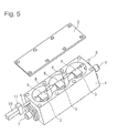
- FIG. 5 is a perspective view showing a structure of a tunable band-pass filter of a fourth exemplary embodiment of the present invention.
- FIG. 6 is a diagram showing a change of a resonance frequency of a tunable band-pass filter of the first exemplary embodiment of the present invention.
- FIG. 1A is a perspective view showing a structure of the first exemplary embodiment of the present invention.
- FIG. 1A there is indicated a band-pass filter including pieces of cavity resonator 20 of three stages.
- FIG. 1B indicates a sectional view of one piece of cavity resonator 20 among the pieces of cavity resonator 20 of three stages shown in FIG. 1A .
- the cavity resonator 20 is formed by a combination of a conductive chassis 1 and a conductive cover 2 .
- the cavity resonator 20 is of a cylindrical shape in FIG. 1A , it is not limited to a cylindrical shape, and it may be of another shape such as a prismatic shape.
- a window 21 of a structure made by cutting out a part of said cylindrical shape connects between each cavity resonator.
- the shape of the window 21 is not limited to the shape shown in FIG. 1A , and it may be of a shape besides this shape such as a cylinder, and the width of the cutout may be made to be about the same as the diameter of the cylinder of the cavity resonator 20 .
- a resonant element 3 is installed in the cavity resonator 20 , and its one end is connected to the conductive chassis 1 and the other end which is in the side facing the conductive cover 2 is open.
- a shape of the resonant element 3 a tabular shape, a prism or a column is possible, but not limited to these.
- a shape having a bend of an L letterform is also possible.
- material of the resonant element 3 a conductor or a dielectric is possible.
- an input terminal 7 for inputting a radio wave from outside and exciting said resonant element 3 and an output terminal 8 for outputting a radio wave which has passed said plurality of pieces of resonant element 3 outside the chassis In FIG. 1A , although a three-stage band-pass filter having three pieces of cavity resonator 20 is being disclosed, the number of pieces of cavity resonator 20 is not limited. Furthermore, the input terminal 7 and the output terminal 8 are ones which have been defined for convenience of description of operation, and thus it is possible to input a radio wave from the output terminal 8 , and take out a radio wave from the input terminal 7 .
- a conductor 5 made of a conductive member between each piece of resonant element 3 and the conductive cover 2 .
- An inexpensive metal such as copper and aluminum is possible as the material of the conductor 5 .
- the conductor 5 is arranged for each piece of cavity resonator 20 , and neighboring pieces of conductor 5 are connected by a non-conductive member 6 .
- As the non-conductive member 6 an inexpensive member such as ceramic and resin is possible.
- a connection member (no code attached in FIG. 1A ) may be provided between the non-conductive member 6 and the conductor 5 .
- the material of this connection member is optional, it is possible to use an inexpensive member of metal, ceramic or resin.
- the conductor 5 may be one having a size and a shape different for each piece of cavity resonator 20 .
- one end penetrates through the conductive chassis 1 by a support 9 , and, in addition, is made to be able to rotate about an axis to make the conductor 5 be movable from outside of the conductive chassis 1 of the band-pass filter.
- said one end does not need to penetrate.
- the other end penetrates through the conductive chassis 1 , is taken out outside, and is also made to be able to be axis-rotated.
- a stepping motor 10 or the like whose rotation is controlled by a computer can be used although manual may be acceptable.
- FIG. 1B is a diagram showing a sectional structure of one piece of cavity resonator 20 constituting a band-pass filter shown in FIG. 1A .
- the conductor 5 changes the capacity between the resonant element 3 and itself, and changes a resonance frequency. That is, by making the conductor 5 rotate, the capacity is changed by the interval between the conductor 5 and the resonant element 3 changing.
- a resonance frequency can be lowered along with rotation toward downward direction shown by the arrow in this figure.
- a frequency adjustment screw 4 to determine a standard resonance frequency of the cavity resonator 20 .
- FIG. 1A there is indicated a case where the frequency adjustment screw 4 does not exist.
- a band-pass filter is inexpensive because the conductor 5 made of metal such as copper and aluminum that is of low cost is used between each resonant element 3 and the conductive cover 2 . Furthermore, its structure is simple because the conductor 5 is not a dielectric member and thus is easy to be connected with a moving member, resulting in a holding member that would be necessary to join a dielectric member or the like being unnecessary. That is, as an effect of this exemplary embodiment, it is possible to provide a tunable band-pass filter which is of an inexpensive and of an easy structure, and which can change a resonance frequency of the cavity resonator 20 easily.
- FIG. 2 a tunable band-pass filter which can, in addition to the above effect, change a coupling amount between pieces of cavity resonator 20 is disclosed.
- a coupling amount or a coupling coefficient is related to a band of a band-pass filter, and when it is large, a band is wide, and, when it is small, a band is narrow.
- FIG. 2 indicates a structure in which a conductor 5 b that is similar to the conductor 5 is also provided in a position corresponding to the window 21 between pieces of cavity resonator 20 . Each piece of conductor 5 and a piece of conductor 5 b are connected via a non-conductive member 6 b.
- the conductor 5 b has a function to adjust a coupling amount between pieces of cavity resonator 20 . That is, a coupling amount between pieces of cavity resonator 20 changes according to a resonance frequency of the cavity resonator 20 being changed by the conductor 5 provided above the resonant element 3 . These pieces of conductor 5 b do not need to be of an identical size and a shape among respective pieces of cavity resonator 20 , and a size and a shape that are suitable for each of them can be selected.
- FIG. 6 indicates a state of a change in a resonance frequency of a band-pass filter of 8000 MHz band when, in the structure of FIG. 1A , rotating the conductor 5 in the downward direction of the arrow in the figure.
- the diameter of the cavity resonator 20 is 11 mm and the length 11 mm
- the width of the conductor 5 is 6 mm, the length 8 mm and the thickness 0.5 mm.
- the conductor 5 is in a position that is 8 mm from the bottom base of the cavity resonator 20
- the supporting point 12 of rotation is in a position that is offset from the center axis of the cavity resonator 20 by 3 mm.
- An inclined angle of 0 degree indicates a state that the conductor 5 is parallel to the conductive cover 2 .
- a resonance frequency has declined by about 300 MHz. There are almost no return-loss deteriorations during that span.
- a tunable band-pass filter which is inexpensive and of a simple structure and which can change a resonance frequency of a cavity resonator and a coupling amount between cavity resonators easily can be provided.
- FIG. 3A is a structure in which, in place of the conductor 5 of the first exemplary embodiment, a conductor 5 d shown in FIG. 3B is formed on the face of a non-conductive member 5 c in the side of the resonant element 3 .
- FIG. 3B shows a conductor structure used in FIG. 3A .
- a structure in which the conductor 5 d made of a metallic film such as copper is formed on the non-conductive member 5 c such as a printed wiring board can be used as a conductor.
- the conductor structure in which the conductor 5 d is formed onto the non-conductive member 5 c is connected by a connection member (no code attached in FIG. 3B ) forming a rotating shaft.
- a tunable band-pass filter which is inexpensive and of a simple structure, and which can change a resonance frequency of a cavity resonator and a coupling amount between cavity resonators easily can be provided.
- FIG. 4 is a structure in which, in place of the conductor 5 of the first exemplary embodiment, a conductor 5 e having a hole 13 which can let the frequency adjustment screw 4 through is provided. As a result, it also becomes possible to carry out frequency adjustment using the frequency adjustment screw 4 without influence of rotation of the conductor 5 e , and thus a variable range of a resonance frequency as a band-pass filter can be expanded.
- a tunable band-pass filter which is inexpensive and of a simple structure and which can change a resonance frequency of a cavity resonator and a coupling amount between cavity resonators easily can be provided.
- FIG. 5 is a structure in which, in place of the rotating mechanism of the conductor 5 of the first exemplary embodiment, a rotational movement of a motor 10 is converted into an up and down movement by a gear 11 to make the conductor 5 move up and down. By moving it up and down, a resonance frequency can be changed by a distance between the conductor 5 and the resonant element 3 changing.
- a tunable band-pass filter which is inexpensive and of a simple structure and which can change a resonance frequency of a cavity resonator and a coupling amount between cavity resonators easily can be provided.
- a tunable band-pass filter comprising: a conductive chassis having a cavity resonator; a conductive cover to cover said cavity resonator; a resonant element arranged in said cavity resonator, one end of said resonant element being connected with said chassis and an other end being open end; and a movable conductor arranged in a space between said open end of said resonant element and said conductive cover.
- the tunable band-pass filter according to supplementary note 1, wherein there are a plurality of pieces of said cavity resonator, and said movable conductor is also deployed in a space between said cavity resonator and said cavity resonator.
- the tunable band-pass filter according to any one of supplementary notes 1 to 2, wherein said movable conductor is connected by a non-conductivity material.
- the tunable band-pass filter according to any one of supplementary notes 1 to 3, wherein movement of said movable conductor is a rotating movement.
- the tunable band-pass filter according to any one of supplementary notes 1 to 3, wherein movement of said movable conductor is a linear movement.
- the tunable band-pass filter according to any one of supplementary notes 1 to 5, having a frequency adjustment screw screwed in from said conductive cover in a manner facing said resonant element.
- tunable band-pass filter according to any one of supplementary notes 1 to 7, wherein said movable conductor is a non-conductivity material having a metallic film formed on said non-conductivity material.
- tunable band-pass filter according to any one of supplementary notes 1 to 8, wherein said resonant element is one of a conductor and a dielectric, having a shape selected from a tabular shape, a prismatic column and a circular cylinder.
- a source of power of said movable conductor is a motor.
- the tunable band-pass filter according to supplementary note 10, wherein said motor is controlled by a computer.
- the present invention relates to a band-pass filter used in a microwave and a millimeter wave, and, more particularly, to a tunable band-pass filter which can vary a resonance frequency.
Landscapes
- Physics & Mathematics (AREA)
- Electromagnetism (AREA)
- Control Of Motors That Do Not Use Commutators (AREA)
Applications Claiming Priority (3)
| Application Number | Priority Date | Filing Date | Title |
|---|---|---|---|
| JP2012-233659 | 2012-10-23 | ||
| JP2012233659A JP6006079B2 (ja) | 2012-10-23 | 2012-10-23 | チューナブル帯域通過フィルタ |
| PCT/JP2013/006181 WO2014064911A1 (ja) | 2012-10-23 | 2013-10-18 | チューナブル帯域通過フィルタ |
Publications (2)
| Publication Number | Publication Date |
|---|---|
| US20150280298A1 US20150280298A1 (en) | 2015-10-01 |
| US9786974B2 true US9786974B2 (en) | 2017-10-10 |
Family
ID=50544296
Family Applications (1)
| Application Number | Title | Priority Date | Filing Date |
|---|---|---|---|
| US14/436,009 Active 2034-03-18 US9786974B2 (en) | 2012-10-23 | 2013-10-18 | Tunable band-pass filter |
Country Status (6)
| Country | Link |
|---|---|
| US (1) | US9786974B2 (de) |
| EP (1) | EP2913884B1 (de) |
| JP (1) | JP6006079B2 (de) |
| CN (1) | CN104756312A (de) |
| IN (1) | IN2015DN03044A (de) |
| WO (1) | WO2014064911A1 (de) |
Cited By (1)
| Publication number | Priority date | Publication date | Assignee | Title |
|---|---|---|---|---|
| US11431068B2 (en) * | 2020-05-26 | 2022-08-30 | Nec Corporation | Frequency variable filter and coupling method |
Families Citing this family (12)
| Publication number | Priority date | Publication date | Assignee | Title |
|---|---|---|---|---|
| WO2016075852A1 (ja) * | 2014-11-10 | 2016-05-19 | 日本電気株式会社 | バンドパスフィルタ、及び無線通信装置 |
| CN107204503B (zh) * | 2016-03-18 | 2020-05-05 | 通玉科技有限公司 | Rf滤波器 |
| KR101818109B1 (ko) | 2016-03-25 | 2018-01-12 | (주)에드모텍 | 삽입손실 특성을 개선한 주파수 가변 필터 |
| WO2017170120A1 (ja) | 2016-03-31 | 2017-10-05 | 日本電気株式会社 | チューナブル帯域通過フィルタ |
| US10763561B2 (en) | 2016-05-20 | 2020-09-01 | Nec Corporation | Band-pass filter and control method thereof |
| EP3711113B1 (de) * | 2017-11-16 | 2024-01-17 | RF Microtech S.r.l. | Abstimmbarer bandpassfilter |
| JP7303063B2 (ja) * | 2019-08-20 | 2023-07-04 | 日本電気株式会社 | 共振器及び製造方法 |
| US10790795B1 (en) * | 2019-12-25 | 2020-09-29 | Universal Microwave Technology, Inc. | Zeroing structure applicable to adjustable diplexer |
| KR102919910B1 (ko) * | 2020-07-09 | 2026-01-29 | 삼성전자주식회사 | 무선 통신 시스템에서 안테나 필터 및 이를 포함하는 전자 장치 |
| JP7681719B2 (ja) * | 2021-04-19 | 2025-05-22 | ケーエムダブリュ・インコーポレーテッド | スイッチング可能なフィルタ |
| CN115000656A (zh) * | 2022-04-13 | 2022-09-02 | 华南理工大学 | 基于同轴腔体谐振器的可调滤波器、可调双工器 |
| CN115101908B (zh) * | 2022-06-27 | 2024-04-05 | 苏州市协诚微波技术有限公司 | 一种金属滤波器及其组装方法 |
Citations (14)
| Publication number | Priority date | Publication date | Assignee | Title |
|---|---|---|---|---|
| US4459570A (en) * | 1980-08-29 | 1984-07-10 | Thomson-Csf | Ultra-high frequency filter with a dielectric resonator tunable in a large band width |
| JPS59121903U (ja) | 1984-01-19 | 1984-08-16 | トムソン−セ−エスエフ | 極超短波フィルタ |
| JPH07131217A (ja) | 1993-11-08 | 1995-05-19 | Kyocera Corp | 誘電体共振器 |
| JPH07263926A (ja) | 1994-03-25 | 1995-10-13 | Kyocera Corp | 誘電体共振器 |
| JPH09172304A (ja) | 1995-12-21 | 1997-06-30 | Fujitsu Ltd | コプレーナ線路のインピーダンス調整器 |
| JP2001257511A (ja) | 2000-03-14 | 2001-09-21 | Murata Mfg Co Ltd | 共振器、フィルタ、デュプレクサ、通信機装置 |
| JP2003318612A (ja) | 2002-04-23 | 2003-11-07 | Pearl Kogyo Kk | 整合装置 |
| CN1585188A (zh) | 2003-08-23 | 2005-02-23 | Kmw株式会社 | 可变射频频带滤波器 |
| WO2006075439A1 (ja) | 2005-01-11 | 2006-07-20 | Murata Manufacturing Co., Ltd. | チューナブルフィルタ、デュプレクサおよび通信機装置 |
| US20090058563A1 (en) | 2007-08-28 | 2009-03-05 | Ace Technology | Frequency Tunable Filter |
| US20090237185A1 (en) | 2008-03-04 | 2009-09-24 | Nokia Siemens Networks Oy | Variable radio frequency band filter |
| US20110133862A1 (en) | 2008-08-07 | 2011-06-09 | Dong-Wan Chun | Tunable filter capable of controlling tuning characteristics |
| JP2011142460A (ja) | 2010-01-06 | 2011-07-21 | Nippon Dengyo Kosaku Co Ltd | フィルタ特性自動調整方法 |
| US20120119850A1 (en) | 2010-11-12 | 2012-05-17 | Paeri Petri | Adjustable resonator filter |
-
2012
- 2012-10-23 JP JP2012233659A patent/JP6006079B2/ja not_active Expired - Fee Related
-
2013
- 2013-10-18 IN IN3044DEN2015 patent/IN2015DN03044A/en unknown
- 2013-10-18 EP EP13848804.4A patent/EP2913884B1/de not_active Not-in-force
- 2013-10-18 CN CN201380055643.XA patent/CN104756312A/zh active Pending
- 2013-10-18 US US14/436,009 patent/US9786974B2/en active Active
- 2013-10-18 WO PCT/JP2013/006181 patent/WO2014064911A1/ja not_active Ceased
Patent Citations (18)
| Publication number | Priority date | Publication date | Assignee | Title |
|---|---|---|---|---|
| US4459570A (en) * | 1980-08-29 | 1984-07-10 | Thomson-Csf | Ultra-high frequency filter with a dielectric resonator tunable in a large band width |
| JPS59121903U (ja) | 1984-01-19 | 1984-08-16 | トムソン−セ−エスエフ | 極超短波フィルタ |
| JPH07131217A (ja) | 1993-11-08 | 1995-05-19 | Kyocera Corp | 誘電体共振器 |
| JPH07263926A (ja) | 1994-03-25 | 1995-10-13 | Kyocera Corp | 誘電体共振器 |
| JPH09172304A (ja) | 1995-12-21 | 1997-06-30 | Fujitsu Ltd | コプレーナ線路のインピーダンス調整器 |
| JP2001257511A (ja) | 2000-03-14 | 2001-09-21 | Murata Mfg Co Ltd | 共振器、フィルタ、デュプレクサ、通信機装置 |
| JP2003318612A (ja) | 2002-04-23 | 2003-11-07 | Pearl Kogyo Kk | 整合装置 |
| US20050040916A1 (en) | 2003-08-23 | 2005-02-24 | Kmw Inc. | Variable radio frequency band filter |
| CN1585188A (zh) | 2003-08-23 | 2005-02-23 | Kmw株式会社 | 可变射频频带滤波器 |
| US20070247262A1 (en) | 2003-08-23 | 2007-10-25 | Kmw Inc. | Variable radio frequency band filter |
| US20090153271A1 (en) | 2003-08-23 | 2009-06-18 | Kmw Inc. | Variable radio frequency band filter |
| WO2006075439A1 (ja) | 2005-01-11 | 2006-07-20 | Murata Manufacturing Co., Ltd. | チューナブルフィルタ、デュプレクサおよび通信機装置 |
| US20090058563A1 (en) | 2007-08-28 | 2009-03-05 | Ace Technology | Frequency Tunable Filter |
| US20090237185A1 (en) | 2008-03-04 | 2009-09-24 | Nokia Siemens Networks Oy | Variable radio frequency band filter |
| CN101645526A (zh) | 2008-03-04 | 2010-02-10 | 诺基亚西门子通信公司 | 可变射频带通滤波器 |
| US20110133862A1 (en) | 2008-08-07 | 2011-06-09 | Dong-Wan Chun | Tunable filter capable of controlling tuning characteristics |
| JP2011142460A (ja) | 2010-01-06 | 2011-07-21 | Nippon Dengyo Kosaku Co Ltd | フィルタ特性自動調整方法 |
| US20120119850A1 (en) | 2010-11-12 | 2012-05-17 | Paeri Petri | Adjustable resonator filter |
Non-Patent Citations (4)
| Title |
|---|
| Chinese Office Action issued by the State Intellectual Property Office of the People's Republic of China for Application No. 201380055643.X dated Jun. 1, 2016 (18 pages). |
| Extended European Search Report issued by the European Patent Office for Application No. 13848804.4 dated May 10, 2016 (10 pages). |
| International Search Report, Corresponding to PCT/JP2013/006181, dated Jan. 14, 2014, 2 pages. |
| Japanese Office Action issued in corresponding Japanese Application No. 2012-233659, dated May 31, 2016, 10 pages. |
Cited By (1)
| Publication number | Priority date | Publication date | Assignee | Title |
|---|---|---|---|---|
| US11431068B2 (en) * | 2020-05-26 | 2022-08-30 | Nec Corporation | Frequency variable filter and coupling method |
Also Published As
| Publication number | Publication date |
|---|---|
| EP2913884A4 (de) | 2016-06-08 |
| EP2913884A1 (de) | 2015-09-02 |
| WO2014064911A1 (ja) | 2014-05-01 |
| EP2913884B1 (de) | 2018-01-31 |
| CN104756312A (zh) | 2015-07-01 |
| IN2015DN03044A (de) | 2015-10-02 |
| US20150280298A1 (en) | 2015-10-01 |
| JP2014086839A (ja) | 2014-05-12 |
| JP6006079B2 (ja) | 2016-10-12 |
Similar Documents
| Publication | Publication Date | Title |
|---|---|---|
| US9786974B2 (en) | Tunable band-pass filter | |
| CN103262338B (zh) | 可调谐的高频滤波器 | |
| JP6522244B2 (ja) | クロスカップリング切欠構造を備えたキャビティタイプの無線周波数フィルタ | |
| US9647306B2 (en) | RF filter comprising N coaxial resonators arranged in a specified interdigitation pattern | |
| US20060139128A1 (en) | Resonator filter | |
| WO2002058185A1 (fr) | Element de circuit haute frequence et module de circuit haute frequence | |
| FI127061B (en) | Control element for radio frequency resonator | |
| EP2203953B1 (de) | Einstellbarer filter und verfahren zu seiner verwendung | |
| EP3104453A1 (de) | Resonatoranordnung und filter | |
| WO2015124949A1 (en) | Ceramic waveguide filter apparatus | |
| JPWO2006075439A1 (ja) | チューナブルフィルタ、デュプレクサおよび通信機装置 | |
| CN106463811B (zh) | 微波空腔谐振器 | |
| US10763561B2 (en) | Band-pass filter and control method thereof | |
| US20160164162A1 (en) | Filter package | |
| US10181626B2 (en) | Resonator and filter including the same | |
| CN1855614A (zh) | 阻塞滤波器 | |
| US9667298B2 (en) | Multiplexer | |
| WO2017170120A1 (ja) | チューナブル帯域通過フィルタ | |
| US20190036190A1 (en) | Tunable waveguide filters | |
| US7796000B2 (en) | Filter coupled by conductive plates having curved surface | |
| US8773223B2 (en) | Variable resonator and variable filter | |
| JP4572819B2 (ja) | 誘電体共振器および誘電体フィルタ | |
| US20180198182A1 (en) | Band pass filter and method for controlling the same | |
| WO2016075852A1 (ja) | バンドパスフィルタ、及び無線通信装置 | |
| JP2016005101A (ja) | 共振器及びフィルタ |
Legal Events
| Date | Code | Title | Description |
|---|---|---|---|
| AS | Assignment |
Owner name: NEC CORPORATION, JAPAN Free format text: ASSIGNMENT OF ASSIGNORS INTEREST;ASSIGNORS:SHIROYAMA, NORIHISA;UEDA, SUMIO;SASAKI, KIYOTAKE;AND OTHERS;REEL/FRAME:035418/0611 Effective date: 20150413 |
|
| STCF | Information on status: patent grant |
Free format text: PATENTED CASE |
|
| MAFP | Maintenance fee payment |
Free format text: PAYMENT OF MAINTENANCE FEE, 4TH YEAR, LARGE ENTITY (ORIGINAL EVENT CODE: M1551); ENTITY STATUS OF PATENT OWNER: LARGE ENTITY Year of fee payment: 4 |
|
| MAFP | Maintenance fee payment |
Free format text: PAYMENT OF MAINTENANCE FEE, 8TH YEAR, LARGE ENTITY (ORIGINAL EVENT CODE: M1552); ENTITY STATUS OF PATENT OWNER: LARGE ENTITY Year of fee payment: 8 |