US9797294B2 - Intelligent sea water cooling system - Google Patents
Intelligent sea water cooling system Download PDFInfo
- Publication number
- US9797294B2 US9797294B2 US14/785,549 US201414785549A US9797294B2 US 9797294 B2 US9797294 B2 US 9797294B2 US 201414785549 A US201414785549 A US 201414785549A US 9797294 B2 US9797294 B2 US 9797294B2
- Authority
- US
- United States
- Prior art keywords
- pump
- controller
- fluid
- cooling loop
- temperature
- Prior art date
- Legal status (The legal status is an assumption and is not a legal conclusion. Google has not performed a legal analysis and makes no representation as to the accuracy of the status listed.)
- Expired - Fee Related
Links
- 238000001816 cooling Methods 0.000 title claims abstract description 113
- 239000013535 sea water Substances 0.000 title claims abstract description 55
- 239000012530 fluid Substances 0.000 claims abstract description 41
- 238000000034 method Methods 0.000 claims description 73
- 239000013505 freshwater Substances 0.000 claims description 49
- 230000004044 response Effects 0.000 claims description 5
- 238000011144 upstream manufacturing Methods 0.000 claims 2
- 238000004891 communication Methods 0.000 description 20
- 230000015654 memory Effects 0.000 description 14
- 238000010586 diagram Methods 0.000 description 9
- 238000007599 discharging Methods 0.000 description 8
- 238000012545 processing Methods 0.000 description 6
- XLYOFNOQVPJJNP-UHFFFAOYSA-N water Substances O XLYOFNOQVPJJNP-UHFFFAOYSA-N 0.000 description 6
- 230000006870 function Effects 0.000 description 4
- 230000009467 reduction Effects 0.000 description 4
- 238000004590 computer program Methods 0.000 description 3
- 239000000446 fuel Substances 0.000 description 3
- 230000008569 process Effects 0.000 description 3
- 238000005086 pumping Methods 0.000 description 3
- 238000009529 body temperature measurement Methods 0.000 description 2
- 230000003247 decreasing effect Effects 0.000 description 2
- 230000036541 health Effects 0.000 description 2
- 230000007257 malfunction Effects 0.000 description 2
- 238000012544 monitoring process Methods 0.000 description 2
- 238000012546 transfer Methods 0.000 description 2
- 241001349296 Tragia volubilis Species 0.000 description 1
- 230000009471 action Effects 0.000 description 1
- 230000004913 activation Effects 0.000 description 1
- 238000004378 air conditioning Methods 0.000 description 1
- 230000005540 biological transmission Effects 0.000 description 1
- 230000001413 cellular effect Effects 0.000 description 1
- 230000008859 change Effects 0.000 description 1
- 238000002485 combustion reaction Methods 0.000 description 1
- 230000001276 controlling effect Effects 0.000 description 1
- 230000001934 delay Effects 0.000 description 1
- 230000007717 exclusion Effects 0.000 description 1
- 238000001595 flow curve Methods 0.000 description 1
- 238000007429 general method Methods 0.000 description 1
- 230000001771 impaired effect Effects 0.000 description 1
- 238000010295 mobile communication Methods 0.000 description 1
- 238000012986 modification Methods 0.000 description 1
- 230000004048 modification Effects 0.000 description 1
- 238000012806 monitoring device Methods 0.000 description 1
- 230000003287 optical effect Effects 0.000 description 1
- 230000001105 regulatory effect Effects 0.000 description 1
- 230000001052 transient effect Effects 0.000 description 1
- 239000003643 water by type Substances 0.000 description 1
Images






Classifications
-
- F—MECHANICAL ENGINEERING; LIGHTING; HEATING; WEAPONS; BLASTING
- F01—MACHINES OR ENGINES IN GENERAL; ENGINE PLANTS IN GENERAL; STEAM ENGINES
- F01P—COOLING OF MACHINES OR ENGINES IN GENERAL; COOLING OF INTERNAL-COMBUSTION ENGINES
- F01P7/00—Controlling of coolant flow
- F01P7/14—Controlling of coolant flow the coolant being liquid
- F01P7/16—Controlling of coolant flow the coolant being liquid by thermostatic control
- F01P7/164—Controlling of coolant flow the coolant being liquid by thermostatic control by varying pump speed
-
- B—PERFORMING OPERATIONS; TRANSPORTING
- B63—SHIPS OR OTHER WATERBORNE VESSELS; RELATED EQUIPMENT
- B63H—MARINE PROPULSION OR STEERING
- B63H21/00—Use of propulsion power plant or units on vessels
- B63H21/02—Use of propulsion power plant or units on vessels the vessels being steam-driven
- B63H21/10—Use of propulsion power plant or units on vessels the vessels being steam-driven relating to condensers or engine-cooling fluid heat-exchangers
-
- F—MECHANICAL ENGINEERING; LIGHTING; HEATING; WEAPONS; BLASTING
- F01—MACHINES OR ENGINES IN GENERAL; ENGINE PLANTS IN GENERAL; STEAM ENGINES
- F01P—COOLING OF MACHINES OR ENGINES IN GENERAL; COOLING OF INTERNAL-COMBUSTION ENGINES
- F01P3/00—Liquid cooling
- F01P3/20—Cooling circuits not specific to a single part of engine or machine
- F01P3/207—Cooling circuits not specific to a single part of engine or machine liquid-to-liquid heat-exchanging relative to marine vessels
-
- B—PERFORMING OPERATIONS; TRANSPORTING
- B63—SHIPS OR OTHER WATERBORNE VESSELS; RELATED EQUIPMENT
- B63H—MARINE PROPULSION OR STEERING
- B63H21/00—Use of propulsion power plant or units on vessels
- B63H21/38—Apparatus or methods specially adapted for use on marine vessels, for handling power plant or unit liquids, e.g. lubricants, coolants, fuels or the like
- B63H21/383—Apparatus or methods specially adapted for use on marine vessels, for handling power plant or unit liquids, e.g. lubricants, coolants, fuels or the like for handling cooling-water
-
- F—MECHANICAL ENGINEERING; LIGHTING; HEATING; WEAPONS; BLASTING
- F01—MACHINES OR ENGINES IN GENERAL; ENGINE PLANTS IN GENERAL; STEAM ENGINES
- F01P—COOLING OF MACHINES OR ENGINES IN GENERAL; COOLING OF INTERNAL-COMBUSTION ENGINES
- F01P2050/00—Applications
- F01P2050/02—Marine engines
- F01P2050/06—Marine engines using liquid-to-liquid heat exchangers
Definitions
- the disclosure is generally related to the field of sea water cooling systems for seafaring vessels, and more particularly to a system and method for controlling the temperature in a fresh water cooling loop by regulating pump speed in a sea water cooling loop thermally coupled thereto.
- a shortcoming that is associated with existing sea water cooling systems such as the one described above is that they are generally inefficient.
- the pumps that are employed to draw sea water into such systems are typically operated at a constant speed regardless of the amount of sea water necessary to achieve sufficient cooling of the associated engine.
- the pumps of the cooling system may provide more water than is necessary to achieve sufficient cooling.
- the cooling system will be configured to divert an amount of the freshwater in the freshwater loop directly to the discharge side of the heat exchangers, where it mixes with the rest of the freshwater that flowed through, and was cooled by, the heat exchangers. A desired temperature in the freshwater loop is thereby achieved.
- the system does not require the full cooling power provided by sea water pumps driven at constant speed (hence the need to divert water in the fresh water loop). A portion of the fuel expended in driving the pumps is therefore unnecessary.
- sea water pumping system for use in heat exchange systems servicing the marine industry.
- An exemplary system in accordance with the present disclosure may include a first fluid cooling loop coupled to a heat exchanger, a second fluid cooling loop coupled to the heat exchanger and including a pump for circulating fluid through the second fluid cooling loop, and a controller operatively connected to the fluid pump.
- the controller may be configured to monitor an actual temperature in the first fluid cooling loop and to adjust a speed of the pump based on the monitored temperature in order to achieve a desired temperature in the first fluid cooling loop.
- a method for providing variable sea water cooling flow to a heat exchange element comprises: circulating a first fluid in a first cooling loop at a first flow rate, the first cooling loop coupled to a first side of a heat exchanger; circulating a second fluid in a second cooling loop at a second flow rate, the second cooling loop coupled to a second side of the heat exchanger; detecting a temperature of the first fluid; and adjusting the second flow rate to maintain a temperature of the first fluid within a predetermined temperature range.
- FIG. 1 is a schematic view illustrating an exemplary intelligent sea water cooling system in accordance system.
- FIG. 2 is a flow diagram illustrating an exemplary general method in accordance with the present disclosure
- FIG. 3 is a graph illustrating energy savings as a result of reductions in pump speeds.
- FIG. 4 is a graph illustrating exemplary means for determining whether to operate the system of the present disclosure with 1 pump or 2 pumps.
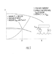
- FIG. 5 a graph illustrating exemplary means for operating the system of the present disclosure at the dividing point between pump speed control for higher flow demand situations and freshwater shunt valve control for lower flow demand situation.
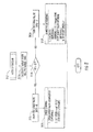
- FIG. 6 is a flow diagram illustrating an exemplary detailed method in accordance with the present disclosure.
- FIG. 7 is a flow diagram illustrating a configuration sub-method of the method shown in FIG. 6 .
- FIG. 8 is a flow diagram illustrating an auto operation sub-method of the method shown in FIG. 6 .
- FIG. 9 is a flow diagram illustrating a teach in sub-method of the method shown in FIG. 6 .
- FIG. 10 is a flow diagram illustrating a startup control sub-method of the method shown in FIG. 6 .
- FIG. 11 is a flow diagram illustrating a backup pump & operation sub-method of the method shown in FIG. 6 .
- FIG. 12 is a graph illustrating the startup control sub-method shown in FIG. 9 .
- FIG. 1 a schematic representation of an exemplary intelligent sea water cooling system 10 (hereinafter “the system 10 ”) is shown.
- the system 10 may be installed onboard any type of seafaring vessel or offshore platform having one or more engines 11 that require cooling. Only a single engine 11 is shown in FIG. 1 , but it will be appreciated by those of ordinary skill in the art the engine 11 may be representative of a plurality of engines or various other loads onboard a vessel or platform that may be coupled to the cooling system 10 .
- the system 10 may include a sea water cooling loop 12 and a fresh water cooling loop 14 that are thermally coupled to one another by a heat exchanger 15 as further described below. Only a single heat exchanger 15 is shown in FIG. 1 , but it is contemplated that the system 10 may alternatively include two or more heat exchangers for providing greater thermal transfer between the sea water cooling loop 12 and the fresh water cooling loop 14 without departing from the present disclosure.
- the sea water cooling loop 12 of the system 10 may include a main pump 16 , a secondary pump 18 , and a backup pump 20 .
- the pumps 16 - 20 may be driven by respective variable frequency drives 22 , 24 , and 26 (hereinafter “VFDs 22 , 24 , and 26 ”).
- VFDs 22 , 24 , and 26 respectively variable frequency drives 22 , 24 , and 26 .
- the pumps 16 - 20 may be centrifugal pumps, but it is contemplated that the system 10 may alternatively or additionally include various other types of fluid pumps.
- the VFDs 22 - 26 may be operatively connected to respective main, secondary, and backup controllers 28 , 30 , and 32 via communications links 40 , 42 , and 44 .
- Various sensors and monitoring devices 35 , 37 , and 39 including, but not limited to, vibration sensors, pressure sensors, bearing temperature sensors, and other possible sensors, may be operatively mounted to the pumps 16 , 18 and 20 and connected to the corresponding controllers 28 , 30 and 32 via the communications links 34 , 36 , and 38 . These sensors may be provided for monitoring the health of the pumps 16 , 18 , and 20 as further described below.
- the controllers 28 - 32 may further be connected to one another by communications link 46 .
- the communication link 46 may be transparent to other networks, providing supervising communication capability.
- the controllers 28 - 32 may be configured to control the operation of the VFDs 22 - 26 (and therefore the operation of the pumps 16 - 20 ) to regulate the flow of sea water to the heat exchanger 15 as further described below.
- the controllers 28 - 32 may be any suitable types of controllers, including, but not limited to, proportional-integral-derivative (PID) controllers and/or a programmable logic controllers (PLCs).
- PID proportional-integral-derivative
- PLCs programmable logic controllers
- the controllers 28 - 32 may include respective memory units and processors (not shown) that may be configured to receive and store data provided by various sensors in the cooling system 10 , to communicate data between controllers and networks outside of the system 10 , and to store and execute software instructions for performing the method steps of the present disclosure as described below.
- the communications links 34 - 46 as well as communications links 81 , 104 and 108 described below, are illustrated as being hard wired connections. It will be appreciated, however, that the communications links 34 - 46 , 91 , 104 and 108 of the system 10 may be embodied by any of a variety of wireless or hard-wired connections.
- the communication links 34 - 46 , 91 , 104 and 108 may be implemented using Wi-Fi, a Bluetooth, PSTN (Public Switched Telephone Network), a satellite network system, a cellular network such as, for example, a GSM (Global System for Mobile Communications) network for SMS and packet voice communication, General Packet Radio Service (GPRS) network for packet data and voice communication, or a wired data network such as, for example, Ethernet/Internet for TCP/IP, VOIP communication, etc.
- GSM Global System for Mobile Communications
- GPRS General Packet Radio Service
- the sea water cooling loop 12 may include various piping and piping system components (“piping”) 50 , 52 , 54 , 56 , 58 , 60 , 62 , 64 , 66 , 68 , 70 for drawing water from the sea 72 , through the pumps 16 - 20 , and for circulating the sea water through the sea water cooling loop 12 , including a seawater side of the heat exchanger 15 , as further described below.
- piping piping and piping system components
- the piping 50 - 70 may be any type of rigid or flexible conduits, pipes, tubes, or ducts that are suitable for conveying water, and may be arranged in any suitable configuration aboard a vessel or platform as may be appropriate for a particular application.
- the sea water cooling loop 12 may further include a discharge valve 89 disposed intermediate the conduits 68 and 70 and connected to the main controller 28 via communications link 91 .
- the discharge valve 89 may be adjustably opened and closed to vary the operational characteristics (e.g., pressure) of the pumps 16 - 20 as further described below.
- the discharge valve is a throttle valve.
- the fresh water cooling loop 14 of the system 10 may be a closed fluid loop that includes a fluid pump 80 and various piping and components 84 , 86 , 88 , 90 , 92 , and 94 for continuously pumping and conveying fresh water through the heat exchanger 15 and the engine 11 for cooling the engine 11 as further described below.
- the fresh water cooling loop 14 may further include a 3-way valve 102 that is connected to the main controller 28 via communications link 104 for controllably allowing a specified quantity of water in the fresh water cooling loop 14 to bypass the heat exchanger 15 as further described below.
- a temperature in the fresh water cooling loop 14 may be measured and monitored by the main controller 28 for facilitating various control operations of the cooling system 10 .
- Such temperature measurement may be performed by a resistance temperature detector 106 (hereinafter “RTD 106 ”) or other temperature measurement device that is operatively connected to the fresh water cooling loop 14 .
- RTD 106 is shown in FIG. 1 as measuring the temperature of the fresh water cooling loop 14 on the inlet side of the engine 11 , but it is contemplated that the RTD 106 may alternatively or additionally measure the temperature of the fresh water cooling loop 14 on the outlet side of the engine 11 .
- the RTD 106 may be connected to the main controller 28 by communications link 108 , or, alternatively, may be an integral, onboard component of the main controller 28 .
- FIG. 2 a flow diagram illustrating a general exemplary method for operating the system 10 in accordance with the present disclosure is shown. The method will be described in conjunction with the schematic representation of the system 10 shown in FIG. 1 . Unless otherwise specified, the described method may be performed wholly or in part by the controllers 28 - 32 , such as through the execution of various software algorithms by the processors thereof.
- the system 10 may be activated, such as by an operator making an appropriate selection in an operator interface (not shown) of the system 10 .
- the main and secondary controllers 28 and 30 may command the VFDs 22 and 24 to begin driving at least one of the pumps 16 and 18 .
- the pumps 16 and 18 may thus begin pumping sea water from the sea 72 , through the piping 52 and 54 , through the pumps 16 and 18 , through the piping 58 - 66 , through the heat exchanger 15 , and finally through the piping 68 and 70 and back to the sea 72 .
- As the sea water flows through the heat exchanger 15 it may cool the fresh water in the fresh water cooling loop 14 that also flows through the heat exchanger 15 .
- the cooled fresh water thereafter flows through and cools the engine 11 .
- the main controller 28 may monitor the temperature of the fresh water in the fresh water cooling loop 14 via the RTD 106 .
- the main controller 28 may thereby determine whether the fresh water is at a desired temperature for providing the engine 11 with appropriate cooling, such as by comparing the monitored temperature to a predefined temperature range.
- the desired temperature level of the freshwater at the discharge of the heat exchanger may be 35 degrees Celsius, and the range of the temperature may be +/ ⁇ 3 degrees Celsius.
- the main controller 28 may, at step 220 of the exemplary method, increase the speed of the VFD 22 and may issue a command to the secondary controller 30 to increase the speed of the VFD 24 .
- the corresponding main and/or secondary pumps 16 and 18 are thereby driven faster, and the flow of sea water through the sea water cooling loop 12 is increased. Greater cooling is thereby provided at the heat exchanger 15 , and the temperature in the fresh water cooling loop 14 is resultantly decreased.
- the main controller 28 may additionally command the 3-way valve 102 to adjust its position, thereby adjusting the amount of fresh water in the fresh water cooling loop 14 through the heat exchanger 15 in order to achieve optimal cooling of the fresh water.
- the main controller 28 may, at step 230 of the exemplary method, decrease the speed of the VFD 22 and may issue a command to the secondary controller 30 to decrease the speed of the VFD 24 .
- the corresponding main and secondary pumps 16 and 18 are thereby driven more slowly, and the flow of sea water through the sea water cooling loop 12 is decreased. Less cooling is thereby provided at the heat exchanger 15 and the temperature in the fresh water cooling loop 14 is resultantly increased.
- the main controller 28 may additionally command the 3-way valve 102 to adjust its position, thereby diverting some or all of the fresh water in the fresh water cooling loop 14 to bypass the heat exchanger 15 in order to further reduce the cooling of the fresh water.
- the pumps 16 , 18 may be required to operate at a speed that is not consistent with the flow required to meet the fresh water temperature target.
- the main controller 28 at step 240 may set a speed and activate valve 102 to assume the set temperature control.
- the centrifugal pump operates at the point in which the system curve crosses the pump curve.
- the hydraulics of the pump within the seawater cooling loop 12 will not allow the pump or pumps to operate in a stable low pressure requiem or have the ability to maintain the precision required by the cooling system solely by speed control.
- the inclusion of a control throttling valve 89 in the seawater discharge line after the heat exchanger 15 allows extended operating range. Addition of this valve 89 can change the system curve, and its position can be adjusted, so as to control the system curve changing the operating point and extending control to a lower speed. This adjustment can enable the pumps 16 , 18 to be operated at a lower speed than would normally be the case while still providing the desired low level of cooling to the fresh water loop 14 . As will be appreciated, this arrangement can extend the operating range to save additional energy.
- the main controller 28 may, at step 240 , decrease the speed of the VFD 22 to drive the main pump 16 at or near a minimum safe operating speed, may command the secondary controller to decrease the speed of the VFD 24 to drive the secondary pump 18 at or near a minimum safe operating speed (or to shut down), and may further command the discharge valve 89 to partially close in order to maintain a required minimum system discharging pressure.
- the discharge valve 89 By partially closing the discharge valve 89 thusly, the flow rate in the sea water cooling loop 12 may be restricted/reduced without further reducing the operational speeds of the pumps 16 and 18 , and the minimum required system discharging pressure can be maintained.
- the pumps 16 and 18 may thereby be operated above their minimum safe operating speeds while achieving a desired low flow rate in the sea water cooling loop 12 .
- the pumps 16 and 18 may be driven only as fast as is necessary to provide a requisite amount of cooling at the heat exchanger 15 .
- the system 10 may therefore be operated much more efficiently and may provide significant fuel savings relative to traditional sea water cooling systems in which sea water pumps are driven at a constant speed regardless of temperature variations. Such improved efficiency is illustrated in the graph shown in FIG. 3 .
- pump power “P” is proportional to the cube of pump speed “n,” while flowrate “Q” is proportional to pump speed “n.”
- Qopt flowrate
- pump power “P” is proportional to the cube of pump speed “n”
- flowrate “Q” is proportional to pump speed “n.”
- the main controller 28 may determine whether the system 10 should be operated in a 2 ⁇ 100% mode or a 2-pump mode in order to achieve a desired efficiency. That is, it may be more efficient in some situations (e.g., if minimal cooling is required) to drive only one of the pumps 16 or 18 and not the other. Alternatively, it may be more efficient and/or necessary to drive both of the pumps 16 and 18 at a low speed.
- the main controller 28 may make such a determination by comparing the operating speeds of the pumps 16 and 18 to predefined “switch points.” “Switch points” may be threshold operating speed values that are used to determine whether the system 10 should switch from 2-pump mode to 2 ⁇ 100% mode or vice versa.
- the main controller 28 may deactivate the secondary pump 18 and run only the main pump 16 .
- the main controller 28 may activate the secondary pump 18 .
- the switch points may be determined based on the actual flow rate“Q” in the system 10 compared to optimal flow range “Qopt.” According to the exemplary curve, when Q/Qopt exceeds 127% under single pump operation, the system can switch to two pump operation to operate most efficiently. Likewise, when Q/Qopt falls below 74% under two pump operation, the system can switch to single pump operation. At the same time, the discharging valve is controlled so that the required minimum system discharging pressure is maintained at all times.
- the main, secondary, and backup controllers 28 , 30 , and 32 may periodically transmit data packets to one another, such as via communications link 46 .
- data packets may include information relating to the critical operational status, or “health,” of each of the controllers 28 - 32 including their respective pumps 16 - 20 and VFDs 22 - 26 . If it is determined that one of the controllers 28 - 32 has ceased to operate properly, or is trending in a direction that would indicate a near or far term malfunction, or if its communications link has malfunctioned or is otherwise inactive, the duties of that controller may, at step 260 of the exemplary method, be reassigned to another one of the controllers.
- the duties of the secondary controller 30 may be reassigned to the back-up controller 32 .
- the duties of the main controller 28 may be reassigned to the secondary controller 30 and the duties of the secondary controller 30 may be reassigned to the back-up controller 32 .
- the system 10 is thereby provided with a level of redundancy that allows to the system 10 carry on with normal operation even after the occurrence of component failures.
- the system 10 may be provided with additional controllers, pumps, and VFDs if additional layers of redundancy are desired.
- the back-up controller will automatically stop its operation of its pump, and will be in stand-by mode for providing future needs for its back-up role.
- the main controller 28 may execute a “teach in” function, such as automatically during each startup operation and/or during its startup from restoration from a previous failure and/or ceased operation, whereby which initial operating parameters of the system can be automatically set without requiring user action.
- the purpose of the “teach in” function is to determine a pump operating speed necessary for ensuring that the system operates at or above a minimum pressure level, such as may be defined by an operator of a vessel.
- one or both operating pumps 16 , 18 may be started with the discharge valve 89 open. Pump speed is then gradually increased until a required minimum system discharging pressure value “Pmin” (Hmin) is reached. Power “P*” and pump speed “n*” are also measured using the pump's associated VFD. These values are used to calculate a value for initial flow “Q*.”
- FIGS. 6-11 a series of flow diagrams illustrating a more detailed exemplary method for operating the system 10 in accordance with the present disclosure will be described. The method will be described in conjunction with the schematic representation of the system 10 shown in FIG. 1 . Unless otherwise specified, the described method may be performed wholly or in part by software algorithms, such as may be executed by one or more of the controllers 28 - 32 .
- the system 10 may be powered on, such as by an operator making an appropriate selection in a user interface (e.g., touchscreen) of one of the controllers 28 or 30 .
- a user interface e.g., touchscreen
- the operator may instead interact with a user interface of the controller 30 in a similar manner.
- the system 10 may initially enter an automatic operation mode.
- the system 10 may present an operator with an option to place the system 10 in a manual operation mode, to turn the system 10 off, or to maintain the automatic operation mode. Such an option may be presented to the operator on a display of the controller 28 .
- the controller 28 may set a VFD operation mode flag to OFF at step 303 .
- the other controllers 30 and 32 may thereby identify that the controller 28 is turned off, and the back-up controller 32 may automatically start-up for joining the operation.
- the controller 28 may set the VFD operation mode flag to MANUAL at step 304 .
- the manual mode may thus provide a back-up function, such as may be necessary if one or more of the controllers 28 - 32 malfunctions and/or automatic system operation is impaired. If the operator selects the automatic operation mode, the controller 28 may set the VFD operation mode flag to AUTOMATIC at step 305 .
- the system 10 may determine whether to operate in a 2 ⁇ 100% mode or a 2-pump mode (as described above in relation to FIG. 4 ). Such a determination may be made by comparing the operating speeds of the pumps 16 and 18 to predefined “switch points.” “Switch points” may be threshold operating speed values that are used to determine whether the system 10 should switch from 2-pump mode to 2 ⁇ 100% mode or vice versa. For example, if the system 10 is operating in 2-pump mode and both of the pumps 16 and 18 are being driven at less than 74% of their maximum operating speeds, it may be determined that the system 10 should switch to 2 ⁇ 100%.
- the system 10 may be determined that the system 10 should switch to 2-pump mode.
- the switch points may be calculated based on known flow rates in the system 10 as illustrated in FIG. 4 .
- the controller 28 may set a pump flag to “1” at step 307 . Conversely, if it was determined in step 306 that the system 10 should operate in 2-pump mode, the controller 28 may set the pump flag to “2” at step 308 .
- the controller 28 may present the operator with an option to perform a configuration of the system 10 . If the operator indicates that he wishes to perform configuration, such as by making an appropriate selection in the user interface of the controller 28 , the controller may, at step 310 , perform the configuration sub-method shown in FIG. 7 . Particularly, the controller 28 may, at step 310 a of the method, check the previously set pump flag (see step 306 in FIG. 6 ) to determine whether the system is operating in 2 ⁇ 100% mode or 2-pump mode. If the system 10 is operating in 2 ⁇ 100% mode, the controller 28 may, at step 310 b of the method, designate itself as the main controller in the system 10 and the controller 30 may be assigned as a back-up controller. Alternatively, if the system 10 is operating in 2-pump mode, the controller 28 may, at steps 310 c and 310 d of the method, present the operator with an option to designate the controller 28 as either the main controller or the secondary controller of the system 10 .
- the controller 28 may, at step 310 e , designate the other controller 30 as the main controller in the system 10 .
- the controller 28 may, at step 310 f , designate the other controller 30 as the secondary controller in the system 10 .
- the third controller 32 will automatically be assigned as a back-up controller.
- the controller 28 may establish a plurality of pump parameters, such as may be provided by a pump manufacturer.
- pump parameters may include a reference speed Nref, a reference efficiency Eff for Q/Qopt in a range from 0%-140%, a reference flow Q for Q/Qopt in a range from 0%-140%, a reference head H for Q/Qopt in a range from 0%-140%, a reference pressure P for Q/Qopt in a range from 0%-140%, speed limits, suction pressure limits, discharge pressure limits, bearing temperature limits, and vibration limits.
- the controller 28 may establish a plurality of system parameters, such as may be provided by a vessel operator.
- system parameters may include a fresh water temperature range, a VFD motor speed range, a minimum pressure level, a fresh water flow, a water heat capacity coefficient, a heat exchanger surface area, a heat transfer coefficient, presence of a 3-way valve, and ambient temperature limits.
- the established pump parameters and system parameters described above may be copied to the other controller 30 (i.e., if the system 10 is operating in 2-pump mode), such as by transmission through the communications link 46 .
- the controller 28 may, at step 311 of the method, determine whether the system 10 is running under automation operation (described above). If the controller 28 determines that the system 10 is currently running under automatic operation, the controller may, at step 312 , perform the auto operation and control sub-method shown in FIG. 8 . Particularly, the controller 28 may, at step 312 a , calculate a target flow rate QT for the flow of sea water in the sea water cooling loop 12 .
- QT may be calculated as the result of PI controller, PI(Ttarget-TFW), wherein Ttarget is a desired temperature level of the fresh water in the fresh water cooling loop 14 and TFW is the actual temperature of the fresh water in the fresh water cooling loop 14 as measured, for example, by RTD 106 .
- the controller 28 may, at step 312 d , operate the 3-way valve 102 to assume a partially open position to cause a certain amount of freshwater to bypass the heat exchanger 15 .
- the controller 28 may further calculate an amount which the 3-way shunt valve 102 should be opened, such as may be given by the result of PI controller, PI(Ttarget-TFW), and may command the 3-way shunt 102 valve to open by such an amount.
- the controller 28 may further maintain the minimum speed n* of the pumps 16 and 18 (or only the pump 16 if the system 10 is in 2 ⁇ 100% mode).
- the controller 28 may, at step 313 of the method, determine whether the system is in AUTO mode (described above). If so, the controller 28 may perform a startup process, the first step of which is to execute, at step 314 , the “teach in” sub-method shown in FIG. 9 . Particularly, the controller may, at step 314 a of the method, increase the speeds of the pumps 16 and 18 (or only the pump 16 if the system 10 is in 2 ⁇ 100% mode) until a required minimum system discharging pressure level Pmin is reached in the sea water cooling loop 12 .
- the controller 28 may, at step 314 b of the method, read a “teach in” speed n* and a teach in pressure P* from the VFDs 22 and 24 (or only the VFD 22 if the system 10 is in 2 ⁇ 100% mode), calculate a teach in flow Q* and a new minimum pressure level Pmin, and may store Q*, P*, n*, and Pmin.
- Q* can be calculated by using pump head-and-flow curve, which the pump manufacturer can provide.
- the controller 28 may, at step 315 of the method, perform the “startup control” sub-method shown in FIG. 10 .
- the controller 28 may, at step 315 a , increase the speeds of the pumps 16 and 18 (or only the pump 16 if the system 10 is in 2 ⁇ 100% mode) to the teach-in speed level n* (also the minimum speed for the system generates the required minimum system discharging pressure).
- the controller 28 may then proceed to perform the auto operation sub-method of step 312 described above in relation to FIG. 8 .
- the controller 28 may, at step 316 , determine whether there are any alarms in the system 10 (e.g., with predefined time delays to ensure that the alarms are not false alarms produced by transient electrical “noise”). For example, the controller 28 may determine whether either of the pumps 16 or 18 (or only the pump 16 if the system 10 is in 2 ⁇ 100% mode) is operating outside of the pump parameters established in the configuration sub-method described above, such as may be determined from the sensors 35 , 37 , and 39 .
- the controller 28 may, at step 317 of the method ( FIG. 6 ), determine whether the backup pump 20 is ready for operation. If it is determined that the backup pump 20 is ready for operation, the controller 28 may, at step 318 , perform the backup pump & operation sub-method shown in FIG. 11 . Particularly, the controller 28 may, at step 318 a , command the controller 32 of the backup pump 20 to increase the speed of the backup pump 20 to the same speed level of the VFD 22 . Finally, the controller 28 may, at step 319 of the method, stop operation of the faulty pump 16 or 18 if such operation had not ceased previously.
- the controller may, at step 320 of the method, use the sensors 35 , 37 , and 39 to measure a sea water temperature TSW, an ambient temperature Tamb, a fresh water temperature TFW, a pump vibration V, a pump suction pressure PS, a pump discharge pressure PD, and a pump bearing temperature T.
- the controller 28 may read from the VFDs 22 and 24 (or only the VFD 22 if the system 10 is in 2 ⁇ 100% mode) an actual speed nACT, a power consumption P or torque or current and voltage.
- the controller 28 may display any warnings related to operation of the pumps 16 and 18 or the system 10 , and the entire method described above may be repeated starting at step 301 .
- an element or step recited in the singular and proceeded with the word “a” or “an” should be understood as not excluding plural elements or steps, unless such exclusion is explicitly recited.
- references to “one embodiment” of the present invention are not intended to be interpreted as excluding the existence of additional embodiments that also incorporate the recited features.
- Such a computer system may include a computer, an input device, a display unit and an interface, for example, for accessing the Internet.
- the computer may include a microprocessor.
- the microprocessor may be connected to a communication bus.
- the computer may also include memories.
- the memories may include Random Access Memory (RAM) and Read Only Memory (ROM).
- the computer system further may include a storage device, which may be a hard disk drive or a removable storage drive such as a floppy disk drive, optical disk drive, and the like.
- the storage device may also be other similar means for loading computer programs or other instructions into the computer system.
- the term “computer” may include any processor-based or microprocessor-based system including systems using microcontrollers, reduced instruction set circuits (RISCs), application specific integrated circuits (ASICs), logic circuits, and any other circuit or processor capable of executing the functions described herein.
- RISCs reduced instruction set circuits
- ASICs application specific integrated circuits
- the above examples are exemplary only, and are thus not intended to limit in any way the definition and/or meaning of the term “computer.”
- the computer system executes a set of instructions that are stored in one or more storage elements, in order to process input data.
- the storage elements may also store data or other information as desired or needed.
- the storage element may be in the form of an information source or a physical memory element within the processing machine.
- the set of instructions may include various commands that instruct the computer as a processing machine to perform specific operations such as the methods and processes of the various embodiments of the invention.
- the set of instructions may be in the form of a software program.
- the software may be in various forms such as system software or application software. Further, the software may be in the form of a collection of separate programs, a program module within a larger program or a portion of a program module.
- the software also may include modular programming in the form of object-oriented programming.
- the processing of input data by the processing machine may be in response to user commands, or in response to results of previous processing, or in response to a request made by another processing machine.
- the term “software” includes any computer program stored in memory for execution by a computer, such memory including RAM memory, ROM memory, EPROM memory, EEPROM memory, and non-volatile RAM (NVRAM) memory.
- RAM random access memory
- ROM read-only memory
- EPROM electrically erasable programmable read-only memory
- EEPROM electrically erasable programmable read-only memory
- NVRAM non-volatile RAM
Landscapes
- Engineering & Computer Science (AREA)
- Chemical & Material Sciences (AREA)
- Combustion & Propulsion (AREA)
- Mechanical Engineering (AREA)
- Ocean & Marine Engineering (AREA)
- General Engineering & Computer Science (AREA)
- Feedback Control In General (AREA)
- Control Of Non-Positive-Displacement Pumps (AREA)
Priority Applications (1)
| Application Number | Priority Date | Filing Date | Title |
|---|---|---|---|
| US14/785,549 US9797294B2 (en) | 2013-04-19 | 2014-04-09 | Intelligent sea water cooling system |
Applications Claiming Priority (3)
| Application Number | Priority Date | Filing Date | Title |
|---|---|---|---|
| US201361813822P | 2013-04-19 | 2013-04-19 | |
| PCT/US2014/033422 WO2014172153A1 (fr) | 2013-04-19 | 2014-04-09 | Système de refroidissement intelligent à eau de mer |
| US14/785,549 US9797294B2 (en) | 2013-04-19 | 2014-04-09 | Intelligent sea water cooling system |
Publications (2)
| Publication Number | Publication Date |
|---|---|
| US20160076434A1 US20160076434A1 (en) | 2016-03-17 |
| US9797294B2 true US9797294B2 (en) | 2017-10-24 |
Family
ID=51731764
Family Applications (1)
| Application Number | Title | Priority Date | Filing Date |
|---|---|---|---|
| US14/785,549 Expired - Fee Related US9797294B2 (en) | 2013-04-19 | 2014-04-09 | Intelligent sea water cooling system |
Country Status (8)
| Country | Link |
|---|---|
| US (1) | US9797294B2 (fr) |
| EP (1) | EP2986500B1 (fr) |
| JP (1) | JP6272456B2 (fr) |
| KR (2) | KR102046516B1 (fr) |
| CN (1) | CN105073576A (fr) |
| CA (1) | CA2907590C (fr) |
| SG (1) | SG11201507197RA (fr) |
| WO (1) | WO2014172153A1 (fr) |
Cited By (3)
| Publication number | Priority date | Publication date | Assignee | Title |
|---|---|---|---|---|
| US11034427B2 (en) * | 2016-09-27 | 2021-06-15 | Indmar Products Company Inc. | Heat exchange systems for engine-powered watercraft and methods of using same |
| USD1073892S1 (en) | 2021-01-26 | 2025-05-06 | Dometic Sweden Ab | Air conditioning housing |
| US12565081B2 (en) | 2021-01-26 | 2026-03-03 | Dometic Sweden Ab | Air conditioning system for a vehicle |
Families Citing this family (11)
| Publication number | Priority date | Publication date | Assignee | Title |
|---|---|---|---|---|
| JP6349463B2 (ja) * | 2015-02-13 | 2018-06-27 | アイエムオー・インダストリーズ・インコーポレーテッド | 知能型海水冷却システム及び方法 |
| DE102015218889B3 (de) | 2015-09-30 | 2017-03-30 | Siemens Aktiengesellschaft | Antrieb für ein wassergebundenes Fortbewegungsmittel |
| DE102015218896B4 (de) * | 2015-09-30 | 2017-05-04 | Siemens Aktiengesellschaft | Antrieb für ein wassergebundenes Fortbewegungsmittel |
| DE102016213787A1 (de) * | 2016-07-27 | 2018-02-01 | Man Diesel & Turbo Se | Verfahren zum Betreiben eines Kühlsystems eines Schiffs |
| JP6788440B2 (ja) * | 2016-09-06 | 2020-11-25 | 川崎重工業株式会社 | 船舶の冷却システム |
| CN108750064B (zh) * | 2018-05-14 | 2023-09-08 | 广州航海学院 | 一种船舶中央冷却水多段比值控制系统及方法 |
| CN111483583B (zh) * | 2020-04-14 | 2021-07-13 | 中国舰船研究设计中心 | 一种二回路冷却水系统变工况调节方法 |
| US20220154720A1 (en) * | 2020-11-19 | 2022-05-19 | Brunswick Corporation | Bilge pump systems |
| CN112572752A (zh) * | 2020-11-27 | 2021-03-30 | 沪东中华造船(集团)有限公司 | 一种船用海水冷却泵变频节能方法 |
| CN114030582B (zh) * | 2021-10-19 | 2024-01-26 | 中国舰船研究设计中心 | 一种集成式机舱海水冷却系统 |
| EP4720483A1 (fr) | 2023-06-02 | 2026-04-08 | West Maritime AS | Système et procédé de commande de système de refroidissement de navire |
Citations (18)
| Publication number | Priority date | Publication date | Assignee | Title |
|---|---|---|---|---|
| FR1237044A (fr) | 1958-10-09 | 1960-07-22 | Sueddeutsche Kuehler Behr | Perfectionnements apportés aux dispositifs de réglage de la température du circuit d'eau de refroidissement des moteurs à combustion interne, plus spécialement des moteurs pour bateaux |
| DD217274A1 (de) | 1983-06-08 | 1985-01-09 | Seefahrt Inghochschule | Verfahren zur verminderung der pumpengesamtantriebsleistung in mehrkreisfluessigkeitskuehlsystemen, insbesondere fuer verbrennungskraftmaschinen |
| US4726325A (en) * | 1986-03-28 | 1988-02-23 | Aisin Seiki Kabushki Kaisha | Cooling system controller for internal combustion engines |
| US5004042A (en) | 1989-10-02 | 1991-04-02 | Brunswick Corporation | Closed loop cooling for a marine engine |
| JPH08100772A (ja) | 1994-09-30 | 1996-04-16 | Hitachi Ltd | ポンプ装置 |
| US5599217A (en) | 1995-11-08 | 1997-02-04 | Ferrante; Joseph | Rapid cooling system for liquid-cooled engines |
| JPH0979036A (ja) | 1995-09-08 | 1997-03-25 | Hitachi Zosen Corp | 船舶における冷却運転方法および冷却設備 |
| JP2000145651A (ja) | 1998-11-06 | 2000-05-26 | Kubota Corp | 複数台ポンプの運転制御システム |
| US6739290B2 (en) | 2001-03-06 | 2004-05-25 | Calsonic Kansei Corporation | Cooling system for water-cooled internal combustion engine and control method applicable to cooling system therefor |
| JP2004225672A (ja) | 2003-01-27 | 2004-08-12 | Ebara Densan Ltd | 回転機械の運転制御装置 |
| US6955141B2 (en) | 2003-08-06 | 2005-10-18 | General Motors Corporation | Engine cooling system |
| KR20100080566A (ko) | 2008-05-12 | 2010-07-08 | 미츠비시 쥬고교 가부시키가이샤 | 냉각 해수 이송 펌프의 회전수 제어 장치 |
| JP2011122771A (ja) | 2009-12-11 | 2011-06-23 | Nyk Trading Corp | 熱負荷冷却装置および熱負荷冷却装置用制御装置 |
| US20120097118A1 (en) | 2009-07-07 | 2012-04-26 | Malmgren Bjoern | Device and method for improving performance of a motor vehicle |
| JP2012122371A (ja) | 2010-12-07 | 2012-06-28 | Ihi Marine United Inc | 冷却システム及び冷却方法 |
| US8602117B2 (en) * | 2008-09-29 | 2013-12-10 | Electronic Power Design | System and method for supplying sea water during fire fighting operations on a naval vessel |
| JP2014006910A (ja) * | 2002-09-24 | 2014-01-16 | Ricoh Co Ltd | 管理仲介装置、画像形成装置、管理仲介プログラム及び管理仲介プログラムを記録した記録媒体 |
| JP2014046910A (ja) * | 2012-08-29 | 2014-03-17 | Koji Kita | ディーゼル機関の主冷却システム |
Family Cites Families (3)
| Publication number | Priority date | Publication date | Assignee | Title |
|---|---|---|---|---|
| JP3117442B2 (ja) * | 1988-07-07 | 2000-12-11 | 株式会社日立製作所 | 車両制御装置 |
| CN101087715A (zh) * | 2004-10-25 | 2007-12-12 | 斯沃德船舶科技公司 | 具有增强马力的舷外喷射驱动船用推进装置 |
| JP4790061B2 (ja) * | 2006-04-28 | 2011-10-12 | スカニア シーブイ アクチボラグ | 車両の冷却ファン装置 |
-
2014
- 2014-04-09 CA CA2907590A patent/CA2907590C/fr not_active Expired - Fee Related
- 2014-04-09 CN CN201480017807.4A patent/CN105073576A/zh active Pending
- 2014-04-09 EP EP14784652.1A patent/EP2986500B1/fr not_active Not-in-force
- 2014-04-09 SG SG11201507197RA patent/SG11201507197RA/en unknown
- 2014-04-09 KR KR1020177017423A patent/KR102046516B1/ko not_active Expired - Fee Related
- 2014-04-09 JP JP2016507626A patent/JP6272456B2/ja not_active Expired - Fee Related
- 2014-04-09 US US14/785,549 patent/US9797294B2/en not_active Expired - Fee Related
- 2014-04-09 WO PCT/US2014/033422 patent/WO2014172153A1/fr not_active Ceased
- 2014-04-09 KR KR1020157029190A patent/KR20150129003A/ko not_active Ceased
Patent Citations (18)
| Publication number | Priority date | Publication date | Assignee | Title |
|---|---|---|---|---|
| FR1237044A (fr) | 1958-10-09 | 1960-07-22 | Sueddeutsche Kuehler Behr | Perfectionnements apportés aux dispositifs de réglage de la température du circuit d'eau de refroidissement des moteurs à combustion interne, plus spécialement des moteurs pour bateaux |
| DD217274A1 (de) | 1983-06-08 | 1985-01-09 | Seefahrt Inghochschule | Verfahren zur verminderung der pumpengesamtantriebsleistung in mehrkreisfluessigkeitskuehlsystemen, insbesondere fuer verbrennungskraftmaschinen |
| US4726325A (en) * | 1986-03-28 | 1988-02-23 | Aisin Seiki Kabushki Kaisha | Cooling system controller for internal combustion engines |
| US5004042A (en) | 1989-10-02 | 1991-04-02 | Brunswick Corporation | Closed loop cooling for a marine engine |
| JPH08100772A (ja) | 1994-09-30 | 1996-04-16 | Hitachi Ltd | ポンプ装置 |
| JPH0979036A (ja) | 1995-09-08 | 1997-03-25 | Hitachi Zosen Corp | 船舶における冷却運転方法および冷却設備 |
| US5599217A (en) | 1995-11-08 | 1997-02-04 | Ferrante; Joseph | Rapid cooling system for liquid-cooled engines |
| JP2000145651A (ja) | 1998-11-06 | 2000-05-26 | Kubota Corp | 複数台ポンプの運転制御システム |
| US6739290B2 (en) | 2001-03-06 | 2004-05-25 | Calsonic Kansei Corporation | Cooling system for water-cooled internal combustion engine and control method applicable to cooling system therefor |
| JP2014006910A (ja) * | 2002-09-24 | 2014-01-16 | Ricoh Co Ltd | 管理仲介装置、画像形成装置、管理仲介プログラム及び管理仲介プログラムを記録した記録媒体 |
| JP2004225672A (ja) | 2003-01-27 | 2004-08-12 | Ebara Densan Ltd | 回転機械の運転制御装置 |
| US6955141B2 (en) | 2003-08-06 | 2005-10-18 | General Motors Corporation | Engine cooling system |
| KR20100080566A (ko) | 2008-05-12 | 2010-07-08 | 미츠비시 쥬고교 가부시키가이샤 | 냉각 해수 이송 펌프의 회전수 제어 장치 |
| US8602117B2 (en) * | 2008-09-29 | 2013-12-10 | Electronic Power Design | System and method for supplying sea water during fire fighting operations on a naval vessel |
| US20120097118A1 (en) | 2009-07-07 | 2012-04-26 | Malmgren Bjoern | Device and method for improving performance of a motor vehicle |
| JP2011122771A (ja) | 2009-12-11 | 2011-06-23 | Nyk Trading Corp | 熱負荷冷却装置および熱負荷冷却装置用制御装置 |
| JP2012122371A (ja) | 2010-12-07 | 2012-06-28 | Ihi Marine United Inc | 冷却システム及び冷却方法 |
| JP2014046910A (ja) * | 2012-08-29 | 2014-03-17 | Koji Kita | ディーゼル機関の主冷却システム |
Non-Patent Citations (2)
| Title |
|---|
| International Search Report dated Aug. 27, 2014 for PCT Application PCT/US2014/033422 filed Apr. 9, 2014. |
| Supplemental European Search Report mailed Dec. 6, 2016 for corresponding European Patent Application 14784652. |
Cited By (3)
| Publication number | Priority date | Publication date | Assignee | Title |
|---|---|---|---|---|
| US11034427B2 (en) * | 2016-09-27 | 2021-06-15 | Indmar Products Company Inc. | Heat exchange systems for engine-powered watercraft and methods of using same |
| USD1073892S1 (en) | 2021-01-26 | 2025-05-06 | Dometic Sweden Ab | Air conditioning housing |
| US12565081B2 (en) | 2021-01-26 | 2026-03-03 | Dometic Sweden Ab | Air conditioning system for a vehicle |
Also Published As
| Publication number | Publication date |
|---|---|
| WO2014172153A1 (fr) | 2014-10-23 |
| JP2016520471A (ja) | 2016-07-14 |
| KR102046516B1 (ko) | 2019-11-19 |
| EP2986500A4 (fr) | 2017-01-18 |
| CN105073576A (zh) | 2015-11-18 |
| KR20170076810A (ko) | 2017-07-04 |
| JP6272456B2 (ja) | 2018-01-31 |
| US20160076434A1 (en) | 2016-03-17 |
| CA2907590A1 (fr) | 2014-10-23 |
| EP2986500B1 (fr) | 2020-05-27 |
| EP2986500A1 (fr) | 2016-02-24 |
| KR20150129003A (ko) | 2015-11-18 |
| CA2907590C (fr) | 2017-10-31 |
| SG11201507197RA (en) | 2015-10-29 |
Similar Documents
| Publication | Publication Date | Title |
|---|---|---|
| US9797294B2 (en) | Intelligent sea water cooling system | |
| US10583908B2 (en) | Intelligent sea water cooling system | |
| US10344662B2 (en) | Intelligent seawater cooling system | |
| US10400658B2 (en) | Intelligent sea water cooling system and method |
Legal Events
| Date | Code | Title | Description |
|---|---|---|---|
| AS | Assignment |
Owner name: IMO INDUSTRIES INC., NEW JERSEY Free format text: ASSIGNMENT OF ASSIGNORS INTEREST;ASSIGNORS:YIN, DAN;MCKINSTRY, DAVID;BRAUN, EDWIN;AND OTHERS;SIGNING DATES FROM 20130424 TO 20130513;REEL/FRAME:043485/0397 |
|
| STCF | Information on status: patent grant |
Free format text: PATENTED CASE |
|
| AS | Assignment |
Owner name: CIRCOR PUMPS NORTH AMERICA, LLC, NORTH CAROLINA Free format text: ASSIGNMENT OF ASSIGNORS INTEREST;ASSIGNOR:IMO INDUSTRIES, INC.;REEL/FRAME:044908/0980 Effective date: 20171211 |
|
| FEPP | Fee payment procedure |
Free format text: MAINTENANCE FEE REMINDER MAILED (ORIGINAL EVENT CODE: REM.); ENTITY STATUS OF PATENT OWNER: LARGE ENTITY |
|
| LAPS | Lapse for failure to pay maintenance fees |
Free format text: PATENT EXPIRED FOR FAILURE TO PAY MAINTENANCE FEES (ORIGINAL EVENT CODE: EXP.); ENTITY STATUS OF PATENT OWNER: LARGE ENTITY |
|
| STCH | Information on status: patent discontinuation |
Free format text: PATENT EXPIRED DUE TO NONPAYMENT OF MAINTENANCE FEES UNDER 37 CFR 1.362 |
|
| FP | Lapsed due to failure to pay maintenance fee |
Effective date: 20211024 |