US9878183B2 - Surgical operation system - Google Patents
Surgical operation system Download PDFInfo
- Publication number
- US9878183B2 US9878183B2 US13/791,933 US201313791933A US9878183B2 US 9878183 B2 US9878183 B2 US 9878183B2 US 201313791933 A US201313791933 A US 201313791933A US 9878183 B2 US9878183 B2 US 9878183B2
- Authority
- US
- United States
- Prior art keywords
- signal
- section
- frequency
- output
- operation system
- Prior art date
- Legal status (The legal status is an assumption and is not a legal conclusion. Google has not performed a legal analysis and makes no representation as to the accuracy of the status listed.)
- Active, expires
Links
Images




Classifications
-
- A—HUMAN NECESSITIES
- A61—MEDICAL OR VETERINARY SCIENCE; HYGIENE
- A61N—ELECTROTHERAPY; MAGNETOTHERAPY; RADIATION THERAPY; ULTRASOUND THERAPY
- A61N7/00—Ultrasound therapy
-
- A—HUMAN NECESSITIES
- A61—MEDICAL OR VETERINARY SCIENCE; HYGIENE
- A61B—DIAGNOSIS; SURGERY; IDENTIFICATION
- A61B17/00—Surgical instruments, devices or methods
- A61B17/32—Surgical cutting instruments
- A61B17/320068—Surgical cutting instruments using mechanical vibrations, e.g. ultrasonic
-
- A—HUMAN NECESSITIES
- A61—MEDICAL OR VETERINARY SCIENCE; HYGIENE
- A61B—DIAGNOSIS; SURGERY; IDENTIFICATION
- A61B18/00—Surgical instruments, devices or methods for transferring non-mechanical forms of energy to or from the body
- A61B18/04—Surgical instruments, devices or methods for transferring non-mechanical forms of energy to or from the body by heating
- A61B18/12—Surgical instruments, devices or methods for transferring non-mechanical forms of energy to or from the body by heating by passing a current through the tissue to be heated, e.g. high-frequency current
- A61B18/14—Probes or electrodes therefor
- A61B18/1402—Probes for open surgery
-
- A—HUMAN NECESSITIES
- A61—MEDICAL OR VETERINARY SCIENCE; HYGIENE
- A61B—DIAGNOSIS; SURGERY; IDENTIFICATION
- A61B18/00—Surgical instruments, devices or methods for transferring non-mechanical forms of energy to or from the body
- A61B18/04—Surgical instruments, devices or methods for transferring non-mechanical forms of energy to or from the body by heating
- A61B18/12—Surgical instruments, devices or methods for transferring non-mechanical forms of energy to or from the body by heating by passing a current through the tissue to be heated, e.g. high-frequency current
- A61B18/1206—Generators therefor
-
- A—HUMAN NECESSITIES
- A61—MEDICAL OR VETERINARY SCIENCE; HYGIENE
- A61B—DIAGNOSIS; SURGERY; IDENTIFICATION
- A61B17/00—Surgical instruments, devices or methods
- A61B17/32—Surgical cutting instruments
- A61B17/320068—Surgical cutting instruments using mechanical vibrations, e.g. ultrasonic
- A61B2017/320069—Surgical cutting instruments using mechanical vibrations, e.g. ultrasonic for ablating tissue
-
- A—HUMAN NECESSITIES
- A61—MEDICAL OR VETERINARY SCIENCE; HYGIENE
- A61B—DIAGNOSIS; SURGERY; IDENTIFICATION
- A61B17/00—Surgical instruments, devices or methods
- A61B17/32—Surgical cutting instruments
- A61B17/320068—Surgical cutting instruments using mechanical vibrations, e.g. ultrasonic
- A61B2017/320082—Surgical cutting instruments using mechanical vibrations, e.g. ultrasonic for incising tissue
-
- A—HUMAN NECESSITIES
- A61—MEDICAL OR VETERINARY SCIENCE; HYGIENE
- A61B—DIAGNOSIS; SURGERY; IDENTIFICATION
- A61B18/00—Surgical instruments, devices or methods for transferring non-mechanical forms of energy to or from the body
- A61B2018/00636—Sensing and controlling the application of energy
- A61B2018/00773—Sensed parameters
- A61B2018/00845—Frequency
-
- A—HUMAN NECESSITIES
- A61—MEDICAL OR VETERINARY SCIENCE; HYGIENE
- A61B—DIAGNOSIS; SURGERY; IDENTIFICATION
- A61B18/00—Surgical instruments, devices or methods for transferring non-mechanical forms of energy to or from the body
- A61B2018/00636—Sensing and controlling the application of energy
- A61B2018/00773—Sensed parameters
- A61B2018/00869—Phase
-
- A—HUMAN NECESSITIES
- A61—MEDICAL OR VETERINARY SCIENCE; HYGIENE
- A61B—DIAGNOSIS; SURGERY; IDENTIFICATION
- A61B18/00—Surgical instruments, devices or methods for transferring non-mechanical forms of energy to or from the body
- A61B2018/0091—Handpieces of the surgical instrument or device
- A61B2018/00916—Handpieces of the surgical instrument or device with means for switching or controlling the main function of the instrument or device
- A61B2018/00928—Handpieces of the surgical instrument or device with means for switching or controlling the main function of the instrument or device by sending a signal to an external energy source
-
- A—HUMAN NECESSITIES
- A61—MEDICAL OR VETERINARY SCIENCE; HYGIENE
- A61B—DIAGNOSIS; SURGERY; IDENTIFICATION
- A61B90/00—Instruments, implements or accessories specially adapted for surgery or diagnosis and not covered by any of the groups A61B1/00 - A61B50/00, e.g. for luxation treatment or for protecting wound edges
- A61B90/06—Measuring instruments not otherwise provided for
- A61B2090/064—Measuring instruments not otherwise provided for for measuring force, pressure or mechanical tension
- A61B2090/065—Measuring instruments not otherwise provided for for measuring force, pressure or mechanical tension for measuring contact or contact pressure
Definitions
- the present invention relates to a surgical operation system including a handpiece to which ultrasound energy and high-frequency energy are simultaneously applied.
- a monopolar type handpiece using a high-frequency current is used when cutting or coagulation of living tissue is performed.
- a cutting mode in which cutting is performed, and a coagulation mode in which coagulation is performed are switched by a waveform of the high-frequency current which is applied to a treatment section 9 of the handpiece.
- a high-frequency current (high-frequency energy) of a continuous waveform is applied, and living tissue is transpired by large heat generation.
- a high-frequency current of an interrupted wave (burst wave) is applied, and thereby living tissue is kept at a temperature at which protein and the like are coagulated.
- a blend mode in which a high-frequency current of a current waveform with the continuous waveform and the burst waveform being blended, bleeding can be stopped while living tissue is cut.
- Japanese Patent Application Laid-Open Publication No. 2002-306507 discloses that living tissue is prevented from being burnt onto the treatment section 9 by application of not only a high-frequency current but also ultrasound vibration to the treatment section 9 .
- Japanese Patent Application Laid-Open Publication No. 2010-5370 discloses a surgical operation system which detects ultrasound impedance corresponding to the ultrasound vibration of the treatment section 9 to which a high-frequency current and ultrasound vibration are applied, and controls the high-frequency current.
- the effect of the conventional surgical operation system including the handpiece to which a high-frequency current and ultrasound vibration are applied is only simple addition of the effect obtained by application of only the high-frequency current and the effect obtained by application of only the ultrasound vibration.
- a surgical operation system of an embodiment includes a drive signal output section that outputs a drive signal, a high-frequency signal output section that outputs a high-frequency signal, a probe having a treatment section with the high-frequency signal being applied thereto, that vibrates by ultrasound that an ultrasound transducer generates by the drive signal, and performs a bleeding stopping process while making an incision line in a pressing direction, when the probe is pressed against a parenchyma organ by a synergetic effect of the drive signal and the high-frequency signal, a counter electrode plate that forms a return circuit of the high-frequency signal, a high-frequency signal main control section that performs feedback control of the high-frequency signal output section, based on the high-frequency signal, a drive signal main control section that performs feedback control of the drive signal output section, based on the drive signal, a high-frequency signal auxiliary control section that controls the high-frequency signal output section to stop output of the high-frequency signal based on the drive signal, and has a response time shorter than that of the high-
- a surgical operation system of another embodiment includes a treatment section that is a treatment section that simultaneously performs a high-frequency treatment and an ultrasound treatment on tissue, and performs a bleeding stopping process while making an incision line on the tissue, a drive signal output section that outputs a drive signal for the ultrasound treatment to the treatment section, a drive signal detection section that detects a parameter of the drive signal which the drive signal output section outputs, a drive signal main control section that performs feedback control of the drive signal output section based on the parameter which is detected in the drive signal detection section, a high-frequency signal output section that outputs a high-frequency signal for the high-frequency treatment to the treatment section, a high-frequency signal detection section that detects a parameter of the high-frequency signal which the high-frequency signal output section outputs, a drive signal main control section that performs feedback control of the high-frequency signal output section based on the parameter which is detected in the high-frequency signal detection section, a high-frequency signal auxiliary control section that determines whether or not the treatment section separates from the tissue
- FIG. 1 is a perspective view showing an entire configuration of a surgical operation system of a first embodiment
- FIG. 2 is a sectional view showing an internal configuration of a handpiece of the surgical operation system of the first embodiment
- FIG. 3 is a configuration diagram showing a configuration of a surgical operation system of the first embodiment
- FIG. 4A is an explanatory diagram for explaining a high-frequency signal of a cutting waveform
- FIG. 4B is an explanatory diagram for explaining a high-frequency signal of a coagulation waveform
- FIG. 5 is a configuration diagram showing a configuration of a signal detection section of the surgical operation system of the first embodiment
- FIG. 6 is a perspective view for explaining processing of making an incision line according to the surgical operation system of the first embodiment
- FIG. 7A is a schematic sectional view of a treatment section for explaining a treatment in a case of only HV energy being applied;
- FIG. 7B is a schematic sectional view of the treatment section for explaining a treatment in a case of the HV energy and US energy being applied;
- FIG. 8 is a flowchart for explaining a flow of processing of the surgical operation system of the first embodiment
- FIG. 9 is a frequency spectrum diagram for explaining signals of the surgical operation system of the first embodiment.
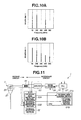
- FIG. 10A is a frequency spectrum diagram for explaining the signal of the surgical operation system of the first embodiment
- FIG. 10B is a frequency spectrum diagram for explaining the signal of the surgical operation system of the first embodiment
- FIG. 11 is a configuration diagram for explaining a configuration example of the surgical operation system of the first embodiment
- FIG. 12 is a graph showing one example of an influence that application of a load to the treatment section exerts on a phase difference of a current and a voltage, in the surgical operation system of the first embodiment
- FIG. 13 is a configuration diagram showing a configuration of a surgical operation system of a modification of the first embodiment
- FIG. 14 is a configuration diagram showing a configuration of a surgical operation system of a second embodiment
- FIG. 15 is a configuration diagram showing a configuration of a signal detection section of the surgical operation system of the second embodiment
- FIG. 16 is a flowchart for explaining a flow of processing of the surgical operation system of the second embodiment
- FIG. 17 is a configuration diagram showing a configuration of a surgical operation system of a modification of the second embodiment
- FIG. 18 is a configuration diagram showing a configuration of a surgical operation system of a third embodiment
- FIG. 19 is a flowchart for explaining a flow of processing of the surgical operation system of the third embodiment.
- FIG. 20 is a configuration diagram showing a configuration of a surgical operation system of a modification of the third embodiment.
- the surgical operation system 1 includes a handpiece 2 , an ultrasound transducer drive signal generating apparatus (hereinafter, called “US apparatus”) 5 , a high-frequency current signal generating apparatus (hereinafter, called “HV apparatus”) 6 , and a counter electrode plate 3 as a recovery section.
- US apparatus ultrasound transducer drive signal generating apparatus
- HV apparatus high-frequency current signal generating apparatus
- counter electrode plate 3 a counter electrode plate 3 as a recovery section.
- the US apparatus 5 and the HV apparatus 6 may be a signal generating apparatus 10 in which the US apparatus 5 and the HV apparatus 6 are housed in one casing and share some functions.
- the monopolar type handpiece 2 is a surgical treatment instrument having a treatment section 9 at a distal end.
- the US apparatus 5 generates a drive signal (hereinafter, called “US signal”) that drives an ultrasound transducer 23 (see FIG. 2 ) contained in the handpiece 2 .
- the HV apparatus 6 supplies a high-frequency signal (hereinafter, called “HV signal”) to the handpiece 2 .
- the counter electrode plate 3 that is the recovery section is disposed to be in contact with a hip or the like of a patient in a large area, and forms a return circuit of the HV signal.
- the handpiece 2 has a grasping portion 7 for a surgeon to grasp, a shaft portion 8 that protrudes forward from the grasping portion 7 , and a treatment section 9 placed at a distal end of the shaft portion 8 .
- a selection switch 11 11 a , 11 b , 11 c ) for performing selection or the like of a treatment that is performed with the treatment section 9 is placed.
- a US cable 13 , a hand switch cable 14 , and an HV cable 15 are extended.
- the US cable 13 and the hand switch cable 14 connectors at end portions thereof are detachably connected to the US apparatus 5 .
- a connector at an end portion thereof is detachably connected to the HV apparatus 6 .
- a connector of an end portion of a counter electrode plate cable 16 that is connected to the counter electrode plate 3 is also detachably connected.
- the US apparatus 5 and the HV apparatus 6 perform transmission and reception of signals via a communication cable 17 which is connected thereto. Further, the US apparatus 5 and the HV apparatus 6 respectively have front panels 18 and 19 for performing display and operation input.
- the US apparatus 5 and the HV apparatus 6 may be operable by foot switches or the like.
- a housing portion is configured by a substantially cylindrical main case 21 that configures the grasping portion 7 , and a secondary case 22 connected to an end portion thereof.
- the ultrasound transducer (US transducer) 23 connected to the US cable 13 is disposed inside the main case 21 .
- the ultrasound transducer 23 includes a plurality of ring-shaped electrostrictive elements 24 that are fastened by a bolt 25 and a nut 26 .
- the ultrasound transducer 23 performs ultrasound vibration.
- the ultrasound vibration is transmitted to the treatment section 9 through the shaft portion 8 that is configured by a horn 27 connected to a front end of the ultrasound transducer 23 (bolt 25 ) and a probe 28 .
- the probe 28 is inserted through an inside of a metallic pipe 30 that is covered with an insulating pipe 29 .
- the nut 26 is made of a metal, and is also a conductive portion to which a conductor wire of the HV cable 15 is connected.
- the HV signal that is applied to the nut 26 is transmitted to the treatment section 9 made of a metal through the bolt 25 made of a metal and the probe 28 made of a metal.
- a surgeon performs processing of making an incision line on an organ 41 of a patient 40 with use of the treatment section 9 of the handpiece 2 of the surgical operation system 1 .
- the US apparatus 5 which generates a US signal to supply ultrasound (US) energy to the treatment section 9 has a central processing unit (CPU) 51 , a US signal detection section 52 , an A/D conversion section 53 , an output transformer 54 , an amplifier 55 , a waveform generating section 56 , a PLL section 57 and a power supply 58 .
- the output transformer 54 , the amplifier 55 , the waveform generating section 56 , the PLL section 57 and the power supply 58 configure a drive signal output section (US signal output section) 50 .
- the US signal is, for example, an AC signal of a sine wave of a predetermined fundamental frequency (resonance frequency).
- the CPU 51 which performs control of the entire US apparatus 5 has a drive signal calculating section (US signal calculating section) 51 a , a drive signal main control section (US signal main control section) 51 c and a high-frequency signal auxiliary control section (HV signal auxiliary control section) 51 b .
- the US signal calculating section 51 a , the US signal main control section 51 c and the HV signal auxiliary control section 51 b may be respectively configured by different CPUs.
- the waveform generating section 56 generates, for example, a sine-wave signal.
- the sine-wave signal generated by the waveform generating section 56 is amplified in the amplifier 55 , thereafter is applied to a primary winding side of the output transformer 54 , and is applied to the ultrasound transducer 23 of the handpiece 2 as the US signal from an output terminal at a secondary winding side of the output transformer 54 .
- a US signal intensity that is, the ultrasound output of the ultrasound transducer 23 is regulated in accordance with an output voltage of the power supply 58 .
- the output voltage of the power supply 58 that is, the ultrasound output and an operation of the waveform generating section 56 are controlled by the US signal main control section 51 c.
- the US signal main control section 51 c controls the output voltage and the like of the power supply 58 so as to produce ultrasound output corresponding to a setting operation based on the US signal (parameter) which the US signal detection section 52 detects, in response to the setting operation by a setting section 18 a or the like of the front panel 18 .
- the front panel 18 is provided with a display section 18 b that displays information such as the US signal intensity which is outputted from the CPU 51 . Namely, the US signal main control section 51 c performs feedback control.
- the sine-wave signal amplified by the amplifier 55 is inputted in a current (I) detection section 52 a and a voltage (V) detection section 52 b that configure the US signal detection section 52 . Further, the sine-wave signal is inputted in the PLL section 57 .
- the PLL section 57 performs PLL control of the ultrasound transducer 23 so as to cause the ultrasound transducer 23 to drive by the US signal of the resonance frequency. Further, the PLL section 57 performs control so that a phase of the voltage of the US signal becomes the same phase as a phase of the current. An operation of the PLL section 57 is controlled by the US signal main control section 51 c.
- the US current signal detection section 52 a and the US signal voltage detection section 52 b converts the sine-wave signal amplified by the amplifier 55 into a root mean square value (RMS).
- a root mean square value of the voltage and a root mean square value of the current are respectively converted into digital signals by the A/D conversion section 53 ( 53 a , 53 b ), and are inputted in the CPU 51 .
- the US signal calculating section 51 a calculates a US signal intensity (US signal output) with use of a digital signal of the voltage root mean square value or the current root mean square value which is inputted.
- the HV apparatus 6 which generates an HV signal and supplies high-frequency (HV) energy to the treatment section 9 has a central processing unit (CPU) 61 , an HV signal detection section 62 , an A/D conversion section 63 , an output transformer 64 , an amplifier 65 , a waveform generating section 66 , a resonance section 67 , a power supply 68 , and a high-frequency signal relay (HV signal relay) 69 .
- the amplifier 65 , the waveform generating section 66 , the resonance section 67 , the power supply 68 and the HV signal relay 69 configure a high-frequency signal output section (HV signal output section) 60 .
- the HV signal is, for example, an AC signal of a sine wave of a predetermined fundamental frequency.
- the HV signal relay 69 is a switch that turns on/off the output of a signal received from the power supply 68 to a post-stage circuit. That is to say, the HV signal relay 69 outputs a signal to the post-stage circuit in an ON state (continuity state), but does not output a signal to the post-stage circuit in an OFF state (open state).
- the CPU 61 which performs control of the entire HV apparatus 6 has a high-frequency signal calculating section (HV signal calculating section) 61 a and a high-frequency signal main control section (HV signal main control section) 61 c .
- HV signal calculating section 61 a and the HV signal main control section 61 c may be respectively configured by different CPUs.
- the CPU 61 may be the same CPU as the CPU 51 .
- the waveform generating section 66 generates at least a coagulation waveform signal.
- the cutting waveform signal of a continuous waveform including a continuous sine wave signal shown in FIG. 4A is an interrupted wave, in which a burst wave is repeated, which has one cycle configured by an attenuating sine-wave signal time period (Ton) in which a maximum value (amplitude) is gradually decreasing, and a signal stopping time period (Toff).
- Ton sine-wave signal time period
- Toff signal stopping time period
- the signal which is outputted from the waveform generating section 66 is inputted in the amplifier 65 via the resonance section 67 .
- the signal amplified by the amplifier 65 is applied to a primary winding side of the output transformer 64 , and an HV signal is generated at a secondary winding side.
- One end of the secondary winding of the output transformer 64 is continued to the horn 27 and the like of the handpiece 2 . Further, the other end of the secondary winding is continued to the counter electrode plate 3 which is in contact with the patient 40 in a wide area.
- the resonance section 67 is supplied with electric power from the power supply 68 with a variable voltage.
- the waveform generating section 66 and the power supply 68 are controlled by the HV signal main control section 61 c.
- the HV signal main control section 61 c controls an output voltage of the power supply 68 and regulates HV signal output, based on the HV signal (parameter) which the HV signal detection section 62 detects, in response to a setting operation by a setting section 19 a or the like of the front panel 19 . That is to say, the HV signal main control section 61 c performs feedback control.
- the CPU 61 also can variably control a crest factor CF by changing an amplitude, and an attenuation pattern of the sine wave configuring the coagulation waveform and/or the signal stopping time period (Toff) in the case of coagulation waveform signal generation.
- the front panel 19 is provided with a display section 19 b that displays information of the HV signal.
- the signal amplified by the amplifier 65 is inputted in a current (I) detection section 62 a and a voltage (V) detection section 62 b that configure the HV signal detection section 62 .
- the HV signal detection section 62 converts the signal which is amplified by the amplifier 65 into a root mean square value.
- the root mean square value of the voltage and the root mean square value of the current are respectively converted into digital signals by the A/D conversion section 63 ( 63 a , 63 b ), and are inputted in the CPU 61 .
- the HV signal calculating section 61 a calculates HV signal output by using the inputted digital signal of the voltage root mean square value or the current root mean square value.
- the feedback control which is ordinary control performed by the US signal main control section 61 c and the HV signal main control section 51 c is control for keeping, for example, a signal intensity at a predetermined intensity.
- the HV signal auxiliary control section 51 b controls the HV signal relay 69 of the HV signal output section 60 into an ON state or an OFF state, based on the US signal detected by the US signal detection section 52 . That is to say, the control which is performed by the HV signal auxiliary control section 51 b is ON/Off control that only stops output of a signal, and therefore, high-speed control with a short response time can be realized relatively easily as compared with the ordinary control that increases and decreases output.
- high-energy discharge a spark discharge with large energy that hardly occurs in the treatment (high-frequency treatment) which is performed only a high-frequency current being applied to the treatment section.
- the treatment section 9 separates from the tissue including fat which the treatment section 9 treats, a high-energy discharge is likely to occur to accelerate deterioration of the treatment section 9 .
- the conventional surgical operation system in which ultrasound vibration and a high-frequency current are simultaneously applied to the treatment section needs to be operated by a surgeon with scrupulous care, and cannot be always said as favorable in operability.
- the HV signal auxiliary control section 51 b senses that the treatment section 9 separates from tissue, based on the US signal detected by the US signal detection section 52 , the HV signal auxiliary control section 51 b controls the HV signal relay 69 of the HV signal output section 60 into an OFF state. Namely, after an extremely short time period after detection of the US signal, application of the HV signal to the treatment section 9 stops. Therefore, even when the treatment section 9 separates from the tissue, a high-energy discharge does not occur.
- the HV signal auxiliary control section 51 b stops output before a high-energy discharge occurs based on the signal change due to the precursory phenomenon or the like, and thereby prevents occurrence of the high-energy discharge.
- the HV signal auxiliary control section 51 b has a response time shorter than the HV signal main control section 51 c .
- response times of the US signal main control section 51 c and the HV signal main control section 61 c which perform feedback control are preferably 5 ms (milliseconds) or longer, and, for example, 100 ms.
- the response time of the HV signal auxiliary control section 51 b is preferably 1 ms or less, and, for example, 0.5 ms.
- the HV signal relay 69 is also the circuit of a simple operation that is an ON/Off operation, and therefore, a response time thereof is 1 ms or less, and is, for example, 0.2 ms.
- the HV signal relay 69 may be a mechanical type switch, or a semiconductor switch.
- an attenuation section that reduces signal output to substantially zero, namely, reduces a signal intensity to such an intensity that does not influence a treatment or the like may be used in place of the relay type ON/OFF switch.
- the function of the attenuation section may be realized by control of the amplifier 65 .
- stops signal output is the concept also including the case of “reducing signal output to substantially zero”. For example, if the voltage is 200 Vp or less in the HV signal, a medical effect is not exhibited in living tissue, and a high-energy discharge does not occur.
- a relay is the most preferably used, because the relay is a less expensive switch with a high response speed.
- the US signal detection section 52 detects signals at intervals of 1 ms or less.
- the HV signal auxiliary control section 51 b sequentially processes the signals which the US signal detection section 52 detects at intervals of 1 ms or less, but the US signal main control section 51 c processes the signals which the US signal detection section 52 detects at predetermined intervals longer than the detection intervals of the US signal detection section 52 , for example, at intervals of 100 ms.
- the US signal main control section 51 c may perform control with use of an integrated value or a mean value of the signals which the US signal detection section 52 detects at intervals of 1 ms or less.
- the HV signal main control section 61 c processes the signal which the HV signal detection section 62 detects at intervals of 100 ms, for example.
- the US signal detection section 52 may have a US signal main detection section 52 A and a US signal auxiliary detection section 52 B. Further, the US signal detected by the US signal main detection section 52 A and the US signal detected by the US signal auxiliary detection section 52 B may be sampled from the same spot on the circuit, or may be sampled from different spots.
- the US signal auxiliary detection section 52 B has detection intervals shorter than the US signal main detection section 52 A. For example, whereas the US signal main detection section 52 A detects signals at intervals of 5 ms or more, for example, intervals of 100 ms, the US signal auxiliary detection section 52 B detects signals at intervals of 1 ms or less, for example, intervals of 0.5 ms.
- the HV signal main control section 61 c performs ordinary feedback control based on the signal detected by a HV signal main detection section 62 A
- the HV signal auxiliary control section 51 b performs high-speed control with a high response speed based on the signal which the US signal auxiliary detection section 52 B detects.
- the US signal main control section 51 c performs ordinary feedback control based on the signal which the US signal main detection section 52 A detects.
- the US signal main control section 51 c and the HV signal main control section 61 c can stably perform control if a loop processing time period of detection/response is in the aforementioned range or more. Namely, if the detection interval and the response time are too short in control of feedback, signal output is sometimes excessively increased in response to a noise signal which appears in a pulse form, for example. Therefore, the signal detection intervals and the response times of the US signal main control section 51 c and the HV signal main control section 61 c are preferably in the aforementioned range or more.
- the HV signal auxiliary control section 51 b needs to stop output of the HV signal before a high-energy discharge occurs, when the treatment section 9 contacts other instruments made of metal.
- the time period from detection of a US signal until an operation of the HV signal relay 69 is completed by control of the HV signal auxiliary control section 51 b is preferably 1 ms or less.
- time period is the above described time period or less, occurrence of a high-energy discharge can be reliably prevented.
- the above described detection intervals, the above described response time and the time period until operation completion are preferably short, but in industrially available systems, approximately 1 ⁇ s (microsecond) is a lower limit value.
- the US signal subjected to feedback control by the US signal main control section 51 c is applied to the ultrasound transducer 23 , and the treatment section 9 performs ultrasound vibration.
- the HV signal high-frequency current
- the HV signal main control section 61 c flows from the treatment section 9 to the organ 41 .
- the HV signal which flows into the organ 41 returns to the HV apparatus 6 through an inside of a body of the patient 40 , the counter electrode plate 3 , and the counter electrode plate cable 16 .
- the HV energy is applied to the treatment target as Joule heat due to contact resistance and the like of the treatment section 9 and the organ 41 , or heat and shock waves due to a discharge phenomenon between the treatment section 9 and the organ 41 .
- a treatment by the surgical operation system 1 will be described.
- a surgeon performs operation of pressing the treatment section 9 to the organ 41 which is a parenchyma organ while simultaneously applying the HV signal and the US signal to the treatment section 9 of the handpiece 2 , and thereby can stop bleeding while the surgeon makes an incision line 42 in a pressing direction.
- parenchyma organ refers to tissue in a living body, for example, an organ such as a liver.
- cut includes three treatments that are “excision”, “exfoliation” and “making an incision line”.
- “Excision” of a polyp or the like or “exfoliation” of a diaphragm or the like corresponds to cutting that cuts off tissue, and therefore, energy can be concentrated into a spot to be cut by the tissue to be cut being sandwiched and grasped.
- a handpiece having a jaw that sandwiches and grasps tissue in cooperation with a probe distal end portion to which only ultrasound energy is applied cutting can be performed on the grasped tissue by mechanical friction force by the US energy and heat generation by the friction.
- a bipolar type handpiece that passes the HV signal applied to the distal end portion to the jaw which is a counter electrode, cutting can be performed for the grasped tissue without application of the US energy.
- the handpiece which grasps tissue by sandwiching the tissue cannot perform “treatment of making an incision line”.
- the conventional HV apparatus can stop bleeding while cutting in the blend mode.
- this is for tissue or the like of a body surface that hardly bleeds, and sufficient stoppage of bleeding is not easy with organs having a large number of blood vessels therein such as a liver.
- a pressing force is not so strong as the grasping force by a bipolar type handpiece even if the treatment section 9 which performs ultrasound vibration is pressed against tissue. Therefore, heat generation by friction force and friction is small, and tissue cannot be cut mechanically or thermally. Further, the heat generation of the treatment section 9 to which only the HV signal (HV energy) of a coagulation waveform is applied is insufficient, and the treatment section 9 cannot transpire living tissue, and cannot make an incision line.
- HV signal HV energy
- the HV signal has a coagulation waveform, first of all.
- the HV signal of a coagulation waveform is applied to the treatment section 9 together with the US signal, whereby bleeding can be stopped while an incision line is made on a liver in the pressing direction of the treatment section 9 .
- the HV signal of the coagulation waveform from the treatment section 9 isotropically flows to the surrounding tissue, even if the surgeon operates and presses the treatment section 9 in an intended direction of the organ 41 .
- many discharges by the HV signal occur not only to the pressing direction of the treatment section 9 but also to the direction orthogonal to the pressing direction, and the like. Therefore, as shown in FIG. 7A , large heat generation does not locally occur, and tissue 43 that is coagulated by thermal denaturation, and has high impedance with moisture vaporized is formed around the treatment section 9 .
- the HV signal with the coagulation waveform from the treatment section 9 intensively flows to the tissue in the pressing direction.
- discharges by the HV signal with the coagulation waveform concentrates into a space between the treatment section 9 and the tissue in the pressing direction.
- polarity occurs to the discharge by the HV signal. Therefore, even with the HV signal of the coagulation waveform, the pressed tissue is transpired by large heat generation, and the incision line 42 is made in the pressing direction.
- a wall surface (cut surface) of the tissue located in the direction orthogonal to a traveling direction of the treatment section 9 has a long distance from the treatment section 9 , and therefore, the HV signal does not concentrate on the wall surface so much as compared with the traveling direction. Therefore, the cut surface has a temperature suitable for coagulation, has moisture vaporized, and is increased in impedance. Therefore, whereas the tissue in the pressing direction of the treatment section 9 , that is, in the traveling direction transpires, bleeding of the tissue of the cut surface which the treatment section 9 passes is stopped.
- the HV signal concentrates into a low impedance region of a parenchyma organ generated by the ultrasound vibration of the treatment section 9 .
- the treatment section 9 which performs ultrasound vibration and has the HV signal applied thereto is operated and pressed in a predetermined direction, only a region that is pressed of the parenchyma organ increased in impedance around the treatment section 9 is physically exfoliated by the ultrasound vibration.
- the parenchyma organ with a high moisture content is exposed to a surface.
- the HV signal applied to the treatment section 9 locally concentrates into the low impedance tissue with a high moisture content. Therefore, polarity occurs to the discharge by the HV signal.
- the treatment section 9 is repeatedly brought into a contact state and a non-contact state with the tissue in the pressing direction in accordance with the ultrasound vibration. Namely, when the treatment section 9 which performs ultrasound vibration is operated and pressed, the distance between the treatment section 9 and the tissue in the pressing direction varies. Further, at the moment when the treatment section 9 comes to be not in contact with the tissue, an atmospheric pressure of a space between the treatment section 9 and the tissue becomes low. In contrast with this, at the moment when the treatment section 9 comes into contact with the tissue, the atmospheric pressure of the space between the treatment section 9 and the tissue becomes high. Namely, in response to the ultrasound vibration of the treatment section 9 , the pressure of the space between the treatment section 9 and the tissue in the pressing direction varies.
- the distance between the treatment section 9 and the parenchyma organ continues to vary in a range of, for example, 0 to 200 ⁇ m by the ultrasound vibration, and thereby, a state (distance, pressure) in which a discharge easily occurs is brought about during variation. Therefore, the HV signal which is applied to the treatment section 9 locally concentrates into the tissue in the pressing direction. Therefore, anisotropy occurs in the discharge direction.
- the HV signal concentrates along a path where particles formed from components (moisture and oil components, and moisture and oil mixture components) dispersed from a parenchyma organ due to ultrasound vibration are present. Namely, when the treatment section 9 which performs ultrasound vibration is operated and pressed, the tissue is crushed by the ultrasound vibration, is further atomized, and becomes particles to be suspended in a space. The moisture configuring the tissue becomes water vapor particles, and the oil components configuring the tissue becomes oil particles. The mixture particles including moisture and oil components are also generated. Therefore, in the space between the treatment section 9 and the tissue, the particles including the components dispersed from the tissue are unevenly distributed. Therefore, the HV signal concentrates along the path where the particles including the components which are dispersed from the tissue are present. Accordingly, polarity occurs to the discharge by the HV signal.
- components moisture and oil components, and moisture and oil mixture components
- the HV signal which is applied simultaneously with the US signal has a coagulation waveform, the effect is provided, and 30 W to 70 W inclusive is especially preferable.
- an incision line can be made in the pressing direction by the HV signal concentrating into the electrode portion, and with the aforementioned upper limit or less, the tissue which the treatment section 9 passes is coagulated and bleeding can be stopped.
- the crest factor CF of the coagulation waveform of the HV signal is preferably 5 or more, more preferably 5.5 or more, and especially preferably 6 or more.
- the crest factor CF is the above described lower limit or more, an incision line can be made in the pressing direction by the HV signal concentrated in the electrode portion, and the tissue which the treatment section 9 passes is coagulated and bleeding can be stopped.
- the upper limit value of the crest factor CF is not especially limited, but is preferably 10 or less, for example, from the specifications and the like of the HV apparatus.
- the vibration speed of the ultrasound vibration of the treatment section 9 by the US signal is preferably 8 msec to 18 msec inclusive. Further, the amplitude of the ultrasound vibration of the treatment section 9 by the US signal is preferably larger than 0 ⁇ m and smaller than 200 ⁇ m. Note that when the frequency of the US signal is 47 kHz, at a vibration speed of 8 m/sec, the amplitude of the treatment section 9 is 60 ⁇ m, and at a vibration speed of 18 msec, the amplitude of the treatment section 9 is 120 ⁇ m.
- the US signal main control section 51 c When a treatment is started, the US signal main control section 51 c performs feedback control of the US signal output section 50 so that the US signal output becomes the US signal output corresponding to a set value of the setting section 18 a , based on the value detected by the US signal voltage detection section 52 b of the US signal detection section 52 . Further, the HV signal main control section 61 c performs feedback control of the HV signal output section 60 so that the HV signal output becomes the HV signal output of the coagulation waveform corresponding to the set value of the setting section 19 a , based on the value detected by the HV signal current detection section 62 a of the HV signal detection section 62 .
- step S 12 When the HV signal auxiliary control section 51 b senses that the treatment section 9 separates from the tissue based on a change value (differential value) of the impedance of the US signal, for example, which is detected by the US signal detection section 52 (S 11 ; Yes), processing from step S 12 is performed.
- the HV signal auxiliary control section 51 b controls the HV signal relay 69 into an OFF state (open state).
- the time period from detection of the US signal until application of the HV signal to the treatment section 9 stops is 1 ms or less.
- the reason why it is sensed that the treatment section 9 separates from the tissue based on the US signal is that especially in the processing of the tissue having much fat where a high-energy discharge easily occurs, the change of the HV signal is small even when the treatment section 9 is in a non-contact state, as compared with the time of a contact state, but the change of the US signal is large. Namely, the tissue having much fat has a high electric resistance, and therefore, even in the non-contact state, a large change does not occur to the HV signal as compared with the time of the contact state. However, the US signal generates a large change when the non-contact state is brought about as compared with the time of the contact state, because the mechanical load significantly decreases.
- the US signal for sensing that the treatment section 9 separates from the tissue is not limited to the change value of the impedance of the US signal, but may be US signals detected by various configurations as will be described later.
- the HV signal auxiliary control section 51 b keeps the OFF state of the HV signal relay 69 until a predetermined HV signal output wait time TH of, for example, 15 ms elapses (S 13 ; No).
- the HV signal auxiliary control section 51 b controls the HV signal relay 69 to the ON state (continuity state). Namely, the HV signal auxiliary control section 51 b controls the HV signal output section 60 to restart output of the HV signal which is stopped.
- the treatment section 9 comes into the contact state with the tissue to perform the treatment again, even if the treatment section 9 temporarily separates from the tissue.
- output of the HV signal is automatically restarted after the predetermined HV signal output wait time TH elapses, and therefore, favorable operability is provided.
- the HV signal output wait time TH is preferably 5 ms to 50 ms, and especially preferably 10 ms to 20 ms. If the HV signal output wait time TH is within the above described range, a high-energy discharge does not occur, and no trouble occurs to the operation.
- step S 10 Until the treatment is finished (S 19 ; Yes), the processing from step S 10 is repeatedly performed.
- the surgical operation system 1 includes the exclusive HV signal auxiliary control section 51 b for performing control that stops output of the HV signal at a high speed when the treatment section 9 separates from the tissue.
- the surgical operation system 1 can efficiently perform a treatment by the synergetic effect of ultrasound vibration and a high-frequency current, and includes the HV signal auxiliary control section 51 b which controls the HV signal output section 60 based on the US signal and has a response time shorter than the HV signal main control section 61 C, and therefore, suppresses occurrence of a high-energy discharge even if the treatment section 9 separates from the tissue.
- the surgical operation system 1 can perform bleeding stopping processing while making an incision line in the pressing direction, by simultaneously applying ultrasound vibration and a high-frequency current to the treatment section, has no fear of occurrence of a spark discharge (high-energy discharge) with large energy, and has favorable operability.
- the HV signal auxiliary control section 51 b performs control based on an integrated value of the signals of a frequency band from the fundamental frequency to the frequency which is twice as high as the fundamental frequency, which are included in the US signal.
- the intensities of the signals of the frequency band from the fundamental frequency (f 0 ) to a frequency (2f 0 ) which is twice as high as the fundamental frequency are compared with the intensities at the time of a contact state, and thereby, it can be determined that the treatment section 9 separates from the tissue.
- the intensities of the signals of the frequency band (f 0 to 2f 0 ) from the fundamental frequency (f 0 ) to the frequency (2f 0 ) which is twice as high as the fundamental frequency are extracted from the US signal with use of, for example, a band-pass filter.
- the HV signal auxiliary control section 51 b more preferably performs control based on the change speed of the signal intensity of the frequency band (f 0 to 210 ), that is, the differential value, because higher-speed control is enabled.
- the HV signal auxiliary control section 51 b performs control based on the signals of the frequencies which are odd multiples of the fundamental frequency, which are included in the US signal.
- the amplitude of the US signal at the time of a contact state shown in FIG. 10B increases especially in the frequencies (3f 0 , 5f 0 , . . . ) which are odd multiples of the fundamental frequency (f 0 ).
- the amplitudes of the signal of a frequency (3f 0 ) that is three times as high as the fundamental frequency (f 0 ) and the US signal of a frequency (5f 0 ) that is five times as high as the fundamental frequency (f 0 ) are extracted from the US signal by a band-pass filter. From the viewpoint of the intensities of the signals which can be extracted and the circuit mounting cost, signals of (3f 0 and 5f 0 ) are preferably extracted, but only the signal of (3f 0 ) may be extracted, or the signals of (3f 0 , 5f 0 , 7f 0 , . . . ) and the like may be extracted.
- the HV signal auxiliary control section 51 b more preferably perform control based on the change speed, namely, the differential value of the extracted signals, because higher-speed control is enabled.
- the HV signal auxiliary control section 51 b performs control based on the phase difference between the voltage and the current of the US signal.
- the US signal of the US apparatus 5 is subjected to PLL control in the PLL section 57 of a secondary circuit via the output transformer 54 as shown in FIG. 11 .
- FIG. 11 shows only some of the components of the surgical operation system.
- the output transformer 54 which provides insulation between a patient circuit and the secondary circuit is designed to be able to drive for a long period of time with the maximum current and the maximum voltage. Therefore, in the patient circuit without the PLL section 57 , the voltage of the US signal is a voltage much lower than the maximum voltage, when the treatment section 9 is not in contact with tissue, namely, when the mechanical load (load) is small. As shown in FIG. 12 , when the load is small, the phase difference between the voltage and the current of the US signal is large.
- the US signal detection section 52 having the US signal auxiliary detection section 52 B which detects the US signal of the patient circuit, in addition to the US signal main detection section 52 A which detects the US signal of the secondary circuit, it can be sensed that the treatment section 9 is brought into a non-contact state with tissue, from the phase difference of the current and the voltage of the US signal of the patient circuit.
- the HV signal auxiliary control section 51 b more preferably performs control based on the change speed of the detected signal, namely, the differential value, because higher-speed control is enabled.
- the HV signal auxiliary control section 51 b performs control based on the change speed of the resonance frequency of the US transducer.
- the fundamental frequency of the US signal of the US apparatus 5 is changed by the PLL section 27 in response to change of the resonance frequency of the US transducer.
- the resonance frequency changes in response to contact/non-contact of the treatment section 9 with tissue, that is, the mechanical load of the treatment section 9 .
- the resonance frequency also changes in accordance with a temperature. Therefore, the US signal auxiliary detection section 52 B detects the change speed (differential value) of the resonance frequency, and the HV signal auxiliary control section 51 b senses that the treatment section 9 is brought into a non-contact state with the tissue by occurrence of abrupt change of a predetermined value or more of the change speed.
- the configurations which can be used in the surgical operation system 1 are not limited to the configurations described above, and various configurations having similar effects can be used. Further, two or more of the configurations may be used in combination. For example, the configuration 1 and the configuration 2 are used, and when the level of the US signal of at least any one of the configurations becomes a predetermined value or more, the HV signal auxiliary control section 51 b may stop output of the HV signal.
- the HV signal auxiliary control section 51 b of the surgical operation system 1 A also performs control of stopping output of the US signal simultaneously with control of stopping output of the HV signal, when the treatment section 9 separates from tissue.
- a US signal relay 59 that is a switch that turns on/off output of a signal received from the power supply 58 to a post-stage circuit is placed. Namely, the US signal relay 59 outputs the signal to the post-stage circuit in an ON state (continuity state), but does not output the signal to the post-stage circuit in an OFF state (open state).
- the HV signal auxiliary control section 51 b controls not only the HV signal relay 69 , but also the US signal relay 59 .
- the surgical operation system 1 A has the effect which the surgical operation system 1 has, and further can more reliably prevent occurrence of a high-energy discharge. Namely, the surgical operation system 1 A is more favorable in operability than the surgical operation system 1 .
- the HV signal auxiliary control section 51 b preferably controls the US signal output section 50 to restart the output of the US signal which is stopped after a predetermined US signal output wait time period, in the same manner as the HV signal auxiliary control section 51 b controls the HV signal output section 60 to restart the output of the HV signal which is stopped after the predetermined HV signal output wait time period.
- the surgical operation system 101 includes a US signal auxiliary control section 61 b that controls the US signal output section 50 based on an HV signal, and has a response time shorter than the US signal main control section 51 c.
- the US apparatus 5 which generates a US signal and supplies ultrasound (US) energy to the treatment section 9 has the central processing unit (CPU) 51 , the US signal detection section 52 , the A/D conversion section 53 , the output transformer 54 , the amplifier 55 , the waveform generating section 56 , the PLL section 57 , the power supply 58 and the drive signal relay (US signal relay) 59 .
- the output transformer 54 , the amplifier 55 , the waveform generating section 56 , the PLL section 57 , the power supply 58 and the US signal relay 59 configure the drive signal output section (US signal output section) 50 .
- the US signal is an AC signal of a sign wave of a predetermined fundamental frequency (resonance frequency), for example.
- the US signal relay 59 is an ON/OFF switch which shuts off output of the signal received from the power supply 58 to the post-stage circuit. Namely, the US signal relay 59 outputs the signal to the post-stage circuit in an ON state (continuity state), but does not output the signal to the post-stage circuit in an OFF state (open state).
- the CPU 61 which performs control of the entire HV apparatus 6 and control of the US signal relay 59 has the high-frequency signal calculating section (HV signal calculating section) 61 a , the drive signal auxiliary control section (US signal auxiliary control section) 61 b and the high-frequency signal main control section (HV signal main control section) 61 c .
- the HV signal calculating section 61 a , the US signal auxiliary control section 61 b and the HV signal main control section 61 c may be respectively configured by different CPUs.
- the CPU 61 may be the same CPU as the CPU 51 .
- Feedback control that is ordinary control performed by the US signal main control section 61 c and the HV signal main control section 51 c is control for keeping, for example, a signal intensity at a predetermined intensity.
- the US signal auxiliary control section 61 b controls the US signal relay 59 of the US signal output section 50 to an ON state or an OFF state, based on the HV signal detected by the HV signal detection section 62 .
- the control which is performed by the US signal auxiliary control section 61 b is ON/OFF control that only stops output of a signal, and therefore, can relatively easily realize high-speed control with a short response time, as compared with the ordinary control that increases and decreases output.
- the treatment by the handpiece in which ultrasound vibration and a high-frequency current are simultaneously applied to the treatment section has the fear of occurrence of a spark discharge (hereinafter, called “high-energy discharge”) with large energy, which hardly occurs in the treatment by the handpiece in which only a high-frequency current is applied to the treatment section.
- high-energy discharge a spark discharge
- the US signal auxiliary control section 61 b senses that the treatment section 9 comes in contact with another treatment instrument made of a metal, or the like based on the HV signal detected by the HV signal detection section 62 , the US signal auxiliary control section 61 b controls the US signal relay 59 of the US signal output section 50 to an OFF state. Namely, after an extremely short time from detection of the HV signal, the ultrasound vibration of the treatment section 9 stops. Therefore, even if the treatment section 9 contacts another treatment instrument, a high-energy discharge does not occur.
- the US signal auxiliary control section 61 b stops output before a high-energy discharge occurs based on the signal change due to the precursory phenomenon or the like, and thereby prevents occurrence of the high-energy discharge.
- the US signal auxiliary control section 61 b has a response time shorter than the US signal main control section 61 c .
- response times of the US signal main control section 51 c and the HV signal main control section 61 c which perform feedback control are preferably 5 ms (milliseconds) or longer, and, for example, 100 ms.
- the response time of the US signal auxiliary control section 61 b is preferably 1 ms or shorter, and, for example, 0.5 ms.
- the US signal relay 59 is also a circuit of a simple operation that is an ON/Off operation, and therefore, a response time thereof is 1 ms or shorter, and is, for example, 0.2 ms.
- the US signal relay 59 may be a mechanical type switch, or a semiconductor switch.
- an attenuation section that reduces signal output to substantially zero, namely, reduces a signal intensity to such an intensity that does not influence a treatment or the like may be used, in place of the relay type ON/OFF switch.
- the function of the attenuation section may be realized by control of the amplifier 55 .
- stops signal output is the concept also including the case of “reducing signal output to substantially zero”.
- the HV signal detection section 62 detects signals at intervals of 1 ms or less.
- the US signal main control section 51 c processes the signals which the US signal detection section 52 detects at intervals of 100 ms, for example.
- the US signal auxiliary control section 61 b sequentially processes the signals which the HV signal detection section 62 detects at intervals of 1 ms or less, but the HV signal main control section 61 c processes the signals which the HV signal detection section 62 detects at predetermined intervals longer than the detection intervals of the HV signal detection section 62 , for example, at intervals of 100 ms.
- the HV signal main control section 61 c may perform control with use of an integrated value or a mean value of the signals which the HV signal detection section 62 detects at intervals of 1 ms or less.
- the HV signal detection section 62 may have an HV signal main detection section 62 A and an HV signal auxiliary detection section 62 B. Further, the HV signals detected by the HV signal main detection section 62 A and the HV signals detected by the HV signal auxiliary detection section 62 B may be sampled from the same spot on the circuit, or may be sampled from different spots.
- the HV signal auxiliary detection section 62 B has the detection intervals shorter than the HV signal main detection section 62 A.
- the HV signal main detection section 62 A detects signals at intervals of 5 ms or more, for example, intervals of 100 ms
- the HV signal auxiliary detection section 62 B detects signals at intervals of 1 ms or less, for example, intervals of 0.5 ms.
- the HV signal main control section 61 c performs ordinary feedback control based on the signals detected by the HV signal main detection section 62 A. Further, the US signal main control section 51 c performs ordinary feedback control based on the signals which the US signal main detection section 52 A detects, and the US signal auxiliary control section 61 b performs high-speed control with a high response speed based on the signals which the HV signal auxiliary detection section 62 B detects.
- the US signal main control section 51 c and the HV signal main control section 61 c can stably perform control if a loop processing time period of detection/response is in the aforementioned range or more. Namely, if the detection interval and the response time are too short in control of feedback, signal output is sometimes excessively increased in response to a noise signal which appears in a pulse form, for example. Therefore, the signal detection intervals and the response times of the US signal main control section 51 c and the HV signal main control section 61 c are preferably in the aforementioned range or more.
- the US signal auxiliary control section 61 b needs to stop output of the HV signal, before a high-energy discharge occurs, when the treatment section 9 separates from tissue.
- the time period from detection of an HV signal until an operation of the US signal relay 59 is completed by control of the US signal auxiliary control section 61 b is preferably 1 ms or less.
- time period is the above described time period or less, occurrence of a high-energy discharge can be reliably prevented.
- the above described detection intervals, the above described response time and the time period until completion of the operation are preferably short, but in the industrially available systems, approximately 1 ⁇ s (microsecond) is a lower limit value.
- Step S 110 is the same as step S 10 of FIG. 7 .
- step S 116 When the US signal auxiliary control section 61 b senses that that the treatment section 9 contacts a metallic instrument based on, for example, a differential value of the current of the HV signal (S 15 ; Yes), processing from step S 116 is performed.
- the US signal auxiliary control section 61 b stops the HV signal in 1 ms or less from the HV signal detection.
- the US signal auxiliary control section 61 b controls the US signal relay 59 to an OFF state (open state).
- the time period from the detection of the HV signal until stop of application of the US signal to the ultrasound transducer 23 is 1 ms or less.
- the reason why it is sensed that the treatment section 9 contacts another treatment instrument made of a metal, or the like based on the HV signal is that the change of the HV signal is larger than the change of the US signal.
- the signal for sensing that the treatment section 9 contacts a metallic instrument is not limited to the differential value of the current of the HV signal detected in the HV signal detection section 62 , but may be HV signals detected by various configurations, as will be described later.
- the US signal auxiliary control section 61 b keeps the OFF state of the US signal relay 59 until a predetermined US signal output wait time TU of, for example, 150 ms elapses (S 117 ; No).
- the US signal auxiliary control section 61 b controls the US signal relay 59 to the ON state (continuity state). Namely, the US signal auxiliary control section 61 b controls the US signal output section 50 to restart output of the US signal which is stopped.
- the treatment section 9 erroneously contacts the other treatment instrument made of a metal, or the like.
- output of the US signal is automatically restarted after the predetermined US signal output wait time TH elapses, and therefore, favorable operability is provided.
- the US signal output wait time TU is preferably 50 ms to 500 ms, and especially preferably 100 ms to 200 ms. If the US signal output wait time TU is within the above described range, a high-energy discharge does not occur, and no trouble occurs to the operation.
- step S 110 Until the treatment is finished (S 119 ; Yes), the processing from step S 110 is repeatedly performed.
- the surgical operation system 101 includes the exclusive US signal auxiliary control section 61 b for performing control that stops output of the US signal at a high speed when the treatment section 9 contacts a metallic instrument.
- the surgical operation system 101 can efficiently perform a treatment by the synergetic effect of ultrasound vibration and a high-frequency current, and suppresses occurrence of a high-energy discharge even if the treatment section 9 contacts a metallic instrument.
- the surgical operation system 101 has favorable operability.
- the US signal auxiliary control section 61 b performs control based on the signals of frequencies higher than the fundamental frequency, which are included in the HV signal.
- the resistance becomes small, and therefore, a large current flows as the HV signal. Even before the treatment section 9 completely contacts the metallic instrument, a very weak discharge occurs to the metallic instrument from the treatment section 9 .
- the current of the HV signal including a sine wave of a predetermined fundamental frequency, for example, 350 kHz, the signals of frequencies higher than the fundamental frequency starts to be generated. In other words, the signals of the frequencies higher than the fundamental frequency are included in the HV signal.
- the treatment section 9 starts to contact the metallic instrument by comparing the intensities of the signals of the frequencies higher than the fundamental frequency, which are included in the HV signal, with a predetermined value.
- the US signal auxiliary control section 61 b more preferably performs control based on the change speed of the intensities of the detected signals, namely, a differential value, because control at a higher speed is enabled.
- the US signal auxiliary control section 61 b performs control based on the change speed of the root means square value of the HV signal.
- the current value (root means square value) of the HV signal starts to increase abruptly.
- the current value of the HV signal increases to a predetermined value or more, a high energy discharge occurs.
- the US signal auxiliary control section 61 b can stop the US signal before a high-energy discharge occurs, by performing control based on the change speed of the current value (root means square value) of the HV signal, namely, the differential value.
- the US signal auxiliary control section 61 b performs control based on the distortion component of the HV signal.
- the resistance becomes small in the HV signal, and therefore, a large current flows. Thereupon, a distortion occurs to the current waveform of the HV signal of a predetermined fundamental frequency. The distortion of the HV signal is detected, and thereby start of contact can be sensed.
- the magnitude of a distortion increases with increase of specific resistance of a matter that the treatment section 9 contacts. For example, when the treatment section 9 contacts fat tissue, a distortion also occurs, but the magnitude of the distortion is smaller than when the treatment section 9 contacts lean meat tissue. Further, the magnitude of the distortion at the time of the treatment section 9 contacting a metallic instrument is much larger than when the treatment section 9 contacts lean meat tissue. Therefore, the present configuration is unlikely to cause an erroneous operation.
- configurations that can be used in the surgical operation system 101 are not limited to the configurations described above, and various configurations that have similar effects can be used. Further, two or more configurations may be used in combination.
- the US signal auxiliary control section 61 b of the surgical operation system 101 A also performs control of stopping output of the HV signal simultaneously with control of stopping output of the US signal, when the treatment section 9 contacts another instrument made of a metal.
- an HV signal relay 69 that is an On/Off switch that shuts off output of a signal received from the power supply 68 to a post-stage circuit is placed. Namely, the HV signal relay 69 outputs the signal to the post-stage circuit in an ON state (continuity state), but does not output the signal to the post-stage circuit in an OFF state (open state).
- the US signal auxiliary control section 61 b controls not only the US signal relay 59 , but also the HV signal relay 69 .
- the surgical operation system 101 A has the effect which the surgical operation system 101 has, and further can more reliably prevent occurrence of a high-energy discharge. Namely, the surgical operation system 101 A is more favorable in operability than the surgical operation system 101 .
- the US signal auxiliary control section 61 b preferably controls the HV signal output section 60 to restart output of the HV signal which is stopped after a predetermined HV signal output wait time period, in the same manner as the US signal auxiliary control section 61 b controls the US signal output section 50 to restart output of the US signal which is stopped, after the predetermined US signal output wait time period.
- a surgical operation system 201 of a modification of a third embodiment will be described. Since the surgical operation system 201 is analogous to the surgical operation system 1 of the first embodiment and the surgical operation system 101 of the second embodiment, the components with the same functions are assigned with the same reference signs, and the description thereof will be omitted.
- the surgical operation system 201 has the configuration of the surgical operation system 1 and the configuration of the surgical operation system 101 .
- the surgical operation system 201 includes the US signal auxiliary control section 61 b which controls the US signal output section 50 based on the HV signal, and has the response time shorter than the US signal main control section 51 c , and the HV signal auxiliary control section 51 b which controls the HV signal output section 60 based on the US signal, and has the response time shorter than the HV signal main control section 61 C.
- the US signal main control section 51 c performs feedback control of the US signal output section 50 so that the US signal output becomes the US signal output corresponding to a set value of the setting section 18 a , based on the value detected by the US signal voltage detection section 52 b of the US signal detection section 52 .
- the HV signal main control section 61 c performs feedback control of the HV signal output section 60 so that the HV signal output becomes the HV signal output of the coagulation waveform corresponding to a set value of the setting section 19 a , based on the value detected by the HV signal current detection section 62 a of the HV signal detection section 62 .
- step S 212 processing from step S 212 is performed.
- the HV signal auxiliary control section 51 b controls the HV signal relay 69 to an OFF state (open state).
- the time period from detection of the US signal until application of the HV signal to the treatment section 9 stops is 1 ms or less.
- the reason why it is sensed that the treatment section 9 separates from the tissue based on the US signal is that in the processing of the tissue having much fat where a high-energy discharge especially easily occurs, the change of the HV signal is small even when the treatment section 9 is in a non-contact state, as compared with when the treatment section 9 is in a contact state, but the change of the US signal is large.
- the tissue having much fat has a high electric resistance, and therefore, even in the non-contact state, a large change does not occur to the HV signal as compared with the time of the contact state.
- the mechanical load of the US signal significantly decreases, and therefore, as compared with the time of the contact state, the US signal generates a large change.
- the US signal for sensing that the treatment section 9 separates from the tissue is not limited to the change value of the impedance of the US signal, but may be US signals that are detected by various configurations as will be described later.
- the HV signal auxiliary control section 51 b keeps the OFF state of the HV signal relay 69 until a predetermined HV signal output wait time TH of, for example, 15 ms elapses (S 213 ; No).
- the HV signal auxiliary control section 51 b controls the HV signal relay 69 to the ON state (continuity state). Namely, the HV signal auxiliary control section 51 b controls the HV signal output section 60 to restart output of the HV signal which is stopped.
- the treatment section 9 comes into the contact state with the tissue to perform the treatment again, even if the treatment section 9 temporarily separates from the tissue.
- output of the HV signal is automatically restarted after the predetermined HV signal output wait time TH elapses, and therefore, favorable operability is provided.
- the HV signal output wait time TH is preferably 5 ms to 50 ms, and especially preferably 10 ms to 20 ms. If the HV signal output wait time TH is within the above described range, a high-energy discharge does not occur, and no trouble occurs to operation.
- step S 216 When the US signal auxiliary control section 61 b senses that the treatment section 9 contacts a metallic instrument based on, for example, the differential value of the current of the HV signal (S 15 ; Yes), processing from step S 216 is performed.
- the US signal auxiliary control section 61 b stops the HV signal after 1 ms or less from the HV signal detection.
- the US signal auxiliary control section 61 b controls the US signal relay 59 to an OFF state (open state).
- the time period from the detection of the HV signal until stop of application of the US signal to the ultrasound transducer 23 is 1 ms or less.
- the reason why it is sensed that the treatment section 9 contacts the other metallic treatment instrument or the like based on the HV signal is that the change of the HV signal is larger than the change of the US signal.
- the signal for sensing that the treatment section 9 contacts the metallic instrument is not limited to the differential value of the current of the HV signal detected in the HV signal detection section 62 , but may be HV signals detected by various configurations as will be described later.
- the US signal auxiliary control section 61 b keeps the OFF state of the US signal relay 59 until a predetermined US signal output wait time TU of, for example, 150 ms elapses (S 217 ; No).
- the US signal auxiliary control section 61 b controls the US signal relay 59 to the ON state (continuity state). Namely, the US signal auxiliary control section 61 b controls the US signal output section 50 to restart output of the US signal which is stopped.
- the treatment section 9 erroneously contacts another treatment instrument made of a metal, or the like.
- output of the US signal is automatically restarted after the predetermined US signal output wait time TH elapses, and therefore, favorable operability is provided.
- the US signal output wait time TU is preferably 50 ms to 500 ms, and especially preferably 100 ms to 200 ms. If the US signal output wait time TU is within the above described range, a high-energy discharge does not occur, and no trouble occurs to operation.
- the reason why the US signal output wait time TU is set to be longer than the HV signal output wait time TH is that as compared with electric energy (HV signal), mechanical energy (US signal) has a low effective response speed, and by stopping for a short time, a high-energy discharge is unlikely to be prevented. Namely, even when application of the US signal to the ultrasound transducer 23 is stopped, vibration of the treatment section 9 does not immediately stops.
- step S 210 Until the treatment is finished (S 219 ; Yes), the processing from step S 210 is repeatedly performed.
- the surgical operation system 201 includes the exclusive HV signal auxiliary control section 51 b for performing control that stops output of the HV signal at a high speed when the treatment section 9 separates from tissue, and the exclusive US signal auxiliary control section 61 b for performing control that stops output of the US signal at a high speed when the treatment section 9 contacts a metallic instrument.
- the surgical operation system 201 can efficiently perform a treatment by the synergetic effect of ultrasound vibration and a high-frequency current, and suppresses occurrence of a high-energy discharge even if the treatment section 9 separates from tissue, or the treatment section 9 contacts a metallic instrument.
- the surgical operation system 201 has favorable operability.
- a surgical operation system 201 A of a modification of the third embodiment will be described. Since the surgical operation system 201 A of the present modification is analogous to the surgical operation system 201 of the third embodiment as shown in FIG. 19 , the components with the same functions are assigned with the same reference signs, and the description thereof will be omitted.
- the HV signal auxiliary control section 51 b of the surgical operation system 201 A also performs control that stops output of the US signal simultaneously with control that stops output of the HV signal when the treatment section 9 separates from tissue. Further, the US signal auxiliary control section 61 b of the surgical operation system 201 A also performs control that stops output of the HV signal simultaneously with control that stops output of the US signal, when the treatment section 9 contacts another instrument made of a metal.
- the HV signal auxiliary control section 51 b controls not only the HV signal relay 69 but also the US signal relay 59 . Further, the US signal auxiliary control section 61 b controls not only the US signal relay 59 , but also the HV signal relay 69 .
- the surgical operation system 201 A has the effect which the surgical operation system 201 has, and further can more reliably prevent occurrence of a high-energy discharge. Namely, the surgical operation system 201 A is more favorable in operability than the surgical operation system 201 .
- the HV signal auxiliary control section 51 b preferably controls the US signal output section 50 so as to restart the output of the US signal which is stopped after the predetermined US signal output wait time period, in the same way as the HV signal auxiliary control section 51 b controls the HV signal output section 60 to restart output of the HV signal which is stopped, after the predetermined HV signal output wait time period.
- the US signal auxiliary control section 61 b preferably controls the HV signal output section 60 to restart the output of the HV signal which is stopped after the predetermined HV signal output wait time period, in the same manner as the US signal auxiliary control section 61 b controls the US signal output section 50 to restart the output of the US signal which is stopped, after the predetermined US signal output wait time period.
Landscapes
- Health & Medical Sciences (AREA)
- Engineering & Computer Science (AREA)
- Life Sciences & Earth Sciences (AREA)
- Surgery (AREA)
- Animal Behavior & Ethology (AREA)
- Veterinary Medicine (AREA)
- Nuclear Medicine, Radiotherapy & Molecular Imaging (AREA)
- Public Health (AREA)
- Biomedical Technology (AREA)
- General Health & Medical Sciences (AREA)
- Medical Informatics (AREA)
- Molecular Biology (AREA)
- Heart & Thoracic Surgery (AREA)
- Physics & Mathematics (AREA)
- Otolaryngology (AREA)
- Plasma & Fusion (AREA)
- Surgical Instruments (AREA)
- Radiology & Medical Imaging (AREA)
- Dentistry (AREA)
- Mechanical Engineering (AREA)
Priority Applications (2)
| Application Number | Priority Date | Filing Date | Title |
|---|---|---|---|
| US13/791,933 US9878183B2 (en) | 2011-09-20 | 2013-03-09 | Surgical operation system |
| US15/832,072 US11141212B2 (en) | 2011-09-20 | 2017-12-05 | Surgical operation system |
Applications Claiming Priority (5)
| Application Number | Priority Date | Filing Date | Title |
|---|---|---|---|
| US201161536818P | 2011-09-20 | 2011-09-20 | |
| US201161536796P | 2011-09-20 | 2011-09-20 | |
| US201161536779P | 2011-09-20 | 2011-09-20 | |
| PCT/JP2012/070891 WO2013042498A1 (ja) | 2011-09-20 | 2012-08-17 | 手術システム |
| US13/791,933 US9878183B2 (en) | 2011-09-20 | 2013-03-09 | Surgical operation system |
Related Parent Applications (1)
| Application Number | Title | Priority Date | Filing Date |
|---|---|---|---|
| PCT/JP2012/070891 Continuation WO2013042498A1 (ja) | 2011-09-20 | 2012-08-17 | 手術システム |
Related Child Applications (1)
| Application Number | Title | Priority Date | Filing Date |
|---|---|---|---|
| US15/832,072 Continuation US11141212B2 (en) | 2011-09-20 | 2017-12-05 | Surgical operation system |
Publications (2)
| Publication Number | Publication Date |
|---|---|
| US20130190660A1 US20130190660A1 (en) | 2013-07-25 |
| US9878183B2 true US9878183B2 (en) | 2018-01-30 |
Family
ID=47914277
Family Applications (2)
| Application Number | Title | Priority Date | Filing Date |
|---|---|---|---|
| US13/791,933 Active 2033-06-01 US9878183B2 (en) | 2011-09-20 | 2013-03-09 | Surgical operation system |
| US15/832,072 Active 2035-04-13 US11141212B2 (en) | 2011-09-20 | 2017-12-05 | Surgical operation system |
Family Applications After (1)
| Application Number | Title | Priority Date | Filing Date |
|---|---|---|---|
| US15/832,072 Active 2035-04-13 US11141212B2 (en) | 2011-09-20 | 2017-12-05 | Surgical operation system |
Country Status (5)
| Country | Link |
|---|---|
| US (2) | US9878183B2 (ja) |
| EP (1) | EP2742886A4 (ja) |
| JP (1) | JP5465353B2 (ja) |
| CN (1) | CN103826561B (ja) |
| WO (1) | WO2013042498A1 (ja) |
Cited By (1)
| Publication number | Priority date | Publication date | Assignee | Title |
|---|---|---|---|---|
| US20210196308A1 (en) * | 2018-09-19 | 2021-07-01 | Olympus Corporation | Medical device, control method, and computer-readable storage medium |
Families Citing this family (15)
| Publication number | Priority date | Publication date | Assignee | Title |
|---|---|---|---|---|
| DE102013202526A1 (de) * | 2013-02-15 | 2014-08-21 | Olympus Winter & Ibe Gmbh | Elektrochirurgisches Handinstrument mit erweiterter Funktionalität |
| US9456786B2 (en) | 2013-03-15 | 2016-10-04 | St. Jude Medical, Atrial Fibrillation Division, Inc. | Electrode contact feedback system |
| US9949785B2 (en) * | 2013-11-21 | 2018-04-24 | Ethicon Llc | Ultrasonic surgical instrument with electrosurgical feature |
| EP3229718B1 (en) * | 2014-12-08 | 2019-02-27 | Olympus Corporation | A combined ultrasonic and hf surgical system as well as a control device and a method thereof |
| ES2716075T3 (es) | 2014-12-10 | 2019-06-10 | Winter & Ibe Olympus | Generador electroquirúrgico y dispositivo de control y procedimiento |
| WO2017168707A1 (ja) * | 2016-03-31 | 2017-10-05 | オリンパス株式会社 | 超音波手術器具及び超音波手術装置の処理方法 |
| JP6257850B1 (ja) * | 2016-07-11 | 2018-01-10 | オリンパス株式会社 | エネルギー処置システム及び、そのエネルギー処置システムにおけるエネルギー発生装置 |
| CN109788977B (zh) * | 2016-09-13 | 2022-05-03 | 奥林巴斯株式会社 | 能量处置系统及其输出控制方法 |
| WO2019008629A1 (ja) * | 2017-07-03 | 2019-01-10 | オリンパス株式会社 | 制御装置及び制御装置の作動方法 |
| WO2019123520A1 (ja) * | 2017-12-18 | 2019-06-27 | オリンパス株式会社 | 制御装置及び処置システム |
| WO2019145998A1 (ja) * | 2018-01-23 | 2019-08-01 | オリンパス株式会社 | ジェネレータ及びジェネレータの作動方法 |
| JP2019150466A (ja) * | 2018-03-06 | 2019-09-12 | ソニー・オリンパスメディカルソリューションズ株式会社 | 医療機器 |
| CN112237465A (zh) * | 2020-11-04 | 2021-01-19 | 安速康医疗(苏州)有限公司 | 自带超声发生器功能的超声手术刀手柄、超声手术刀系统及其使用方法 |
| KR102700239B1 (ko) * | 2021-11-25 | 2024-08-29 | 주식회사 이루다 | 조직에 고주파 에너지를 인가하는 고주파 장치 |
| CN115581506A (zh) * | 2022-10-09 | 2023-01-10 | 剑虎医疗科技(苏州)有限公司 | 一种超声和高频能量集成双模式系统及使用方法 |
Citations (7)
| Publication number | Priority date | Publication date | Assignee | Title |
|---|---|---|---|---|
| US6113593A (en) | 1999-02-01 | 2000-09-05 | Tu; Lily Chen | Ablation apparatus having temperature and force sensing capabilities |
| JP2000271145A (ja) | 1999-03-24 | 2000-10-03 | Olympus Optical Co Ltd | 治療装置及び治療システム |
| JP2002306507A (ja) | 2001-04-18 | 2002-10-22 | Aloka Co Ltd | 手術用装置および手術用装置の異物付着防止方法 |
| US20040015065A1 (en) | 1999-01-06 | 2004-01-22 | Scimed Life Systems, Inc. | Multi-functional medical catheter and methods of use |
| US20050203504A1 (en) * | 1998-10-23 | 2005-09-15 | Wham Robert H. | Method and system for controlling output of RF medical generator |
| EP2138123A1 (en) | 2008-06-26 | 2009-12-30 | Olympus Medical Systems Corporation | Surgical system |
| WO2012033974A2 (en) | 2010-09-10 | 2012-03-15 | Boston Scientific Scimed, Inc. | Mechanical electromechanical, and/or elastographic assessment for renal nerve ablation |
Family Cites Families (1)
| Publication number | Priority date | Publication date | Assignee | Title |
|---|---|---|---|---|
| US20080208108A1 (en) * | 2007-02-28 | 2008-08-28 | Kenichi Kimura | Treatment apparatus for operation |
-
2012
- 2012-08-17 CN CN201280045940.1A patent/CN103826561B/zh active Active
- 2012-08-17 JP JP2013507488A patent/JP5465353B2/ja active Active
- 2012-08-17 WO PCT/JP2012/070891 patent/WO2013042498A1/ja not_active Ceased
- 2012-08-17 EP EP12832809.3A patent/EP2742886A4/en not_active Withdrawn
-
2013
- 2013-03-09 US US13/791,933 patent/US9878183B2/en active Active
-
2017
- 2017-12-05 US US15/832,072 patent/US11141212B2/en active Active
Patent Citations (9)
| Publication number | Priority date | Publication date | Assignee | Title |
|---|---|---|---|---|
| US20050203504A1 (en) * | 1998-10-23 | 2005-09-15 | Wham Robert H. | Method and system for controlling output of RF medical generator |
| US20040015065A1 (en) | 1999-01-06 | 2004-01-22 | Scimed Life Systems, Inc. | Multi-functional medical catheter and methods of use |
| US6113593A (en) | 1999-02-01 | 2000-09-05 | Tu; Lily Chen | Ablation apparatus having temperature and force sensing capabilities |
| JP2000271145A (ja) | 1999-03-24 | 2000-10-03 | Olympus Optical Co Ltd | 治療装置及び治療システム |
| JP2002306507A (ja) | 2001-04-18 | 2002-10-22 | Aloka Co Ltd | 手術用装置および手術用装置の異物付着防止方法 |
| EP2138123A1 (en) | 2008-06-26 | 2009-12-30 | Olympus Medical Systems Corporation | Surgical system |
| US20090326569A1 (en) | 2008-06-26 | 2009-12-31 | Olympus Medical Systems Corp. | Surgical system and surgical operation method |
| JP2010005370A (ja) | 2008-06-26 | 2010-01-14 | Olympus Medical Systems Corp | 外科手術システム |
| WO2012033974A2 (en) | 2010-09-10 | 2012-03-15 | Boston Scientific Scimed, Inc. | Mechanical electromechanical, and/or elastographic assessment for renal nerve ablation |
Non-Patent Citations (1)
| Title |
|---|
| Extended Supplementary European Search Report dated Mar. 5, 2015 received in Application No. 12832809.3. |
Cited By (2)
| Publication number | Priority date | Publication date | Assignee | Title |
|---|---|---|---|---|
| US20210196308A1 (en) * | 2018-09-19 | 2021-07-01 | Olympus Corporation | Medical device, control method, and computer-readable storage medium |
| US12290276B2 (en) * | 2018-09-19 | 2025-05-06 | Olympus Corporation | Medical device, control method, and computer-readable storage medium |
Also Published As
| Publication number | Publication date |
|---|---|
| US20180111009A1 (en) | 2018-04-26 |
| WO2013042498A1 (ja) | 2013-03-28 |
| EP2742886A4 (en) | 2015-04-08 |
| CN103826561B (zh) | 2016-04-27 |
| CN103826561A (zh) | 2014-05-28 |
| JP5465353B2 (ja) | 2014-04-09 |
| EP2742886A1 (en) | 2014-06-18 |
| US20130190660A1 (en) | 2013-07-25 |
| US11141212B2 (en) | 2021-10-12 |
| JPWO2013042498A1 (ja) | 2015-03-26 |
Similar Documents
| Publication | Publication Date | Title |
|---|---|---|
| US11141212B2 (en) | Surgical operation system | |
| US12426936B2 (en) | Ultrasonic and radiofrequency energy production and control from a single power converter | |
| JP6605673B2 (ja) | 二重機能プラズマおよび非電離マイクロ波凝固電気手術器具ならびにこれを組み込んだ電気手術装置 | |
| US8372070B2 (en) | Surgical system and surgical operation method | |
| US5190517A (en) | Electrosurgical and ultrasonic surgical system | |
| US7744593B2 (en) | High-frequency power supply device and electrosurgical device | |
| US8333761B2 (en) | Electrosurgical instrument and system | |
| KR102323636B1 (ko) | 전자기 에너지 및/또는 열 플라즈마를 생물학적 조직 내에 전달하는 능력이 있는 외과수술용 스네어 | |
| JP5785957B2 (ja) | 電気外科用器具およびシステム | |
| JP2008055151A (ja) | 手術用処置装置及び、手術用処置装置の駆動方法 | |
| JPH07505325A (ja) | 電子外科手術装置および方法 | |
| JPH1094545A (ja) | 電気手術装置 | |
| US8518034B2 (en) | Electrosurgical instrument and system | |
| JPH03131245A (ja) | 超音波処置装置 | |
| US20240307107A1 (en) | Electrosurgical apparatus for the treatment, even without contact, of inner and/or outer tissues |
Legal Events
| Date | Code | Title | Description |
|---|---|---|---|
| AS | Assignment |
Owner name: OLYMPUS MEDICAL SYSTEMS CORP., JAPAN Free format text: ASSIGNMENT OF ASSIGNORS INTEREST;ASSIGNORS:TANAKA, KAZUE;MIHORI, TAKASHI;HONDA, YOSHITAKA;AND OTHERS;SIGNING DATES FROM 20130226 TO 20130227;REEL/FRAME:029957/0372 |
|
| AS | Assignment |
Owner name: OLYMPUS CORPORATION, JAPAN Free format text: ASSIGNMENT OF ASSIGNORS INTEREST;ASSIGNOR:OLYMPUS MEDICAL SYSTEMS CORP.;REEL/FRAME:036276/0543 Effective date: 20150401 |
|
| AS | Assignment |
Owner name: OLYMPUS CORPORATION, JAPAN Free format text: CHANGE OF ADDRESS;ASSIGNOR:OLYMPUS CORPORATION;REEL/FRAME:043075/0639 Effective date: 20160401 |
|
| STCF | Information on status: patent grant |
Free format text: PATENTED CASE |
|
| MAFP | Maintenance fee payment |
Free format text: PAYMENT OF MAINTENANCE FEE, 4TH YEAR, LARGE ENTITY (ORIGINAL EVENT CODE: M1551); ENTITY STATUS OF PATENT OWNER: LARGE ENTITY Year of fee payment: 4 |
|
| MAFP | Maintenance fee payment |
Free format text: PAYMENT OF MAINTENANCE FEE, 8TH YEAR, LARGE ENTITY (ORIGINAL EVENT CODE: M1552); ENTITY STATUS OF PATENT OWNER: LARGE ENTITY Year of fee payment: 8 |