US9895743B2 - Method and device for casting a cast part - Google Patents
Method and device for casting a cast part Download PDFInfo
- Publication number
- US9895743B2 US9895743B2 US14/893,750 US201414893750A US9895743B2 US 9895743 B2 US9895743 B2 US 9895743B2 US 201414893750 A US201414893750 A US 201414893750A US 9895743 B2 US9895743 B2 US 9895743B2
- Authority
- US
- United States
- Prior art keywords
- casting
- vessel
- mold
- metal melt
- casting mold
- Prior art date
- Legal status (The legal status is an assumption and is not a legal conclusion. Google has not performed a legal analysis and makes no representation as to the accuracy of the status listed.)
- Active, expires
Links
Images


Classifications
-
- B—PERFORMING OPERATIONS; TRANSPORTING
- B22—CASTING; POWDER METALLURGY
- B22D—CASTING OF METALS; CASTING OF OTHER SUBSTANCES BY THE SAME PROCESSES OR DEVICES
- B22D23/00—Casting processes not provided for in groups B22D1/00 - B22D21/00
-
- B—PERFORMING OPERATIONS; TRANSPORTING
- B22—CASTING; POWDER METALLURGY
- B22D—CASTING OF METALS; CASTING OF OTHER SUBSTANCES BY THE SAME PROCESSES OR DEVICES
- B22D23/00—Casting processes not provided for in groups B22D1/00 - B22D21/00
- B22D23/006—Casting by filling the mould through rotation of the mould together with a molten metal holding recipient, about a common axis
-
- B—PERFORMING OPERATIONS; TRANSPORTING
- B22—CASTING; POWDER METALLURGY
- B22D—CASTING OF METALS; CASTING OF OTHER SUBSTANCES BY THE SAME PROCESSES OR DEVICES
- B22D21/00—Casting non-ferrous metals or metallic compounds so far as their metallurgical properties are of importance for the casting procedure; Selection of compositions therefor
- B22D21/002—Castings of light metals
-
- B—PERFORMING OPERATIONS; TRANSPORTING
- B22—CASTING; POWDER METALLURGY
- B22D—CASTING OF METALS; CASTING OF OTHER SUBSTANCES BY THE SAME PROCESSES OR DEVICES
- B22D21/00—Casting non-ferrous metals or metallic compounds so far as their metallurgical properties are of importance for the casting procedure; Selection of compositions therefor
- B22D21/02—Casting exceedingly oxidisable non-ferrous metals, e.g. in inert atmosphere
- B22D21/04—Casting aluminium or magnesium
-
- B—PERFORMING OPERATIONS; TRANSPORTING
- B22—CASTING; POWDER METALLURGY
- B22D—CASTING OF METALS; CASTING OF OTHER SUBSTANCES BY THE SAME PROCESSES OR DEVICES
- B22D35/00—Equipment for conveying molten metal into beds or moulds
- B22D35/04—Equipment for conveying molten metal into beds or moulds into moulds, e.g. base plates, runners
-
- B—PERFORMING OPERATIONS; TRANSPORTING
- B22—CASTING; POWDER METALLURGY
- B22D—CASTING OF METALS; CASTING OF OTHER SUBSTANCES BY THE SAME PROCESSES OR DEVICES
- B22D41/00—Casting melt-holding vessels, e.g. ladles, tundishes, cups or the like
- B22D41/04—Casting melt-holding vessels, e.g. ladles, tundishes, cups or the like tiltable
-
- B—PERFORMING OPERATIONS; TRANSPORTING
- B22—CASTING; POWDER METALLURGY
- B22D—CASTING OF METALS; CASTING OF OTHER SUBSTANCES BY THE SAME PROCESSES OR DEVICES
- B22D41/00—Casting melt-holding vessels, e.g. ladles, tundishes, cups or the like
- B22D41/06—Equipment for tilting
-
- B—PERFORMING OPERATIONS; TRANSPORTING
- B22—CASTING; POWDER METALLURGY
- B22D—CASTING OF METALS; CASTING OF OTHER SUBSTANCES BY THE SAME PROCESSES OR DEVICES
- B22D46/00—Controlling, supervising, not restricted to casting covered by a single main group, e.g. for safety reasons
Definitions
- the invention relates to a method for casting a cast part based on the tilt pour casting principle, whereby metal melt is poured from at least one tiltable casting vessel into a casting mold having a mold cavity that forms the cast part.
- the invention further relates to a device for tilt pour casting comprising at least one casting vessel and at least one casting mold, which casting vessel and casting mold can be connected to one another.
- a tilt pour casting method is known from WO2010/058003A1. Based on this known method, the metal melt is poured into a casting mold by means of a casting vessel, also referred to as a casting ladle. With this known method, the pouring process is set in motion by tilting the casting vessel. At this stage, the casting vessel and the level of the melt in the casting vessel are disposed at a higher level than the casting mold so that the melt enters the casting vessel with relatively high kinetic energy.
- the disadvantage of the known methods is that turbulence occurs in the melt right from the start of pouring the metal melt from the casting vessel into the casting mold, which can impair the microstructure of the cast part.
- this objective is achieved by a method of the type outlined above whereby the at least one casting vessel and the casting mold are placed next to one another in one step, and in a subsequent step the metal melt is settled, and the at least one casting vessel and the casting mold are positioned in such a way that, before pouring the metal melt from the at least one casting vessel into the casting mold, a settled level of the metal melt in the at least one casting vessel is at the same height as a section of an inner surface of the casting mold.
- the invention enables the melt to be poured into the casting mold very calmly and free of turbulence. Since the settled level of the metal melt is already disposed at the level of the casting mold at the start of the pouring operation, the metal melt is transferred to the casting mold at a lower speed so that the casting mold is filled with a settled melt front. This enables turbulence and irregularities in the casting to be very effectively prevented.
- the at least one casting vessel and the casting mold are positioned in such a way before pouring that the settled level of the metal melt in the at least one casting vessel is at least at the same height as the deepest section of the mold cavity.
- Rapid settling of the metal melt before pouring and a settled melt front at the start of the pouring operation can be achieved more easily if the at least one casting vessel and the casting mold are positioned in such a way before pouring that the settled level of the metal melt at the start of the pouring operation extends parallel with a wall section, in particular a base, of the at least one casting vessel.
- the casting vessel has a gate opening directly into the mold cavity and the mold cavity is directly connected to the casting vessel via the gate during the process of pouring the metal melt.
- the gate may extend across essentially an entire width of the mold cavity facing the casting vessel and some of the melt remains in the gate as a feeder volume.
- a simple start to the casting process can be obtained if the process of pouring the metal melt is initiated by tilting the casting vessel in the direction of the casting mold or the casting vessel and the casting mold are jointly rotated in the same direction about a common axis in order to initiate the pouring operation.
- the casting vessel is spatially separated from the casting mold during the process of filling it with metal melt and after filling is moved to the casting mold and affixed to the casting mold by a robot arm.
- Another advantageous variant of the invention is one whereby the casting vessel filled with the metal melt is moved to the casting mold with a pendulum motion and the pendulum movements are effected in the direction opposite oscillations of the metal melt.
- This variant of the invention enables a very rapid processing time to be achieved because it is not necessary to wait until the metal melt has settled before pouring, having moved the casting vessel to the casting mold.
- the level of the metal melt is detected by means of sensors.
- the objective outlined above can also be achieved by means of a device proposed by the invention, whereby the casting vessel and casting mold can be connected to one another and characterized by the fact that having connected the casting vessel and casting mold, an end face of the casting vessel facing the casting mold extends parallel with an end face of a feeder of the casting mold and/or the end faces are disposed congruently with one another and the end faces lie one against the other.
- the device proposed by the invention enables very smooth pouring of the melt from the casting vessel into the casting mold.
- One advantage of the solution proposed by the invention is that it very effectively prevents the melt from plunging as it is poured into the casting mold and guarantees approximately laminar flow conditions.
- the end faces of the casting vessel and feeder complement one another in terms of their surfaces and their contours.
- an external face of the at least one casting vessel facing an external face of the at least one casting mold and the external face of the at least one casting mold subtend an acute angle.
- the pouring behavior of the melt into the casting mold can be further improved due to the fact that an inner surface of the at least one casting vessel and the external face of the at least one casting vessel extend parallel with one another.
- Very good flow conditions and a very smooth melt front can be obtained during the process of pouring the melt from the casting vessel into the casting mold due to the fact that the at least one casting vessel has a pouring edge across which the melt is poured into the at least one casting mold, and the width of the pouring edge corresponds to a width of the.
- the pouring operation can be further improved due to the fact that the pouring edge of the at least one casting vessel and a cast-in edge of the at least one feeder are disposed congruently with one another or form a step, the height of which is less than 10 mm.
- a surface of the feeder is of a flat design in a region adjoining its cast-in edge and subtends an angle of between 80 and 100°, preferably an angle of between 85° and 95°, with the end face of the feeder.
- the feeder may have, at what is a rear section of the surface as viewed in the pouring direction, a section which subtends an angle of more than 90°, preferably an angle of more than 100° and less than 160°, with the region of the surface of the feeder adjoining the cast-in edge. It has proved to be of particular practical advantage if the feeder is provided in the form of at least one sand mold.
- the device comprises at least one robot arm for at least moving the at least one casting vessel to the at least one casting mold and at least one sensor for detecting a level of the metal melt in the casting vessel as well as at least one controller connected to the at least one sensor which is configured to control the robot arm as a function of the signals generated by the at least one sensor.
- the controller is advantageously configured to control the movement of the robot arm and an actuator for operating the casting mold so that the level of the metal melt is settled at the start of the process of pouring the metal melt from the casting vessel into the casting mold and lies at the same height as an inner surface of the casting mold.
- the settled level of the metal melt in the casting vessel can be easily adjusted by tilting it before pouring because at a connection point to a casting mold, the casting vessel has a pouring opening and a movable cover is provided for the pouring opening to prevent undesired spillage of metal melt into the casting mold.
- an embodiment that also lends itself very well to the use of an inert gas is one in which the cover is provided in the form of a lid that is connected to the casting vessel and can be lifted or pivoted open. To this end, the lid is designed to enable the casting vessel to be closed in a gas-tight arrangement.
- FIG. 1 illustrates the position of a casting vessel and a casting mold prior to the process of pouring the metal melt from the casting vessel into the casting mold;
- FIG. 2 illustrates the casting vessel and casting mold shown in FIG. 1 in a first position during the pouring process
- FIG. 3 illustrates the casting vessel and casting mold shown in FIG. 1 in a second position during the process of pouring the metal melt
- FIG. 4 illustrates the casting vessel and casting mold shown in FIG. 1 in a position in which the metal melt has been completely poured out of the casting vessel into the casting mold;
- FIG. 5 illustrates a sensor for detecting a level of the metal melt
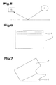
- FIG. 6 illustrates a front view of the casting vessel from FIGS. 1 to 4 ;
- FIG. 7 illustrates a variant of a casting vessel
- FIG. 8 is a perspective view illustrating a part of a device proposed by the invention.
- FIG. 9 illustrates a section through the device illustrated in FIG. 8 .
- the type of casting used by the method of casting a cast part as proposed by the invention is based on the tilt pour casting principle.
- the method proposed by the invention is known as balanced level casting. Accordingly, a metal melt 1 is poured from a tiltable casting vessel 2 into a casting mold 3 with a cavity 4 that forms the cast part.
- FIGS. 1-4 illustrate the casting vessel 2 and casting mold 3 in different consecutive positions over a period of time. The pouring operation may also be carried out using two or more casting vessels 2 disposed parallel with one another, for example casting ladles.
- the timing of the sequence starts with FIG. 1 and ends with FIG. 4 .
- the operation of pouring the metal melt 1 can be initiated by tilting the casting vessel 2 in the direction of the casting mold 3 . After this, the casting vessel and casting mold can be tilted jointly and in the same direction during the process of pouring the metal melt.
- the casting vessel 2 and casting mold 3 are positioned adjacent to one another before pouring the metal melt 1 .
- the casting vessel 2 may be spatially separated from the casting mold 3 .
- the casting vessel 2 can be moved to the casting mold 3 , for example by a robot arm, and secured to the casting mold 3 by the robot arm.
- the robot arm is indicated by broken lines in FIG. 3 and is denoted by reference 13 .
- the casting vessel 2 may also be mechanically connected the casting mold 3 and sealed, for example by suspending the casting vessel 2 in the casting mold 3 .
- the casting mold 3 and casting vessel 2 can then be jointly tilted about an axis. Having connected the casting vessel 2 to the casting mold 3 , the robot arm 13 can then release the casting vessel 2 and is then available for some other work operation.
- the metal melt 1 in the casting vessel 2 is settled. This is done by waiting until the position of the metal melt 1 in the casting vessel 2 has stabilized and has assumed a constant level. To this end, the casting vessel 2 and casting mold 3 are positioned so that a settled level a of the metal melt 1 before pouring the metal melt from the casting vessel 2 into the casting mold 3 lies at the same height in the casting vessel 2 as a section of an inner surface of the casting mold 3 , as illustrated in FIG. 1 .
- the purpose of settling the metal melt 1 in the casting vessel 2 is to ensure that pouring is as smooth as possible.
- the level of the melt can be detected by means of one or more sensors.
- the casting vessel 2 may also be filled with an inert gas. An embodiment such as that illustrated in FIG. 6 in which the casting vessel 2 can be closed by means of a cover 19 after filling it with metal melt 1 is particularly suitable for this purpose.
- the casting vessel 2 may have at least one flat base portion 5 extending in a straight line and before pouring, the casting vessel 2 is positioned so that the settled level a of the metal melt at the start of the pouring operation extends parallel with the base portion 5 .
- the casting vessel 2 may also have a differently shaped base, for example rounded.
- the casting vessel 2 and casting mold 3 before pouring the metal melt 1 can be positioned so that a normal n 1 to the base portion 5 and an opening 6 of the casting vessel 2 lying opposite the base portion and a normal n 2 to a cast-in opening 7 of the casting mold 3 subtend an angle ⁇ of ca. 45°-100°.
- This angle ⁇ may remain constant during pouring so that the relative position of the casting vessel 2 and casting mold 3 remains unchanged during pouring.
- the angle ⁇ may be varied during pouring, in which case the relative mutual positions of the casting vessel 2 and casting mold 3 will change.
- the method proposed by the invention enables the settled level a of the metal melt 1 , which necessarily sits horizontally, to be kept parallel with a base of the casting vessel 2 and to be so at the instant when pouring is initiated, and this level a more preferably corresponds to the deepest level of the mold cavity 4 of the casting mold 3 at the start of the pouring operation. From the position illustrated at the start of the pouring operation, the casting mold 3 has been pivoted by ca. ⁇ 90° as illustrated in FIG. 4 by the time pouring is terminated, as may be seen by comparing FIGS. 1 and 4 . Based on the balanced level casting method proposed by the invention, the movements of the casting vessel and/or casting mold may be controlled during the pouring operation so that the surface of the melt is more or less smooth during the entire pouring process.
- the casting vessel 2 filled with the metal melt 1 can be moved to the casting mold with a pendulum motion, for example, and the pendulum motion may be effected in the direction opposite oscillations of the metal melt 1 .
- the casting vessel 2 may have a gate opening directly into the mold cavity 4 , and the mold cavity 4 is directly connected via a gate to the casting vessel 2 during the process of pouring the metal melt 1 .
- the gate of the casting vessel 2 may be formed by a section 12 of the casting vessel 2 having a pouring opening 18 as illustrated in FIG. 6 .
- the casting mold 3 may be provided with a gate 8 .
- This gate 8 may have several passages 9 , 10 , 11 which may be used to fill the mold cavity 4 and to vent it during filling.
- the casting vessel 2 On a side facing the casting mold 3 , the casting vessel 2 may also have a section 12 co-operating with the gate 8 to guarantee a good connection between the casting vessel 2 and casting mold 3 .
- the section 12 and a section of the gate 8 co-operating with it are preferably disposed congruently with one another and the section 12 may locate in the gate 8 and be surrounded by it to enable a mechanical connection to be established between the casting vessel 2 and casting mold 3 .
- the gate 8 may extend across essentially an entire width of the mold cavity 4 facing the casting vessel 2 . Some of the metal melt may also remain in the gate 8 as a feeder volume.
- the device 14 for implementing the method proposed by the invention illustrated in FIG. 3 may comprise one or more sensors 15 for detecting the level of the metal melt 1 in the casting vessel 2 as well as a controller 16 connected to the sensor 15 , for example a signal processor or microprocessor programmed accordingly, configured to control the robot arm 13 as a function of signals generated by the sensor 15 .
- the sensor 15 may be a light-sensitive sensor, for example, which receives light from a light source 20 reflected on the surface of the metal melt and converts it into electric signals. The intensity of the light measured by the sensor 15 varies with oscillations of the level of the metal melt compared with a settled surface, making it possible to detect whether the level of the metal melt 1 has settled with the set-up described above.
- the controller 16 may be configured to control the movement of the robot arm 13 and an actuator 17 for operating the casting mold 3 in such a way that the level of the metal melt 1 is settled at the start of pouring the metal melt 1 from the casting vessel 2 into the casting mold 3 and lies at the same height as an inner surface of the casting mold 3 .
- the casting mold 3 can be tilted with the aid of the actuator, for example of another robot arm or a motor.
- the casting vessel 2 may have a pouring opening 18 at a connection point to a casting mold 3 .
- the pouring opening 18 may extend across the entire width of the mold cavity 4 .
- a movable cover may also be provided for the pouring opening 18 .
- the cover may be a closing cap for the pouring opening 18 or a plate which can be displaced in the plane of the pouring opening 18 .
- the cover 19 may also be a pivotable lid as illustrated in FIG. 7 .
- FIG. 7 is suitable if using an inert gas because the casting vessel 2 can be closed by the lid once filled with melt and the casting vessel 2 can be filled with inert gas via an intake orifice provided with a valve, for example, although this is not illustrated.
- the casting vessel 2 and casting mold 3 can be connected to one another, and the casting vessel can be suspended in the casting mold 3 and locked there.
- the connection between the casting vessel 2 and casting mold 3 may be based on a positive and/or non-positive connection.
- an end face 21 of the casting vessel 2 facing the casting mold 3 extends parallel with an end face 22 of a feeder 23 and lies against it.
- the feeder 23 may be provided in the form of a sand mold 24 .
- the end faces 21 , 22 of the casting vessel 2 and feeder 23 as well as the sand mold 24 may be complementary in terms of their surfaces and their contours.
- the end faces 21 , 22 may also be disposed congruently with one another.
- one of the end faces 21 , 22 may have one or more projections whilst the other one of the end faces 21 , 22 has complementary recesses.
- the sand mold 24 is also often referred to as a “cover core”.
- the feeder 23 is part of the pouring system and is a so-called open feeder.
- An external face 26 of the casting vessel 2 facing an external face 25 of the casting mold 3 and the external face 25 may subtend an acute angle, in other words an angle of less than 90°.
- An inner surface 27 of the casting vessel 2 and the external face 26 may extend parallel with one another.
- the casting vessel 2 may have a pouring edge 28 across which the melt passes into the casting mold 3 .
- the width of the pouring edge 28 may correspond to a width of the feeder 23 and/or a width of the sand mold 24 inserted in the feeder 23 .
- the pouring edge 28 and a cast-in edge of the sand mold 24 may be steplessly aligned with one another or may form a step, the height of which is less than 10 mm.
- the cast-in edge of the sand mold 24 is not provided with a separate reference number in FIG. 9 in order to retain clarity in the drawing. However, the cast-in edge is positioned directly adjoining the pouring edge denoted by reference number 28 .
- a surface of the sand mold 24 may be of a flat design in the region adjoining its cast-in edge and subtends an angle of between 80 and 100°, preferably an angle of between 85° and 95°, with the end face 22 . Based on the diagram in FIG. 9 , the angle between the surface of the sand mold and the end face is approximately 90°, for example.
- the surface of the sand mold 24 may have a section subtending an angle of more than 90°, preferably an angle of more than 100° and less than 160°, with the region of the surface of the sand mold 24 adjoining the cast-in edge.
- the embodiments illustrated in FIGS. 8 and 9 are also very well suited to implementing the method proposed by the invention, and the embodiments illustrated in FIGS. 8 and 9 may additionally also incorporate all the device features of the embodiments illustrated in FIGS. 1 to 7 .
Landscapes
- Engineering & Computer Science (AREA)
- Mechanical Engineering (AREA)
- Casting Support Devices, Ladles, And Melt Control Thereby (AREA)
- Molds, Cores, And Manufacturing Methods Thereof (AREA)
Applications Claiming Priority (5)
| Application Number | Priority Date | Filing Date | Title |
|---|---|---|---|
| ATA50356/2013A AT514648B1 (de) | 2013-05-27 | 2013-05-27 | Verfahren zum Kippgießen |
| ATA50356/2013 | 2013-05-27 | ||
| ATA50509/2013A AT514740B1 (de) | 2013-05-27 | 2013-08-16 | Verfahren und Vorrichtung zum Gießen eines Gussteils |
| ATA50509/2013 | 2013-08-16 | ||
| PCT/AT2014/050124 WO2014190366A1 (de) | 2013-05-27 | 2014-05-27 | Verfahren und vorrichtung zum giessen eines gussteils |
Publications (2)
| Publication Number | Publication Date |
|---|---|
| US20160101467A1 US20160101467A1 (en) | 2016-04-14 |
| US9895743B2 true US9895743B2 (en) | 2018-02-20 |
Family
ID=51229760
Family Applications (1)
| Application Number | Title | Priority Date | Filing Date |
|---|---|---|---|
| US14/893,750 Active 2034-11-05 US9895743B2 (en) | 2013-05-27 | 2014-05-27 | Method and device for casting a cast part |
Country Status (9)
| Country | Link |
|---|---|
| US (1) | US9895743B2 (de) |
| EP (1) | EP3003604B1 (de) |
| CN (1) | CN105377473B (de) |
| AT (1) | AT514740B1 (de) |
| DE (1) | DE212014000131U1 (de) |
| ES (1) | ES2702180T3 (de) |
| MX (1) | MX374602B (de) |
| PL (1) | PL3003604T3 (de) |
| WO (1) | WO2014190366A1 (de) |
Cited By (2)
| Publication number | Priority date | Publication date | Assignee | Title |
|---|---|---|---|---|
| US11141780B2 (en) * | 2015-10-14 | 2021-10-12 | Aleris Rolled Products Germany Gmbh | Method and device for casting metal alloy ingots |
| US20220143689A1 (en) * | 2019-04-09 | 2022-05-12 | Atlas Copco Airpower, Naamloze Vennootschap | Method and device for casting a rotor of a compressor, vacuum pump and/or expander device with a longitudinal axis |
Families Citing this family (6)
| Publication number | Priority date | Publication date | Assignee | Title |
|---|---|---|---|---|
| DE102014102724A1 (de) | 2013-12-03 | 2015-06-03 | Nemak Linz Gmbh | Verfahren zum gießtechnischen Erzeugen von Gussteilen aus einer Metallschmelze |
| ES2785088A1 (es) * | 2019-04-01 | 2020-10-05 | Blasco Maria Gimenez | Procedimiento de control de una maquina de moldeo mediante un robot asociado |
| EP4474078A1 (de) * | 2023-06-09 | 2024-12-11 | Heinrich Wagner Sinto Maschinenfabrik GmbH | Giessmaschine und verfahren zum giessen |
| EP4474080A1 (de) * | 2023-06-09 | 2024-12-11 | Heinrich Wagner Sinto Maschinenfabrik GmbH | Giessmaschine und verfahren zum giessen |
| EP4474079A1 (de) * | 2023-06-09 | 2024-12-11 | Heinrich Wagner Sinto Maschinenfabrik GmbH | Giessmaschine und verfahren zum giessen |
| CN120533023B (zh) * | 2025-07-28 | 2025-11-04 | 郴州兴城环保股份有限公司 | 一种防溅射的贵金属用浇铸设备 |
Citations (21)
| Publication number | Priority date | Publication date | Assignee | Title |
|---|---|---|---|---|
| US1189548A (en) | 1913-11-10 | 1916-07-04 | Pierre Henri Gaston Durville | Apparatus for and process of casting ingots of metals and alloys. |
| DE686764C (de) | 1934-10-17 | 1940-01-16 | Neunkircher Eisenwerk A G Vorm | Vorrichtung zum Giessen von Flusseisen und Stahl in Blockformen |
| US3435883A (en) | 1968-03-07 | 1969-04-01 | Fromson H A | Art of casting fusible materials |
| CH477931A (de) | 1967-07-06 | 1969-09-15 | Fromson H A | Giessverfahren |
| JPH02175065A (ja) * | 1988-12-27 | 1990-07-06 | Asahi Tec Corp | 砂型を用いた可傾鋳造法 |
| EP0592365A1 (de) | 1992-10-07 | 1994-04-13 | Maschinenfabrik & Eisengiesserei Ed. Mezger AG. | Verfahren und Vorrichtung zur Bewegungssteuerung einer Giesspfanne in einer Giessanlage |
| JPH08168871A (ja) | 1994-12-16 | 1996-07-02 | Meidensha Corp | 注湯装置 |
| US5704413A (en) | 1993-11-30 | 1998-01-06 | Honda Giken Kogyo Kabushiki Kaisha | Rotary-mold gravity casting process |
| EP1155763A1 (de) | 2000-04-19 | 2001-11-21 | VAW mandl & berger GmbH | Verfahren und Vorrichtung zum Rotationsgiessen |
| US20050023737A1 (en) * | 2003-04-04 | 2005-02-03 | Honda Motor Co., Ltd. | Ladle |
| DE102004015649B3 (de) | 2004-03-31 | 2005-08-25 | Rautenbach-Guß Wernigerode GmbH | Verfahren und Vorrichtung zum Giessen von Bauteilen aus Leichtmetall nach dem Kippgiessprinzip |
| DE102006058142A1 (de) | 2006-12-09 | 2008-06-12 | Volkswagen Ag | Verfahren und Vorrichtung zum Kippgießen von Bauteilen aus Leichtmetall |
| US20090229782A1 (en) * | 2008-03-11 | 2009-09-17 | The Yokohama Rubber Co., Ltd. | Casting apparatus |
| DE102009023881A1 (de) | 2008-06-06 | 2010-01-28 | GM Global Technology Operations, Inc., Detroit | Pfanne für eine Metallschmelze |
| DE202009012656U1 (de) | 2008-09-23 | 2010-02-11 | Fill Gesellschaft M.B.H. | Vorrichtung zum Gießen mit einer Kokille |
| WO2010058003A1 (de) | 2008-11-24 | 2010-05-27 | Nemak Dillingen Gmbh | VERFAHREN UND VORRICHTUNG ZUM GIEßEN EINES GUSSTEILS AUS EINER METALLSCHMELZE |
| WO2010068113A1 (en) | 2008-12-11 | 2010-06-17 | Oshaug Metall As | A method of casting metals in a mould |
| US20100324719A1 (en) | 2008-05-16 | 2010-12-23 | Kazuhiro Ota | Method and system for damping sloshing molten metal |
| DE102010023646A1 (de) | 2009-07-03 | 2011-01-05 | Ksm Castings Gmbh | Vorrichtung, Gießrinne und Verfahren zum Kippgießen von Bauteilen aus Leichtmetall sowie damit gegossene Bauteile |
| DE102010022343A1 (de) | 2010-06-01 | 2011-12-01 | Volkswagen Ag | Verfahren zum Kippgießen von Bauteilen und Kippgießvorrichtung |
| WO2013017371A1 (de) | 2011-08-02 | 2013-02-07 | Ks Aluminium-Technologie Gmbh | VERFAHREN UND VORRICHTUNG ZUR HERSTELLUNG EINES LEICHTMETALLBAUTEILS DURCH KIPPGIEßEN |
Family Cites Families (7)
| Publication number | Priority date | Publication date | Assignee | Title |
|---|---|---|---|---|
| DE606988C (de) | 1932-08-06 | 1934-12-14 | Fried Krupp Grusonwerk Akt Ges | Vorrichtung zum Giessen von Metallbloecken |
| JPS5396920A (en) | 1977-02-04 | 1978-08-24 | Honda Kinzoku Gijutsu Kk | Casting machine |
| JPH1043853A (ja) | 1996-08-05 | 1998-02-17 | Asahi Tec Corp | 可傾鋳造方法及びその装置 |
| DE10112621A1 (de) | 2001-03-14 | 2002-09-19 | Km Europa Metal Ag | Anordnung zum Abgießen einer aus einer Kupferlegierung bestehenden Gießschmelze |
| US6896032B1 (en) | 2002-09-26 | 2005-05-24 | Hayes Lemmerz International, Inc. | Stopper-poured molten metal casting vessel with constant head height |
| US7025115B2 (en) | 2004-08-11 | 2006-04-11 | General Motors Corporation | Ladle for molten metal |
| JP5647552B2 (ja) | 2011-03-23 | 2014-12-24 | リョービ株式会社 | 傾動式重力鋳造法 |
-
2013
- 2013-08-16 AT ATA50509/2013A patent/AT514740B1/de active
-
2014
- 2014-05-27 CN CN201480039878.4A patent/CN105377473B/zh active Active
- 2014-05-27 US US14/893,750 patent/US9895743B2/en active Active
- 2014-05-27 PL PL14744419T patent/PL3003604T3/pl unknown
- 2014-05-27 EP EP14744419.4A patent/EP3003604B1/de active Active
- 2014-05-27 ES ES14744419T patent/ES2702180T3/es active Active
- 2014-05-27 MX MX2015016190A patent/MX374602B/es active IP Right Grant
- 2014-05-27 DE DE212014000131.5U patent/DE212014000131U1/de not_active Expired - Lifetime
- 2014-05-27 WO PCT/AT2014/050124 patent/WO2014190366A1/de not_active Ceased
Patent Citations (28)
| Publication number | Priority date | Publication date | Assignee | Title |
|---|---|---|---|---|
| US1189548A (en) | 1913-11-10 | 1916-07-04 | Pierre Henri Gaston Durville | Apparatus for and process of casting ingots of metals and alloys. |
| DE686764C (de) | 1934-10-17 | 1940-01-16 | Neunkircher Eisenwerk A G Vorm | Vorrichtung zum Giessen von Flusseisen und Stahl in Blockformen |
| CH477931A (de) | 1967-07-06 | 1969-09-15 | Fromson H A | Giessverfahren |
| US3435883A (en) | 1968-03-07 | 1969-04-01 | Fromson H A | Art of casting fusible materials |
| JPH02175065A (ja) * | 1988-12-27 | 1990-07-06 | Asahi Tec Corp | 砂型を用いた可傾鋳造法 |
| US5381855A (en) | 1992-10-07 | 1995-01-17 | Maschinenfabrik & Eisengiesserei Ed. Mezger Ag | Method of and apparatus for controlling the motion of a pouring ladle |
| EP0592365A1 (de) | 1992-10-07 | 1994-04-13 | Maschinenfabrik & Eisengiesserei Ed. Mezger AG. | Verfahren und Vorrichtung zur Bewegungssteuerung einer Giesspfanne in einer Giessanlage |
| US5704413A (en) | 1993-11-30 | 1998-01-06 | Honda Giken Kogyo Kabushiki Kaisha | Rotary-mold gravity casting process |
| JPH08168871A (ja) | 1994-12-16 | 1996-07-02 | Meidensha Corp | 注湯装置 |
| EP1155763A1 (de) | 2000-04-19 | 2001-11-21 | VAW mandl & berger GmbH | Verfahren und Vorrichtung zum Rotationsgiessen |
| US6715535B2 (en) | 2000-04-19 | 2004-04-06 | Vaw Mandl & Berger Gmbh | Method of and device for rotary casting |
| US20050023737A1 (en) * | 2003-04-04 | 2005-02-03 | Honda Motor Co., Ltd. | Ladle |
| DE102004015649B3 (de) | 2004-03-31 | 2005-08-25 | Rautenbach-Guß Wernigerode GmbH | Verfahren und Vorrichtung zum Giessen von Bauteilen aus Leichtmetall nach dem Kippgiessprinzip |
| DE102006058142A1 (de) | 2006-12-09 | 2008-06-12 | Volkswagen Ag | Verfahren und Vorrichtung zum Kippgießen von Bauteilen aus Leichtmetall |
| US20090229782A1 (en) * | 2008-03-11 | 2009-09-17 | The Yokohama Rubber Co., Ltd. | Casting apparatus |
| US20100324719A1 (en) | 2008-05-16 | 2010-12-23 | Kazuhiro Ota | Method and system for damping sloshing molten metal |
| US8245759B2 (en) | 2008-06-06 | 2012-08-21 | GM Global Technology Operations LLC | Ladle for molten metal |
| DE102009023881A1 (de) | 2008-06-06 | 2010-01-28 | GM Global Technology Operations, Inc., Detroit | Pfanne für eine Metallschmelze |
| DE202009012656U1 (de) | 2008-09-23 | 2010-02-11 | Fill Gesellschaft M.B.H. | Vorrichtung zum Gießen mit einer Kokille |
| WO2010058003A1 (de) | 2008-11-24 | 2010-05-27 | Nemak Dillingen Gmbh | VERFAHREN UND VORRICHTUNG ZUM GIEßEN EINES GUSSTEILS AUS EINER METALLSCHMELZE |
| US8302659B2 (en) | 2008-11-24 | 2012-11-06 | Nemak Dillingen Gmbh | Method and device for casting a cast part from a metal melt |
| WO2010068113A1 (en) | 2008-12-11 | 2010-06-17 | Oshaug Metall As | A method of casting metals in a mould |
| DE102010023646A1 (de) | 2009-07-03 | 2011-01-05 | Ksm Castings Gmbh | Vorrichtung, Gießrinne und Verfahren zum Kippgießen von Bauteilen aus Leichtmetall sowie damit gegossene Bauteile |
| US8770264B2 (en) | 2009-07-03 | 2014-07-08 | Ksm Castings Group Gmbh | Device, gutter, method for tilt-casting components made of light metal, and components cast therewith |
| WO2011151007A1 (de) | 2010-06-01 | 2011-12-08 | Volkswagen Aktiengesellschaft | Verfahren zum kippgiessen von bauteilen und kippgiessvorrichtung |
| DE102010022343A1 (de) | 2010-06-01 | 2011-12-01 | Volkswagen Ag | Verfahren zum Kippgießen von Bauteilen und Kippgießvorrichtung |
| WO2013017371A1 (de) | 2011-08-02 | 2013-02-07 | Ks Aluminium-Technologie Gmbh | VERFAHREN UND VORRICHTUNG ZUR HERSTELLUNG EINES LEICHTMETALLBAUTEILS DURCH KIPPGIEßEN |
| DE102011052366A1 (de) | 2011-08-02 | 2013-02-07 | Ks Aluminium-Technologie Gmbh | Verfahren und Vorrichtung zur Herstellung eines Leichtmetallbauteils durch Kippgießen |
Non-Patent Citations (2)
| Title |
|---|
| English machine translation of DE102006058142. * |
| International Search Report of PCT/AT2014/050124, dated Oct. 30, 2014. |
Cited By (3)
| Publication number | Priority date | Publication date | Assignee | Title |
|---|---|---|---|---|
| US11141780B2 (en) * | 2015-10-14 | 2021-10-12 | Aleris Rolled Products Germany Gmbh | Method and device for casting metal alloy ingots |
| US20220143689A1 (en) * | 2019-04-09 | 2022-05-12 | Atlas Copco Airpower, Naamloze Vennootschap | Method and device for casting a rotor of a compressor, vacuum pump and/or expander device with a longitudinal axis |
| US11673189B2 (en) * | 2019-04-09 | 2023-06-13 | Atlas Copco Airpower, Naamloze Vennootschap | Method and device for casting a rotor of a compressor, vacuum pump and/or expander device with a longitudinal axis |
Also Published As
| Publication number | Publication date |
|---|---|
| MX374602B (es) | 2025-03-06 |
| EP3003604A1 (de) | 2016-04-13 |
| PL3003604T3 (pl) | 2019-07-31 |
| WO2014190366A1 (de) | 2014-12-04 |
| AT514740B1 (de) | 2020-12-15 |
| EP3003604B1 (de) | 2018-10-03 |
| AT514740A1 (de) | 2015-03-15 |
| CN105377473B (zh) | 2019-01-22 |
| US20160101467A1 (en) | 2016-04-14 |
| DE212014000131U1 (de) | 2016-01-13 |
| CN105377473A (zh) | 2016-03-02 |
| ES2702180T3 (es) | 2019-02-27 |
Similar Documents
| Publication | Publication Date | Title |
|---|---|---|
| US9895743B2 (en) | Method and device for casting a cast part | |
| US10537937B2 (en) | Pouring machine and method | |
| US20090230159A1 (en) | Method for pouring off melt from a tiltable metallurgical vessel and installation for carrying out the method | |
| US8245759B2 (en) | Ladle for molten metal | |
| CN102935499A (zh) | 一种为给汤机配套的汤杯 | |
| CN108421969A (zh) | 一种自动浇铸系统 | |
| CN107073574A (zh) | 冲击垫、包括冲击垫的浇注盘和设备、及其使用方法 | |
| CN105562669A (zh) | 一种浇注位置可调式浇包装置 | |
| CN105499551A (zh) | 一种封闭式浇注包及其使用方法 | |
| CN109822082A (zh) | 一种模具自动浇铸流量控制方法 | |
| JP2000301297A (ja) | タンディッシュ | |
| CN208758571U (zh) | 一种锥形浇口杯 | |
| CN109014165A (zh) | 一种带有封盖结构的铸造铁水包 | |
| JPH065012Y2 (ja) | 傾動注湯容器 | |
| JP2019524450A (ja) | タンディッシュ漏斗 | |
| JPH0847753A (ja) | 連続鋳造装置 | |
| RU2115510C1 (ru) | Способ отделения шлака от металла в стопорном ковше в конце заливки металла | |
| US4928862A (en) | Tiltable ladle and cover for such ladle | |
| JP5361212B2 (ja) | タンディッシュへの溶鋼注入方法 | |
| CN209239044U (zh) | 铸造底注式浇包 | |
| JPH05293625A (ja) | 鋳造装置 | |
| US4129288A (en) | Hood to be used in a metal production plant | |
| SU472744A1 (ru) | Изложница дл отливки слитков | |
| JPS5940132Y2 (ja) | 加圧式自動注湯装置 | |
| RU2763994C1 (ru) | Устройство и способ управления непрерывной разливкой |
Legal Events
| Date | Code | Title | Description |
|---|---|---|---|
| AS | Assignment |
Owner name: FILL GESELLSCHAFT M.B.H., AUSTRIA Free format text: ASSIGNMENT OF ASSIGNORS INTEREST;ASSIGNOR:RATHNER, WOLFGANG;REEL/FRAME:037133/0764 Effective date: 20151119 |
|
| STCF | Information on status: patent grant |
Free format text: PATENTED CASE |
|
| AS | Assignment |
Owner name: NEMAK, S.A.B. DE C.V., MEXICO Free format text: ASSIGNMENT OF ASSIGNORS INTEREST;ASSIGNOR:NEMAK EUROPE GMBH;REEL/FRAME:046546/0474 Effective date: 20180704 Owner name: NEMAK EUROPE GMBH, GERMANY Free format text: ASSIGNMENT OF ASSIGNORS INTEREST;ASSIGNOR:FILL GESELLSCHAFT M.B.H.;REEL/FRAME:046702/0398 Effective date: 20171228 |
|
| MAFP | Maintenance fee payment |
Free format text: PAYMENT OF MAINTENANCE FEE, 4TH YEAR, LARGE ENTITY (ORIGINAL EVENT CODE: M1551); ENTITY STATUS OF PATENT OWNER: LARGE ENTITY Year of fee payment: 4 |
|
| MAFP | Maintenance fee payment |
Free format text: PAYMENT OF MAINTENANCE FEE, 8TH YEAR, LARGE ENTITY (ORIGINAL EVENT CODE: M1552); ENTITY STATUS OF PATENT OWNER: LARGE ENTITY Year of fee payment: 8 |