WO1995013401A1 - Procede de production de tole d'acier a champ electromagnetique directionnel avec chauffage de brames a basse temperature - Google Patents

Procede de production de tole d'acier a champ electromagnetique directionnel avec chauffage de brames a basse temperature Download PDF

Info

Publication number
WO1995013401A1
WO1995013401A1 PCT/KR1994/000160 KR9400160W WO9513401A1 WO 1995013401 A1 WO1995013401 A1 WO 1995013401A1 KR 9400160 W KR9400160 W KR 9400160W WO 9513401 A1 WO9513401 A1 WO 9513401A1
Authority
WO
WIPO (PCT)
Prior art keywords
annealing
temperature
final
less
grain
Prior art date
Legal status (The legal status is an assumption and is not a legal conclusion. Google has not performed a legal analysis and makes no representation as to the accuracy of the status listed.)
Ceased
Application number
PCT/KR1994/000160
Other languages
English (en)
French (fr)
Inventor
Gyu Seung Choi
Chung San Lee
Jong Soo Woo
Byung Deug HONG
Current Assignee (The listed assignees may be inaccurate. Google has not performed a legal analysis and makes no representation or warranty as to the accuracy of the list.)
Research Institute of Industrial Science and Technology RIST
Posco Holdings Inc
Original Assignee
Research Institute of Industrial Science and Technology RIST
Pohang Iron and Steel Co Ltd
Priority date (The priority date is an assumption and is not a legal conclusion. Google has not performed a legal analysis and makes no representation as to the accuracy of the date listed.)
Filing date
Publication date
Priority claimed from KR1019930023751A external-priority patent/KR960006026B1/ko
Priority claimed from KR1019940021389A external-priority patent/KR970007031B1/ko
Priority claimed from KR1019940021388A external-priority patent/KR970007030B1/ko
Priority claimed from KR1019940021391A external-priority patent/KR970007033B1/ko
Priority claimed from KR1019940021390A external-priority patent/KR970007032B1/ko
Application filed by Research Institute of Industrial Science and Technology RIST, Pohang Iron and Steel Co Ltd filed Critical Research Institute of Industrial Science and Technology RIST
Priority to EP95900316A priority Critical patent/EP0709470B1/en
Priority to DE69428537T priority patent/DE69428537T2/de
Priority to US08/481,353 priority patent/US5653821A/en
Publication of WO1995013401A1 publication Critical patent/WO1995013401A1/ja
Anticipated expiration legal-status Critical
Ceased legal-status Critical Current

Links

Classifications

    • CCHEMISTRY; METALLURGY
    • C22METALLURGY; FERROUS OR NON-FERROUS ALLOYS; TREATMENT OF ALLOYS OR NON-FERROUS METALS
    • C22CALLOYS
    • C22C38/00Ferrous alloys, e.g. steel alloys
    • C22C38/02Ferrous alloys, e.g. steel alloys containing silicon
    • CCHEMISTRY; METALLURGY
    • C21METALLURGY OF IRON
    • C21DMODIFYING THE PHYSICAL STRUCTURE OF FERROUS METALS; GENERAL DEVICES FOR HEAT TREATMENT OF FERROUS OR NON-FERROUS METALS OR ALLOYS; MAKING METAL MALLEABLE, e.g. BY DECARBURISATION OR TEMPERING
    • C21D8/00Modifying the physical properties of ferrous metals or ferrous alloys by deformation combined with, or followed by, heat treatment
    • C21D8/12Modifying the physical properties of ferrous metals or ferrous alloys by deformation combined with, or followed by, heat treatment during manufacturing of articles with special electromagnetic properties
    • C21D8/1205Modifying the physical properties of ferrous metals or ferrous alloys by deformation combined with, or followed by, heat treatment during manufacturing of articles with special electromagnetic properties involving particular fabrication steps or treatments of ingots or slabs
    • HELECTRICITY
    • H04ELECTRIC COMMUNICATION TECHNIQUE
    • H04NPICTORIAL COMMUNICATION, e.g. TELEVISION
    • H04N19/00Methods or arrangements for coding, decoding, compressing or decompressing digital video signals
    • H04N19/10Methods or arrangements for coding, decoding, compressing or decompressing digital video signals using adaptive coding
    • H04N19/102Methods or arrangements for coding, decoding, compressing or decompressing digital video signals using adaptive coding characterised by the element, parameter or selection affected or controlled by the adaptive coding
    • H04N19/103Selection of coding mode or of prediction mode
    • H04N19/107Selection of coding mode or of prediction mode between spatial and temporal predictive coding, e.g. picture refresh
    • HELECTRICITY
    • H04ELECTRIC COMMUNICATION TECHNIQUE
    • H04NPICTORIAL COMMUNICATION, e.g. TELEVISION
    • H04N19/00Methods or arrangements for coding, decoding, compressing or decompressing digital video signals
    • H04N19/10Methods or arrangements for coding, decoding, compressing or decompressing digital video signals using adaptive coding
    • H04N19/102Methods or arrangements for coding, decoding, compressing or decompressing digital video signals using adaptive coding characterised by the element, parameter or selection affected or controlled by the adaptive coding
    • H04N19/103Selection of coding mode or of prediction mode
    • H04N19/114Adapting the group of pictures [GOP] structure, e.g. number of B-frames between two anchor frames
    • HELECTRICITY
    • H04ELECTRIC COMMUNICATION TECHNIQUE
    • H04NPICTORIAL COMMUNICATION, e.g. TELEVISION
    • H04N19/00Methods or arrangements for coding, decoding, compressing or decompressing digital video signals
    • H04N19/10Methods or arrangements for coding, decoding, compressing or decompressing digital video signals using adaptive coding
    • H04N19/169Methods or arrangements for coding, decoding, compressing or decompressing digital video signals using adaptive coding characterised by the coding unit, i.e. the structural portion or semantic portion of the video signal being the object or the subject of the adaptive coding
    • H04N19/177Methods or arrangements for coding, decoding, compressing or decompressing digital video signals using adaptive coding characterised by the coding unit, i.e. the structural portion or semantic portion of the video signal being the object or the subject of the adaptive coding the unit being a group of pictures [GOP]
    • HELECTRICITY
    • H04ELECTRIC COMMUNICATION TECHNIQUE
    • H04NPICTORIAL COMMUNICATION, e.g. TELEVISION
    • H04N19/00Methods or arrangements for coding, decoding, compressing or decompressing digital video signals
    • H04N19/10Methods or arrangements for coding, decoding, compressing or decompressing digital video signals using adaptive coding
    • H04N19/169Methods or arrangements for coding, decoding, compressing or decompressing digital video signals using adaptive coding characterised by the coding unit, i.e. the structural portion or semantic portion of the video signal being the object or the subject of the adaptive coding
    • H04N19/179Methods or arrangements for coding, decoding, compressing or decompressing digital video signals using adaptive coding characterised by the coding unit, i.e. the structural portion or semantic portion of the video signal being the object or the subject of the adaptive coding the unit being a scene or a shot
    • HELECTRICITY
    • H04ELECTRIC COMMUNICATION TECHNIQUE
    • H04NPICTORIAL COMMUNICATION, e.g. TELEVISION
    • H04N19/00Methods or arrangements for coding, decoding, compressing or decompressing digital video signals
    • H04N19/60Methods or arrangements for coding, decoding, compressing or decompressing digital video signals using transform coding
    • H04N19/61Methods or arrangements for coding, decoding, compressing or decompressing digital video signals using transform coding in combination with predictive coding
    • HELECTRICITY
    • H04ELECTRIC COMMUNICATION TECHNIQUE
    • H04NPICTORIAL COMMUNICATION, e.g. TELEVISION
    • H04N19/00Methods or arrangements for coding, decoding, compressing or decompressing digital video signals
    • H04N19/85Methods or arrangements for coding, decoding, compressing or decompressing digital video signals using pre-processing or post-processing specially adapted for video compression
    • H04N19/87Methods or arrangements for coding, decoding, compressing or decompressing digital video signals using pre-processing or post-processing specially adapted for video compression involving scene cut or scene change detection in combination with video compression
    • CCHEMISTRY; METALLURGY
    • C21METALLURGY OF IRON
    • C21DMODIFYING THE PHYSICAL STRUCTURE OF FERROUS METALS; GENERAL DEVICES FOR HEAT TREATMENT OF FERROUS OR NON-FERROUS METALS OR ALLOYS; MAKING METAL MALLEABLE, e.g. BY DECARBURISATION OR TEMPERING
    • C21D3/00Diffusion processes for extraction of non-metals; Furnaces therefor
    • C21D3/02Extraction of non-metals
    • C21D3/04Decarburising
    • CCHEMISTRY; METALLURGY
    • C21METALLURGY OF IRON
    • C21DMODIFYING THE PHYSICAL STRUCTURE OF FERROUS METALS; GENERAL DEVICES FOR HEAT TREATMENT OF FERROUS OR NON-FERROUS METALS OR ALLOYS; MAKING METAL MALLEABLE, e.g. BY DECARBURISATION OR TEMPERING
    • C21D8/00Modifying the physical properties of ferrous metals or ferrous alloys by deformation combined with, or followed by, heat treatment
    • C21D8/12Modifying the physical properties of ferrous metals or ferrous alloys by deformation combined with, or followed by, heat treatment during manufacturing of articles with special electromagnetic properties
    • C21D8/1244Modifying the physical properties of ferrous metals or ferrous alloys by deformation combined with, or followed by, heat treatment during manufacturing of articles with special electromagnetic properties characterised by the heat treatment
    • C21D8/1266Modifying the physical properties of ferrous metals or ferrous alloys by deformation combined with, or followed by, heat treatment during manufacturing of articles with special electromagnetic properties characterised by the heat treatment between cold rolling steps

Definitions

  • the present invention relates to a method for manufacturing a grain-oriented electrical steel sheet used as an iron core material for transformers, electric motors, generators, and other electronic devices.
  • This method relates to a method of manufacturing a grain-oriented electrical steel sheet having excellent magnetic properties through a secondary recrystallization stabilization process after heating at a temperature lower than the heating temperature.
  • the grain-oriented electrical steel sheet has a texture with a crystal grain orientation aligned in the (110) [001] direction.
  • This product has excellent magnetic properties in the rolling direction. It is used as iron core material for transformers, motors, generators, and other electronic devices.
  • This (110) [001] texture can be obtained using the current state of secondary recrystallization, but secondary recrystallization is usually Nuclei of specific orientation from fine crystal grains generated by recrystallization of
  • the nucleus having the [001] orientation was abnormally grown on the entire specimen, and the primary recrystallization was required for the smooth growth of the secondary recrystallization rate in such a specific orientation.
  • Grain-oriented electrical steel sheet products can be divided into two categories based on magnetic property values.Since the commercial production started by Armco of the United States in the early 1940s, conventional grain oriented steel sheets were almost completed in the 1960s.
  • the easy axis [001] direction has a deviation degree 7 ° from the rolling direction, the density of the magnetic flux B 1 0 reference 1. 80- 1.86 Tesla (Tes - la) levels Since then, high magnetic flux density grain-oriented electrical steel sheet, whose magnetic properties are far superior to conventional grain-oriented electrical steel sheet developed by NSC of Japan in the 1970s, that is, the magnetic flux density B10 value is 1. It can be broadly classified into products with higher efficiency characteristics, where the [001] direction has a deviation of only about 3 ° from the rolling direction at 89 Tesla or more.
  • the manufacturing process of grain-oriented electrical steel sheets is generally characterized by containing 2-4 silicon and MnS, MnSe, and A1N as grain growth inhibitors.
  • This slab reheating process involves the precipitation of MnS, A1N, etc., which are used as grain growth inhibitors.
  • the material is completely precipitated after solid solution dispersion However, it is inevitable to maintain the temperature for about 5 hours at a high temperature of about 1400 ° C.
  • oxides of Si and Fe components are formed on the surface of the high-temperature slab due to oxidation reaction with air.
  • an oxide called composite firelite (Fayalite, 2FeO ⁇ Si02) is formed, and this oxide melts down from the surface because its melting point is as low as about 1300 ° C.
  • the hot water is designed to flow down to the outside, but accumulates in the refractory etc.
  • the process is controlled by adopting the strong rolling method once. Magnetism by lot Therefore, the low-temperature reheating method cannot be applied to high-grade materials that can be sold at a high price, that is, high magnetic flux density grade grain-oriented electrical steel sheets.
  • ALSC0 of the United States reported in Japanese Patent Application Publication No. 57-158322 that it is possible to manufacture electrical steel sheets by appropriately controlling the Mn / S ratio based on low-temperature reheating operation. It was difficult to control the grain growth inhibition strength (Inhibition strength), and it was impossible to secure stable magnetism.
  • the present invention uses conventional grain-oriented electrical steel sheets with the same slurry as that for general steel.
  • the component system By designing the component system to perform hot rolling by heat treatment near the heating temperature of 1250-1320 ° C, work can be performed in existing manufacturing processes without equipment supplementation or new installation. Yes, the pre-annealing step was omitted to ensure stable formation of secondary recrystallization of defense by ensuring stable grain growth suppression power, and decarburization annealing was performed at an intermediate thickness to achieve the final pressure.
  • Another object of the present invention is to provide a method for manufacturing an improved grain-oriented electrical steel sheet capable of obtaining stable magnetic properties such as lowering the working energy during elongation.
  • the final recrystallization is controlled by controlling the rate of temperature rise in a certain temperature section appropriately during final high-temperature annealing to finely control the primary recrystallized grains and secure the driving force for secondary recrystallization.
  • Intermediate recovery annealing process performed after cold rolling to thickness It is an object of the present invention to provide a method for manufacturing a grain-oriented electrical steel sheet capable of securing magnetic properties equal to or higher than that of a normal grain-oriented electrical steel sheet, even if it is omitted.
  • the purpose is to maintain the atmosphere of the intermediate recovery annealing process in a wet atmosphere so that oxide formation is possible under the existing completely dry atmosphere, and to control the annealing temperature so as to be relatively advantageous for oxide formation.
  • the objective is to increase the amount of dissolved A1 to maintain the fundamental and more essential suppression of grain growth, optimize the control of precipitates in the intermediate process, and heat the final annealing process in the final recrystallization forming process. Strict control of the magnetic flux density to improve the magnetic flux density B10.
  • Yet another object of the present invention is to utilize a component system having a low dissolved A1 content at the time of initial steelmaking in order to satisfy the desire for a production process that must be commercialized even if it slightly deviates from the target component range.
  • C 0.035-0. 050%, Si: 2, 9-3, 3%, P: 0.015% or less, dissolved A 1; 011-0. 017%, N: 0.0080- 0.012%, S: 0.007% or less.
  • the present invention relates to a method for producing a grain-oriented electrical steel sheet having excellent magnetic properties by applying a separating agent and then performing a final finish high-temperature annealing treatment. Further, the present invention eliminates intermediate recovery annealing in the above-described production method. Instead, The heating rate during 400- 700 ° C and under high temperature annealing method for producing a grain-oriented electrical steel sheet kept below 50 ° C / hr.
  • the present invention provides the above method, wherein the intermediate recovery annealing is performed in a temperature range of 600 to 750 ° C and P H 2 .
  • the method relates to a method for producing a grain-oriented electrical steel sheet having excellent glass coating properties by conducting the coating for 45 seconds to 2 minutes in a humid atmosphere in which / P H 2 is 0.62 to 0.88.
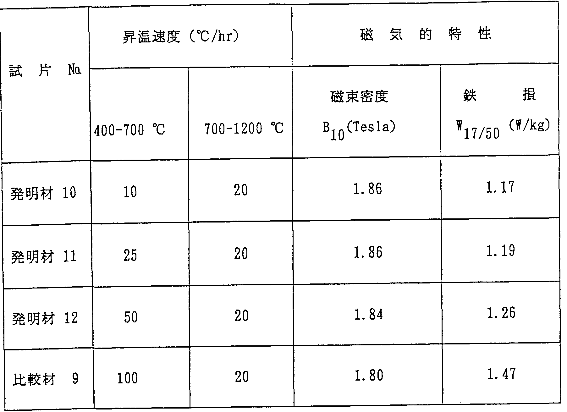
  • the present invention relates to a method for producing a grain-oriented electrical steel sheet in the above-mentioned production method, while maintaining a heating rate at 400 to 700 ° C at a final finish high-temperature annealing of 20 ° C / hr or more.
  • the present invention manufactures grain-oriented electrical steel sheets by a low-temperature slab heating method.
  • the present invention relates to a method for manufacturing high magnetic flux density grade grain-oriented electrical steel sheets.
  • the above-mentioned final finishing high-temperature annealing is performed to maintain the heating rate at 400 to 700 ° C at 50 ° C / hr or less to manufacture grain-oriented electrical steel sheets. About the method.
  • the present invention relates to a method of manufacturing a grain-oriented electrical steel sheet by a low-temperature slab heating method, wherein, by weight%, C: 0.020-0.050%, Si: 2.9-3.3%, P: 0.0016 or less, dissolved A1: 0.007-%.
  • the steel slab was reheated and hot-rolled in the temperature range of 1250 to 1320 ° C, and the hot-rolled sheet was not annealed, but was subjected to two cold rollings, including intermediate decarburization annealing, to achieve the final thickness.
  • FIG. 1 shows the magnetic flux density accompanying the change in the amount of dissolved A 1.
  • FIG. 1 shows the magnetic flux density accompanying the change in the amount of dissolved A 1.
  • FIG. 1 shows the magnetic flux density accompanying the change in the amount of dissolved A 1.
  • FIG. 1 shows the magnetic flux density accompanying the change in the amount of dissolved A 1.
  • FIG. 1 shows the magnetic flux density accompanying the change in the amount of dissolved A 1.
  • FIG. 1 shows the magnetic flux density accompanying the change in the amount of dissolved A 1.
  • secondary recrystallization Graph showing the relationship with the incidence of fine grains in grains
  • Fig. 2 shows the magnetic flux density accompanying the change in the amount of S.
  • Graph showing the relationship with the incidence of fine grains in secondary and recrystallized grains
  • Figure 3 shows the magnetic flux density associated with the change in the Mn / S ratio.
  • Graph showing the relationship between product and product adhesion
  • Fig. 4 shows the magnetic flux density B when the Cu / Mn ratio changes. And iron loss W17 / 5 .
  • Fig. 5 shows the magnetic flux density due to the slab reheating temperature change.
  • the main idea of the present invention is to design a component system capable of low-temperature slab heating and to secure a new manufacturing process for controlling an appropriate grain growth inhibitor.
  • the basic grain growth inhibitor of the present invention is A1 N, in which some of the Cu 2 S and MnS play a role.
  • the formation of precipitates of MnS used for normal high-temperature slab heating is suppressed as much as possible. It is one of the features of the present invention to control the S content to 0.007% or less, which is the minimum controllable amount in the manufacturing process, because of this feature.
  • the solid solution temperature of MnS was about 1280 ° C, followed by A1 N and Cu 2 S, which were as low as about 1200 ° C, and the precipitation temperature during hot rolling was also about 1200 ° C. Although it was C, A 1 N was lower than that, and in the case of Cu 2 S, it was confirmed to be as low as 1100 ° C.
  • MnS during hot rolling by normal high-temperature slab heating is high.
  • MnS precipitates already exist in the steel when A1N precipitates, so that precipitation of A1N precipitates around MnS occurs.
  • the A1N precipitates are affected by the MnS precipitates, and are large in size and non-uniform.
  • the present inventor has found that A, which is advantageous by low-temperature slab heating work, is used as a grain growth inhibitor, and S, which is inevitably present, precipitates as much as possible in a Cu 2 S state during hot rolling.
  • the A1N formed is not affected by MnS and forms as fine and uniform precipitates of a size effective for suppressing grain growth.
  • the amount of dissolved A1 must be limited to 0.018-0.030% when manufacturing high magnetic flux density grain-oriented electrical steel sheets according to the present invention.
  • the C content should be set slightly higher. Is required.
  • the expansion to a slightly lower range does not pose a significant problem.
  • the lower limit expansion is an important component because the C component fundamentally forms a hot-rolled structure and contributes to securing the grain growth suppressing force by applying the processing energy during cold rolling.
  • Thickness Not only the problem of improving decarburization due to decarburization, but also from the metallurgical side, there is no problem even if the processing energy during cold rolling is small because primary recrystallization itself occurs during final finish annealing. Therefore, operation control to the lower limit is much more advantageous at the work site. Furthermore, when the amount of dissolved A1 is high, there are many precipitates, so that the initial temperature during hot rolling, FTo and the size of precipitates due to the difference in FT 6 is the final temperature In addition, it affects the distribution and induces magnetic deviation in the longitudinal direction.Therefore, it was confirmed that when the amount of dissolved A1 is small, the control of precipitates is easy and the control of the magnetic deviation in the longitudinal direction is much more advantageous. .
  • the present invention can be implemented.
  • the magnetic properties are determined by how the precipitates, which are grain growth inhibitors, play a role in an optimal state during secondary recrystallization formation to some extent.
  • the component system of the present invention is an A1N center system with a small amount of S, and A1N undergoes secondary recrystallization during cooling during hot rolling. Precipitated in a fine form effective for It is necessary to perform cold rolling immediately.
  • decarburizing annealing is performed at an intermediate thickness
  • secondary rolling is performed under low carbon to reduce the additional energy accumulated in the steel sheet.
  • -It is important to perform intermediate recovery annealing at a relatively low temperature of 650 ° C so that the primary recrystallized grains can be formed finely and uniformly at the time of final finish annealing.
  • the secondary recrystallized grains formed during the final high-temperature annealing have a well-aligned texture with (110) [001], which is the direction of easy magnetization. .
  • the intermediate recovery annealing step itself performed after rolling to the final thickness can be omitted, and the metallurgical role of this part can be supplemented in the subsequent steps.
  • this can be explained as follows.
  • the annealing process after the secondary rolling is given during rolling. Recovery and primary recrystallization occur due to the applied processing energy, and this primary recrystallization formation state is the final finish after the secondary recrystallization formation utilizing the abnormal growth phenomenon of primary recrystallized grains generated in the high-temperature annealing process It will determine the state.
  • the two annealing processes performed by rolling twice have a considerable load from the aspects of equipment management and productivity and workability. As long as the magnetic properties can be ensured, a large production profit is possible. Therefore, the present inventors omitted the secondary recovery annealing process itself while considering the principle of secondary recrystallization and the growth mechanism. After that, by gradually increasing the heating rate in the low-temperature part of the final annealing step to 50 ° C / hr or less per hour, secondary cold rolling was performed in the temperature range of 400 to 500 ° C. It was confirmed that the microstructure was recovered and that fine and uniform primary recrystallized grains could be secured in the temperature range of 500-650 ° C.
  • the present invention Since the present invention has a special metallurgical background in which decarburization annealing should be performed from the intermediate thickness of 0.06 to 0.74 thighs, it is necessary to manage the optimal condition for improving decarburization. Indispensable and at the same time in the material formed at this time.
  • the quality and quantity of the external oxides determine the state of the forsterite coating (Mg ⁇ Sio,) formed during the final annealing, so the final product Strict on-site management is required compared to the normal method of decarburizing annealing with a thickness of 0.23 to 0.35 face. This enables mass production while having the great production profit of the low-temperature reheating method It is a part that has to be considered difficult to apply.
  • the present inventor found that the oxide layer formed during decarburizing annealing at an intermediate thickness was partially removed during cold rolling to the final thickness.
  • the outer oxide layer at the center of FeO is partially peeled off, and the color of the entire coating is uneven due to the formation of an unstable posteriorite coating in this area. inferiority portion from the partial insulation and surface roughness or the like have found that you have existed.
  • annealing temperature is determined, the oxidation reaction on the surface of the material will be affected by the P of atmospheric gas. H2 .
  • the type of oxide is determined by the / P H 2 ratio, and the material of the present invention should be controlled somewhat higher in consideration of the on-site working conditions because an oxide centering on FeO is additionally required Especially the atmosphere gas P H 2 .
  • / P H 2 gas partial pressure with in H 2 is to be adjusted from a stable management aspects from the center of the H 2 partial pressure below 20-25% in oxidizing ability may be from the management side.
  • H 2 partial pressure There money P H 2 when determined by the dew point (dew point).
  • / P management H 2 is required, the recovery annealing time required oxides are P H 2 because it is necessary oxide formation FeO system crack portion and peeling portion during secondary rolling. Therefore, it is necessary to control the PH 2 as high as possible to prevent the formation of fire lite and silica compounds on the surface. Furthermore, it should be kept a little higher in consideration of the site management aspects.
  • the annealing time at this time is not meaningful beyond recovery annealing, so it is considered simultaneously with the temperature, and from the aspect of ensuring stable magnetism. It should be considered that the possible temperature is high and the time is short. It is advantageous to control the temperature, time and atmosphere of the intermediate recovery annealing as described above to obtain the magnetic characteristics. Not only is it possible to ensure stable operation, but it is also possible to secure the properties of the glass coating that is suitable for processing.
  • the dissolved A1 in order to manufacture a high magnetic flux density grade grain-oriented electrical steel sheet, the dissolved A1
  • the amount of heating can be controlled in the final annealing process while limiting the amount to 0.018-0.030%, but this can be explained as follows.
  • the primary recrystallized grains are kept small and uniform for preferential growth of (110) [001] orientation. Is the most important factor. Therefore, the primary recrystallization temperature
  • the temperature rise rate around 400-700 ° C is kept faster than 25 ° C / hr so that the size of primary recrystallized grains can be kept small and uniform so that strong grain growth suppressing power can be secured and maintained. 870-950
  • By securing the driving force of the secondary recrystallization that occurs at ° C it is possible to secure secondary recrystallized grains with excellent characteristics in which the crystal orientation is well aligned in the (110) [001] direction. This makes it possible to manufacture oriented magnetic steel sheets with a high magnetic flux density class.
  • the amount of dissolved A1 is reduced to 0.007-0 in order to manufacture oriented magnetic steel sheets with stabilized magnetic properties. If it is limited to 012%, it is possible to control the atmosphere gas during the temperature rise of the final finishing high-temperature annealing at the same time, but this will be explained as follows. In each process up to commercialization, we observed the behavior of A1N precipitates, etc., the main precipitates that maintain the grain growth suppressing power in this production method. As a result, in the steelmaking process, it was only quantitative control of A1N precipitates.
  • the change in the state including the amount and size of A1N precipitates due to nitrogen may vary slightly depending on the given operating conditions, but it is ultimately determined by the nitrogen content in the atmosphere gas. It is important to ensure the proper amount of N in the steel. At this time, effective precipitation for secondary recrystallization formation
  • the amount and state of A is important for the amount of dissolved A1 and N in the initial steelmaking state.Thereafter, the size and distribution change due to changes in process operating conditions, but immediately before the start of secondary recrystallization during final finish annealing. Crystals eventually form depending on the amount, size, and distribution of the particles. At this time, if the amount of A1N is too large and the ability to suppress grain growth is strong, it is advantageous to magnetism.
  • the secondary recrystallization is completed only by normal growth that is not the preferential growth of the crystal grain of the direction of the crystal grain, and only fine crystal grains disadvantageous to magnetism are formed and magnetism becomes inferior.
  • A1N precipitates When the amount of material is too small and the ability to suppress grain growth is insufficient (110)
  • the secondary recrystallized grains whose orientation is extremely inferior due to the growth of dispersed orientation grains rather than the orientation of [001], and the magnetism is reduced.
  • the proper grain growth suppression power is determined by the proper balance between the dissolved A1 amount and the N amount.
  • the above C is a component that forms an appropriate hot-rolled microstructure to secure the magnetism of the high magnetic flux density directional product and gives high working energy during cold rolling. A minimum of 0.035% or more is required. If the content of C is more than 05%, the decarburization property becomes poor, and if the residual carbon content is high, the magnetism of the user will deteriorate significantly during use. It is desirable to limit to 0%.
  • the amount of dissolved A1 is limited to 0.018-0.03% in order to manufacture grain-oriented electrical steel sheets with high magnetic flux density, or the amount of dissolved A1 is limited in order to produce grain-oriented electrical steel sheets with stabilized magnetic properties. If the amount is limited to 0.007-0.0123 ⁇ 4, the lower limit of the C content can be extended to 0.020%.
  • Si increases the specific resistance of the material as a basic component of electrical steel sheets It is a component that plays a role in lowering iron core loss, that is, iron loss, in the magnetic properties. If its content is less than 2.9%, the iron loss characteristics deteriorate.
  • the reason for this is that, when the steel becomes brittle and the cold rollability becomes extremely poor, the secondary recrystallized form becomes unstable, causing a defect called streak at the incompletely formed secondary recrystallized portion in the longitudinal direction. Therefore, it is desirable to limit the above-mentioned Si content to 2.9-3.3%.
  • the above-mentioned Mn lowers the solid solution temperature of precipitates during slab heating, It is a component that prevents the formation of cracks at both ends of the cold-rolled wrought material, but when its content exceeds 0.32%, it is annealed at a high temperature due to the Mn oxide formed during decarburization annealing.
  • Mn content it is desirable to limit the above-mentioned Mn content to 0.32% or less because the adhesion of the post-lite insulating film formed during the formation deteriorates. Furthermore, since the above-mentioned Mn forms precipitates with a trace amount of S, Mn / S Therefore, it is desirable to limit the weight ratio of Mn / S to 20 or more, since stable secondary recrystallized grains with few fine grains can be obtained only if the quantity control is at least 20 or more.
  • the above S forms precipitates in the form of sulfides with Cu and Mn, and acts as a grain growth inhibitor to assist AIN, but usually up to 0.005% in the manufacturing process. It is necessary to control the content as low as possible.
  • the de-S / S process is adopted to suppress the force and limit the content to 0.007% or less.
  • the above-mentioned A1 component is a central element that forms A1N precipitates together with N to secure the ability to suppress grain growth, and the amount of dissolved A1 that is not controlled by the total amount of A1 is important.
  • the content is less than 0.01%, the particles do not have sufficient grain growth suppressing power required for secondary recrystallization, and the size of the crystal grains in the final product is small, resulting in incomplete fine grains. If it exceeds 017%, the grain growth inhibitory force is too strong and the magnetism is excellent. (110) [001] Even the development of secondary recrystallization in the orientation is difficult, and the magnetic properties deteriorate rapidly. It is desirable to limit the content of A1 above to 0.011 to 0.017% in terms of dissolved A1. However, in order to produce grain-oriented electrical steel sheets with stabilized magnetic properties, it is desirable to limit the amount of dissolved A 1 to 0.007-0. 0123 ⁇ 4.
  • the A1 content In order to manufacture electrical steel sheets, it is desirable to limit the A1 content to 0.018-0. 03% because the A1 content is less than 0.018% when the secondary Since it does not have sufficient grain growth suppressing power necessary for the crystal, the size of the crystal grains becomes non-uniform and the magnetic flux density becomes low, resulting in poor iron loss. This is undesirable. However, it is difficult to develop secondary recrystallization in the (110) [001] orientation because of too strong and excellent magnetism. If the control of A1N precipitates is insufficient during the process control, the magnetic properties deteriorate rapidly. The above N forms a reaction precipitate with dissolved A1 and acts as a grain growth inhibitor for primary recrystallization.
  • the content of P is less than 0.008%, precipitates will be insufficient, and if the content exceeds 0.012, blisters will be formed on the steel sheet surface when added. And the content of N is limited to 0.008-0.012% to deteriorate the surface characteristics. Since the above P has the property of making steel brittle, the smaller the amount of P, the more advantageous it is. However, the lower limit control range in the factory is 0.0133 ⁇ 4. Therefore, the content of P must be suppressed as much as possible, and the content of P should be limited to 0.015 or less.
  • the above combines with S to form Cu 2 S precipitates, It is a component that forms a solid solution at the lowest temperature of the material, precipitates at a low temperature during hot rolling, and makes secondary recrystallization easy by supplementing the grain growth suppressing power of A1N. If the addition amount exceeds 0.6%, not only will oxides formed during decarburization annealing adversely affect the formation of the insulating film, but also the size of the secondary recrystallized grains will become too large and the magnetic flux density will decrease. Good, but iron loss can be degraded, so total Cu content should be limited to 0.6 ⁇ or less. There.
  • the above Ni and Cr not only refine the primary recrystallized grains but also have a large effect of dispersing precipitates, so that the appropriate slab heating temperature range can be broadened. In order to achieve this, it is necessary to add a minimum of 0.06% or more to a single or two types of composites, and 0.18% or more will deteriorate the decarburization property by combining with the C component in the material when added. It is desirable to limit the Ni and Cr to single or composite to 0.06-0.18%.
  • the above composition system is the most difficult problem in the production of grain-oriented electrical steel sheets. If this component system is used, the slab heating temperature is usually in the range of 1250-1270 ° C of the slab heating temperature of general steel.
  • the slab reheating temperature when the slab reheating temperature is less than 1250 ° C, precipitates such as A1N will grow. Since the secondary recrystallization becomes unstable due to the coarse and non-uniform distribution of the form with little restraining force, it is not good. If the temperature exceeds 1320 ° C, the magnetic steel sheet slab begins to melt and the actual yield decreases, and It is desirable to limit the slab heating temperature in the present invention to 1250-1320 ° C because of the decrease in quality. Considering the actual yield, it is desirable to limit the slab heating temperature to 1300 ° C or less. .
  • two cold rollings including a hot rolling and a decarburizing annealing are carried out in a usual manner, intermediate recovery annealing, and
  • the final finish high-temperature annealing process produces a grain-oriented electrical steel sheet with excellent magnetic properties. More preferably, a steel slab having the above composition is heated at the above-mentioned heating temperature.
  • the first cold rolling was performed to form a 0.60-0.75mm thickness, then decarburized annealing in a 820-870 ° C wet hydrogen atmosphere, After secondary cold rolling to thickness, intermediate annealing at 500-650 ° C, then secondary cold rolling to final thickness, intermediate annealing at 500-650 ° C After that, an annealing release agent containing MgO as a main component was applied, and final finishing high-temperature annealing was performed at 1150-1200 ° C for 10 hours or more. In this process, grain-oriented electrical steel sheets with excellent magnetic properties are manufactured. In this process, hot rolling is not performed after hot rolling, and immediately after pickling, the surface scale is removed and then cold rolling.
  • Rolling is one of the characteristics during the manufacturing process of this component system. 0.60-0. Adjusting to the thickness of 75 bandages is an appropriate method for adjusting the appropriate rolling reduction of the final product. Then, decarburizing annealing at an intermediate thickness is a further characteristic of the manufacturing process of this component system. Temperature annealing at 820-870 ° C and in a humid atmosphere are the basic conditions for decarburization at a relatively large thickness. Then cold-roll to the final product thickness. After recovery annealing at 500-600 ° C, which is a temperature that does not become crystallized, an anti-fusing agent containing MgO as a main component is applied and rolled up. Then, the final high-temperature annealing is performed at 1150-1200 ° C. C for at least 10 hours, one recrystallization, formation of glass coating, purification of material impurities, etc. are performed, and the final product is obtained.
  • the first cold-rolling is preferably performed to a thickness of 0.5-0.75 mm.
  • the intermediate recovery annealing performed at low temperature itself is omitted, and MgO is immediately used as the main component.
  • the annealing separating agent anti-welding agent
  • the final finishing high-temperature annealing can be performed at 1150-1200 ° C. In this case, the component of the present invention is used during the final finishing high-temperature annealing treatment.
  • the rate of temperature rise at 400-700 ° C in the temperature zone where primary recrystallization occurs should be limited to 50 ° C / hr or less, because the rate of temperature rise is 50 ° C / h or more.
  • secondary recrystallization is difficult because it is difficult to secure fine and uniform primary recrystallized grains to drive the secondary recrystallization. This is because the magnetic properties are extremely deteriorated due to partial fine crystal grains being formed or the formation of fine grains on almost the entire surface.
  • the hot rolled sheet is not annealed, but is preferably made by primary cold rolling to a thickness of 0.60-0.75 thigh, preferably in a wet hydrogen atmosphere at 820-870 ° C. After decarburizing annealing, and then subjected to secondary cold rolling at the final thickness, the temperature range of 600-750 ° C and PH 2 .
  • the temperature of the intermediate recovery annealing was limited to 600-750 ° C because of the possibility of forming critical defects in the magnetic properties due to the formation of magnetic flux.
  • / Is [rho Eta 2 ratio should be limited to 0.5 62-0. 88. That is, the reason for limiting the ⁇ ⁇ 20 / ⁇ ⁇ 2 ratio in the atmospheric gas to 0. 62- 0. 88 the ratio If the ratio is less than 0.62, the oxide formation rate is too slow. If the ratio is greater than 0.88, the formed glass coating is black, uneven and coarse, and the drip rate of the final product may be reduced. is there.
  • the annealing time during intermediate recovery annealing is 45 seconds or less, the oxide formation is non-uniform, and if the annealing time is more than 2.0 minutes, primary recrystallization may occur in this step. It is preferable to limit the time to 45 seconds-2.0 minutes.
  • hot rolling is not performed after hot rolling, and primary cold rolling is not performed.
  • Control of the final finish annealing condition which is one of the features of the present invention, is necessary to secure the high magnetic flux grain size class of the present invention. This is an indispensable requirement.
  • the heating rate at the initial 400-700 ° C of the temperature zone where the primary recrystallization is completed must be maintained at a rate of 25 ° C / hr or more.
  • Has a disadvantageous texture outside the Goss orientation that is advantageous for the final magnetism when heated at a lower speed. This is because is.
  • a steel slab containing 0.007-0.012% of dissolved A1 is heated at the above-mentioned heating temperature, then hot-rolled, and then hot-rolled sheet annealing is not performed.
  • Is subjected to intermediate recovery annealing at 500-600 ° C then annealed mainly with MgO and coated with a separating agent, preferably up to 1150-1200 in a 100% hydrogen atmosphere or a nitrogen-containing hydrogen atmosphere of 10% or less.
  • the final finish annealing is an operation under the low dissolved A1 component system, so that the atmosphere gas during the temperature rise during the finish annealing to maintain the optimal ratio of the dissolved A1 amount and the N amount is maintained.
  • the hydrogen content in a 100% hydrogen atmosphere or keeping the nitrogen content at 10% or less, the balance between the dissolved A1 and N amounts can be maintained, and the optimal suppression power can be secured, and the nitrogen content can exceed 10%.
  • the atmosphere gas during the final annealing is 100% hydrogen atmosphere or hydrogen containing 10% or less of nitrogen. Atmosphere should be.
  • Example 1 By weight 3 ⁇ 4, C: 0.0423 ⁇ 4, Si: 3.11%, Mn: 0.2053 ⁇ 4, s: 0.0063 ⁇ 4, N: 0.00983 ⁇ 4, P: 0.014 , Cu: 0.4963 ⁇ 4, Cr: 0.043 ⁇ 4, Ni: 0.063 ⁇ 4, and the dissolved A1 content was changed to 0.007, 0.011, 0.014, 0.017, 0.020% to produce 200 thigh-thick slabs. The slab was heated at 3 ° C for 3 hours and then hot-rolled to produce a hot-rolled sheet with a thickness of 2.3 thighs.
  • the final cold rolling was performed to a thickness of 0.30 mm through decarburizing annealing in a humid atmosphere at 830 ° C. Then, at 550 ° C, intermediate recovery annealing was performed, and MgO coating and 1200 After manufacturing conventional grain-oriented electrical steel sheets through final annealing and other processes at 20 ° C for 20 hours, the magnetic flux density, B, of these magnetic properties were measured. The values and the rate of formation of fine grains in the secondary recrystallized grains were examined, and the results are shown in Fig. 1.
  • magnetic flux density In Fig. 1, magnetic flux density.
  • the value is the magnetic flux density value induced when magnetized to 1000 Amp / m, and its unit is Tesla.
  • the dissolved A1 amount which is a condition of the present invention, is 0.011 to 0.017%.
  • Example 2 By weight, C: 0.043%, Si : 3.15, Mn: 0.225, dissolved A1: 0.0143 ⁇ 4, N: 0.01043 ⁇ 4, P: 0.0153 ⁇ 4, Cu: 0.5213 ⁇ 4, Cr: 0.053 ⁇ 4, Ni: 0.053 ⁇ 4
  • a 200 mm thick slab was manufactured by changing the S content to 0.003, 0.005, 0.007, 0.010, and 0.014% as a component system. This was subsequently finished from the hot rolling slab heating process under the same conditions as in Example 1. these magnetic characteristics in the magnetic flux density after undergoing until annealing step, examined B 10 value and the secondary recrystallized grains in the fine particle production rate, revealed the result in Figure 2.
  • Example 13 At 3 weight%, C: 0.039%, Si : 3.05%, Mn : 0.005%, dissolved A1: 0.012%, N: 0.0 110%, P: 0.015, Cu: 0.505% , Cr: 0.053 ⁇ 4, Ni: 0.053 ⁇ 4 as basic components , Mn / S ratio by changing the amount of Mn ne and 10, 20, 35, 50, 65
  • the slab with a thickness of 200 mm was manufactured by changing the amount of Mn added as described above. Thereafter, the slab was subjected to the same process as in Example 1 from the hot-rolled slab heating process to the final finish annealing process, and then the magnetic flux in these magnetic properties density .
  • Example 4 At 4% by weight, C: 0.044, Si: 3.01%, Mn: 0.195%, dissolved ⁇ 1 ⁇ 0.013%, N: 0.0105%, P: 0.014, Cr: 0.05%, Ni: 0.05%)
  • the slab with a thickness of 200 mm was manufactured by changing the amount of Cu and changing the amount of Cu added so that the Cu / Mn ratio became 0.5, 1.0, 1.5, 2.8, and 3.5. Under the conditions, the process went from the hot-rolled slab heating process to the final finish annealing process.
  • the magnetic flux density in these magnetic properties B 1 . Value and iron core loss (iron loss) when magnetized from 50 Hz to 1.7 Tesla, w 17/5 .
  • the values were measured and the results are shown in Fig. 4 as the correlation between the magnetic flux density and the loss based on the Cu / Mn ratio.
  • the Cu / Mn ratio was as low as 0.5, the magnetic flux density was lower.
  • the iron loss is very low, below 1.80 Tesla, and the iron loss is very high.
  • the iron loss is generally low but the magnetic flux density is inferior to the level of 1.78 Tesla.
  • the magnetic flux density was 1.80 Tesla or more, and the iron loss was 1.24 w / k or less.
  • a slab with a composition of 200 mm thickness was manufactured from 0.05% Ni, 0.05% Ni and the balance Fe.
  • the above slabs were heated at 1200, 1225, 1250, 1275, 1300, and 1325 ° C by changing the soaking temperature. Each was heated for 3 hours and then hot-rolled. After performing cold rolling and final finishing annealing under the same conditions, the magnetic properties of the product, the magnetic flux density, the B1Q value, and the loss value (%) due to melting of the material were measured. The results are shown in Fig. 5.
  • the product was processed by a single rolling method and a normal two-rolling method.
  • the hot rolled sheet was annealed at 1120 ° C, rolled to a thickness of 0.75 thighs in the first cold rolling, then intermediately annealed at 920 ° C, and then 0.30 strips in the second cold rolling.
  • Example 8 At 8% by weight, C: 0.035%, Si: 3. U%, Mn: 0.215%, S: 0.004%, dissolved A1: 0.016%, N: 0.0093, Cu: 0.515%, P: 0.013% 'Cr: A 200-thigh-thick slab with a composition of 200 thighs was manufactured from 0.04%, Ni: 0.05% and the balance of Fe. Next. Hot rolling strip annealing is not performed. After cold-rolling to adjust the thickness to 0.65 m, it was subjected to decarburizing annealing in a humid atmosphere at 850 ° C, and finally cold-rolled to a thickness of 0.30 mm.
  • Example 9 A 200-dragon-thick slab having the composition shown in Table 4 below was manufactured at 12 75 ° C. After reheating for 3 hours, hot rolling was performed to produce a 2.3 mm thick hot rolled sheet. Then, hot rolling was performed after pickling without annealing, followed by hot rolling of 0.60 M1. The final cold rolling was performed to a thickness of 0.30 a.m. through decarburization annealing in a humid atmosphere of 860 ° C.
  • the cold-rolled cold-rolled sheet was As in the usual method, the intermediate annealed at 550 ° C for 2 minutes (conventional material) and the cold rolled sheet without any intermediate annealing (inventive material) as in the present invention After applying an annealing agent mainly composed of MgO and applying a separating agent, winding and forming into a coil lump, the temperature is reduced to 80 ° C Zhr in the case of the conventional material, and the invention material
  • the temperature is raised to 700 ° C at a heating rate of 25 ° C / hr, then to 1200 ° C at a heating rate of 20 ° C / hr, and the final finish is maintained at this temperature for 20 hours.
  • An annealing process was performed to produce conventional grain-oriented electrical steel sheets.
  • Example 10 A slab with a thickness of 200 thighs is manufactured using the C-2 dissolving agent shown in Table 4 of Example 9 above and heated to 1275 ° C.
  • hot rolling was performed to produce a hot-rolled sheet with a thickness of 2.3 thighs.
  • the first cold-rolling was performed without annealing the hot-rolled sheet, and the thickness was 0.65.
  • a final cold rolling was performed to a thickness of 0.30 mm through decarburizing annealing in a humid atmosphere at 850 ° C. Then, annealing using MgO as the main component immediately without secondary recovery annealing was performed.
  • Example 11 C 0.042%, Si: 3.117%, Mn: 0.205%, S: 0.006%, N: 0.00983, P: 0.014%, Cu: 0.496%, Cr: 0.04%, Cr: 0.04%, N: 0.06% by weight , Dissolved Al: A 200-band slab with a steelmaking composition of 0.014% was manufactured. After hot-rolling, hot rolling was performed to produce a hot-rolled sheet with a thickness of 2.3 thighs. After that, primary cold rolling was performed without annealing of the hot-rolled sheet, and adjusted to a thickness of 0.65.
  • the properties of the glass coating (appearance and insulation) and the magnetic properties (magnetic flux density and iron loss) of the steel sheet manufactured as a function of the recovery annealing conditions were measured, and the results are shown in Table 7 below.
  • the appearance of the glass coating in Table 7 below was obtained by observing the formation of the posterite coating (Forsterites) with the naked eye.
  • the intermediate recovery annealing temperature appears a phenomenon that the coating is rough and in particular magnetic is rapidly degraded in the case of 800 ° C.
  • the water content is less conventional drying atmosphere in the furnace (dry) or P H
  • the magnetism is good, but the glass coating is thin and rough and insulation is insufficient.
  • the coating is uniform, the hue is excellent, and the insulation is good.
  • the coating becomes black and coarse, and the insulation deteriorates.
  • the recovery annealing time is 30 seconds, it is so short that the film formation is not energized.
  • the optimum coating characteristics can be obtained during the annealing for 0.8-2.0 minutes within the range of the present invention.
  • deterioration of magnetism which is a fundamental requirement, appears.
  • a slab having a thickness of 20 mm with these compositions was manufactured, reheated at 1275 ° C for 3 hours, and then hot-rolled to produce a hot-rolled steel sheet having a difficulty of 2.3.
  • the final cold rolling was performed to a thickness of 0.30 mm through decarburizing annealing in a humid atmosphere at 850 ° C.
  • it was subjected to intermediate recovery annealing at 550 ° C, coated with MgO, and made with a winding coil.
  • the final finish annealing was performed by raising the temperature to 400-700 ° C after the initial rapid heating.
  • the temperature is raised at a rate of 30 ° C per hour, and thereafter, the temperature is raised at a rate of 25 ° C per hour, heated to a final temperature of 1200 ° C, cooled at this temperature through high-temperature soaking for 20 hours,
  • the steel sheet was manufactured.
  • the magnetic flux density and iron loss of the manufactured grain-oriented electrical steel sheet were measured as described above, and the results are shown in Table 9 below.
  • the magnetic flux density value As shown in Table 9 above, in the case of invention material (21-23) starting from invention steel (1-3) with a dissolved A1 content of 0.018-0.030%, which falls within the scope of the invention, the magnetic flux density value . As a standard, a value of 1.89 Tesla or more is secured, and W 17/5 also applies to iron loss. It shows a low value of 1.09 W / kg or less in the standard. However, in the case of the comparative material (17) starting from the comparative steel (a) having a lower dissolved A1 content than the range of the present invention, the secondary recrystallization does not occur.
  • Example 13 The magnetic properties are rapidly deteriorated due to the presence of fine grains, etc.-Example 13 A slab having a composition of 200 mm and having a thickness of 20075 was manufactured as in the invention steel (2) in Table 8 in Example 12 above. After reheating at 3 ° C for 3 hours, hot rolling was performed to produce a hot rolled sheet with a thickness of 2.3 mm. The first cold rolling was performed without annealing the hot strip.
  • the amount of dissolved A1 may flux density value B 1 0 criterion invention material produced as a starting material origination Akirako falling within the scope the present invention (4-6) (27- 29) 1. as 83-1. excellent and iron loss value to the level of 87Tesla also 1.
  • W 1 7/50 reference 19 1. represents a low value of 25 w / kg. weight dissolved A1 is too low although Case [Comparative material (21-22)] and too high [Comparative material (23)] have a low magnetic flux density value and a large iron core loss.
  • Example 15 Inventive steel (5 ) was used to produce a 200 mm thick slab.
  • the slab was heated for 3 hours at each temperature. After soaking, hot rolling was performed to produce a hot-rolled sheet with a thickness of 2.3 mm. The first cold-rolling was performed immediately without annealing the hot-rolled sheet to a thickness of 0.65 strokes. After adjustment After decarburizing annealing in S. The final cold rolling was performed to the thickness. Next, intermediate annealing was performed at 550 ° C, and final finishing annealing was performed after applying MgO. At this time, the atmosphere during the temperature rise in the high-temperature annealing furnace was changed to 5 ° C.
  • the comparative material (24) whose reheating temperature was lower than the range of the present invention exhibited inferior magnetic properties because the magnetic flux density was low and the iron loss rate was high, but it was within the range of the present invention.
  • the temperature is higher than 1250 ° C, the magnetic flux density is improved and the product has good properties with 1.84 Tesla, and the best property values are shown at around 1300 ° C and 1320 ° C.
  • the magnetic flux density was excellent, but the slab surface became semi-molten due to the high temperature, and the amount of melting began to increase sharply.
  • Example 16 Using the invention steel (4-6) in Table 11 of Example 14 above, 200 thighs were used. A slab with a thickness of 2 mm was manufactured and re-heated at 1290 ° C for 3 hours, followed by hot rolling to produce a 2.3-thigh-thick hot-rolled sheet.
  • the final cold rolling was performed to a thickness of 0.30 wake after decarburizing annealing in a humid atmosphere at 860 ° C.
  • Intermediate recovery annealing was performed at 0 ° C, and final finishing annealing was performed after applying MgO.
  • the atmosphere during the temperature increase to 1200 ° C in the high-temperature annealing furnace was changed to 100 hydrogen, 5% nitrogen-containing hydrogen, In a 10% nitrogen-containing hydrogen atmosphere and a 25% nitrogen-containing hydrogen atmosphere of a normal treatment method, thereafter, at 1200 ° C for 20 hours, in a 100% hydrogen atmosphere, soaked at a high temperature, cooled and annealed.
  • Table 14 the magnetic properties of the final product are shown in Table 14 below.
  • the invention steel (4) when used as the starting material, it shows the best magnetic properties under a 10% hydrogen atmosphere, and the i ( Despite the characteristics, when the treatment is performed in a normal 25% nitrogen-containing hydrogen atmosphere, fine crystal grains are scattered and the magnetism is sharp.
  • the invention steel (5) when used as a starting material, it exhibits the best magnetic properties under a 5% nitrogen-containing hydrogen atmosphere, and the 100% hydrogen within the scope of the present invention. Although good characteristics are exhibited in an atmosphere and a hydrogen atmosphere containing 10% nitrogen, the magnetism is also degraded when treated in a normal 25% nitrogen-containing hydrogen atmosphere.
  • Example 17 Using the invention steel (5) in Table 11 in Example 14 above, 200 thighs were used. Thick slabs were manufactured, reheated at 1275 ° C for 3 hours, and then hot rolled. A hot-rolled sheet with a thickness of 2.3 mm was produced. The next hot-rolled sheet was not subjected to annealing but was subjected to primary cold rolling to adjust the thickness to 0.65 mm and then in a 850 ° C humid atmosphere.
  • the present invention uses a slab. Even if the temperature is reduced to the reheating temperature range of general steel slabs and the secondary recrystallization stabilization process is performed, grain-oriented electrical steel sheets with excellent magnetic properties can be manufactured, so transformers, motors, generators and It can be more usefully used in the field of iron core materials such as electromagnetic equipment.

Landscapes

  • Engineering & Computer Science (AREA)
  • Multimedia (AREA)
  • Signal Processing (AREA)
  • Chemical & Material Sciences (AREA)
  • Materials Engineering (AREA)
  • Mechanical Engineering (AREA)
  • Metallurgy (AREA)
  • Organic Chemistry (AREA)
  • Physics & Mathematics (AREA)
  • Electromagnetism (AREA)
  • Manufacturing & Machinery (AREA)
  • Thermal Sciences (AREA)
  • Crystallography & Structural Chemistry (AREA)
  • Manufacturing Of Steel Electrode Plates (AREA)
  • Soft Magnetic Materials (AREA)

Description

明 細 書
低温スラブ加熱方式の方向性電磁鋼板の製造方法 技術分野
本発明は, 変圧器, 電動機, 発電機およびその他電子機器等の鉄 芯材料ととして用いられる方向性電磁鋼板の製造方法に関するもの であって, より詳しくは, 特定成分から組成の鋼スラブを従来の加 熱温度より低い温度で加熱して熱間圧延を行った後, 2次再結晶安 定化工程を経て優秀な磁気的特性を有する方向性電磁鋼板を製造す る方法に関するものである.
背景技術
方向性電磁鋼板は結晶粒の方位が (110) [001 ] 方向へ整列の集 合組織を有し, この製品は圧延方向へ至つて優秀なる磁気的特性を 有するため, この特性を利用して変圧器, 電動機, 発電機およびそ の他電子機器等の鉄芯材料として用いられる. この (110) [001 ] 集合組織は 2次再結晶現状を利用して得られるが 2次再結晶は普通 の再結晶により生じた微細な結晶粒中から特定方位の核即ち (110)
[001 ] の方位を有する核が試片全体に異常成長したものであって, このような特定方位の 2次再結晶率の円滑な成長のためには 1次再
:曰
'曰 B粒の成長を抑制する必要があり, そのために MnS, A1N,BN等の析 出物が主に用いられている.
方向性電磁鋼板製品は磁気的特性値を基準として二つに分けるこ とができる. 40年代初頃米国の Armco 社により商業生産を開始した 以来 60年代に殆ど完成の在来式方向性鋼板で
あって, これは磁化容易方向である [001 ] 方向が圧延方向から 7° 程の偏差を有し, 磁束の密度は B 1 0基準 1. 80- 1. 86 テスラ (Tes - la) 水準の特性を有する. その以後 70年代日本の NSC 社により開発 の在来式方向性電磁鋼板より磁気的性質が遥かに優秀な高磁束密度 方向性電磁鋼板, 即ち, 磁束密度 B 1 0値が 1. 89テスラ以上に [001 ] 方向が圧延方向から 3 ° 程度の偏差しか有しないより高効率の特 性を有する製品に大別することができる. 方向性電磁鋼板の製造工程は一般的に 2- 4 の硅素と粒成長抑制剤 として殆ど MnSや MnSe, A1 N を含有することを特徴として溶解しス ラブを造った後 (再加熱および熱間圧延) 一 (予備焼鈍) 一 (1次 冷間圧延) 一 (中間焼鈍) 一 (2次冷間圧延) 一 (脱炭焼鈍) 一 (焼鈍分離剤塗布) ― (最終高温焼鈍) 一 (張カコーティ ン処理) 等の複雑な工程を経たり, 予備焼鈍後 1回の強圧延により最終厚み に調整後脱炭焼鈍を経る二種類の方法により最終の製品として完成 される. 方向性電磁鋼板の複雑な製造工程中, 製造上の最も難しい問題を 抱えている工程が高温において, 熱処理を行うスラブ再加熱工程で ある. このスラブ再加熱工程は粒成長抑制剤として用いられる MnS や A1N 等の析出物等が完全に固溶分散の後微細に析出されるように 行われるが, これのためには 1400°C程度の高温において 5時間程の 維持が不可避になる. この時高温のスラブ表面には空気との酸化反 応に拠り Siおよび Fe成分の酸化物が複合のファイアライ ト (Fayal- ite, 2FeO · Si02) と言う酸化物が形成されこの酸化物は融点が 1300 °C程度に低いため表面から溶け下りるようになる. このとき溶け下 りる鉄湯は外へ流下するように設計しているが路上部の耐火物等に 蓄積され作業終了と同時に内部修理が不可避にある. 従って連続作 業を主特徴とする製鉄所では作業性不良, 生産性減少, 原価上昇等 の途方も無く酷い経済的負担を抱えている. 従ってスラブが溶けな い温度である 1300°C以下即ち一般鋼の再加熱条件である 1250-1280 °C付近で作業が可能であれば他製品との作業干渉も無くなる等の大 した利益を期待することができる.
スラブの低温再加熱化についての努力は多くの製造社等の総力的 な関心の中に進行されており, いろいろな方法が提示されている . これらの提案は再加熱温度をスラブが溶けない最高温度 (約 1300 - 1320°C) 以下において行うことを原則として要求する磁気的特性を 確保するのである. この基本成分系の調整, 即ち低温再加熱からし でも (110) [001 ] 方位の 2次再結晶を形成させることのでき.る適 正粒成長抑制剤の選定が中心となつておりこの成分設計に付加して 製造工程中の析出物管理技法等が必須的に提案されている.
これに関連する公知技術としては
平成 1— 230721
〃 1— 283324
〃 4一 235222
〃 4一 1 73923
〃 3 - 29442 7
昭和 59— 5 6 522
〃59 - 190325
これらは全て磁束密度値を B10基準で 1.89テスラ以上級の高磁束 密度方向性電磁鋼板用を対象にし, 実際的な目標再加熱温度は 1200 °C以下で普通 1150°Cにおいて処理をしておりこの技術の核心として 高い磁束密度値を確保するために粒成長抑制剤成分の一つである N 成分を工程中に補充する為に脱炭焼鈍し工程後素材内に窒素を含浸 させる浸窒化処理技法が必須的に追加されている. したがって, こ れらの技術等は製鉄所一般鋼の再加熱温度である 1250- 1280°Cより 反って低い温度で管理することによって相互干渉があり, 浸窒処理 反応のための追加設備が不可避で原価負担が多く, 特に再加熱温度 が低い状態であるのにも拘らず強い粒成長抑制力確保のために 1回 強圧延法の採択により工程管理が極めで難しくなることによりロッ ト別磁性偏差が甚だしく現れ実収率が低くなる. したがって, 低温 再加熱方法の適用は高価販売が可能な高級材製品即ち, 高磁束密度 級方向性電磁鋼板に限定して適用することが不可避であった. 一方, 米国の ALSC0 社は日本公開特許公報昭 57- 158322号において低温再 加熱操業を基本として Mn/S比を適正制御することにより電磁鋼板製 造が可能なるものと報告しているが適正粒成長抑制力 (Inhibition strength)の管理が難しくで安定的な磁性の確保が不可能であつた. 本発明は在来式方向性電磁鋼板を一般鋼の処理条件と同一なスラ ブ加熱温度である 1250 - 1320°C付近で熱処理して熱間圧延を行.うよ うにする成分系を設計することにより, 既存の製造工程において, 設備補完や新設が無く とも作業が可能であり, 安定的な粒成長抑制 力確保により (110) [001 ] 防衛の 2次再結晶を安定的に形成させ るため予備焼鈍し工程を省き中間厚さで脱炭焼鈍しを行って最終圧 延時の加工エネルギーを低くする等の安定的な磁気的特性を得るこ とのできる向上の方向性電磁鋼板の製造方法を提供しょうとするに その目的がある. 本発明の他の目的は方向性電磁鋼板の製造方法において最終高温 焼き鈍しの際一定温度区間の昇温速度を適切に制御することにより 1次再結晶粒を微細に管理して 2次再結晶の駆動力を確保させるこ とにより最終厚みへの冷間圧延後行う中間回復焼鈍し工程自体を省 く と言えとも通常の方向性電磁鋼板と同等またはそれ以上の磁気的 特性を確保することのできる方向性電磁鋼板の製造方法を提供しよ うとするにある. 本発明の更に他の目的は中間回復焼鈍しの工程の雰囲気を既存の 完全乾燥雰囲気の下に, 酸化物形成が可能なるように, 湿潤雰囲気 に管理し, 相対的に酸化物形成に有利なるように焼鈍し温度を上向 きにしてガラス被膜形成に有利な最適中間焼鈍し条件を与えること によって優秀な磁気的性質と共に優秀なるガラス被膜特性を有する 方向性電磁鋼板を製造することにある. 本発明の更に他の目的は根本的であり更に必須的な強い粒成長抑 制力を保っため溶存 A1量を高く し, 中間工程における析出物管理を 最適化し, 最終再結晶形成工程である仕上げ焼鈍し工程の加熱形態 を厳しく制御することによって, より向上した磁束密度 B10 基準と して 1. 89 Tesla以上の高磁束密度級方向性電磁鋼板を製造しょうと するにある. 本発明の更に他の目的は目標成分範囲から多少外れても製品化さ せなければならない生産工程への欲求を満足させるため初期製鋼時 の溶存 A 1含量が低い組成の成分系を利用して同一なる工程条件にお いて作業を行っても最終仕上げの高温焼鈍しの昇温中の雰囲気ガス を制御することにより最終 2次再結晶形成に有効な A1 N 析出物を確 保することのできる溶存 A 1量と N 量との適性バランスを保つことに よって製品の長さ方向への磁気的特性が通常成分材に比して遥かに 安定化した方向性電磁鋼板を製造するにある.
発明の開示
本発明は, 方向性電磁鋼板を製造するにおいて, 重量%で, C : 0. 035-0. 050¾, Si : 2, 9-3, 3%, P : 0. 015¾ 以下, 溶存 A 1 ; 0. 011-0. 017%, N: 0. 0080- 0. 012%,S : 0. 007%以下. Niと Crとの単独または複合: 0. 06-0 . 18¾, Mn : 0. 32% 以下 . 6% 以下, 残部 Feおよびその他不可避な不 純物から組成され, Mn/S重量比が 20. 0以上であり, Cu/Mn 重量比が 1. 5 以上である鋼スラブを 1250- 1320°Cの温度区間において加熱し て熱間圧延した後, 脱炭素焼鈍しを含んた 2回の冷間圧延により最 終の厚みに調整した後, 中間焼鈍しおよび MgO を主成分とする焼鈍 し分離剤を塗布した後最終仕上げ高温焼鈍し処理して優秀な磁気特 性を有する方向性電磁鋼板を製造する方法に関するものである. 更に, 本発明は上記製造方法において, 中間回復焼鈍しを省く代 わりに上記最終仕上げ高温焼鈍し時 400- 700°Cにおける昇温速度を 50°C /hr 以下に保ち方向性電磁鋼板を製造する方法に関する.
更に, 本発明は上記製造方法において, 上記中間回復焼鈍しを 6 00 - 750°Cの温度区間および PH 2。/PH 2が 0. 62- 0. 88 である湿潤雰囲 気の下に 45秒- 2分間行ってガラス被膜特性が優秀な方向性電磁鋼板 を製造する方法に関する.
更に, 本発明は上記製造方法において, 最終仕上げ高温焼鈍し時 400- 700°Cにおける昇温速度を 20°C /hr 以上に保って方向性電磁鋼 板を製造する方法に関する.
更に, 本発明は低温スラブ加熱方式により方向性電磁鋼板を製造 する方法において, 重量%で, C.-0.020-0.050¾, Si :2.9-3.3¾, P":0.0 16¾ 以下, 溶存 A1 :0.018-0.030¾, N:0.0080-0.012¾, S:0.007¾ 以下, Niと Crとの単独または複合: 0.06- 0.18¾, Mn:0.32 以下, Cu:0.6¾ 以下, 残部 Fe およびその他不可避な不純物から組成の鋼スラブを 1250 - 1320°Cの温度区間において再加熱して熱間圧延した後, 以後 熱延板焼鈍しを行わず中間の脱炭焼鈍しを含む 2回の冷間圧延によ り最終の厚さに調整した後, 中間回復焼鈍しおよび MgO を主成分と する焼鈍し分離剤を塗布した後, 1150 - 1200°Cにおいて, 最終仕上 げを行い, 最終仕上げ焼鈍しの際 400-700°Cにおける昇温速度を 25 °C/hr 以上に保ち高磁束密度級方向性電磁鋼板を製造する方法に関 する.
更に, 本発明は上記製造方法において, 中間回復焼鈍しを省く代 わりに上記最終仕上げ高温焼鈍し 400- 700°Cにおける昇温速度を 50 °C/hr 以下に保って方向性電磁鋼板を製造する方法に関する.
更に, 本発明は低温スラブ加熱方式により方向性電磁鋼板を製造 する方法において, 重量%で, C:0.020-0.050¾, Si:2.9-3.3¾, P:0. 016 以下, 溶存 A1 :0.007-0.012¾, N:0.0080-0.012¾, S:0.007¾ 以下, Niと Crとの単独または複合: 0.06- 0.18¾, Mn:0.32%以下, Cu:0.6 以下, 残部 Fe およびその他不可避な不純物から組成の鋼スラブを 1250- 1320°Cの温度区間において, 再加熱して熱間圧延後, 熱延板 焼鈍しを行わず中間の脱炭焼鈍しを含む 2回の冷間圧延により最終 の厚みに調整後, 中間回復焼鈍しおよび MgO を主成分とする焼鈍し 分離剤を塗布し, 100%水素雰囲気または 10% 以下の窒素含有水素雰 囲気において 1150- 1200°Cの温度区間まで昇温させ 10時間以上保ち 最終仕上げ高温焼鈍し処理することによって安定化した磁気的特性 を有する方向性電磁鋼板を製造する方法に関する. 更に, 本発明は上記製造方法において, 中間回復焼鈍しを省く代 わりに上記最終仕上げ高温焼鈍しの際, 400- 700°Cにおける昇温速 度を 50°C/hr 以下に保って方向性電磁鋼板を製造する方法に関する. 図面の簡単な説明 第 1図は溶存 A 1 量の変化に伴う磁束密度 。および 2次再結晶 粒中微細粒発生率との関係を現すグラフ
第 2図は S量変化に伴う磁束密度 。および 2次再結晶粒中微細 粒発生率との関係を現すグラフ
第 3図は Mn/S比変化に伴う磁束密度 。および製品の密着性との 関係を現すグラフ
第 4図は Cu/Mn 比変化時磁束密度 B 。と鉄損 W 1 7 / 5。 との関係を 現すグラフ
第 5図はスラブ再加熱温度変化に伴う磁束密度 。および素材用 容量との関係を現すグラフ
発明を実施するための最良の形態 本発明の主要思想は低温スラブ加熱が可能な成分系の設計と適正 粒成長抑制剤の管理のための新しい製造工程確保にある.
本発明の基本粒成長抑制剤は A1 N であり一部の Cu2 S および MnS が役割を捕助する形態である. 通常の高温スラブ加熱に用いる MnS の析出物形成をでき得る限り抑制するのが本発明の特徴であつてこ れがために S含量を製造工程において管理可能な最少量である 0. 00 7%以下に抑制することが本発明の特徴中の一つである. 本発明者等は析出物の挙動を観察した結果固溶温度は MnSが 1280 °C程度であり, その次が A1 N そして Cu 2 S は 1200°C程に低く熱間圧 延時析出温度も MnS は 1200°Cであるが A 1 N はそれより も低く, Cu2 S の場合は 1100°Cと低いことを確認することができた.
したがって, 通常の高温スラブ加熱による熱間圧延時 MnSが高温 において析出し, その次に A 1 Nが析出するから A 1 Nが析出時は既に 鋼中に MnSの析出物が存在するから A 1 Nは MnS周囲に析出する着析 出現象が生ずる. したがって, A 1 N析出物は MnS析出物の影響を受 けるようになり大きさが大きく不均一に形成され量的には多いけれ とも実際的な役割をする適正な大きさの粒成長抑制剤は足りないよ うになる. これに本発明者は低温スラブ加熱作業により有利な A 1 N を粒成長抑制剤にして不可避に存ずる Sは可能な限り Cu2 S 状態に 析出させることにより熱間圧延時の冷却途中に形成の A1 Nが MnSの 影響を受けず粒成長抑制に適合有効な大きさの微細で均一な析出物 として形成するようになる. 本発明は, 溶存 A1量が 0. 023- 0. 028%であり, 85-90 水準の高圧下 率により 1回強冷間圧延することを特徴とする強力な粒成長抑制力 を必須的に要求する既存高磁束密度級方向性電磁鋼板の場合とは異 なり, 溶存 A1量を 0. 011- 0. 017%水準に下げ, 2回圧延法を行うこと により 2次再結晶をより容易に起こすことにより磁束密度が多少低 く とも製品毎の磁性偏差は極めて少ない均一な特性を有する一般在 来式方向性電磁鋼板生産を可能にしたものである. 一方, 高磁束密度級方向性電磁鋼板を製造するためには, より多 い量の析出物 (粒成長抑制剤) を微細且つ均一に分布させより強く 抑制力を確保することが必須的であり, これがためには製鋼時の溶 存 A1 の上向化および工程条件の最適制御が必須的なることが確認 された.
したがって, 本発明により高磁束密度方向性電磁鋼板を製造しよ うとする場合には溶存 A1 の量を 0. 018 - 0. 030¾に制限しなければな らない.
更に, 粒成長抑制剤を工程中に微細に析出させ強い抑制力を確保 するためには Cの適性制御が重要であり, 熱延時適性組織を保った めには Cの含量を多少高く設定することが要求される. しかし, 中間厚さにおける脱炭性よび 2次高圧下率に伴う圧延時 の加工エネルギー確保の面等を考慮のうえ多少低い範囲までへの拡 張も大した問題はない. 一方, C 成分の下限拡張は根本的に C成分が熱間圧延組織を形成 し冷間圧延時加工エネルギー投与して粒成長抑制力確保に寄与する ため重要な成分や, 本発明の低温再加熱工程においては, 中間厚さ 脱炭に因る脱炭性向上側面における問題のみならず, 冶金学的側面 からも 1次再結晶自体が最終仕上げ焼鈍し中に起きるため冷間圧延 時の加工エネルギー小さく とも問題が無いために, 下限側への操業 管理が作業現場では遥かに有利である. 更に溶存 A1 量が高い場合 には多くの析出物を有しているため熱間圧延時の初期温度である FT o や最終温度である FT6 の差により析出物の大きさと分布に影響を 及ぼし長さ方向の磁性偏差が誘発される. したがって溶存 A1 量が 少ない場合には析出物管理が容易であり長さ方向の磁性偏差の管理 が遥かに有利なることを確認した.
したがって, 本発明において安定化した磁気特性を得るために C および A1 の含量を夫々 0. 020-0. 050%および 0. 007-0. 012%と制限す ることが望ましい. 本発明において S管理は上限管理を基本とし, 甚だ重要な管理成 分である. 電磁鋼板材は 200- 250腿厚さの連铸スラブ製造時内部は 速度が遅いために Sが中心部に集中的に偏析されるからこれの 固溶および表面までの均質な拡散のためには理論的温度より充分に 高い高温スリブ加熱が要求される. 本発明において製鋼時 S 量を強 力に抑制することにより S偏祈の悪影響を防ぐと同時に熱間圧延時 析出温度が 1100°C程度に低い Cu2 S の硫化物に析出させることによ り MnS に析出する際に生ずる粗大不均一な A1N 分布の弊害を減らす ことが本発明において利用する粒成長抑制剤の特徴である. このよ うな高 Mn 及び低 S管理により A1 N 中心成分系が低温スラブ加熱に も固溶析出が可能であり 2次再結晶形成に必要な際粒成長抑制力を 確保することができるようになる. 付加えて Crと Niとの添加は 1次 再結晶粒を均一に微細化させる役割をし, 殊に, スラブ加熱時の作 業可能な温度範囲を拡張させることにより他鉄鋼製品とのスラブ加 熱温度の差から来し得る作業干渉事項を根源的に解決し本発明の目 的を可能にする. 最終製品において, 磁気的特性は粒成長抑制剤である析出物等が 2次再結晶生成の際最適状態における役割をある程度まで発揮する や如何により決定されるところ, これがためには本発明成分系に適 切な製造工程の確立が必要となる. 本発明の成分系は S量が少ない A1N 中心系であって, 熱間圧延時冷却中に A1N は 2次再結晶に有効 な微細なる形態で析出されるから以後熱延板焼鈍しは不必要であり, 直ちに冷間圧延を行うようになる. 更に, 中間厚さにおいて脱炭焼 鈍しを行い 2次圧延は低炭素の下に行うことにより鋼板に蓄積の加 ェエネルギーを少なく し以後 500- 650°Cの比較的低温において中間 回復焼鈍しを行うことにより以後最終仕上げ焼鈍時 1次再結晶粒が 微細ながらも均一に形成されるように造るのが重要である. このよ うな方法により最終高温焼鈍しの時形成される 2次再結晶粒が磁化 容易方位である (110) [001 ] と良く整列された集合組織を有する ようになることが本発明の製造工程上の特徴である.
更に, 本発明においては, 低温再加熱操業技術において, 最終厚 さへの圧延後に行う中間回復焼鈍し工程自体を省き, この部分の冶 金学的役割をその後の工程において補充することも可能であるが, これについて, 説明すれば次のようである. 通常の 2回冷間圧延法 により製造の在来式の方向性電磁鋼板製造において, 2次圧延後の 焼鈍しの工程は圧延時与えられた加工エネルギーによる回復および 1次再結晶が起こり, この 1次再結晶形成状態が追後の最終仕上げ 高温焼鈍し工程において生ずる 1次再結晶粒の異常成長現象を利用 する 2次再結晶形成状態を決定することになる. しかし, 生産現場においては 2回圧延で行われる 2回の焼鈍しェ 程は設備管理の側面からや生産性および作業性の側面から相当な負 荷を有するために, 一つの工程短縮は同等な磁気的特性を確保する ことさえできるならば大した生産利益が可能となる. したがって, 本発明者等は 2次再結晶形成原理および成長機構を 考察しながら 2次回復焼鈍し工程自体を省いたま 、, 以後最終仕上 げ焼鈍し工程の低温部における昇温速度を時間当たり 50°C/hr 以下 に徐々に昇温させることにより, 400-500 °Cの温度区間においては 2次冷間圧延組織が回復され, そして 500-650°C温度区間において は微細且つ均一な 1次再結晶粒が確保できるということを確認した. このように確保された微細且つ均一な再結晶粒により以後温度区 間である 870- 970°Cにおいて生ずる 2次再結晶の駆動力が確保され ることにより結晶粒の方位が (110) [001 ] 方向へ整列された優秀 な特性の 2次再結晶粒を確保できるようになる. 更に, 本発明においてはガラス(Glass) 被膜特性を向上させるた め中間回復焼鈍しを従来方法に比して, 多少高い温度の 600 - 700°C 区間において PH 2。 /PH 2が 0. 62- 0. 88 の湿潤雰囲気で 45秒— 2 分間 行うことができるが, これについて説明すれば次の通りである.
本発明は 0. 06〜0. 74腿の中間厚さ状態から脱炭焼鈍し処理を行う べき特殊な冶金学的な背景を有するために脱炭性の向上のための最 適状態の管理が必須的であり, 同時にこのとき形成される素材内. 外部酸化物の質および量が最終仕上げ焼鈍し中形成のポステライ ト (Forsterite)被膜( Mgゥ Sio , ) の状態を決定するから製品の最終 厚さの 0. 23〜0. 35顏で脱炭焼鈍を行う通常法に比して厳しい現場管 理を必要とする. このことにより低温再加熱法の大した生産利益を 有しながらも量産適用に困難を踏まえなければならない部分となつ ている. 本発明者は作業工程における表面特性に係わる諸因子等を精密追 跡してみた結果, 中間厚さにおける脱炭焼鈍しの際形成の酸化物層 が最終厚さへの冷間圧延時部分的に亀裂が生じることもあり, 一部 の FeO 中心の外部酸化物層の部分的な剥離部が生じて, この部分の 不安定なポステライ ト被膜の形成により被膜全体の色相が不均一に 見受けられ部分的な絶縁性や表面粗さ等から劣等部分が存在してい ることを発見した. 更に亀裂部や剥離部の内部には Si02 や Fe2Si04 等を中心とする内部酸化物は, そのま 、存在するためにポステ ライ ト被膜形成において反応触媒の役割をする FeO の保完形成が必 要であると言う確信をもって FeO 形成に有利な条件を与えながらも 冶金学的観点から磁性に有害で無い圧延回復組織をそのま ゝ保ち得 る操業条件の確保が必要であることを確認した. 最適操業条件を確保するための夫々の要因等を検討した結果焼鈍 し温度上向化は FeO 形成に最も有利な条件を与えることができたが 温度上向化はこの工程において 1次再結晶粒が形成され得る条件が 与えられるから以後最終仕上げ焼鈍しの際必ず生じなければならな い 1 , 2次再結晶形成においては磁性確保側面からして致命的な欠 陥を惹起し得るために焼鈍し時間を適切に管理してこそなることが 必須的に要求される. 焼鈍し温度が確定されれば素材表面における 酸化反応は雰囲気ガスの PH 2。 /PH 2比により酸化物の種類が決定さ れ, 本発明素材は FeO を中心とする酸化物が追加的に要求されるか ら現場作業条件を考慮して多少高く管理されるべきである. 殊に雰 囲気ガス PH 2。 /PH 2による H2 ガスの分圧が酸化能において中心と なるから安定的管理側面から H2 分圧を 20-25%以下に調整すること が管理側面からして良い. H2 分圧が確定されると露点 (dew point) で適正 PH 2。 /PH 2の管理が必要であり, 回復焼鈍し時必要な酸 化物は 2次圧延時の亀裂部や剥離部に FeO 系統の酸化物形成が必要 であるから PH 2。, PH 2は可能な限り高く管理して表面のファイアラ イ ト(fayal ite)やシリカ (Si l ica) 化合物形成を防ぐ必要があり, 更に, 現場管理側面を考慮して多少高く保たれるべきである. 更 にこのときの焼鈍し時間は回復焼鈍し以上の意味が無いから温度と 同時に考慮して, 磁性の安定的確保側面から検討すべきであり, 可 能なる温度は高く, 時間は短く管理することが有利である. 上記のように中間回復焼鈍しの温度, 時間および雰囲気を適切に 制御することにより, 磁気的特性の安定的な確保が可能なるのみな らず, 需要が加工に適切なガラス被膜の特性まで確保することがで さる. 更に, 本発明では高磁束密度級方向性電磁鋼板を製造するため, 溶存 A1量を 0. 018-0. 030%に制限すると同時に仕上げ焼鈍し工程の加 熱形態を制御することができるが, これについて説明すれば次の通 りである. 本発明の成分系は S量が殆ど無い A1N中心系であるから低温再加 熱法においても熱間圧延時 2次再結晶形成に有効な微細なる状態の 析出が可能なるために以後熱延板焼鈍しは不必要であり, 直ちに冷 間圧延を行うようになる. 更に, 中間厚さにおいて脱炭焼鈍しを行 つて炭素量を減らし, 表面酸化物層を形成した後, 2次冷間圧延は 低炭素の下で行うことにより, 可能な限り加工エネルギーを少なく し, 以後 500-650°Cの比較的低温において回復焼鈍しをして圧延時 の加工組織を回復させるようになる. これに伴い 1次再結晶と 2次 再結晶とが同時に最終仕上げ焼鈍し中に起こるようになる. したが つて, 工程管理の中心が最終仕上げ焼鈍し工程で, この工程中 (11 0) [ 001] 方位の優先成長のためには 1次再結晶粒が小さく均一に 保たれるべきなのが最も重要な要因となる. このため 1次再結晶形 成温度の 400- 700°C付近の昇温速度を 25°C /hr より早めに保って 1 次再結晶粒の大きさを小さく均一に保たせ強い粒成長抑制力を確保 して維持可能なるようにすべきである. これに伴い以後, 870-950 °Cにおいて生ずる 2次再結晶の駆動力を確保することにより結晶粒 の方位が (110) [001 ] 方向に良く整列した優秀な特性の 2次再結 晶粒を確保することができるようになつて高磁束密度級方向性電磁 鋼板の製造が可能となる. 更に, 本発明においては, 磁気的特性が安定化された方向性電磁 鋼板を 製造するために溶存 A1量を 0. 007-0. 012%に制限すると同時 に最終仕上げ高温焼鈍しの昇温中の雰囲気ガスを制御することがで きるが, これについて説明すれば次の通りである. 本発明者等は製鋼工程から最終の製品化までの各工程において, 本製造法における粒成長抑制力を保たせる主な析出物の A1N析出物 等の挙動を観察した結果, 製鋼工程においては A1N 析出物の量的な 制御に過ぎず以後中間圧延時多少微細な針状の析出物の質的な調整 が行われば, 以後中間脱炭焼鈍し工程に多少微細なれと不均一な板 状の析出物が追加に形成される. そして最終の仕上げ焼鈍し工程に おいて, 昇温中 800°C以上から 2次再結晶形成直前の通常の 920 - 9 80°C以内まで雰囲気ガス中の窒素の素材内部への吸収でこの窒素と 未反応の A1が反応して A1Nの析出物を形成することにより A1N の析 出物の量が多少増加するようになり一部の Nは素材中の Si等と結合 して Si 3 N4 状態の析出物を形成して粒成長抑制力を補助する. こ の際吸収窒素による A1N 析出物の量および大きさ等を含んた状態の 変化は与えられた操業条件により多少異なることが有り得るが結局 雰囲気ガス中の窒素含量により最終決定されるようになるから雰囲 気ガス中の N量の適正確保は重要である. このとき 2次再結晶形成 に有効な析出物の量と状態は初期製鋼状態における溶存 A1量と N量 とが重要であり, 以後工程操業条件の変化により大きさおよび分布 状態の変化があるが最終仕上げ焼鈍中の 2次再結晶開始直前におけ る量と大きさ, 分布状態により最終的に結晶となる. このとき A1N の量が余り多くで粒成長抑制力が強い場合磁性に有利な (110) [00 1 ] の方位の結晶粒の方位の結晶粒の優先成長でない正常成長だけ で 2次再結晶が終了され磁性に不利な微細な結晶粒だけが形成され 磁性が劣等になる. しかし若し A1N 析出物の量が余り少ないから粒 成長抑制力が不足な場合 (110) [001 ] の方位よりは分散方位結晶 粒の成長により方向性が極めて劣等な 2次再結晶粒が存ずるように なり磁性が劣化される. このとき適正粒成長抑制力とは溶存 A1 量 と N量との適正バランスが重要であり, 低溶存 A1の場合に過剰の N 吸収時初期 100-1000 A大きさの微細な析出物等は互いに周囲の析 出物等と加えられて Si (Mn)N や Al (Mn)N 等の粗大析出物を形成して 1次再結晶粒の成長を抑制することができないから磁性に不利な方 位等が成長して磁気的特性が劣化される. それで, 溶存 A1 量に伴 う適正量の N吸収が最適磁気的特性確保に必須的である. したがつて, 初期溶存 A1量が少ない場合にはこれに伴う適正な窒 素量の工程中の制御が必要であり, これは最終仕上げ焼鈍しの昇温 工程中に素材内に吸収される窒素量を低く保っために焼鈍し雰囲気 中の窒素の含量を適切に低く保たせる必要があるようになる. このように, 本発明において, 再終仕上げ焼鈍しの昇温時ガス雰 囲気中の窒素量を低く制御することにより低溶存 A1 範囲において も安定化された磁気的特性の確保が可能となる. 以下, 本発明の成分範囲および製造条件等の限定理由について説 明する. 上記 Cは高磁束密度方向性製品の磁性の確保のため適正な熱間圧 延組織を形成するようにし, 冷間圧延時高い加工エネルギーを付与 する成分であって, 最小 0. 035%以上が必要であるが, 0. 05% 以上含 有時には脱炭性が不良になり, 更に残留炭素量が高ければ需要者が 使用時磁性の劣化が甚だしくなるため, 上記 Cの含量は 0. 035- 0. 05 0%に制限することが望ましい.
しかし, 高磁束密度級方向性電磁鋼板を製造するために溶存 A1量 を 0. 018-0. 03% に制限したりまたは安定化した磁気的特性を有する 方向性電磁鋼板を製造するため溶存 A1 量を 0. 007-0. 012¾に制限す る場合には上記 C含量の下限値は 0. 020%まで拡張することができる. 上記 Siは電磁鋼板の基本成分として素材の比抵抗値を増加させ磁 気的特性中鉄芯損失即ち鉄損を低める役割をする成分であって, そ の含量が 2. 9%未満の場合には鉄損特性が悪くなり, 3. 3%以上の場合 には鋼が脆弱になつて冷間圧延性が極めて悪くなつて 2次再結晶形 が不安定になり長さ方向の 2次再結晶不完全形成部のスト リーク ( Streak ) と称する欠陥発生の要因となるから上記 Siの含量は 2. 9-3. 3%に制限するのが望ましい. 上記 Mn はスラブ加熱時析出物の固溶温度を下げ, 熱間圧延畤素 材の両端部に生成の亀裂を防ぐ成分であるが, その含量が 0. 32¾を 超過して添加される場合には脱炭焼鈍し時形成の Mn酸化物により高 温焼鈍し時形成のポステライ ト絶縁被膜の密着性が悪化するため上 記 Mn の含量は 0. 32% 以下に制限するのが望ましい. 更に, 上記 Mn は微量の Sと共に析出物を形成するため Mn/S の 量的管理が重要であり最少 20以上管理してこそ微細粒発生の少ない 安定的な 2次再結晶粒を得ることができるから, Mn/Sの重量比は 20 以上に制限することが望ましい. 上記 Sは Cuや Mnと硫化物形態の析出物を形成し, 粒成長抑制剤の 役割をするため AIN の捕助役をするが, 通常, 0. 005%までは製造ェ 程において基本的に含有され可能な限り低い管理が必要である. こ の際, 若し 0. 007%を超過含有すれば連鎵からスラブへ製造後凝固さ れながらスラブ中心部分に S偏析が著しく なり, 熱延において低温 スラブ加熱実施で中心偏析部の固溶および拡散が難しくなって最終 の製品において, 特性の偏差が現れ得るから脱 S工程等を採入れ強 力に抑制しその含量を 0. 007% 以下に制限するのが望ましい. 上記 A1 成分は Nと共に A1Nの析出物を形成して粒成長抑制力を 確保する中心元素であり, 総量的な A1 管理でない溶存状態の A1 量が重要であるが, その含量が 0. 01%未満の場合には 2次再結晶に 必要な充分なる粒成長抑制力を有しないため, 最終製品の結晶粒の 大きさが小さく不完全微細粒が生じて望ましくなく, 0. 017%を超過 すれば粒成長抑制力が余りにも強くで磁性の優れた (110) [ 001 ] 方位の 2次再結晶の発達さえまでも難しく して磁気的特性が急激に 劣化されるから, 上記 A1 の含量は溶存 A1 量で 0. 011- 0. 017%に制 限するのが望ましい. し力、し, 安定化した磁気的特性を有する方向 性電磁鋼板を製造するためには上記溶存 A 1 量を 0. 007-0. 012¾に制 限するのが望ましい. 更に, 高磁束密度級方向性電磁鋼板を製造するためには A1 含量 を 0. 018-0. 03% に制限することが望ましいが, その理由はその含量 が 0. 018%未満の場合には Ϊ配]^の 2次再結晶に必要な充分なる粒 成長抑制力を有しないために結晶粒の大きさが不均一になつて磁束 密度が低く鉄損が悪くなるため望ましく無く, 0. 030 を超過すれば 粒成長抑制力が余り強くで磁性が優秀な (110) [001 ] 方位の 2次 再結晶発達さえも難しく して工程管理中 A1N析出物の管理が不充分 なる場合磁気的特性が急激に劣化するためである. 上記 Nは溶存 A1 と反応析出物を形成し 1次再結晶の粒成長抑制 剤として作用するため 2次再結晶形成において必須的な成分であり, その含量が 0. 008%未満の場合には析出物の不足を来し, 0. 012 を超 過して添加時には鋼板表面にブリスター (Bl ister)という欠陥が生 じ, 表面特性を劣化させるため上記 Nの含量は 0. 008- 0. 012%に制限 するのが望ましい. 上記 Pは鋼を脆弱に造る性質を持っているから混入量が少ないほ ど有利なるが工場における下限管理範囲が 0. 013¾までに, それ以上 混入時冷間圧延性が難しくなるため可能な限り混入量を抑制しなけ ればならず, 上記 Pの含量は 0. 015 以下に制限するのが望ましい. 上記 は Sと結合して Cu2 S の析出物を形成し, 析出物中最も低 温において固溶し, 更に, 熱間圧延時低温から析出し A1 Nの粒成長 抑制力を補充することによって 2次再結晶を容易に起きるようにす る成分であつて, その添加量が 0. 6%を超過すれば脱炭焼鈍し時形成 の酸化物が絶縁被膜形成に悪影響を与える状態になるのみならず 2 次再結晶粒の大きさが余り大きくなって磁束密度は良いが鉄損が劣 化され得るから総 Cu 量は 0· 6¾以下に制限するのが望ましい.
本発明では S成分が MnSに合成されることを可能な限り抑制し Cu sに形成するように成すことが重要であるため Cu/Mnの量的管理 が重要である. したがって, Cu/Mn比を 1. 5 以上に制限するのが望 ましい.
上記 Ni と Crは 1次再結晶粒を微細化させるのみならず析出物分 散効果が多いために適正スラブ加熱温度範囲をより広めることがで きるためスラプ加熱をに 1250-1320 °Cにおいて作業するためには単 独または 2種複合に最少 0. 06¾ 以上の添加が必要であり, 0. 18% 以 上添加時素材中の C成分と結合することにより以後脱炭性を悪くす るため, 上記 Niと Crは単独または複合に 0. 06-0. 18%に制限するのが 望ましい. 以上の成分系は方向性電磁鋼板製造時最も大きな難問題のスラブ 加熱温度を下向化させる必須条件としてこの成分系を使用すればス ラブ加熱温度を通常一般鋼のスラブ加熱温度の 1250- 1270°Cにおい て作業を行っても優秀な磁気的特性の確保が可能であり経済的な効 果は大きい. 本発明において, スラブ再加熱温度が 1250°C未満の場合には A1N 等の析出物が粒成長抑制力が少ない形態の粗大, 不均一分布をする ようになって 2次再結晶が不安定になるから良くなく, 1320°Cを越 えれば電磁鋼板スラブが溶融しはじめ実収率が低くなり表面品質が 低下するため本発明におけるるスラブ加熱温度は 1250-1320 °Cに制 限するのが望ましい. 実収率側面を考慮すれば, 上記スラブ加熱温度は 1300°C以下に制 限するのが望ましい.
本発明においては, 上記のように組成の鋼スラブを上記の加熱温 度で加熱した後, 通常の方法で熱間圧延, 脱炭焼鈍しを含む 2回の 冷間圧延, 中間回復焼鈍しおよび最終仕上げ高温焼鈍し処理を行う ことにより, 優秀な磁気特性を有する方向性電磁鋼板が製造される. より望ましくは, 上記のように組成の鋼スラブを上記の加熱温度 で加熱した後, 熱間圧延した後, 熱延板焼鈍しを行わず, 1次冷間 圧延により 0. 60-0. 75mm厚さに作った後, 820-870°Cの湿潤水素 雰囲気で脱炭焼鈍し, 次いで最終厚さに 2次冷間圧延を行った後, 500- 650°Cで中間焼鈍し, 次いて, 最終厚さに 2次冷間圧延を行つ た後, 500-650 °Cで中間焼鈍した後, MgO を主成分とする焼鈍し分 離剤を塗布し, 1150-1200 °Cで 10時間以上の最終仕上げ高温焼鈍し を行うことにより, 優秀な磁気特性を有する方向性電磁鋼板が製造 される. こ、において, 熱間圧延後熱延板焼鈍しを省いて直ちに酸洗を経 て表面スケール (scale)を除いた後冷間圧延を行うことがこの成分 系の製造工程中の特徴の一つである. 1次冷間圧延により 0. 60 - 0. 75匪厚さに調整することは最終製品の適正圧下率を合わせるための 適正方案である. 次いで, 中間厚さにおいて脱炭焼鈍しを行うこと が更に本成分系の製造工程上の特徴として, 820-870 °Cの温度およ び湿潤雰囲気焼鈍しは比較的厚い厚さで脱炭を行うための基本条件 である. 次いで, 最終製品の厚さに冷間圧延を行う. 次いで, 再結 晶とならない温度の 500- 600°Cで回復焼鈍しを行った後, MgO を主 成分とする融着防止剤を塗布し巻き取るようになる. 次いで, 最終 仕上げ高温焼鈍しは 1150-1200°Cで 10時間以上を行い 1回の再結晶, ガラス被膜の形成および素材不純物純化処理等が行われ最終製品と なる.
更に, 本発明については上記加熱温度で加熱後, 熱間圧延した後, 熱延板焼鈍しをせず, 1次冷間圧延により望ましく は 0. 55-0. 75mm の厚さに作った後, 望ましく は 820- 870°Cの湿潤水素雰囲気におい て脱炭焼き鈍し, 次いで, 最終厚さに 2次冷間圧延を行った後, 低 温で行う中間回復焼鈍し自体を省き直ちに MgO を主成分とする'焼鈍 し分離剤 (溶着防止剤) 塗布した後, 1150-1200 °Cにおいて, 最終 仕上げ高温焼鈍しを行うこともできる. この場合には最終仕上げ高 温焼鈍し処理時, 本発明成分系において 1次再結晶が生ずる温度区 間の 400-700°Cにおける昇温速度を 50°C/hr 以下に制限すべきであ るが, その理由は昇温速度が 50°C/h以上の場合には 2次再結晶の駆 動力となる微細で均一な 1次再結晶粒の確保が難しいため, 2次再 結晶が容易に起こらないため部分的な微細結晶粒が生じたり殆ど全 面の微細粒形成により磁気的特性が極度に劣化されるからである. 更に, 本発明においては上記加熱温度でスラブを加熱した後, 熱 間圧延した後熱延板焼鈍しをせず, 1次冷間圧延により望ましく は, 0. 60-0. 75 腿の厚さに作った後, 望ましく は 820_870°Cの湿潤水素 雰囲気において, 脱炭焼鈍しし, 次いで, 最終の厚さで 2次冷間圧 延を行った後 600-750°Cの温度区間および PH 2。 /PH 2が 0. 62- 0. 88 の湿潤雰囲気の下に 45秒一 2分間中間回復焼鈍しを行った後, MgO を主成分とする焼鈍し分離剤を塗布し, 1150-1200 °Cで 10時間以上 の最終仕上げ高温焼鈍しを行うことにより, ガラス被膜特性が優秀 な方向性電磁鋼板を製造することができる, 上記中間回復焼鈍し工程において, 焼鈍し温度が 600°C以下の場 合には形成速度が余り遅いから非経済的であり, 750 °C以上の場合 にはこの焼鈍し工程で 1次再結晶が形成され磁気的特性に致命的な 欠陥となる可能性があるために, 本発明においては中間回復焼鈍し 温度を 600- 750°Cに制限した. 一方, 中間回復焼鈍し時の雰囲気ガスとしては N, および H2 の 複合ガスが用いられるが, これらガスの量は特別に制限されず Ρ,, 。 /ΡΗ 2比は 0. 62-0. 88 に制限されるべきである. 即ち, 雰囲気ガス 中の ΡΗ 20/ ΡΗ 2比を 0. 62- 0. 88 に制限した理由はその比が 0. 62以下 の場合には, 酸化物形成速度が余り遅く, 0. 88以上の場合には形成 されたガラスの被膜が黒く不均一で粗くで最終製品の点滴率が低下 され得るからである.
更に, 中間回復焼鈍し時焼鈍し時間が 45 秒以下の場合には酸化 物形成が不均一であり 2. 0分以上の場合にはこの工程において 1次 再結晶が起き得るから, 中間回復焼鈍し 45秒- 2. 0分に制限するのが 望ましい. 上記中間回復焼鈍し条件で処理する場合従来材に比して均質のガ ラス被膜の形成が可能で優秀な表面品質特性を確保することができ る. 更に, 本発明においては溶存 A1を 0. 018-0. 030¾含有する鋼スラブ を上記加熱温度で加熱後, 熱間圧延後熱延板焼鈍しを行わず, 1次 冷間圧延により望ましくは 0. 60- 0. 75mmの厚さに作った後, 望まし くは 820- 870°C湿潤温度区間において脱炭焼鈍しし, 次いで最終厚 さに 2次冷間圧延を行った後, 望ましきは 500- 600 °Cにおいて中間 回復焼鈍しを行った後 MgO を主成分とする焼鈍し分離剤を塗布した 後, 卷取り, 望ましきは 1150- 120Q °Cにおいて 10時間以上 100% 水 素雰囲気において最終仕上げ焼鈍しを行う最終仕上げ焼鈍し時 400 - 700 °Cが温度区間における昇温速度を 25°C/hr以上に保つことによ つて, 高磁束密度を有する方向性電磁鋼板を製造することができる. 本発明の特徴中の一つである最終仕上げ焼鈍し条件の制御は本発明 の高磁束粒度級を確保するのに必須的要件であり, この際 1次再結 晶が完成する温度区間の初期 400- 700°Cにおける昇温速度を 25°C/h r 以上の昇温速度に保たなければならないが, その理由はそれ以下 の速度で加熱時最終磁性に有利なゴス (Goss) 方位外の不利な集合 組織が形成されるからである.
更に, 本発明においては溶存 A1を 0. 007-0. 012%含有の鋼スラブを 上記加熱温度で加熱後熱間圧延後熱延板焼鈍しを行わず, 1次熱間 圧延により望ましくは 0. 60-0. 75 mmの厚さに作った後望ましくは 82 0 - 870 °Cの湿潤水素雰囲気において脱炭焼鈍しし, 次いで, 最終厚 さで 2次冷間圧延を行った後, 望ましくは 500- 600 °Cにおいて中間 回復焼鈍しをした後, MgO を主成分とする焼鈍し分離剤を塗布し, 望ましくは 100¾水素雰囲気または 10% 以下の窒素含有水素雰囲気の 下において 1150- 1200 まで昇温させ 10時間以上保ち, 最終仕上げ 焼鈍しを行うことによって, 安定化の磁気特性を有する方向性電磁 鋼板を製造することができる.
本発明における, 最終仕上げ焼鈍しは本成分系が低溶存 A1成分系の 下での操業であるから, 溶存 A1 量と N量の最適比率維持のため仕 上げ焼鈍し時昇温中の雰囲気ガスを 100%水素雰囲気または窒素含有 を 10% 以下に保つことにより溶存 A 1と N 量との均衡を保つことがで きで, 最適抑制力を確保することができ, 窒素含量が 10% を越せば 析出物の量が増加しながら相互結合して A 1 N析出物の大きさが大き くなって 2次再結晶は容易に発生しながらも方向性が極めて劣等な 2次再結晶が形成されるから, 安定化の磁気特性を得るためには最 終仕上げ焼鈍し時昇温中の雰囲気ガスは 100% 水素雰囲気または窒 素含有比を 10% 以下に含有する水素雰囲気なるべきである.
以下実施例を通じで本発明のより具体的に説明する. 実施例 1 重量 ¾ で, C:0.042¾, Si :3.11%, Mn:0.205¾, s:0.006¾, N:0.0098¾, P : 0.014 , Cu: 0.496¾, Cr:0.04¾, Ni: 0.06¾ を基本成分系とし溶存 A1量 を 0.007, 0.011, 0.014, 0.017, 0.020%に変化させ 200 腿厚さのスラブ を製造した. これを 1275°Cで 3時間スラブ加熱後熱間圧延をして 2. 3 腿の厚さの熱延板を造った. 次に, 熱延板焼鈍しを行わず 1次冷 間圧延して 0.70匪の厚さに調整後, 830°Cの湿潤雰囲気において脱 炭焼鈍しを経て 0.30舰の厚さに最終冷間圧延を行った. 次いで, 55 0 °Cにおいて, 中間回復焼鈍し, MgO 塗布および 1200°Cにおいて 20 時間最終仕上げ焼鈍し等の工程を経て在来式方向性電磁鋼板を製造 後, これらの磁気的特性中磁束密度, B 。値と 2次再結晶粒中微細 粒生成率を調べ, その結果を第 1図に現した.
第 1図において, 磁束密度 。値は 1000Amp/m に磁化した時誘導 される磁束密度値にその単位はテスラ (Tesla)である. 第 1図に現したように, 本発明の条件である溶存 A1 量 0.011-0. 017%までは磁束密度が 1.82 テスラ以上を現し, 更に微細粒が全く 無い優秀な磁気的特性を現しているが, 本発明の範囲を外れた 0.00 7 材の場合微細粒は無いが全体的な結晶粒が少なく不均一で磁束密 度が低く, 0.020%材の場合は 2次再結晶生成が不均一で微細粒生成 量が多くで磁束密度が低いため製品としての使用が不可能なること をわかることができる. 実施例 2 重量% で, C:0.043%,Si:3.15 ,Mn:0.225 ,溶存 A1:0.014¾, N:0. 0104¾, P:0.015¾, Cu:0.521¾, Cr:0.05¾, Ni:0.05¾ を基本成分系とし S量を 0.003, 0.005, 0.007, 0.010, 0.014%に変化させ 200舰厚さのス ラブを製造した. これを以後実施例 1と同一な条件で熱延スラブ加 熱工程から最終仕上げ焼鈍し工程まで経た後これらの磁気的特性中 磁束密度, B10値と 2次再結晶粒中微細粒生成率をしらべ, その結 果を第 2図に現した. 第 2図に現したように, S量が本発明の範囲の 0.007%までは微細 粒が全く無く磁束密度が 1.83テラス以上を現しているが, それ以上 添加時微細粒生成が急激に増加して磁束密度が急激に低下すること を分かることができる. 実施例 一 3 重量 ¾ で, C:0.039¾,Si:3.05¾,Mn:0.005¾,溶存 A1:0.012¾, N:0.0 110¾, P:0.015 , Cu:0.505%, Cr:0.05¾, Ni:0.05¾ を基本成分系にし, Mn量を変化させ Mn/S比が 10, 20, 35, 50, 65とな
るように Mn添加量を変化させ 200mm厚さのスラブを製造した. これ を以後実施例 1と同一な条件で熱延スラブ加熱工程から最終仕上げ 焼鈍し工程まで経た後これらの磁気的特性中磁束密度 。値と密着 性を現す 180度屈曲時被膜剥離のない最少直径値讓を測定してその 結果を第 3図に現した. 第 3図に現したように, Mn/Sが 10であると きは製品の密着性は 25顏 øを現し優秀であるが磁束密度が低く, Mn 添加量が 0.32% を超過した Mn/S比 65の場合は磁束密度は優秀である が製品の密着性は 70 ran øを現してベースコ一ティ ング (base coating)被膜特性が至つて不良なるため商品の価値が無いから本発明 の範囲から取り除いた. しかし, 本発明の範囲の 20以上では磁束 密度が 1.82テラス以上に高く且つ密着性も 25- 30腿 øで製造工程に おける管理基準の 30腿 øで容易に満足することを分かるこ ができ る
実施例 4 重量% で, C:0.044 ,Si:3.01¾, Mn:0.195%,溶存 Α1··0.013%,N:0.01 05¾, P: 0.014 , Cr:0.05¾, Ni: 0.05¾を基本成分系として Cu量を変化さ せ Cu/Mn 比が 0.5, 1.0, 1.5, 2.8,3.5 となるように Cu添加量を変化さ せ 200mm厚さのスラブを製造した. これを以後実施例 1と同一な条 件で熱延スラブ加熱工程から最終仕上げ焼鈍し工程まで経た.
これらの磁気的特性中磁束密度, B1。値および 50Hzから 1.7Tesla に磁化させたときの鉄芯損失 (鉄損) , w17/5。 値を測定し, その 結果を Cu/Mn 比による磁束密度と損の相互関係として第 4図に現し た. 第 4図に現したように, Cu/Mn 比が 0.5 と低い場合は磁束密度 が 1.80テスラ以下に低く鉄損が至って高く, Cu/Mn が 1.0 の場合に も磁束密度 1.78-1.84 テスラの広い範囲を現すが特性の偏差が大き く鉄損または高い値を現して安定的な磁気特性を確保することが難 しい. 更に, Cu/Mn が 3.5 に高く Cu添加量が 0.6 を越えた場合には 鉄損は全般的に低いが磁束密度が 1.78テスラ水準の劣等な特性の製 品が混在なるため本発明の範囲において取り除いた. しかし cu/Mn 比が 1. 5- 2.8 の本発明材の場合磁束密度が最下 1.80テスラ以上を現 す鉄損が最高 1.24w/k—以下を現して磁性が優秀ながらも安定的な特 性の製品を得ることができることを分ることができた. 実施例 5 重量 ¾ で, C:0.044¾,Si:3.01¾, Mn:0.195¾, S:0.005¾, 溶存 A1:0.0 13%,N:0.0105¾,CI O.515%,P:0.014¾を基本成分系としてこ、に Crと N i との添加量を変化させた後 200腿厚さのスラブを製造した. こ れを以後実施例 1と同一な条件で熱延スラブ加熱工程から最終仕上 げ焼鈍し工程まで経た後これらの磁気的特性中磁束密度, 。値と 鉄損, w17/5。 値を測定し, その結果を下記表 1に現した. 表 1
Figure imgf000028_0001
*磁束密度, 。 (Tesla): lOOOAmp. /mに磁化したときの誘導される 磁束密度
*鉄損, W17/5。 (W/kg) : 50Hzにおいて 1.7Teslaが得られるように 磁化したときの鉄芯損失 上記表 1に現れた通り, Crおよび Ni添加量が無かったり少—ない比 較材- 1, 2の場合 2次再結晶形成が不安定して微細粒生成が多くで, 磁束密度が低く く鉄損が高い劣等な磁気特性を現すが発明材 (1 - 4) の場合磁束密度が高く鉄損が低い優秀な磁気的特性を見せているこ とを分ることができる. 半面に添加量が 0. 2%を越す比較材- 3, 4の場 合は 2次再結晶粒が少なく不均一で磁気的特性が反って劣化するこ とを分ることができる. 実施例 6 重量% で, C : 0. 039¾, Si : 3. 12¾, Mn : 0. 225¾, S : 0. 005¾, 溶存 A1 : 0. 0 14¾, : 0. 00951 Cu: 0. 510 P: 0. 015%, Cr: 0. 05¾, Ni: 0. 05%および残部 Feから組成の 200mm厚さのスラブを製造した. 上記スラブを均熱温 度を 1200, 1225, 1250, 1275, 1300, 1325 °Cに変化させ夫々 3時間宛加 熱した後熱間圧延を行い, 以後実施例 1と同一'条件で冷間圧延から 最終仕上げ焼鈍しまで行った後製品の磁気的特性の磁束密度, B1 Q 値および素材の溶融による損失値 (%) を測定しその結果を第 5図 に現した. 第 5図に現したように, 磁束密度はスラブ加熱温度が高くなるに つれて向上して 1250°Cにおいては 1. 83テスラを現し, 1300°Cにおい て最も優秀なることを分ることができる. し力、し, 1325°Cにおいて は比較的良好な磁束密度を現したが高温による素材の溶融量が増加 して実収率低下を誘発するようになるのみならず, 高温作業の結果 作業性と経済性が悪化するため, 本発明においては取り除いた. 殊 に, 本発明の 1250- 1275°C区間においては素材の溶融が全く無く, 1300°Cにおいてはスケ—ル生成量が増加するが実収率や作業性に問 題が無いことを分った. 実施例 7
重量%で, C:0.039¾,Si:3.12%, Mn:0.225¾, S:0.005¾, 溶存 A1:0. 014¾,N:0.0095%, Cu:0.510%, P:0.015%, Cr:0.05¾, Ni:0.05¾ および残 部 Feから組成の 200mm厚さのスラブを製造した. これを, 以後実 施例 1と同一の条件で熱延スラブ加熱工程から最終仕上げ焼鈍し等 の工程を行う本発明の製造工程を経た製品を生産した. この工程と の比較で 1回圧延法および通常の 2回の圧延法により処理した. 1 回の圧延 1120°Cにおける熱延板焼鈍しを経て 1回の圧延で最終 0.30 mmの厚さまで圧延し, 次いで, 830 °Cの湿潤雰囲気において脱炭焼 鈍し, MgO 塗布および 1200°Cにおいて 20時間最終仕上げ焼鈍しを行 うことであり, 更に, 通常の 2回圧延法は 1120°Cにおいて熱延板焼 鈍しを行い 1次冷間圧延で 0.75腿の厚さに圧延後 920°Cにおいて中 間焼鈍し, 2次冷間圧延で 0.30匪の厚さで圧延後 830°C湿潤雰囲気 において, 脱炭焼鈍し, MgO塗布および 1200°Cにおいて, 20時間最 終仕上げ焼鈍し工程を経て電磁鋼板製品を生産する工程を意味する. これら三種の工程材の磁気的特性の磁束密度 。値と, 鉄損, W17 /50 値および 2次再結晶粒中微細粒生成率を調べ, その結果を下記 表 2に現した. 表 2 区 分 磁束密度, B1Q 鉄損,w17/50 微細粒発生率(%)
(Tesla) ( /Kg) 発明材- 5 1.84 1.18 0 比較材 -5 i回圧延法 1.63 1.78 53 比較材- 6 2回圧延法 1.75 1.48 14 上記表 2に現したように, 本発明の製造工程を経た場合 (発明材 - 5) 磁束密度が高く鉄損は低い優秀な磁気的特性を確保しているが, 通常の 1回圧延法を経た比較材- 5の場合は 2次再結晶生成が不良で あり, 微細粒生成率が高くで磁束密度は至って低く鉄損は高くで製 品として使用が不可能であり, 更に, 通常の 2回圧延法で工程を経 た比較材 -6の場合は 1回圧延法の場合に比しては磁性が少し向上し たが, 製品としての使用は困難なことを分ることができる. 実施例 8 重量%で, C:0.035¾,Si:3. U%, Mn:0.215¾,S:0.004¾, 溶存 A1:0.0 16¾,N: 0.0093 , Cu: 0.515%, P: 0.013%' Cr: 0.04¾, Ni: 0.05¾および残部 Feから組成の 200腿厚さのスラブを製造した. これを 1300°Cにて 3時再加熱後熱間圧延をして 2.3腿厚さの熱延板を造った. その次 熱延板焼鈍しを行わず 1次冷間圧延して 0.65醒の厚さに調整後, 8 50°Cの湿潤雰囲気にて脱炭焼鈍しを経て 0.30匪厚さで最終冷間圧延 を行った. 次いで, 550 °Cの乾燥雰囲気から 2分間回復焼鈍しを 行つた後 Mgを主成分とする焼鈍し分離材を塗布した後巻取りコ ィル塊に造った後 400°Cまで急速加熱後, 700 °Cまでの昇温速度を 10-100°C/hr に変化させ以後 20°C/hr の昇温速度で 1200°Cまで加熱 し 20時間均熱後冷却する最終仕上げ焼鈍しの工程を経た. このとき 雰囲気ガスは昇温中には 25%の窒素 + 75% の水素であり, その他は 100%水素雰囲気において行い, 在来式方向性電磁鋼板を製造した. これらの磁気的特性中磁束密度値と鉄損値を測定し下記表 3に現し た. 表 3
Figure imgf000032_0001
*磁束密度, B10 (Tesla) :1000Amp./mに磁化したときの誘導され る磁束密度
*鉄損, W17/5。 (W/kg):50Hz において 1.7Teslaが得られるよう に磁化したときの鉄芯損失 上記表 3に現したように, 1次昇温速度が早いほど磁気的特性が 優秀な事を分ることができるし, 殊に本発明の条件の 20°C/hr 以上 では磁束密度 1.84Tesla 以上に高く更に, このときの鉄損は 1.23W/ kg以下の低い値を現して優秀な磁気的特性を現すことを分ることが できる. しかし, 1次昇温速度が遅い比較材 (7, 8)においては 2次 再結晶形成が不安定になり微細結晶粒が生成され磁気的特性が急激 に劣化されることを分ることができる. 実施例 9 下記の表 4の成分組成を有する 200龍厚さのスラブを製造して 12 75°Cにて 3時間再加熱後熱間圧延をして 2. 3mm厚さの熱延板を造つ た. その次熱延板焼鈍しを行わず酸洗後熱間圧延して 0. 60M1の厚さ に調整した. 860 °Cの湿潤雰囲気において脱炭焼鈍しを経て 0. 30醒 の厚さに最終冷間圧延を行った. 次に, 上記のように冷間圧延の冷延板を, 通常の方法におけるよ うに, 550 °Cにて 2分間中間焼鈍したもの (従来材) と本発明にお けるように, 中間焼鈍しを全く行わない冷延板 (発明材) について MgO を主成分とする焼鈍し分離剤を塗布した後巻き取ってコイル塊 に造った後, 従来材の場合には 80°C Zhrに, そして発明材
の場合には 25°C /hr の昇温速度で 700°Cまで昇温した後 20°C /hr の 昇温速度で 1200°Cまで昇温させ, この温度にて 20時間保つ最終仕上 げ焼鈍し工程を行い在来式方向性電磁鋼板を製造した.
上記のように製造した方向性電磁鋼板について磁束密度 。値) と鉄損 (W 1 7 / 5。 値) を測定し, その結果を下記の表 5に現した. 表 4
Figure imgf000034_0001
表 5
C一 1 C - 2 C- 3
区分
磁束密度 磁束密度 鉄損 磁束密度
鉄損 W1750 鉄損 7/50
B1Q(Tesla) ) B (Tesla) W 17/. (I/kg) B 10(Tesla) (W/Kg) 従来
材 1.86 1.20 1.84 1.27 1.85 1.22 発明
材 1.86 1.19 1.85 1.25 1.85 1.21
: 上記表 5に現したように, C一 1 , C一 2および C— 3組—成にお いて 550°Cの温度にて 2次中間回復焼鈍しを行う従来材に比して本 発明におけるように焼鈍し処理しない発明材の場合が磁束密度およ び鉄損特性において, 類似したり多少優秀な特性を現していること を知ることができる. したがって, 本発明は製造工程の短縮を来すことができるから, より経済的な生産方法である. 実施例 10 上記実施例 9の表 4の C— 2溶解剤を利用して 200腿の厚さのス ラブを製造し 1275°Cに
て 3時間再加熱後熱間圧延をし 2. 3 腿の厚さの熱延板を造った. そ の次熱延板焼鈍しを行わず 1次冷間圧延し 0. 65匪の厚さに調整後, 850 °Cの湿潤雰囲気において脱炭焼鈍しを経て 0. 30mmの厚さに最終 冷間圧延を行った. 次いで, 2次回復焼鈍しを省いて直ちに MgO を 主成分とする焼鈍し分離材を塗布後巻き取りコイルの塊に造った後 400°Cまで急速加熱後以後 700でまでの昇温速度を 10- 100°C /hr に 変化させ以後 20°C /hr の昇温速度で 1200°Cまで加熱して 20時間均熱 後冷却する最終仕上げ焼鈍しの工程を経た. このとき雰囲気ガスは 昇温中には 25% の窒素 + 75% の水素でありその他は 100%水素雰囲気 において行い在来式方向性電磁鋼板を製造した. これらの磁気的特 性中磁束密度 。値と鉄損値 W1 7 / 5。 値を測定し, その結果を下記 表 6に現している. 表 6
Figure imgf000036_0001
上記表 6に示したように, 初期昇温速度が遅れるほど磁気的特性 が優秀であるけれとも本発明の条件の 50°C/hr 間では良好な磁気的 特性を示し, それ以上の昇温速度の 100 °C/ hrでは 2次再結晶が不 安定になり微細結晶粒が表れるため磁性が急激に劣化することを分 かるようになる力く, この場合には製品化が難しくなる.
実施例 11 重量%で, C:0.042%, Si :3.117%, Mn:0.205¾,S:0.006¾, N:0.00983 , P:0.014¾, Cu:0.496¾, Cr:0.04¾, N:0.06¾, 溶存 Al : 0.014%の製鋼組 成を有する 200 匪厚さのスラブを製造した. これを 1300°Cにて 3時 間再加熱後熱間圧延をして 2. 3 腿の厚さの熱延板を造った. その後 熱延板焼鈍しを行わず 1次冷間圧延し 0. 65醒の厚さに調整後, 860 °Cの湿潤雰囲気において脱炭焼鈍しを経て素材の残留炭素量を減少 させた後, 0. 30mmの厚さに冷間圧延を行った. 次いで, 2次回復焼 鈍し時 10% の水素含有窒素雰囲気において, 焼鈍し温度 550 - 800 °C にて炉内雰囲気 ( PH 2。/ PH 2) を乾燥 (dry)雰囲気で 0. 96まで在炉 時間を 0. 5-2. 5 分まで変化させた. 以後 MgO 塗布およ 1200°Cで 20時 間最終仕上げ焼鈍しの工程を経て在来式方向性電磁鋼板を製造した.
上記のように製造の鋼板について, 回復焼鈍し条件変化に伴うガ ラス被膜特性 (外観形状および絶縁性) および磁気的特性 (磁束密 度および鉄損) を測定し, その結果を下記表 7に現した. 下記表 7におけるガラス被膜の外観形状はポステライ ト被膜 (Fo- rsterits) の形成状態を肉眼で観察したものであり, 絶縁性は ASTM
A717- 15によるフレンク リ ン絶縁測定器 (F- rankl in Insulation Tester) で 0. 5Vol t, 1. OAmpの通電時被膜を通じた収納電流を測定し て Amp 値で現したものであり, 絶縁性が良好な状態は収納電流値が 少ないほど優秀な製品である.
表 Ί
回復焼鈍し条件 ガラス被膜特性 磁気的特性 (*) 区 分
時間 絶縁値 外観形状
。八 ¾ 磁束密度, 鉄 損,
(。c) ( 分) (Amp) B10 (Tesla) w17/50(w/Kg 比較材 - Κ 550 0.80 1.2 0.645 薄く粗い 1.85 1.24 発明材 -13 650 0.80 1.2 0.556 多少薄い 1.86 1.24 発明材 -14 700 0.80 1.2 0.486 良好 1.84 1.23 発明材 -15 750 0.80 1.2 0.459 良好 1.85 1.25 比較材 - 11 800 0.80 1.2 0.433 良好 1.80 1.30 比較材 -12 700 dry 1.2 0.725 薄く粗い 1.84 1.24 比较材 -13 700 0.45 1.2 0.687 薄く粗い 1.85 1.23 発明材 -16 700 0.63 1.2 0.535 多少薄い 1.86 1.24 発明材 -17 700 0.75 1.2 0.448 良好 1.84 1.25 発明材 - 18 700 0.86 1.2 0.452 良好 1.86 1.24 比較材 -14 700 0.96 1.2 0.534 黒く不均- - 1.84 1.25 比較材 -15 700 0.80 0.5 0.618 薄く粗い 1.85 1.24 発明材 -19 700 0.80 0.8 0.512 良好 1.85 1.25 発明材 - 20 700 0.80 2.0 0.425 良好 1.85 1.24 比較材 -16 700 0.80 2.5 0.588 厚く粗い 1.82 1.28 上記表 7に, 現わしたように中間回復焼鈍し温度が 550°Cの場合 には, 磁性は良好であるがガラス被膜が薄く粗く したがって絶縁性 も劣等な状態を現す反面に, 本発明範囲の 650°Cの場合には, 厚さ は多少薄い蹴れとも目標とする絶縁値は満足なる状態を現しており, 更に, それ以上の 750 °Cまでの温度では磁性のみならずガラス被膜 の特性も優秀なるものと示されることを分かることができる.
しかし, 中間回復焼鈍し温度が 800°Cの場合には被膜が粗く殊に 磁性が急激に劣化される現象が現れる. 一方, 炉内の水分含量が少ない通常の乾燥雰囲気 (dry)や PH 20/ P H2の比が 0.45の炉内雰囲気の下に中間回復焼鈍しの場合には磁性 は良好であるが, ガラス被膜が薄く粗く絶縁性が不足な反面に, 本 発明範囲の 0.62-0.88 範囲で中間回復焼鈍しの場合には被膜が均一 であり, 色相も優れており絶縁性も良好であるが, それ以上の過剰 水分含有時には反って被膜黒く粗く絶縁性も劣化する. 更に, 中間回復焼鈍し時間が 30秒の場合には余り短いから被膜形 成に加勢与えぬ反面に本発明範囲の 0.8-2.0 分間の焼鈍し時には最 適な被膜特性を得ることができるが, それ以上の長時間焼鈍す場合 には根本的な要求条件の磁性の劣化が現れる. 実施例 12 重量%で, Si :3.05-3.21%, C:0.29-0.43¾, Mn:0.196-0.225¾,S:0.0 03-0.006%,N:0.009-0.012¾,P:0.013-0.014%, Cu:0.477-0.513%' Cr:0 - 004¾ を基準として, こ 、に Mを添加して Niと Crとの合計が 0.093 - 0.0117% を基本成分系とし, こ 、に溶存 A1量を変化させ下記表 8の ように 5種類のの成分系に溶解した.
これら組成の 20mmの厚さのスラブを製造し 1275°Cで 3時間再加熱 後熱間圧延をし, 2.3 難の熱延板を作った. その次熱延板焼鈍しを 行わず 1次冷間圧延し 0. 60醒の厚さに調整した後, 850 °Cの湿潤雰 囲気において脱炭焼鈍しを経て 0. 30mmの厚さの最終冷間圧延を行つ た. 次いで, 550 °Cで中間回復焼鈍し, MgO を塗布した後巻取りコ ィルで作つた. 以後最終仕上げ焼鈍しは初期急熱で昇温後 400- 700 °Cまでの昇温速度を時間当たり 30°C速度で昇温させ, その以後には 時間当たり 25°Cで昇温し, 最終 1200°Cまで加熱しこの温度で 20時間 高温均熱を経て冷却し高磁束密度級方向性電磁鋼板を製造した. 上記のように製造の方向性電磁鋼板についての磁束密度および鉄 損を測定し, その結果を下記表 9に示した. 表 8
Figure imgf000040_0001
表 9
Figure imgf000041_0001
上記表 9に示したように, 溶存 A1量が本発明範囲に該当する 0.01 8 - 0.030%の発明鋼( 1-3)を出発素材とした発明材 (21- 23)の場合に は磁束密度値が 。基準として 1.89Tesla 以上の値を確保し, 更に, 鉄損の場合にも W17/5。 基準に 1.09W/kg以下の低い値を現している. しかし, 溶存 A1 量が本発明範囲より少ない比較鋼 (a) を出発 素材とした比較材 (17) の場合には 2次再結晶は生じても, 方向性 が良くないから磁気的特性が悪く現れ, 更に溶存 A1 量が高い比較 鋼 (b) を出発素材とした比較材 (18) の場合には部分的に直径が 3 腿以下の微細粒等が存在し磁気的特性が急激に劣化される- 実施例 13 上記実施例 12の表 8の発明鋼 (2)のように組成の 200讓厚さのス ラブを製造して 1275°Cにおいて 3時間再加熱後熱間圧延をし 2.3 讓 の厚さの熱延板を作った. その次熱延板焼鈍しを行わず 1次冷間圧 延し 0. 65mmの厚さで調整後, 850 での湿潤雰囲気において脱炭焼鈍 しを経て 0. 30mmの厚さの最終冷間圧延を行った. 次, 550 °Cにて中 間焼鈍し, MgO 塗布後最終仕上げ焼鈍し処理を行った. 仕上げ焼鈍 し条件は下記表 10のように 1次再結晶形成区間の 400-700 °C区間の 昇温速度を変化させ 700-1200°C昇温速度は 25°C/hr に固定し, 1200 °Cにおいて 20時間均熱後冷却する熱サイクルを利用した. このとき の雰囲気ガスは昇温中 20% の窒素 + 75% の水素でありその他は 100 水素雰囲気において行った. 焼鈍し後 400- 700°Cにおける昇温速度における磁気的特性を調べ 下記表 10に示した.
表 10
Figure imgf000042_0001
上記表 10に示したように, 最終仕上げ焼鈍し 400-700 °Cの温度区 間において本発明に符合する昇温速度で昇温させた場合 [発明材
(24-26)] , 磁束密度 B10基準で 1.90tesla 以上の優秀な値を表し, 鉄損値は V17/50 基準で 1.09W/kg以下の低い値を表している.
しかし, 昇温速度が遅い比較材 (19, 20)の場合には 2次再結晶の 発達が不安定となり微細結晶粒が複数発生する結果に磁気的特性が 劣等に表れた. 実施例一 14 重量%で 0.029-0.036¾, Si :3.01-3.17%, Mn:0.196-0.223¾,S:0.0 03-0.005¾, N:0.008-0.011¾, P:0.013-0.014¾, Cu:0.434-0.471¾, Cr:0 .04¾を基準としてこゝに Niを添加して Crと Niとの合計 0.09卜 0.0117 % を基本成分系としこ、に溶存 A1 量を変化させた表 11の 6種の成 分系に溶解した. 下記表 11のように組成の 200匪の厚さのスラブを製造し 1290。Cに おいて, 3.5 時間再加熱後熱間圧延を行い 2.3 龍の厚さの熱延板を 作った. その次, 熱延板焼鈍しを行わず, 酸洗後 1次冷間圧延し 0. 60匪の厚さに調整後, 850 °Cの湿潤雰囲気において脱炭焼鈍しを経 て 0.30腿の厚さに最終冷間圧延を行った. 次いで, 600 °Cにおいて, 中間回復焼鈍しし, MgO 塗布後コイル状態に巻き取った. 最終仕上 げの焼鈍しは 5% 窒素含有の水素雰囲気において, 1200°Cにて 20時 間均熱後冷却する焼鈍しの工程を経て在来式方向性電磁鋼板を製造 し, 各鋼板について磁気的特性中磁束密度 B10値と鉄損値 W17/5。 を測定して下記表 12に表した. 表 11
(単位:重量%)
Figure imgf000044_0001
表 12
試片 NOL 鋼 種 磁束密度 B1()(Tesla)
比較材 21 比较鋼 C 1.78 1.53
22 比較鋼 d 1.80 1.35 発明材 27 発明鐧 4 1.83 1.25
28 発明鋼 5 1.85 1.22
29 発明鋼 6 1.87 1.19 比較材 23 比較鋼 e 1.81 1.34 上記表 12に表したように, 溶存 A1 量が本発明範囲に該当する発 明鋼 (4- 6)を出発素材として製造の発明材 (27- 29)の場合磁束密度 値が B1 0基準として 1. 83-1. 87Teslaの水準に優秀且つ鉄損値も W 1 7 /50 基準に 1. 19- 1. 25 w/kgの低い値を表している. 反面に溶存 A1 量が余り低い場合 [比較材 (21-22)] と余り高い場合 [比較材 (23 ) ] には磁束密度値が低く鉄芯損失が大きくなる. 実施例 15 上記実施例 14の表 11の発明鋼 (5)を利用して 200 mmの厚さのスラ ブを製造した. このスラブの再加熱温度を 1225, 1250, 1275, 1300, 13 20, 1340 °Cに変化させた後, 各温度において 3時間宛均熱後熱間圧 延を行って 2. 3 mmの厚さの熱延板を造った. その次熱延板焼鈍しを 行わず直ちに 1次冷間圧延し 0. 65画の厚さに調整後 850 °Cの S.潤雰 囲気において脱炭焼鈍しを経て 0. 30IMの厚さに最終冷間圧延を行つ た. 次いて, 550 °Cにおいて, 中間焼鈍し, MgO 塗布後最終仕上げ 焼鈍し処理を行った. この際高温焼鈍し炉の昇温中の雰囲気を 5 窒 素含有水素の下で時間当たり 30°Cの昇温速度で加熱し, 以後 1200°C において 20時間 100¾水素雰囲気において高温均熱後, 冷却する焼鈍 し処理を経た後最終製品の磁気的特性および初期再加熱時スラブ表 面の溶融による損失値の%を調べて下記表 13に表した.
表 13
Figure imgf000046_0001
上記表 13に表したように, 再加熱温度が本発明範囲より低い比較 材 (24) においては磁束密度が低く鉄損率が高いから劣等な磁気的 特性を表しているが本発明の範囲の 1250°C以上の場合磁束密度が向 上され 1. 84Tesla を表して製品として良好な特性であり, 1300 Cお よび 1320°C頃合で最も優秀な特性値を表している. しかし, 再加熱 温度が余り高い 1350°C [比較材 (25) ] では磁束密度値は優れてい るが高い温度によりスラブの表面が半溶融状態にになって溶融量が 急激に増加し始めた. 殊に, 本発明の主な範囲の 1250- 1300 °C区間においては素材の溶 融が全く無く, 1320°Cにおいては, 溶融量が一部現れているがその 量は至って少ない量であるから実収率や作業性に問題がないから本 発明の範囲に含めた. 実施例 16 上記実施例 14の表 11の発明鋼 (4- 6)を利用して 200腿の厚さのス ラブを製造して 1290°Cにおいて, 3時間再加熱後熱間圧延を 2. 3 腿 の厚さの熱延板を造った. その次, 熱延板焼鈍しを行わず 1次冷間 圧延して 0. 65腿の厚さに調整後, 860 °Cの湿潤雰囲気において脱炭 焼鈍しを経て 0. 30 醒の厚さで最終冷間圧延を行った. 次いで, 60 0 °Cにおいて中間回復焼鈍し, MgO塗布後最終仕上げ焼鈍し処理を 行った. この際高温焼鈍し炉において 1200°Cまでの昇温中の雰囲気 を 100 の水素, 5%の窒素含有水素, 10% の窒素含有水素雰囲気およ び通常処理法の 25% の窒素含有水素雰囲気において以後 1200°Cで 20 時間 100% 水素雰囲気において高温均熱後冷却し焼鈍し処理を経た 後, 最終製品の磁気的特性を, その結果を下記表 14に表した.
9 / 3401
46
表 14
Figure imgf000048_0001
上記 14に表したように, 発明鋼 (4)を出発素材とする場合には 10 o%水素雰囲気の下に最も優秀な磁気的特性を表しており, i( 窒素 含有水素雰囲気においても良好な特性を表すが, 通常の 25% 窒素含 有水素雰囲気において処理する場合微細結晶粒が散在され磁性が急 激に劣化される. 更に, 発明鋼 (5)を出発素材とする場合には 5%の窒素含有水素雰 囲気の下において最も優れた磁気的特性を表しており, 本発明範囲 の 100%水素雰囲気および 10% 窒素含有水素雰囲気の下においても良 好な特性を表すが, 通常の 25% 窒素含有水素雰囲気において処理す る場合にはやはり磁性が劣化される. 更に, 発明鋼 (6)を出発素材する場合には 10% 窒素含有水素雰囲 気の下において, 最も良好な磁気的特性を表しており, 本発明の 10 0%水素雰囲気および 5¾の窒素含有水素雰囲気の下においても良好な 特性を表すが, 25% の窒素含有水素雰囲気の下においてはやはり磁 性が劣化することを認めた. 実施例 17 上記実施例 14の表 11の発明鋼 (5)を利用して 200腿の厚さのスラ ブを製造して 1275°Cで 3時間再加熱後熱間圧延をして 2. 3 mmの厚さ の熱延板を造った. その次熱延板の焼鈍しを行わず 1次冷間圧延し て 0. 65mmの厚さ調整後, 850 °Cの湿潤雰囲気において脱炭焼鈍しを 経て 0. 30匪の厚さに最終冷間圧延を行つた. 次に 2次回復の焼鈍し を省き直ちに MgO を主成分とする焼鈍し分離剤を塗布した後巻き取 つてコイルの塊に造った後 400 °Cまて急速加熱後 700 °Cまでの昇温 速度を 10- 100°C/hr に変化させ, 以後 20°C/hr の昇温速度で 1200°C まで加熱し 20時間均熱後冷却する最終高温焼鈍しの工程を経た. こ のときの雰囲気ガスは昇温中には 25% 窒素 + 75 の水素であり, そ の他は 100% 水素雰囲気において行って在来式方向性電磁鋼板を製 造した. これらの磁気的特性中磁束密度値と鉄損値を測定して下記 表 15 に表した. 表 15
Figure imgf000050_0001
上記表 15に表したように, 初期昇温速度が遅いほど磁気的特性が 優秀であるが, 本発明の条件のある 50°C/hr までは良好な状態であ り, それ以上の昇温速度においては 2次再結晶が不安定となり微細 結晶粒が生ずるこ とにより磁性が急激に劣化するから本発明の条件 から取り除いた. 産業上の利用可能性 上記のように, 本発明はスラブを一般鋼スラブの再加熱温度範囲 に下げて加熱後 2次再結晶安定化工程を行うにしても優秀磁気的特 性を有する方向性電磁鋼板を製造可能なるため, 変圧器, 電動機, 発電機およびその他電磁機器等の鉄芯材料分野により有用に利用す ることができる.

Claims

特許請求の範囲
. 方向性電磁鋼板を製造する方法において, 重量% で, C:0.035 - 0.050¾,Si:2.9-3.31 P:0.015%以下, 溶存 A1: 0.011-0.017¾, N: 0 .0080-0.012¾,S:0.007¾ 以下, Niと Crとの単独または複合: 0.06 - 0.18¾, Mn:0.32¾以下, Cu:0.6 以下, 残部 Feおよびその他不可 避な不純物から組成し, Mn/S重量比が 20.0以上であり, Cu/Mn重 量比が 1.5 以上の鋼スラブを 1250- 1320 °Cの温度区間において, 加熱し熱間圧延後, 熱間圧延鋼板を脱炭焼鈍しを含む 2回の冷間 圧延により最終の厚さに調整後, 中間焼鈍しおよび MgO を主成分 とする焼鈍し分離剤を塗布した後, 最終仕上げ焼鈍し処理するこ とを特徴とする低温スラブ加熱方式の方向性電磁鋼板の製造方法.
2. 第 1項において, 熱間圧延鋼板を 1次冷間圧延により 0.60-0.7 5 mmの厚さにした後, 820- 870 °Cの湿潤水素雰囲気において, 脱 炭焼鈍しを行い, 次いで, 最終の厚さに 2次冷間圧延を行った後, 次いで, 500-600 °Cにおいて, 中間焼鈍し行った後 MgO を主成分 とする焼鈍し分離剤を塗布し, 1150 - 1200 °Cにおいて 10時間以上 の最終焼鈍しを行うことを特徴とする低温スラブ加熱方式の方向 性電磁鋼板の製造方法.
3. 第 1項または第 2項において, 上記の中間回復焼鈍しを省き, その代わりに上記最終仕上げ焼鈍時 400- 700 °Cにおける昇温速度 を 50°C/hr 以下に保つことを特徴とする低温スラブ加熱方式の方 向性電磁鋼板の製造方法.
4. 第 1項または第 2項において, 上記中間回復焼鈍しが 600-750 °Cの温度区間および PH20/ PH2が 0.62- 0.88 の湿潤雰囲気の下に 45秒— 2 分間行ってガラス被膜特性を向上させることを特徴とす る低温スラブ加熱方式の方向性電磁鋼板の製造方法.
5. 第 1項または第 2項において, 最終仕上げ焼鈍時 400- 700 °Cに おける昇温速度を 20°C/ hr以上に保つことを特徵とする低温スラ ブ加熱方式の方向性電磁鋼板の製造方法.
6. 低温スラブ加熱方式により方向性電磁鋼板を製造する方法にお いて, 重量%で 0.020- 0, 050%,Si:2.9 - 3.3!¾,P:0.015¾ 以下, 溶 存 A1:0.018 - 0.03(n,N:0.0080- 0.012%,S:0.007- %以下, Niと Crと の単独または複合: 06- 0.18%, Mn:0.32%以下, Cu:0.6 以下残 部 Feおよびその他不可避な不純物が組成される鋼スラブを 1250-1 320 °Cの温度区間において再加熱し熱間圧延をした後, 以後, 熱 延板焼鈍しを行わず中間の脱炭焼鈍しを含んだ 2回の冷間圧延に より最終の厚さに調整した後, 中間回復焼鈍しおよび MgO を主成 分とする焼鈍し分離剤を塗布後, 1150- 1200 °Cにおいて, 最終仕 上げ焼鈍しを行い, 最終仕上げ焼鈍し時 400 - 700°Cにおいて昇温 速度を 25°C/hr 以上に保つことを特徴とする低温スラブ加熱方式 の方向性電磁鋼板の製造方法.
7. 第 8項において, 中間回復焼鈍し自体を省き, 上記最終仕上げ 焼鈍し時 400 - 700°Cにおける昇温速度を 50°C/hr以下に保つこと を特徵とする低温スラブ加熱方式の方向性電磁鋼板製造方法.
8. 低温スラブ加熱方式により方向性電磁鋼板を製造する方法にお いて, 重量%で C:0.020- 0.050%,Si:2.9- 3.3%,P:0.015以下, 溶存 A1 :0.07-0.012¾,N:0.0080-0.012¾, S:0.007¾ 以下, Niと Crとの単 独または複合: 0.06- 0.18%,Mn:0.325¾ 以下, Cu:0.6 以下, 残部
Feおよびその他不可避な不純物が組成の鋼スラブを 1250- 1320 °C の温度区間において再加熱し熱間圧延した後, 熱延板焼鈍しを行 わず中間の脱炭焼鈍しを含む 2回の冷間圧延により最終の圧延に 調整した後, 中間回復焼鈍しおよび MgO を主成分とする焼鈍分離 剤を塗布後, 100%水素雰囲気または 10% 以下の窒素含有水素雰囲 気の下で 1150- 1200 °Cの温度区間まで昇温させ 10時間以上保ち最 終仕上げ焼鈍し処理することを特徴とする低温スラブ加熱方式の 方向性鋼板の製造方法.
9 . 第 8項において, 中間回復焼鈍し自体を省き, 上記最終仕上げ 焼鈍し時 400- 700°Cにおける昇温速度を 50°C/hr 以下に保つこと を特徴とする低温スラブ加熱方式の方向性電磁鋼板製造方法.
PCT/KR1994/000160 1993-11-09 1994-11-09 Procede de production de tole d'acier a champ electromagnetique directionnel avec chauffage de brames a basse temperature Ceased WO1995013401A1 (fr)

Priority Applications (3)

Application Number Priority Date Filing Date Title
EP95900316A EP0709470B1 (en) 1993-11-09 1994-11-09 Production method of directional electromagnetic steel sheet of low temperature slab heating system
DE69428537T DE69428537T2 (de) 1993-11-09 1994-11-09 Verfahren zur herstellung von stahlblech mit gerichteter magnetisierung unterverwendung von niedrigen brammenaufheiztemperaturen.
US08/481,353 US5653821A (en) 1993-11-09 1994-11-09 Method for manufacturing oriented electrical steel sheet by heating slab at low temperature

Applications Claiming Priority (10)

Application Number Priority Date Filing Date Title
KR1993/23751 1993-11-09
KR1019930023751A KR960006026B1 (ko) 1993-11-09 1993-11-09 우수한 자기특성을 갖는 방향성 전기강판의 제조방법
KR1019940021389A KR970007031B1 (ko) 1994-08-29 1994-08-29 안정화된 자기적 특성을 갖는 방향성 전기강판의 제조방법
KR1994/21390 1994-08-29
KR1994/21391 1994-08-29
KR1994/21389 1994-08-29
KR1994/21388 1994-08-29
KR1019940021388A KR970007030B1 (ko) 1994-08-29 1994-08-29 고자속밀도급 방향성 전기강판의 제조방법
KR1019940021391A KR970007033B1 (ko) 1994-08-29 1994-08-29 방향성 전기강판의 제조방법
KR1019940021390A KR970007032B1 (ko) 1994-08-29 1994-08-29 그라스 피막 특성이 우수한 방향성 전기강판의 제조방법

Publications (1)

Publication Number Publication Date
WO1995013401A1 true WO1995013401A1 (fr) 1995-05-18

Family

ID=27532156

Family Applications (1)

Application Number Title Priority Date Filing Date
PCT/KR1994/000160 Ceased WO1995013401A1 (fr) 1993-11-09 1994-11-09 Procede de production de tole d'acier a champ electromagnetique directionnel avec chauffage de brames a basse temperature

Country Status (4)

Country Link
US (1) US5653821A (ja)
JP (1) JP2607869B2 (ja)
DE (1) DE69428537T2 (ja)
WO (1) WO1995013401A1 (ja)

Cited By (2)

* Cited by examiner, † Cited by third party
Publication number Priority date Publication date Assignee Title
RU2181786C1 (ru) * 2001-07-02 2002-04-27 Цырлин Михаил Борисович Анизотропная электротехническая сталь и способ ее получения
JP2011518253A (ja) * 2008-08-08 2011-06-23 宝山鋼鉄股▲分▼有限公司 銅含有方向性珪素鋼の製造方法

Families Citing this family (16)

* Cited by examiner, † Cited by third party
Publication number Priority date Publication date Assignee Title
JP3485188B2 (ja) * 1997-06-27 2004-01-13 ポーハング アイアン アンド スティール シーオー.,エルティディ. 低温スラブ加熱法に基づく高磁束密度の結晶粒配向電気鋼板の製造方法
US6562473B1 (en) * 1999-12-03 2003-05-13 Kawasaki Steel Corporation Electrical steel sheet suitable for compact iron core and manufacturing method therefor
JP2006501361A (ja) * 2002-05-08 2006-01-12 エイケイ・プロパティーズ・インコーポレイテッド 無方向性電磁鋼ストリップの連続鋳造方法
US20050000596A1 (en) * 2003-05-14 2005-01-06 Ak Properties Inc. Method for production of non-oriented electrical steel strip
CN100455690C (zh) * 2005-11-30 2009-01-28 宝山钢铁股份有限公司 一种基于薄板坯连铸连轧的取向硅钢及其制造方法
CN100389222C (zh) * 2005-12-13 2008-05-21 武汉钢铁(集团)公司 提高含铜取向硅钢电磁性能和底层质量的生产方法
US7736444B1 (en) 2006-04-19 2010-06-15 Silicon Steel Technology, Inc. Method and system for manufacturing electrical silicon steel
CN100513060C (zh) * 2006-05-12 2009-07-15 武汉分享科工贸有限公司 无取向冷轧电工钢板制造方法
CN101545072B (zh) * 2008-03-25 2012-07-04 宝山钢铁股份有限公司 一种高电磁性能取向硅钢的生产方法
CN101603148B (zh) * 2009-07-28 2011-01-05 首钢总公司 一种生产经济的低温加热取向电工钢的方法
CZ2014325A3 (cs) * 2014-05-12 2015-11-11 Arcelormittal Ostrava A.S. Pás z orientované transformátorové oceli a způsob jeho výroby
JP6260513B2 (ja) * 2014-10-30 2018-01-17 Jfeスチール株式会社 方向性電磁鋼板の製造方法
KR101642281B1 (ko) * 2014-11-27 2016-07-25 주식회사 포스코 방향성 전기강판 및 이의 제조방법
JP6350398B2 (ja) 2015-06-09 2018-07-04 Jfeスチール株式会社 方向性電磁鋼板およびその製造方法
CN105420597B (zh) * 2015-11-26 2017-11-21 武汉钢铁有限公司 一种含铜低温高磁感取向硅钢的生产方法
WO2022013960A1 (ja) * 2020-07-15 2022-01-20 日本製鉄株式会社 方向性電磁鋼板および方向性電磁鋼板の製造方法

Citations (3)

* Cited by examiner, † Cited by third party
Publication number Priority date Publication date Assignee Title
JPS6160896B2 (ja) * 1982-09-24 1986-12-23 Nippon Steel Corp
JPS6250529B2 (ja) * 1984-10-31 1987-10-26 Nippon Steel Corp
JPS6254846B2 (ja) * 1982-08-04 1987-11-17 Nippon Steel Corp

Family Cites Families (9)

* Cited by examiner, † Cited by third party
Publication number Priority date Publication date Assignee Title
SE8107844L (sv) * 1981-03-19 1982-09-20 Allegheny Ludlum Steel Sett att framstella kornorienterat kiselstal
JPH0686630B2 (ja) * 1987-11-20 1994-11-02 新日本製鐵株式会社 磁束密度の高い一方向性珪素鋼板の製造方法
JPH0686631B2 (ja) * 1988-05-11 1994-11-02 新日本製鐵株式会社 磁束密度の高い一方向性電磁鋼板の製造方法
JPH0730397B2 (ja) * 1990-04-13 1995-04-05 新日本製鐵株式会社 磁気特性の優れた一方向性電磁鋼板の製造方法
JPH07122096B2 (ja) * 1990-11-07 1995-12-25 新日本製鐵株式会社 磁気特性、皮膜特性ともに優れた一方向性電磁鋼板の製造方法
JPH083125B2 (ja) * 1991-01-08 1996-01-17 新日本製鐵株式会社 磁束密度の高い方向性電磁鋼板の製造方法
JP2620171B2 (ja) * 1992-02-06 1997-06-11 新日本製鐵株式会社 グラス被膜を有しない高磁束密度方向性電磁鋼板の製造方法
KR960010811B1 (ko) * 1992-04-16 1996-08-09 신니뽄세이데스 가부시끼가이샤 자성이 우수한 입자배향 전기 강 시트의 제조방법
US5507883A (en) * 1992-06-26 1996-04-16 Nippon Steel Corporation Grain oriented electrical steel sheet having high magnetic flux density and ultra low iron loss and process for production the same

Patent Citations (3)

* Cited by examiner, † Cited by third party
Publication number Priority date Publication date Assignee Title
JPS6254846B2 (ja) * 1982-08-04 1987-11-17 Nippon Steel Corp
JPS6160896B2 (ja) * 1982-09-24 1986-12-23 Nippon Steel Corp
JPS6250529B2 (ja) * 1984-10-31 1987-10-26 Nippon Steel Corp

Cited By (2)

* Cited by examiner, † Cited by third party
Publication number Priority date Publication date Assignee Title
RU2181786C1 (ru) * 2001-07-02 2002-04-27 Цырлин Михаил Борисович Анизотропная электротехническая сталь и способ ее получения
JP2011518253A (ja) * 2008-08-08 2011-06-23 宝山鋼鉄股▲分▼有限公司 銅含有方向性珪素鋼の製造方法

Also Published As

Publication number Publication date
US5653821A (en) 1997-08-05
DE69428537T2 (de) 2002-06-20
DE69428537D1 (de) 2001-11-08
JP2607869B2 (ja) 1997-05-07

Similar Documents

Publication Publication Date Title
JP5479448B2 (ja) 高電磁気性能の方向性珪素鋼の製造方法
WO2007102282A1 (ja) 磁気特性が極めて優れた方向性電磁鋼板の製造方法
JP6191780B2 (ja) 方向性電磁鋼板の製造方法および窒化処理設備
JPH06322443A (ja) 鉄損が優れた一方向性電磁鋼板の製造方法
WO1995013401A1 (fr) Procede de production de tole d'acier a champ electromagnetique directionnel avec chauffage de brames a basse temperature
CN107109508A (zh) 取向电工钢板及其制造方法
JP2014508858A (ja) 低鉄損高磁束密度方向性電気鋼板及びその製造方法
JP2005226111A (ja) 磁気特性に優れた一方向性電磁鋼板の製造方法
JP2026053466A (ja) 方向性電磁鋼板用の熱延板
CN101573458B (zh) 高产率地生产具有优异磁特性的晶粒定向电工钢板的方法
CN109906284B (zh) 取向电工钢板及其制造方法
JP5920387B2 (ja) 方向性電磁鋼板の製造方法
EP0475710A2 (en) Method of manufacturing an oriented silicon steel sheet having improved magnetic characteristics
JP6191564B2 (ja) 方向性電磁鋼板の製造方法および窒化処理設備
JP4205816B2 (ja) 磁束密度の高い一方向性電磁鋼板の製造方法
JP3743707B2 (ja) 超高磁束密度一方向性電磁鋼板の製造方法
JP3928275B2 (ja) 電磁鋼板
KR970007030B1 (ko) 고자속밀도급 방향성 전기강판의 제조방법
JP7221480B2 (ja) 方向性電磁鋼板およびその製造方法
KR102319831B1 (ko) 방향성 전기강판의 제조방법
KR970007031B1 (ko) 안정화된 자기적 특성을 갖는 방향성 전기강판의 제조방법
KR101318275B1 (ko) 저철손 고자속밀도 방향성 전기강판의 제조방법
JP4473357B2 (ja) 磁気特性の優れた一方向性電磁鋼板の製造方法
KR100240989B1 (ko) 고자속밀도급 방향성 전기강판의 제조방법
KR100276283B1 (ko) 자성 및 탈탄특성이 우수한 저온재가열 방향성 전기강판의 제조방법

Legal Events

Date Code Title Description
AK Designated states

Kind code of ref document: A1

Designated state(s): JP US

AL Designated countries for regional patents

Kind code of ref document: A1

Designated state(s): AT BE CH DE DK ES FR GB GR IE IT LU MC NL PT SE

WWE Wipo information: entry into national phase

Ref document number: 08481353

Country of ref document: US

WWE Wipo information: entry into national phase

Ref document number: 1995900316

Country of ref document: EP

121 Ep: the epo has been informed by wipo that ep was designated in this application
WWP Wipo information: published in national office

Ref document number: 1995900316

Country of ref document: EP

WWG Wipo information: grant in national office

Ref document number: 1995900316

Country of ref document: EP